9N90 Power MOSFET
MOSFET高压场效应管
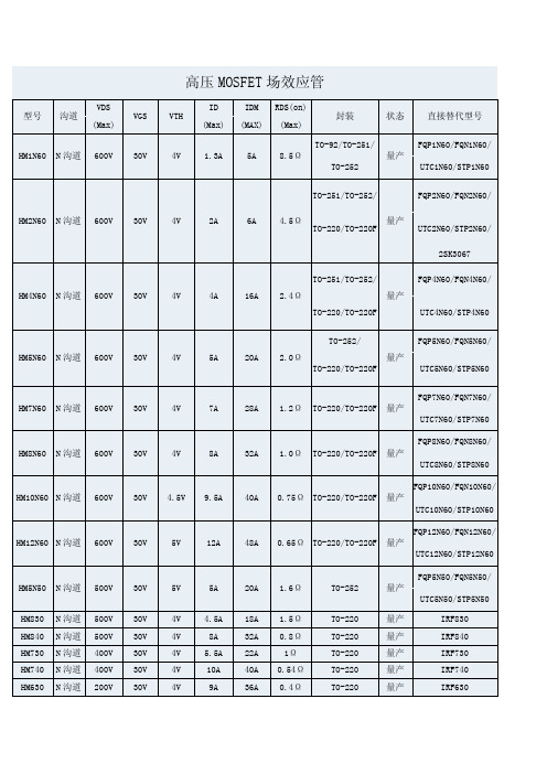
500V 500V 500V 400V 400V 200V
30V 30V 30V 30V 30V 30V
5V 4V 4V 4V 4V 4V
5A 4.5A 8A 5.5A 10A 9A
20A 18A 32A 22A 40A 36A
1.6Ω 1.5Ω 0.8Ω 1Ω 0.54Ω 0.4Ω
TO-252 TO-220 TO-220 TO-220 TO-220 TO-220
HM8N60
N 沟道
600V
30V
4V
8A
32A
1.0Ω
TO-220/TO-220F 量产 UTC8N60/STP8N60 FQP10N60/FQN10N60/HM10N60 NhomakorabeaN 沟道
600V
30V
4.5V
9.5A
40A
0.75Ω TO-220/TO-220F 量产 UTC10N60/STP10N60 FQP12N60/FQN12N60/
HM12N60 N 沟道
600V
30V
5V
12A
48A
0.65Ω TO-220/TO-220F 量产 UTC12N60/STP12N60 FQP5N50/FQN5N50/
HM5N50 HM830 HM840 HM730 HM740 HM630
N 沟道 N 沟道 N 沟道 N 沟道 N 沟道 N 沟道
TO-220/TO-220F
UTC2N60/STP2N60/ 2SK3067
TO-251/TO-252/ HM4N60 N 沟道 600V 30V 4V 4A 16A 2.4Ω TO-220/TO-220F TO-252/ HM5N60 N 沟道 600V 30V 4V 5A 20A 2.0Ω TO-220/TO-220F 量产 量产
FQA9N90C中文资料

BVDSS ∆BVDSS / ∆TJ
Drain-Source Breakdown Voltage
Breakdown Voltage Temperature Coefficient
VGS = 0 V, ID = 250 µA
900 --
ID = 250 µA, Referenced to 25°C -- 0.99
-55 to +150
300
Typ
Max
--
0.45
0.24
--
--
40
©2003 Fairchild Semiconductor Corporation
Units V A A A V mJ A mJ
V/ns W
W/°C °C °C
Units °C/W °C/W °C/W
Rev. A, March 2003
Output Capacitance
Crss
Reverse Transfer Capacitance
VDS = 25 V, VGS = 0 V, f = 1.0 MHz
-- 2100 2730 pF
-- 175 230
pF
-- 14
18
pF
Switching Characteristics
td(on)
FQA9N90C
元器件交易网
Electrical Characteristics
Symbol
Parameter
TC = 25°C unless otherwise noted
Test Conditions
Min Typ Max Units
Off Characteristics
--
good开关功率MOS扫盲篇
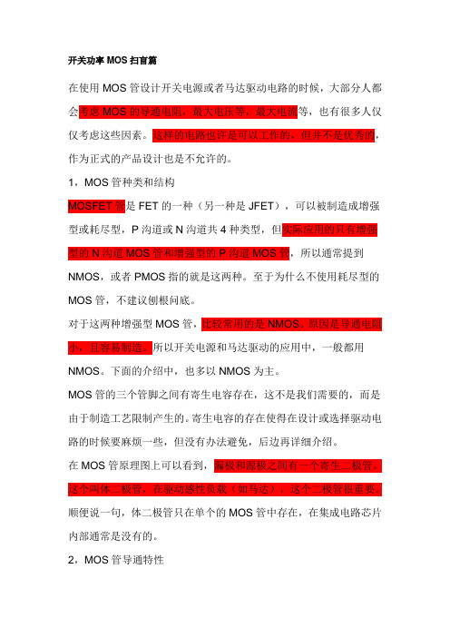
开关功率MOS扫盲篇在使用MOS管设计开关电源或者马达驱动电路的时候,大部分人都会考虑MOS的导通电阻,最大电压等,最大电流等,也有很多人仅仅考虑这些因素。
这样的电路也许是可以工作的,但并不是优秀的,作为正式的产品设计也是不允许的。
1,MOS管种类和结构MOSFET管是FET的一种(另一种是JFET),可以被制造成增强型或耗尽型,P沟道或N沟道共4种类型,但实际应用的只有增强型的N沟道MOS管和增强型的P沟道MOS管,所以通常提到NMOS,或者PMOS指的就是这两种。
至于为什么不使用耗尽型的MOS管,不建议刨根问底。
对于这两种增强型MOS管,比较常用的是NMOS。
原因是导通电阻小,且容易制造。
所以开关电源和马达驱动的应用中,一般都用NMOS。
下面的介绍中,也多以NMOS为主。
MOS管的三个管脚之间有寄生电容存在,这不是我们需要的,而是由于制造工艺限制产生的。
寄生电容的存在使得在设计或选择驱动电路的时候要麻烦一些,但没有办法避免,后边再详细介绍。
在MOS管原理图上可以看到,漏极和源极之间有一个寄生二极管。
这个叫体二极管,在驱动感性负载(如马达),这个二极管很重要。
顺便说一句,体二极管只在单个的MOS管中存在,在集成电路芯片内部通常是没有的。
2,MOS管导通特性导通的意思是作为开关,相当于开关闭合。
NMOS的特性,Vgs大于一定的值就会导通,适合用于源极接地时的情况(低端驱动),只要栅极电压达到4V或10V就可以了。
PMOS的特性,Vgs小于一定的值就会导通,适合用于源极接VCC 时的情况(高端驱动)。
但是,虽然PMOS可以很方便地用作高端驱动,但由于导通电阻大,价格贵,替换种类少等原因,在高端驱动中,通常还是使用NMOS。
3,MOS开关管损失不管是NMOS还是PMOS,导通后都有导通电阻存在,这样电流就会在这个电阻上消耗能量,这部分消耗的能量叫做导通损耗。
选择导通电阻小的MOS管会减小导通损耗。
现在的小功率MOS管导通电阻一般在几十毫欧左右,几毫欧的也有。
90n10场效应管参数
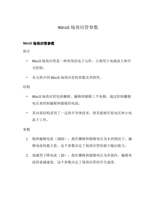
90n10场效应管参数90n10场效应管参数简介•90n10场效应管是一种常用的电子元件,主要用于电路放大和开关控制。
•本文将介绍90n10场效应管的参数及其特性。
结构•90n10场效应管包括栅极、漏极和源极三个电极,通过控制栅极电压来控制漏极和源极的电流。
•其内部结构采用了一定的半导体技术,使其能够在低电压和小电流下工作。
参数1.饱和漏极电流(IDSS):指在栅极和源极电压为0的情况下,漏极电流的最大值。
这个参数决定了场效应管的最大输出能力。
2.衰减型下降电流(ID):指在栅极和源极电压为负值时,漏极电流的衰减速度。
这个参数决定了场效应管的开关速度。
3.开启电压(VGS(ON)):指在给定的栅极电压下,源极和漏极之间开始导通所需的最小电压差。
这个参数决定了场效应管的开启特性。
4.关断电压(VGS(OFF)):指在给定的栅极电压下,源极和漏极之间不再导通所需的最大电压差。
这个参数决定了场效应管的关闭特性。
5.增益(Gain):指输出电流和输入电流之间的比例关系。
这个参数决定了场效应管的放大特性。
6.漏极电阻(RDS(ON)):指在饱和区时,源极和漏极之间的电阻大小。
这个参数决定了场效应管的导通能力。
特性•90n10场效应管具有以下特点:1.高输入阻抗:由于栅极和源极之间存在电容,使得场效应管具有很高的输入阻抗,可以很好地适应输入信号的变化。
2.低输入电流:由于栅极和源极之间的电容导致的漏极电流非常小,使得场效应管具有较低的输入电流,有利于减小功耗。
3.高频特性好:由于场效应管的内部结构较简单,不存在PN结,使得其在高频情况下响应速度较快,适用于高频放大电路。
4.体积小:场效应管体积小巧,可方便地进行集成电路的制作。
应用•90n10场效应管广泛应用于以下领域:1.放大电路:由于其具有较高的增益特性,可用于信号放大电路中,如音频放大器、功率放大器等。
2.开关电路:由于其具有较快的开关速度和较小的输入电流,可用于逻辑门、计时器、电源开关等控制电路中。
9N90
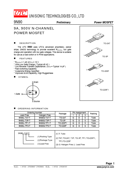
Packing
Tube Tube Tube Tube
电话:(0755)27858667 27858661 传真:(0755)27858707
Page 1
9N90
Preliminary
Power MOSFET
ABSOLUTE MAXIMUM RATING (TC =25°C, unless otherwise specified)
9N90L-T47-T
9N90G-T47-T
9N90L-T3P-T
9N90G-T3P-T
9N90L-TF1-T
9N90G-TF1-T
9N90L-TF3-T
9N90G-TF3-T
Package
TO-247 TO-3P TO-220F1 TO-220F
Pin Assignment 123 GDS GDS GDS GDS
PARAMETER
SYMBOL
RATINGS
UNIT
Drain-Source Voltage
VDSS
900
V
Gate-Source Voltage
VGSS
±30
V
Continuous Drain Current (TC = 25°C)
ID
9.0
A
Pulsed Drain Current (Note 2)
VSD IS
安VGS = 0 V, IS = 9.0 A
达ISM
1.4 V 9.0 A 36 A
Reverse Recovery Time Reverse Recovery Charge
众trr QRR
VGS = 0 V, IS = 9.0 A, dIF / dt =100 A/μs (Note 1)
FQA9N90
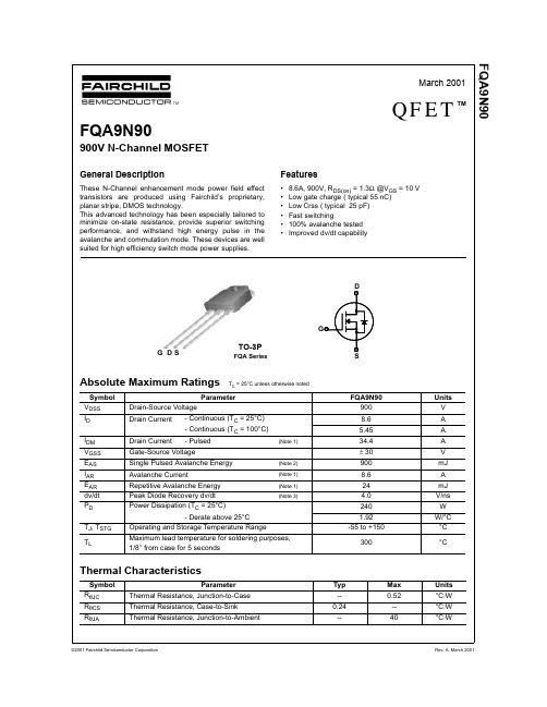
Operating and Storage Temperature Range
Maximum lead temperature for soldering purposes, 1/8" from case for 5 seconds
Thermal Characteristics
Symbol RθJC RθCS RθJA
FQA9N90
FQA9N90
Typical Characteristics (Continued)
BVDSS, (Normalized) Drain-Source Breakdown Voltage
1.2
1.1
1.0
0.9
※ Notes :
1. 2.
IVDG=S =2500Vμ
(Note 2)
Avalanche Current
(Note 1)
Repetitive Avalanche Energy
(Note 1)
Peak Diode Recovery dv/dt
(Note 3)
Power Dissipation (TC = 25°C) - Derate above 25°C
-55 to +150
300
Typ
Max
--
0.52
0.24
--
--
40
©2001 Fairchild Semiconductor Corporation
Units V A A A V mJ A mJ
V/ns W
W/°C °C °C
Units °C/W °C/W °C/W
Rev. A, March 2001
12
10
V = 180V DS
FQA9N90C
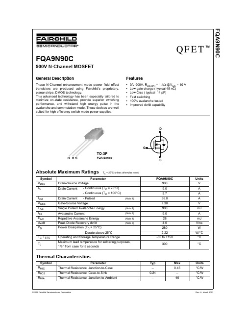
--
--
1.4
V
trr
Reverse Recovery Time
VGS = 0 V, IS = 9.0 A,
-- 550
--
ns
Qrr
Reverse Recovery Charge
dIF / dt = 100 A/µs
(Note 4) --源自6.5--µC
Notes:
1. Repetitive Rating : Pulse width limited by maximum junction temperature 2. L = 21mH, IAS = 9.0A, VDD = 50V, RG = 25 Ω, Starting TJ = 25°C 3. ISD ≤ 9.0A, di/dt ≤ 200A/µs, VDD ≤ BVDSS, Starting TJ = 25°C 4. Pulse Test : Pulse width ≤ 300µs, Duty cycle ≤ 2% 5. Essentially independent of operating temperature
(Note 2)
Avalanche Current
(Note 1)
Repetitive Avalanche Energy
(Note 1)
Peak Diode Recovery dv/dt
(Note 3)
Power Dissipation (TC = 25°C) - Derate above 25°C
100
101
VDS, Drain-Source Voltage [V]
Figure 5. Capacitance Characteristics
Capacitance [pF]
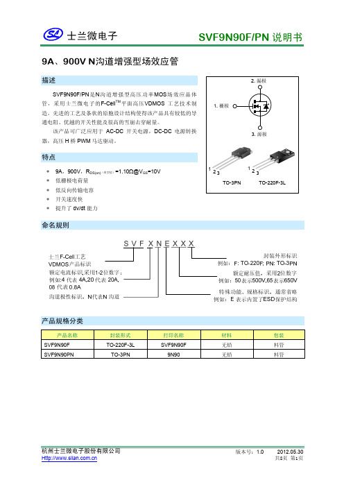
SVF9N90F(PN)说明书_1.0-L
漏源击穿电压(标准化)– BVDSS(V)
1.1 1.0
0.9
0.8 -100 -50
注:
1. VGS=0V 2. ID=250µA
0
50 100 150 200
结温 – TJ(°C)
漏极电流 - ID(A)
图9-1. 最大安全工作区域(SVF9N90F) 102
100µs 101
1ms
10ms
单位: mm
3.30±0.25
15.75±0.50 6.70±0.30
15.80±0.50
TO-3PN
9.80±0.50
1.47MAX 0.80±0.15 2.54 TYPE
2.80±0.30
0.50±0.15
单位:mm
杭州士兰微电子股份有限公司
版本号:1.0
该产品可广泛应用于 AC-DC 开关电源,DC-DC 电源转换 器,高压 H 桥 PWM 马达驱动。
1. 栅极
2. 漏极 3. 源极
特点
∗ 9A,900V,RDS(on)(典型值)=1.10Ω@VGS=10V ∗ 低栅极电荷量 ∗ 低反向传输电容 ∗ 开关速度快 ∗ 提升了 dv/dt 能力
1 23 TO-3PN
VGS=10V
VGS=20V
1.4
1.3
1.2
1.1
注:TJ=25°C
1.0
0
2
4
6
8
10
漏极电流 – ID(A)
漏源导通电阻 – RDS(ON)(Ω)
电容(pF)
3500 3000 2500 2000 1500 1000
500 0 0.1
图5. 电容特性
Ciss=Cgs+Cgd(Cds=shorted) Coss=Cds+Cgd Crss=Cgd
NCE65T900系列N-Channel超级接触点电源MOSFET说明书
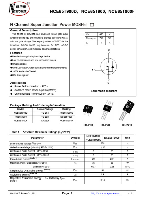
N-Channel Super Junction Power MOSFET ⅢGeneral DescriptionThe series of devices use advanced trench gate super junction technology and design to provide excellent R DS(ON) with low gate charge. This super junction MOSFET fits the industry’s AC-DC SMPS requirements for PFC, AC/DC power conversion, and industrial power applications. Features●New technology for high voltage device●Low on-resistance and low conduction losses●Small package●Ultra Low Gate Charge cause lower driving requirements ●100% Avalanche Tested●ROHS compliantApplication● Power factor correction(PFC)● Switched mode power supplies(SMPS)● Uninterruptible Power Supply(UPS)V DS650 V R DS(ON)TYP750 mΩ I D 5 APackage Marking And Ordering Information Device Device Package Marking NCE65T900D TO-263 NCE65T900D NCE65T900 TO-220 NCE65T900 NCE65T900F TO-220F NCE65T900FTable 1.Absolute Maximum Ratings (T C=25℃)Parameter SymbolNCE65T900NCE65T900DNCE65T900FUnitDrain-Source Voltage (V GS=0V)V DS650 V Gate-Source Voltage (V DS=0V) AC (f>1 Hz)V GS±30 V Continuous Drain Current at Tc=25°C I D (DC) 5 5* A Continuous Drain Current at Tc=100°C I D (DC) 3 3* A Pulsed drain current (Note 1)I DM (pluse)20 20* AMaximum Power Dissipation(Tc=25℃)Derate above 25°C P D460.37290.23WW/°CSingle pulse avalanche energy(Note2)E AS52 mJ Avalanche current(Note 1)I AR0.9 ARepetitive Avalanche energy ,t AR limited by T jmax (Note 1)E AR0.14 mJSchematic diagramTO-263 TO-220 TO-220FParameter SymbolNCE65T900NCE65T900DNCE65T900F UnitDrain Source voltage slope,V DS≤480 V, dv/dt50 V/ns Reverse diode dv/dt,V DS≤480 V,I SD<I D dv/dt 15 V/ns Operating Junction and Storage Temperature Range T J,T STG-55...+150 °C * limited by maximum junction temperatureTable 2. Thermal CharacteristicParameter SymbolNCE65T900NCE65T900DNCE65T900F UnitThermal Resistance,Junction-to-Case(Maximum)R thJC 2.72 4.3 °C /W Thermal Resistance,Junction-to-Ambient (Maximum)R thJA62 80 °C /W Table 3. Electrical Characteristics (TA=25℃unless otherwise noted)Parameter Symbol Condition Min Typ Max Unit On/off statesDrain-Source Breakdown Voltage BV DSS V GS=0V I D=250μA 650 V Zero Gate Voltage Drain Current(Tc=25℃) I DSS V DS=650V,V GS=0V 1 μA Zero Gate Voltage Drain Current(Tc=125℃) I DSS V DS=650V,V GS=0V 50 μA Gate-Body Leakage Current I GSS V GS=±20V,V DS=0V ±100 nA Gate Threshold Voltage V GS(th)V DS=V GS,I D=250μA 3 4 V Drain-Source On-State Resistance R DS(ON)V GS=10V, I D=2.5A 750 900 mΩ Dynamic CharacteristicsInput Capacitance C lssV DS=50V,V GS=0V,F=1.0MHz 370 pFOutput Capacitance C oss25 pF Reverse Transfer Capacitance C rss0.5 pFTotal Gate Charge Q gV DS=480V,I D=5A,V GS=10V 10.5 15 nCGate-Source Charge Q gs 2.6 nC Gate-Drain Charge Q gd 5.3 nC Switching timesTurn-on Delay Time t d(on)V DD=380V,I D=3A,R G=5Ω,V GS=10V 7 nSTurn-on Rise Time t r 3 nS Turn-Off Delay Time t d(off)52 62 nS Turn-Off Fall Time t f10 16 nS Source- Drain Diode CharacteristicsSource-drain current(Body Diode) I SDT C=25°C 5 APulsed Source-drain current(Body Diode) I SDM20 A Forward on voltage V SD Tj=25°C,I SD=5A,V GS=0V 0.9 1.2 VReverse Recovery Time t rrTj=25°C,I F=2.5A,di/dt=100A/μs 210 nSReverse Recovery Charge Q rr0.66 uC Peak reverse recovery current I rrm 6.5 A Notes: 1.Repetitive Rating: Pulse width limited by maximum junction temperature2. Tj=25℃,VDD=50V,VG=10V, R G=25ΩTYPICAL ELECTRICAL AND THERMAL CHARACTERISTICS (curves)Figure1. Safe operating area for TO-220,TO-263 Figure2. Safe operating area for TO-220FFigure3. Source-Drain Diode Forward Voltage Figure4. Output characteristicsFigure5. Transfer characteristics Figure6. Static drain-source on resistanceFigure7. R DS(ON) vs Junction Temperature Figure8. BV DSS vs Junction TemperatureFigure9. Maximum I D vs Junction Temperature Figure10. Gate charge waveformsFigure11. Capacitance Figure12. Transient Thermal ImpedanceFigure13. Transient Thermal Impedance for TO-220FTest circuit1)Gate charge test circuit & Waveform2)Switch Time Test Circuit:3)Unclamped Inductive Switching Test Circuit & WaveformsTO-263-3L Package InformationDimensions In Millimeters Dimensions In Inches SymbolMin. Max. Min. Max.A 4.32 4.57 0.170 0.180A1 - 0.25 0.010b 0.71 0.94 0.028 0.037b2 1.15 1.40 0.045 0.055c 0.46 0.61 0.018 0.024c2 1.22 1.40 0.048 0.055D 8.89 9.40 0.350 0.370D1 8.01 8.23 0.315 0.324E 10.04 10.28 0.395 0.405E1 7.88 8.08 0.310 0.318e 2.54 BSC 0.100 BSCL 14.73 15.75 0.580 0.620 L1 2.29 2.79 0.090 0.110 L2 1.15 1.39 0.045 0.055 L3 1.27 1.77 0.050 0.070TO-220-3L-C Package InformationSymbol Dimensions In Millimeters Dimensions In Inches Min. Max. Min. Max. A 4.400 4.600 0.173 0.181 A1 2.250 2.550 0.089 0.100 b 0.710 0.910 0.028 0.036 b1 1.170 1.370 0.046 0.054 c 0.330 0.650 0.013 0.026 c1 1.200 1.400 0.047 0.055 D 9.910 10.250 0.390 0.404 E 8.9500 9.750 0.352 0.384 E1 12.65012.9500.4980.510e 2.540 TYP.0.100 TYP.e1 4.980 5.180 0.196 0.204 F 2.650 2.950 0.104 0.116 H 7.900 8.100 0.311 0.319 h 0.000 0.300 0.000 0.012 L 12.900 13.400 0.508 0.528 L1 2.8503.2500.1120.128 V 7.500 REF.0.295 REF.Φ3.400 3.8000.1340.150TO-220F Package InformationSymbol Dimensions In Millimeters Dimensions In InchesMin.Max.Min.Max.A 4.500 4.900 0.177 0.193A1 2.340 2.740 0.092 0.108 A2 2.560 2.960 0.101 0.117 b1 0.700 0.900 0.028 0.035 b2 1.180 1.580 0.046 0.062c 0.400 0.600 0.016 0.024D 9.960 10.360 0.392 0.408E 15.670 15.970 0.617 0.629E1 6.500 6.900 0.256 0.272 E2 15.500 16.100 0.610 0.634e 2.540 TYP 0.100 TYPΦ 3.080 3.280 0.121 0.129 L 12.640 13.240 0.498 0.521 L1 3.030 3.430 0.119 0.135ATTENTION:■Any and all NCE products described or contained herein do not have specifications that can handle applications that require extremely high levels of reliability, such as life-support systems, aircraft's control systems, or other applications whose failure can be reasonably expected to result in serious physical and/or material damage. Consult with your NCE representative nearest you before using any NCE products described or contained herein in such applications.■NCE assumes no responsibility for equipment failures that result from using products at values that exceed, even momentarily, rated values (such as maximum ratings, operating condition ranges, or other parameters) listed in products specifications of any and all NCE products described or contained herein.■Specifications of any and all NCE products described or contained herein stipulate the performance, characteristics, and functions of the described products in the independent state, and are not guarantees of the performance, characteristics, and functions of the described products as mounted in the customer’s products or equipment. To verify symptoms and states that cannot be evaluated in an independent device, the customer should always evaluate and test devices mounted in the customer’s products or equipment.■NCE Power Semiconductor CO.,LTD. strives to supply high-quality high-reliability products. However, any and all semiconductor products fail with some probability. It is possible that these probabilistic failures could give rise to accidents or events that could endanger human lives, that could give rise to smoke or fire, or that could cause damage to other property. When designing equipment, adopt safety measures so that these kinds of accidents or events cannot occur. Such measures include but are not limited to protective circuits and error prevention circuits for safe design, redundant design, and structural design.■In the event that any or all NCE products(including technical data, services) described or contained herein are controlled under any of applicable local export control laws and regulations, such products must not be exported without obtaining the export license from the authorities concerned in accordance with the above law.■No part of this publication may be reproduced or transmitted in any form or by any means, electronic or mechanical, including photocopying and recording, or any information storage or retrieval system, or otherwise, without the prior written permission of NCE Power Semiconductor CO.,LTD.■Information (including circuit diagrams and circuit parameters) herein is for example only ; it is not guaranteed for volume production. NCE believes information herein is accurate and reliable, but no guarantees are made or implied regarding its use or any infringements of intellectual property rights or other rights of third parties.■Any and all information described or contained herein are subject to change without notice due to product/technology improvement, etc. When designing equipment, refer to the "Delivery Specification" for the NCE product that you intend to use.■This catalog provides information as of Mar. 2010. Specifications and information herein are subject to change without notice.。
9N90L-T3P-T中文资料
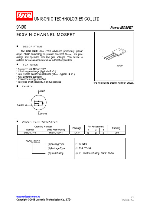
UNISONIC TECHNOLOGIES CO., LTD9N90 Power MOSFET900V N-CHANNEL MOSFETDESCRIPTIONThe UTC 9N90 uses UTC’s advanced proprietary, planar stripe, DMOS technology to provide excellent R DS(ON), low gate charge and operation with low gate voltages. This device is suitable for use as a load switch or in PWM applications.FEATURES* R DS(ON) = 1.4Ω @V GS = 10 V* Ultra low gate charge ( typical 45 nC )* Low reverse transfer capacitance ( C RSS = typical 14 pF ) * Fast switching capability * Avalanche energy specified* Improved dv/dt capability, high ruggednessSYMBOL1.Gate*Pb-free plating product number: 9N90LORDERING INFORMATIONOrdering Number Pin AssignmentNormal Lead Free Plating Package 1 2 3Packing9N90-T3P-T 9N90L-T3P-T TO-3P G D STubeABSOLUTE MAXIMUM RATING (T C =25℃, unless otherwise specified)PARAMETER SYMBOL RATINGS UNITDrain-Source Voltage V DSS 900 V Gate-Source Voltage V GSS ±30 VContinuous Drain Current(T C = 25℃) I D 9.0 A Pulsed Drain Current (Note 1) I DM 36 A Avalanche Current (Note 1) I AR 9.0 ASingle Pulsed(Note 2)E AS 900Avalanche Energy Repetitive(Note 1) E AR 28mJPeak Diode Recovery dv/dt (Note 3) dv/dt 4.0 V/ns 280 WPower Dissipation Derate above 25℃ P D2.22 W/℃ Junction Temperature T J 125 ℃ Operating Temperature T OPR -20 ~ +85 ℃ Storage Temperature T STG -40 ~ +150 ℃ Note: Absolute maximum ratings are those values beyond which the device could be permanently damaged. Absolute maximum ratings are stress ratings only and functional device operation is not implied.THERMAL CHARACTERISTICSPARAMETER SYMBOL MIN TYP MAX UNITJunction-to- Ambient θJA 40 ℃/W Junction-to-Case θJC 0.45 ℃/WELECTRICAL CHARACTERISTICS (T J =25℃, unless otherwise specified)PARAMETER SYMBOL TEST CONDITIONS MIN TYP MAX UNIT OFF CHARACTERISTICSDrain-Source Breakdown Voltage BV DSS V GS = 0 V, I D = 250 μA 900 V Drain-Source Leakage Current I DSS V DS = 900 V, V GS = 0 V 10 μAForward I GSSF V GS = 30 V, V DS = 0 V 100Gate-Body Leakage CurrentReverse I GSSRV GS = -30 V, V DS = 0 V -100nA Breakdown Voltage TemperatureCoefficientBV △DSS /△T J I D = 250 μA, Referenced to 25℃ 0.99 V/℃ON CHARACTERISTICS Gate Threshold Voltage V GS(TH) V DS = V GS , I D = 250 μA 3.0 5.0V Static Drain-Source On-Resistance R DS(ON) V GS = 10 V, I D = 4.5 A 1.12 1.4Ω DYNAMIC PARAMETERS Input Capacitance C ISS 2100 2730pFOutput Capacitance C OSS 175 230pFReverse Transfer Capacitance C RSSV DS = 25 V, V GS = 0 V,f = 1.0 MHz14 18 pF SWITCHING CHARACTERISTICS Turn-On Delay Time t D(ON) 50 110nsTurn-On Rise Time t R 120 250ns Turn-Off Delay Time t D(OFF) 100 210nsTurn-Off Fall Time t F V DD = 4500V, I D =11.0 A, R G = 25Ω (Note 4, 5) 75 160ns Total Gate Charge Q G 45 58 nCGate-Source Charge Q GS 13 nCGate-Drain Charge Q GDV DS = 720V, I D = 11.0A,V GS = 10 V (Note 4, 5)18 nCELECTRICAL CHARACTERISTICS(Cont.)PARAMETER SYMBOL TEST CONDITIONS MIN TYP MAX UNITDRAIN-SOURCE DIODE CHARACTERISTICS AND MAXIMUM RATINGS Drain-Source Diode Forward Voltage V SD V GS = 0 V, I S = 9.0 A 1.4VMaximum Continuous Drain-SourceDiode Forward CurrentI S 9.0 AMaximum Pulsed Drain-Source DiodeForward CurrentI SM 36 AReverse Recovery Time t RR 550 ns Reverse Recovery Charge Q RR V GS = 0 V, I S = 9.0 A,d IF / dt = 100 A/μs (Note 4) 6.5 μCNote 1. Repetitive Rating : Pulse width limited by maximum junction temperature2. L = 21mH, I AS = 9.0A, V DD = 50V, R G = 25 Ω, Starting T J = 25℃3. I SD ≤ 9.0A, di/dt ≤ 200A/μs, V DD ≤ BV DSS , Starting T J = 25℃4. Pulse Test : Pulse width ≤ 300μs, Duty cycle ≤ 2%5. Essentially independent of operating temperatureTEST CIRCUITFig. 2A Switching Test Circuit Fig. 2B Switching WaveformsFig. 3A Gate Charge Test Circuit Fig. 3B Gate Charge WaveformFig. 4A Unclamped Inductive Switching Test Circuit Fig. 4B Unclamped Inductive Switching WaveformsTEST CIRCUIT(Cont.)TYPICAL CHARACTERISTICSTYPICAL CHARACTERISTICS(Cont.)D r a i n -S o u r c e B r e a k d o w n V o l t a g e , B V D S S (N o r m a l i z e d )D r a i n -S o u r c e O n -R e s i s t a n c e , R D S (O N ) (N o r m a l i z e d )D r a i n C u r r e n t , I D (A )D r a i n C u r r e n t , I D (A )。
FQAF9N90中文资料
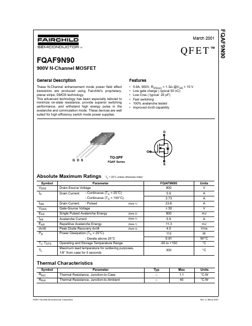
V
V/°C
µA µA nA nA
On Characteristics
VGS(th) RDS(on)
Gate Threshold Voltage
Static Drain-Source On-Resistance
gFS
Forward Transconductance
VDS = VGS, ID = 250 µA
IS
Maximum Continuous Drain-Source Diode Forward Current
--
--
5.9
A
ISM
Maximum Pulsed Drain-Source Diode Forward Current
--
-- 23.6
A
VSD
Drain-Source Diode Forward Voltage VGS = 0 V, IS = 5.9 A
Parameter Thermal Resistance, Junction-to-Case Thermal Resistance, Junction-to-Ambient
FQAF9N90 900 5.9 3.73 23.6 ± 30 900 5.9 11.3 4.0 113 0.91
-55 to +150
--
45 100
ns
-- 100 210
ns
-- 135 280
ns
(Note 4, 5)
--
80 170
ns
VDS = 720 V, ID = 8.6 A,
-- 55
72
nC
VGS = 10 V
-- 12
--
nC
90N10参数 ASEMI低压MOS管 场效应管
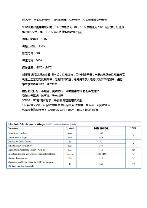
MOS管,也叫场效应管,90N10也属于场效应管,又叫绝缘栅场效应管
90N10的命名是有规则的,90代表电流为90A,10代表电压为10V,因此属于低压类型的MOS管,属于TO-220CB 直插型的封装产品。
最高正向电压:100V
高输出耐压:±50V
额定电流:90A
峰值电流:360A
操作温度:-55℃~150℃
ASEMI品牌的场效应管90N10,性能优势:工作时噪声低,产品的热稳定性能非常高,制造上工艺相对比较简单,定制时间较短,经常用于放大电路以及开关电路中,是日
常生活中最常用的一种二极管。
镭射激光打标,不褪色,黑胶材质:环氧塑脂材料包封稳定性好
引脚为无氧铜、抗弯曲、导电性好
90N10:5K/箱箱体材质:牛皮纸耐压耐磨抗冲击
1K/盒,50pcs/管,环保防静电牛皮环保纸盒防静电、易保存,可回收利用
90N10参数规格为:电流:90A 电压:100V;盒装:1000Pcs/盒。
一种900V大功率MOSFET器件结构设计

存在一定的偏差,并且随着击穿电压的增大,偏差
会越来越大,因此,对于低压的情况,K 取 0.9;当击
穿电压在 70 V耀200 V 时,K 取 0.8;当击穿高于 200 V
时,K 取 0.7,从而可令式(1)变为:
4
6 1013 3
Nb K
VB
(2)
执照设计要求,此处击穿电压要求大于 900 V, 远高于 200 V,因此 K 值取 0.7。将各数据代入式中, 得到外延区掺杂浓度为 1.68伊1014 cm-3。
漏端电极引出的,为了降低衬底与背面金属的接触
电阻,衬底必须采用高浓度掺杂;而外延层的掺杂浓
度依据击穿电压的要求,则要求要很低,一般情况外
延层的掺杂浓度会比衬底的浓度低 4 个数量级以
上。在这一情况下,当 VDMOS 器件在工艺加工过程
中经历高温的氧化、阱推等工步时,高掺杂的衬底就
会向低掺杂的外延层进行扩散,即有反扩发生,这将
来充当漂移区,承载漏结的高电压。同时为了降低
漂移区电阻,外延层下方应有一层电阻率极低的衬
底,在此选取 N 型<100>晶向的硅材料。已知外延层
掺杂浓度越小,电阻率越大,击穿电压越大。理想情
况下外延层掺杂浓度为:
4
6 1013 3
Nb
VB
(1)
但是,在实际 VDMOS 结构中,PN 结只有底部
挖掘其在武器装备体系中的关键性作用、更好地发挥其为电子及电机设备提供驱动的功能,设计并实
现一款 900 V 大功率 MOSFET 器件。以 VDMOS 器件为例分析其基本结构、工作原理和主要参数,通
过理论计算制定产品的外延层及栅氧等相关工艺参数,并对元胞尺寸进行了优化设计。终端结构采用
FQA9N90C
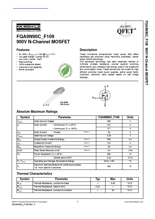
FQA9N90C_F109 900V N-Channel MOSFETJuly 2007QFET®FQA9N90C_F109900V N-Channel MOSFETFeatures•9A, 900V, R DS(on) = 1.4Ω @V GS = 10 V •Low gate charge ( typical 45 nC)•Low Crss ( typical 14pF)•Fastswitching•100% avalanche tested •Improved dv/dt capability •RoHS compliantDescriptionThese N-Channel enhancement mode power field effect transistors are produced using Fairchild’s proprietary, planar stripe, DMOS technology.This advanced technology has been especially tailored to minimize on-state resistance, provide superior switching performance, and withstand high energy pulse in the avalanche and commutation mode. These devices are well suited for high efficient switched mode power supplies, active power factor correction, electronic lamp ballast based on half bridge topology.Absolute Maximum RatingsThermal CharacteristicsDGSG SD TO-3PNFQA SeriesSymbolParameter FQA9N90C_F109UnitsV DSS Drain-Source Voltage 900V I D Drain Current - Continuous (T C = 25°C)9.0A - Continuous (T C = 100°C) 5.7A I DM Drain Current- Pulsed(Note 1)36A V GSS Gate-Source Voltage± 30V E AS Single Pulsed Avalanche Energy (Note 2)900mJ I AR Avalanche Current(Note 1)9.0A E AR Repetitive Avalanche Energy (Note 1)28mJ dv/dt Peak Diode Recovery dv/dt (Note 3)4.0V/ns P D Power Dissipation (T C = 25°C)280W - Derate above 25°C2.22W/°C T J , T STG Operating and Storage Temperature Range -55 to +150°C T LMaximum lead temperature for soldering purposes,1/8 from case for 5 seconds300°CSymbolParameterTypMaxUnitsR θJC Thermal Resistance, Junction-to-Case --0.45°C /W R θCS Thermal Resistance, Case-to-Sink 0.24--°C /W R θJAThermal Resistance, Junction-to-Ambient--40°C /W查询FQA9N90C_07供应商NOTES:1. Repetitive Rating : Pulse width limited by maximum junction temperature2. L = 21mH, I AS =9.0A, V DD = 50V, R G = 25 Ω, Starting T J = 25°C3. I SD ≤ 9.0A, di/dt ≤200A/µs, V DD ≤ BV DSS, Starting T J = 25°C4. Pulse Test : Pulse width ≤ 300µs, Duty cycle ≤ 2%5. Essentially independent of operating temperatureDS(on)GS D g FS Forward Transconductance V DS = 50 V, I D = 4.5 A (Note 4)--9.2--S Dynamic CharacteristicsC iss Input Capacitance V DS = 25 V, V GS = 0 V, f = 1.0 MHz--21002730pF C oss Output Capacitance--175230pF C rss Reverse Transfer Capacitance --1418pF Switching Characteristicst d(on)Turn-On Delay Time V DD = 450 V, I D = 11.0A,R G = 25 Ω(Note 4, 5)--50110ns t r Turn-On Rise Time --120250ns t d(off)Turn-Off Delay Time --100210ns t f Turn-Off Fall Time --75160ns Q g Total Gate Charge V DS = 720 V, I D = 11.0A,V GS = 10 V(Note 4, 5)--4558nC Q gs Gate-Source Charge --13--nC Q gd Gate-Drain Charge--18--nCDrain-Source Diode Characteristics and Maximum RatingsI S Maximum Continuous Drain-Source Diode Forward Current ----9.0A I SM Maximum Pulsed Drain-Source Diode Forward Current ----36A V SD Drain-Source Diode Forward Voltage V GS = 0 V, I S =9.0 A---- 1.4V t rr Reverse Recovery Time V GS = 0 V, I S = 9.0 A,dI F / dt = 100 A/µs (Note 4)--550--ns Q rrReverse Recovery Charge-- 6.5--µCResistive Switching Test Circuit & WaveformsUnclamped Inductive Switching Test Circuit & WaveformsDimensions in Millimeters。
大功率 mosfet

大功率 mosfet
大功率 MOSFET(金属氧化物半导体场效应晶体管)是一种用于高功率应用的场效应晶体管。
它具有较低的导通电阻和较高的开关速度,适用于需要处理大电流和高电压的电路。
以下是一些常见的大功率 MOSFET:
1. Infineon Technologies IRFP4006PBF:这是一款N沟道增强型功率 MOSFET,额定电流为195安培,额定电压为600伏特。
2. STMicroelectronics STW75N60DM2:这是一款N沟道增强型功率 MOSFET,额定电流为75安培,额定电压为600伏特。
3. Fairchild Semiconductor FQA9N90C:这是一款N沟道增强型功率 MOSFET,额定电流为9安培,额定电压为900伏特。
4. International Rectifier IRFB7430PBF:这是一款N 沟道增强型功率 MOSFET,额定电流为195安培,额定电压为300伏特。
这些大功率 MOSFET 在不同的应用中具有不同的特性和参数。
选择适合特定应用的大功率 MOSFET 需要考虑电流和电压需求、开关速度、导通电阻、温度特性等因素。
在选
择时,建议参考厂商提供的数据手册和应用指南,以确保选取合适的器件。
90n20d场效应管参数
90n20d场效应管参数
"90n20d"指的是场效应管(Field-Effect Transistor,简称FET)的型号或规格。
通常,FET的型号由一系列数字和字母组成,表示其特定的性能和参数。
在这种情况下, "90n20d" 可能是特定制造商或系列的型号。
一般来说,FET的参数包括但不限于:
1. 漏极-源极饱和电流(Idss):在漏极-源极之间施加最大漏极-源极电压时的漏极电流。
2. 漏极-源极截止电流(Idoff):在零漏极-源极电压下的漏极电流。
3. 漏极-源极电流(Id):在实际工作条件下的漏极电流。
4. 漏极-源极电压(Vds):漏极和源极之间的电压。
5. 栅极-源极电压(Vgs):栅极和源极之间的电压。
6. 栅极漏极电流(Igs):从栅极流向漏极的电流。
7. 漏极电阻(Rds(on)):在导通状态下,漏极和源极之间的电阻。
8. 功率(P): FET的最大功率处理能力。
请注意,这些参数可能会在不同的型号和制造商之间有所变化。
如果您能提供更具体的型号或制造商信息,我可能能够提供更详细的参数。
如果有可能,请查阅相关的型号手册或数据表,以获取准确的参数信息。
FAIRCHILD FQA9N90C_F109 900V N-Channel MOSFET 说明书
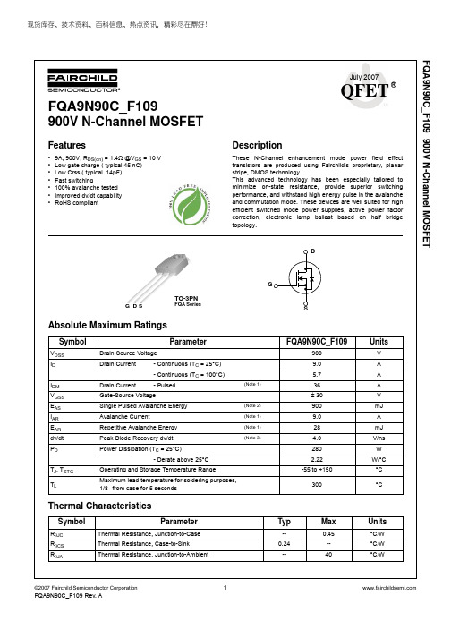
现货库存、技术资料、百科信息、热点资讯,精彩尽在鼎好!FQA9N90C_F109 900V N-Channel MOSFETJuly 2007QFET®FQA9N90C_F109900V N-Channel MOSFETFeatures•9A, 900V, R DS(on) = 1.4Ω @V GS = 10 V •Low gate charge ( typical 45 nC)•Low Crss ( typical 14pF)•Fast switching•100% avalanche tested •Improved dv/dt capability •RoHS compliantDescriptionThese N-Channel enhancement mode power field effect transistors are produced using Fairchild’s proprietary, planar stripe, DMOS technology.This advanced technology has been especially tailored to minimize on-state resistance, provide superior switching performance, and withstand high energy pulse in the avalanche and commutation mode. These devices are well suited for high efficient switched mode power supplies, active power factor correction, electronic lamp ballast based on half bridge topology.Absolute Maximum RatingsThermal CharacteristicsDGSG SD TO-3PNFQA SeriesSymbolParameter FQA9N90C_F109UnitsV DSS Drain-Source Voltage 900V I D Drain Current - Continuous (T C = 25°C)9.0A - Continuous (T C = 100°C) 5.7A I DM Drain Current- Pulsed(Note 1)36A V GSS Gate-Source Voltage± 30V E AS Single Pulsed Avalanche Energy (Note 2)900mJ I AR Avalanche Current(Note 1)9.0A E AR Repetitive Avalanche Energy (Note 1)28mJ dv/dt Peak Diode Recovery dv/dt (Note 3)4.0V/ns P D Power Dissipation (T C = 25°C)280W - Derate above 25°C2.22W/°C T J , T STG Operating and Storage Temperature Range -55 to +150°C T LMaximum lead temperature for soldering purposes,1/8 from case for 5 seconds300°CSymbolParameterTypMaxUnitsR θJC Thermal Resistance, Junction-to-Case --0.45°C /W R θCS Thermal Resistance, Case-to-Sink 0.24--°C /W R θJAThermal Resistance, Junction-to-Ambient--40°C /WNOTES:1. Repetitive Rating : Pulse width limited by maximum junction temperature2. L = 21mH, I AS =9.0A, V DD = 50V, R G = 25 Ω, Starting T J = 25°C3. I SD ≤ 9.0A, di/dt ≤200A/µs, V DD ≤ BV DSS, Starting T J = 25°C4. Pulse Test : Pulse width ≤ 300µs, Duty cycle ≤ 2%5. Essentially independent of operating temperatureDS(on)GS D g FS Forward Transconductance V DS = 50 V, I D = 4.5 A (Note 4)--9.2--S Dynamic CharacteristicsC iss Input Capacitance V DS = 25 V, V GS = 0 V, f = 1.0 MHz--21002730pF C oss Output Capacitance--175230pF C rss Reverse Transfer Capacitance --1418pF Switching Characteristicst d(on)Turn-On Delay Time V DD = 450 V, I D = 11.0A,R G = 25 Ω(Note 4, 5)--50110ns t r Turn-On Rise Time --120250ns t d(off)Turn-Off Delay Time --100210ns t f Turn-Off Fall Time --75160ns Q g Total Gate Charge V DS = 720 V, I D = 11.0A,V GS = 10 V(Note 4, 5)--4558nC Q gs Gate-Source Charge --13--nC Q gd Gate-Drain Charge--18--nCDrain-Source Diode Characteristics and Maximum RatingsI S Maximum Continuous Drain-Source Diode Forward Current ----9.0A I SM Maximum Pulsed Drain-Source Diode Forward Current ----36A V SD Drain-Source Diode Forward Voltage V GS = 0 V, I S =9.0 A---- 1.4V t rr Reverse Recovery Time V GS = 0 V, I S = 9.0 A,dI F / dt = 100 A/µs (Note 4)--550--ns Q rrReverse Recovery Charge-- 6.5--µCResistive Switching Test Circuit & WaveformsUnclamped Inductive Switching Test Circuit & WaveformsDimensions in MillimetersPDP-SPM™。
fqpf9n90场效应管参数
场效应管参数一、场效应管概述场效应管(Field Effect Transistor,简称FET)是一种使用电场控制电流的半导体器件,是现代电子技术中应用广泛的一种元件。
与双极型晶体管相比,场效应管具有输入电阻高、输入电容小、噪声系数低、体积小、功耗低等优点,因此在各种电子设备中得到了广泛的应用。
二、场效应管参数1. 饱和漏-源电流(IDSS)饱和漏-源电流IDSS是指在栅极和源极之间的电压为零时,漏极和源极之间的最大电流。
IDSS是场效应管的最大漏-源电流,也是场效应管的一个重要参数。
2. 静态工作点(Q点)静态工作点就是场效应管在直流状态下的工作点,通常用静态栅-源电压Ugsq和静态漏-源电流Idsq来描述。
静态工作点的选择直接影响着场效应管的放大特性和工作稳定性。
3. 灵敏度场效应管的灵敏度是指当栅-源电压变化时,漏-源电流的变化量与栅-源电压的变化量之比。
灵敏度越大,表示场效应管对栅-源电压的变化更为敏感。
4. 饱和电流饱和电流是指当场效应管的栅-源电压足够大时,漏-源电流达到最大值。
饱和电流的大小决定了场效应管的输出功率。
5. 输入电容(Ciss)输入电容是指场效应管的栅-源电容和栅-漏电容之和。
输入电容的大小直接影响了场效应管的输入电阻。
6. 输、输出电阻输、输出电阻分别是指场效应管的输入电阻和输出电阻。
输、输出电阻的大小直接影响了场效应管的放大特性和匹配特性。
7. 开启电压(VGS(th))开启电压是指当场效应管的栅-源电压大于一定值时,场效应管开始导通。
开启电压的大小直接影响了场效应管的饱和电流和输出功率。
8. 最大耗散功率(Pd)最大耗散功率是指场效应管在允许工作条件下所能承受的最大功率。
超过最大耗散功率会导致场效应管损坏。
三、场效应管参数的选取原则1. 静态工作点的选择原则静态工作点的选择应根据具体应用来确定,一般应使得静态漏-源电流较大,但不能太大。
2. 灵敏度的选择原则灵敏度的大小直接影响了场效应管在信号放大时的放大倍数,应根据具体应用需求来确定。
WGA9N90-E-A0
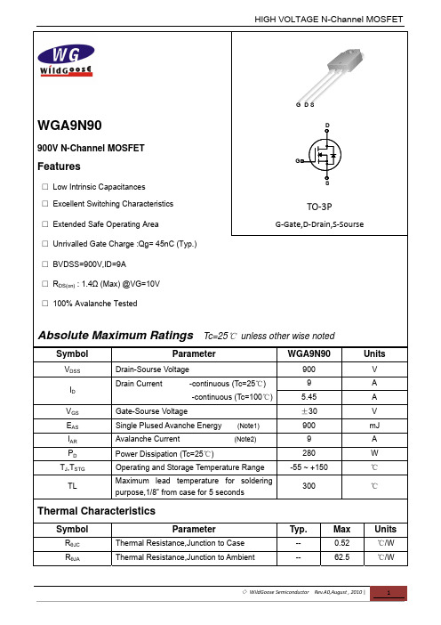
Figure 5. Capacitance Characteristics
Figure 6. Gate Charge Characteristics
◇ WildGoose Semiconductor Rev.A0,August , 2010 |
3
HIGH VOLTAGE N-Channel MOSFET
TJ, Junction Temperature [ C]
Figure 7. Breakdown Voltage Variation
Figure 8. On-Resistance Variation
10 10
2
Operation in This Area is Limited by R DS(on)
900 ---
-1.0 --
--10 100
V
V/℃ μA μA
---
---
100 -100
nA nA
On Characteristics
VGS(th) RDS(on) Date Threshold Voltage Static Drain-Sourse On-Resistance Id=250uA,Vds=Vgs Id=4.5A,Vgs=10V 3 ---5 1.4 V Ω
10
1
150 C
o
ID, Drain Current [A]
ID, Drain Current [A]
25 C
0
o
-55 C
o
10
0
10
10
-1
※ Notes : 1. 250μ s Pulse Test 2. TC = 25℃
※ Notes : 1. VDS = 50V 2. 250μ s Pulse Test
9n50场效应管参数

9n50场效应管参数9N50场效应管参数1. 引言场效应管(Field Effect Transistor,FET)是一种常用的电子器件,它是由半导体材料制成的三端口器件,其中最重要的参数之一是它的特性参数。
本文将重点介绍9N50场效应管的参数。
2. 9N50场效应管的基本介绍 9N50是一种N沟道MOS 场效应管,它具有高耐压和低导通电阻的特点。
它的工作原理是通过控制栅极电压来调节源极与漏极之间的电流。
3. 参数说明 3.1 额定值 - 额定电压(Vds):9N50场效应管的额定工作电压范围是50V。
- 额定电流(Id):9N50场效应管的额定工作电流范围是9A。
- 额定功率(Pd):9N50场效应管的额定功率范围是125W。
- 阻抗:9N50场效应管的输入和输出端之间的阻抗一般较低,可以提供较好的信号传输性能。
3.2 电流指标 - 静态电流放大系数(K):静态电流放大系数是衡量场效应管放大能力的重要参数。
9N50场效应管的静态电流放大系数通常在60~120之间。
- 饱和漏电流(Idss):饱和漏电流是指在栅极电压为零时,源极与漏极之间的漏电流。
一般情况下,9N50场效应管的饱和漏电流为3~10mA。
3.3 动态特性 - 开启电压(Vgs(th)):指的是栅极电压达到一定程度时,场效应管开始导通的电压。
9N50场效应管的开启电压范围一般为2~4V。
- 输入电容(Ciss):指的是场效应管输入端的电容,通常表示为场效应管输入与输出之间的总电容。
9N50场效应管的输入电容通常为2000pF。
- 输出电容(Coss):指的是场效应管输出端的电容,通常表示为源极与漏极之间的电容。
9N50场效应管的输出电容通常为500pF。
- 反向传输电容(Crss):指的是控制栅极之外的两个极间的电容。
9N50场效应管的反向传输电容通常为50pF。
4. 应用领域 9N50场效应管在各种电子设备中广泛应用,特别在功率放大电路和开关电路中最为常见。
- 1、下载文档前请自行甄别文档内容的完整性,平台不提供额外的编辑、内容补充、找答案等附加服务。
- 2、"仅部分预览"的文档,不可在线预览部分如存在完整性等问题,可反馈申请退款(可完整预览的文档不适用该条件!)。
- 3、如文档侵犯您的权益,请联系客服反馈,我们会尽快为您处理(人工客服工作时间:9:00-18:30)。
UNISONIC TECHNOLOGIES CO., LTD9N90Power MOSFET900V N-CHANNEL MOSFETDESCRIPTIONThe UTC 9N90 uses UTC’s advanced proprietary, planar stripe, DMOS technology to provide excellent R DS(ON), low gate charge and operation with low gate voltages. This device is suitable for use as a load switch or in PWM applications.FEATURES* R DS(ON) = 1.4Ω @V GS = 10 V* Ultra low gate charge ( typical 45 nC )* Low reverse transfer capacitance ( C RSS = typical 14 pF ) * Fast switching capability * Avalanche energy specified* Improved dv/dt capability, high ruggednessSYMBOL1.GateLead-free: 9N90L Halogen-free: 9N90GORDERING INFORMATIONOrdering Number Pin AssignmentNormal Lead Free Halogen Free Package 1 2 3 Packing9N90-T3P-T 9N90L-T3P-T 9N90G-T3P-T TO-3P G D S Tube (3) G: Halogen Free, L: Lead Free,ABSOLUTE MAXIMUM RATING (T C =25℃, unless otherwise specified)PARAMETER SYMBOL RATINGS UNITDrain-Source Voltage V DSS 900 V Gate-Source Voltage V GSS ±30 VContinuous Drain Current(T C = 25℃) I D 9.0 A Pulsed Drain Current (Note 1) I DM 36 A Avalanche Current (Note 1) I AR 9.0 ASingle Pulsed(Note 2)E AS 900Avalanche Energy Repetitive(Note 1) E AR 28mJPeak Diode Recovery dv/dt (Note 3) dv/dt 4.0 V/ns 280 WPower Dissipation Derate above 25℃ P D2.22 W/℃ Junction Temperature T J 150 ℃ Storage Temperature T STG -55 ~ +150 ℃ Note: Absolute maximum ratings are those values beyond which the device could be permanently damaged. Absolute maximum ratings are stress ratings only and functional device operation is not implied.THERMAL CHARACTERISTICSPARAMETER SYMBOL MIN TYP MAX UNITJunction-to- Ambient θJA 40 ℃/W Junction-to-Case θJC 0.45 ℃/WELECTRICAL CHARACTERISTICS (T J =25℃, unless otherwise specified)PARAMETER SYMBOL TEST CONDITIONS MIN TYP MAX UNIT OFF CHARACTERISTICSDrain-Source Breakdown Voltage BV DSS V GS = 0 V, I D = 250 μA 900 V Drain-Source Leakage Current I DSS V DS = 900 V, V GS = 0 V 10 μAForward I GSSF V GS = 30 V, V DS = 0 V 100Gate-Body Leakage Current Reverse I GSSR V GS = -30 V, V DS = 0 V -100nABreakdown Voltage TemperatureCoefficientBV △DSS /△T J I D = 250 μA, Referenced to 25℃ 0.99 V/℃ON CHARACTERISTICS Gate Threshold Voltage V GS(TH) V DS = V GS , I D = 250 μA 2.0 4.0V Static Drain-Source On-Resistance R DS(ON) V GS = 10 V, I D = 4.5 A 1.12 1.4Ω DYNAMIC PARAMETERS Input Capacitance C ISS 2100 2730pFOutput Capacitance C OSS 175 230pFReverse Transfer Capacitance C RSSV DS = 25 V, V GS = 0 V,f = 1.0 MHz14 18 pF SWITCHING CHARACTERISTICS Turn-On Delay Time t D(ON) 50 110ns Turn-On Rise Time t R 120 250ns Turn-Off Delay Time t D(OFF) 100 210nsTurn-Off Fall Time t F V DD = 4500V, I D =11.0 A,R G = 25Ω (Note 4, 5) 75 160ns Total Gate Charge Q G 45 58 nCGate-Source Charge Q GS 13 nCGate-Drain Charge Q GDV DS = 720V, I D = 11.0A,V GS = 10 V (Note 4, 5)18 nCELECTRICAL CHARACTERISTICS(Cont.)PARAMETER SYMBOL TEST CONDITIONS MIN TYP MAX UNITDRAIN-SOURCE DIODE CHARACTERISTICS AND MAXIMUM RATINGS Drain-Source Diode Forward Voltage V SD V GS = 0 V, I S = 9.0 A 1.4VMaximum Continuous Drain-SourceDiode Forward CurrentI S 9.0 AMaximum Pulsed Drain-Source DiodeForward CurrentI SM 36 AReverse Recovery Time t RR 550 ns Reverse Recovery Charge Q RR V GS = 0 V, I S = 9.0 A,d IF / dt = 100 A/μs (Note 4) 6.5 μCNote 1. Repetitive Rating : Pulse width limited by maximum junction temperature2. L = 21mH, I AS = 9.0A, V DD = 50V, R G = 25 Ω, Starting T J = 25℃3. I SD ≤ 9.0A, di/dt ≤ 200A/μs, V DD ≤ BV DSS , Starting T J = 25℃4. Pulse Test : Pulse width ≤ 300μs, Duty cycle ≤ 2%5. Essentially independent of operating temperatureTEST CIRCUITFig. 2A Switching Test Circuit Fig. 2B Switching WaveformsFig. 3A Gate Charge Test Circuit Fig. 3B Gate Charge WaveformFig. 4A Unclamped Inductive Switching Test Circuit Fig. 4B Unclamped Inductive Switching WaveformsTEST CIRCUIT(Cont.)TYPICAL CHARACTERISTICSUTC assumes no responsibility for equipment failures that result from using products at values thatexceed, even momentarily, rated values (such as maximum ratings, operating condition ranges, or other parameters) listed in products specifications of any and all UTC products described or contained herein. UTC products are not designed for use in life support appliances, devices or systems wheremalfunction of these products can be reasonably expected to result in personal injury. Reproduction inwhole or in part is prohibited without the prior written consent of the copyright owner. The informationpresented in this document does not form part of any quotation or contract, is believed to be accurateand reliable and may be changed without notice.。
