Bicoloring Steiner Triple Systems
IEEE拒绝收录的138个会议列表-推荐下载

IEEE拒绝收录的138个会议列表2011-10-27 14:54:18| 分类:EI、ISTP检索国际 | 标签:ieee 收录 138 会议列表 |字号大中小订阅IEEE拒绝收录的138个会议列表138个会议名单如下:2010 2nd Asia-Pacific Conference on Information Processing (APCIP)2010 2nd International Asia Symposium on Intelligent Interaction and Affective Computing & 2010 2nd International onInnovation Management (ASIA-ICIM)2010 2nd International Conference on Future Computer and Communication (FCC) 2010 2nd International Conference on Information and Multimedia Technology (ICIMT)2010 2nd International Conference on Intellectual Technique in Industrial Practice (ITIP 2010)2010 2nd International Conference on Multimedia and Computational Intelligence (ICMCI)2010 2nd International Conference on Research Challenges in Computer Science (ICRCCS)2010 2nd International Symposium on Computer Network and Multimedia Technology (CNMT 2010)2010 3rd International Conference on Computational Intelligence and Industrial Application (PACIIA)2010 3rd International Conference on Environmental and Computer Science (ICECS) 2010 3rd International Conference on Machine Vision (ICMV)2010 3rd International Conference on Power Electronics and Intelligent Transportation System (PEITS)2010 4th International Conference on Intelligent Information Technology Application (IITA)2010 6th International Conference on MEMS, NANO, and Smart Systems (ICMENS) 2010 First International Conference on Cellular, Molecular Biology, Biophysics and Bioengineering (CMBB)2010 IIS 2nd International Conference on Signal Processing, Robotics and Automation (ICSRA 2010)2010 International Asia Conference on Optical Instrument and Measurement (ACPIM)2010 International Conference on Bio-Inspired Systems and Signal Processing (ICBSSP)2010 International Conference on Biology, Environment and Chemistry (ICBEC) 2010 International Conference on Broadcast Technology and MultimediaCommunication (BTMC)2010 International Conference on Circuit and Signal Processing (ICCSP)2010 International Conference on Communication and Vehicular Technology (ICCVT)2010 International Conference on Computational Intelligence and Vehicular System (CIVS)2010 International Conference on Computer and Computational Intelligence (ICCCI) 2010 International Conference on Computer and Software Modeling (ICCSM)2010 International Conference on Computer Science and Sports Engineering (CSSE) 2010 International Conference on Computer-Aided Manufacturing and Design (CMD)2010 International Conference on Construction and Project Management (ICCPM) 2010 International Conference on Digital Enterprise and Digital Manufacturing (DEDM)2010 International Conference on E-business, Management and Economics (ICEME) 2010 International Conference on Economics, Business and Management (ICEBM) 2010 International Conference on Electrical Engineering and Automatic Control (ICEEAC)2010 International Conference on Embedded Systems and Microprocessors (ICESM) 2010 International Conference on Engineering Education and Educational Technology (EEET)2010 International Conference on Future Biomedical Information Engineering (FBIE) 2010 International Conference on Future Computer, Control and Communication (FCCC)2010 International Conference on Future Industrial Engineering and Application (ICFIEA)2010 International Conference on Future Information Technology (ICFIT)2010 International Conference on Future Information Technology and Computing (FITC)2010 International Conference on Graphic and Image Processing (ICGIP)2010 International Conference on Information and Finance (ICIF)2010 International Conference on Information Security and Artificial Intelligence (ISAI)2010 International Conference on Intelligence and Information Technology (ICIIT) 2010 International Conference on Intelligent Network and Computing (ICINC)2010 International Conference on Management Science (ICMS)2010 International Conference on Management Science and Information Engineering (ICMSIE)2010 International Conference on Manufacturing Science and Technology (ICMST) 2010 International Conference on Measurement and Control Engineering (ICMCE) 2010 International Conference on Mechanical and Aerospace Engineering (ICMAE) 2010 International Conference on Mechanical Engineering, Robotics and Aerospace (ICMERA)2010 International Conference on Modeling, Simulation and Control (ICMSC 2010)2010 International Conference on Nano Science and Technology (ICNST)2010 International Conference on Nanotechnology and Biosensors (ICNB)2010 International Conference on Nuclear Energy and Engineering Technology (NEET)2010 International Conference on Physics Science and Technology (ICPST)2010 International Conference on Psychology, Psychological Sciences and Computer Science (PPSCS)2010 International Conference on Remote Sensing (ICRS)2010 International Conference on Semiconductor Laser and Photonics (ICSLP)2010 International Conference on Services Science, Management and Engineering (SSME)2010 International Conference on Signal and Information Processing (ICSIP)2010 International Conference on Software and Computing Technology (ICSCT) 2010 International Conference on Sport Medicine, Sport Science, and Computer Science (SMSSCS)2010 ISECS International Colloquium on Computing, Communication, Control, and Management (CCCM 2010)2010 Second International Conference on E-Learning, E-Business, Enterprise Information Systems, and E-Government(EEEE)2010 Second International Conference on Test and Measurement (ICMT)2010 Second International Seminar on Business and Information Management (ISBIM)2010 Third International Conference on Computer and Electrical Engineering (ICCEE)2010 Third International Conference on Education Technology and Training (ETT) 2010 Third International Symposium on Intelligent Ubiquitous Computing and Education (IUCE)2010 Third Pacific-Asia Conference on Web Mining and Web-Based Application (WMWA)2011 15th Global Chinese Conference on Computers in Education (GCCCE)2011 2nd Asia-Pacific Conference on Wearable Computing Systems (APWCS)2011 2nd International Conference on Biomedical Engineering and Computer Science (ICBECS)2011 2nd International Conference on Biotechnology and Food Science (ICBFS) 2011 2nd International Conference on Data Storage and Data Engineering (DSDE) 2011 2nd International Conference on Environmental Science and Technology (ICEST)2011 2nd International Conference on Financial Theory and Engineering (ICFTE) 2011 2nd International Conference on Mechanical, Industrial, and Manufacturing Technologies (MIMT)2011 2nd Intl Conf on Innovative Computing & Communication and 2010 Asia-Pacific Conf on Information Technology &Ocean Engineering, (CICC-ITOE)2011 2nd World Congress on Computer Science and Information Engineering (CSIE) 2011 3rd IEEE International Conference on Information Management and Engineering (ICIME)2011 3rd International Conference on Bioinformatics and Biomedical Technology (ICBBT 2011)2011 3rd International Conference on Computer and Automation Engineering (ICCAE)2011 3rd International Conference on Computer and Network Technology (ICCNT) 2011 3rd International Conference on Computer Design and Applications (ICCDA 2011)2011 3rd International Conference on Computer Modeling and Simulation (ICCMS) 2011 3rd International Conference on E-business and Information System Security (EBISS)2011 3rd International Conference on Machine Learning and Computing (ICMLC) 2011 3rd International Conference on Networks Security, Wireless Communications and Trusted Computing (NSWCTC)2011 3rd International Conference on Signal Acquisition and Processing (ICSAP) 2011 3rd International Workshop on Education Technology and Computer Science (ETCS)2011 4th IEEE International Conference on Computer Science and Information Technology (ICCSIT 2011)2011 IEEE International Conference on Information and Education Technology (ICIET)2011 IEEE International Conference on Smart Grid and Clean Energy Technologies (ICSGCE)2011 International Conference on Applied Physics and Mathematics (ICAPM 2011) 2011 International Conference on Bioinformatics and Computational Biology (ICBCB)2011 International Conference on Bioscience, Biochemistry and Bioinformatics (ICBBB)2011 International Conference on Communication and Electronics Information (ICCEI)2011 International Conference on Computer and Communication Devices (ICCCD) 2011 International Conference on Computer Applications and Network Security (ICCANS)2011 International Conference on Computers, Communications, Control and Automation (CCCA)2011 International Conference on Control, Robotics and Cybernetics (ICCRC)2011 International Conference on Data Engineering and Internet Technology (DEIT) 2011 International Conference on Database and Data Mining (ICDDM)2011 International Conference on Digital Convergence (ICDC)2011 International Conference on Economics and Finance Research (ICEFR)2011 International Conference on Economics, Business and Marketing Management (CEBMM)2011 International Conference on Economics, Trade and Development (ICETD) 2011 International Conference on Electrical Energy and Networks (ICEEN)2011 International Conference on Energy and Environment (ICEE)2011 International Conference on Engineering and Information Management (ICEIM) 2011 International Conference on Environment Science and Engineering (ICESE) 2011 International Conference on Environmental Science and Development (ICESD) 2011 International Conference on Future Environment and Energy (ICFEE 2011) 2011 International Conference on Fuzzy Systems and Neural Computing (FSNC) 2011 International Conference on Information and Computer Applications (ICICA) 2011 International Conference on Information and Computer Networks (ICICN) 2011 International Conference on Information and Industrial Electronics (ICIIE) 2011 International Conference on Information Engineering and Mechanical Engineering (IEME)2011 International Conference on Innovation and Information Management (ICIIM) 2011 International Conference on Intelligent Information Networks (ICIIN)2011 International Conference on Knowledge Discovery (ICKD)2011 International Conference on Life Science and Technology (ICLST)2011 International Conference on Manufacturing and Industrial Engineering (ICMIE) 2011 International Conference on Mechanical and Aerospace Engineering (ICMAE) 2011 International Conference on Medical Information and Bioengineering (ICMIB) 2011 International Conference on Network Communication and Computer (ICNCC) 2011 International Conference on Product Development and Renewable Energy Resources (ICPDRE)2011 International Conference on Security Science and Technology (ICSST)2011 International Conference on Social Science and Humanity (ICSSH)2011 International Conference on Solid-State and Integrated Circuit (ICSIC)2011 International Conference on System Design and Data Proceesing (ICSDDP) 2011 International Conference on System。
三维显示系统[发明专利]
![三维显示系统[发明专利]](https://img.taocdn.com/s3/m/83d4c0e5de80d4d8d05a4f6e.png)
专利名称:三维显示系统
专利类型:发明专利
发明人:巴里·乔治·勃伦·黛尔申请号:CN93117664.6申请日:19930910
公开号:CN1088356A
公开日:
19940622
专利内容由知识产权出版社提供
摘要:一种三维象素装置,包括一个抽成真空的容器、 一个涂有荧光物质的屏幕、旋转屏幕的装置、一支或 更多支电子枪和驱动电子枪的控制装置。
对于许多 图象扇形区,由电子枪将连续的图象帧写在旋转的屏 幕上。
只要屏幕转动得足够迅速,并且荧光涂层具有 所需的停留时间,则人眼会在由屏幕扫出的显示体积 中看到三维象素。
申请人:巴里·乔治·勃伦·黛尔
地址:新西兰克赖斯特彻奇
国籍:NZ
代理机构:上海专利事务所
代理人:竹民
更多信息请下载全文后查看。
多弧离子镀对涂层厚度的影响
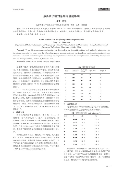
多弧离子镀是一种新型涂层制备的物理气相沉积技术,以靶材作阴极,设备内部壳体作阳极,在二者之间通过孤光放电,使得靶材上材料蒸发,并离化成空间等离子体与设备内气体相互扩散、反应,沉积在基体表面,形成薄膜。
该技术具备很高的沉积速率,制备涂层有较强的附着力,并且非常致密,操作便捷。
目前主要应用在高速钢和硬质合金零件上的TiN、Ti-A1-N耐磨层和TiN仿金装饰涂层[1]。
Ti-Al-N三元化合物涂层是近十年来科学研究的新宠,是在工业上常用TiN涂层上,添加Al元素得到性能更加优异的涂层。
Ti-Al-N涂层中具有代表性的Ti2AlN和Ti4AlN3化合物,既有比较高的切削性能、良好的导热导电性等金属特征,又有优异的抗高温氧化性能和耐腐蚀性等陶瓷特征,使其工件寿命大幅度延长,适合各种特殊条件下工作,加上其制样成本较低,Ti-Al-N涂层有很好的发展前景[2-3]。
1 试验方法本文采用多弧离子镀技术,使用T i∶A l=1∶1的靶材,氩气保护氛围下,通入一定量的氮气,在20mm×15mm×2mm的06Cr18Ni9不锈钢沉积镀膜。
通过美国EDAX-FOCAU2能量分散谱仪对涂层进行元素分布分析,并通过JSM-5500LV扫描电子显微镜测量涂层的厚度。
多弧离子镀沉积设备是沈阳真空镀膜设备有限公司生产。
本试验主要有负偏压、靶电流、沉积时间、氮气通量4个工艺参数,通过改变其中任一参数均会对涂层沉积状态有相应的影响,且各因素之间也会有相互的影响[4]。
为了更加科学严谨地观察4个工艺参数对涂层状态的影响,因此选用了正交试验的设计方法来设计试验,本研究建立了四因素三水平的正交试验表如表1所示。
表1 镀膜设计正交试验因素负偏压/V氮气通量/sccm时间/min靶电流/A 1200202070 2200404075 3200606080 4300204080 5300406070 6300602075 7400206075 8400402080 94006040702 结果与分析通过对沉积后的9组试样微区成分进行了检测分析,对沉积态薄膜的成分进行分析结果如表2所示。
VITA 3D-MASTER比色系统精品文档
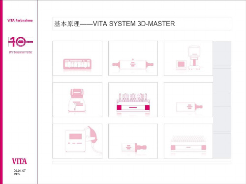
• VITAVM® CC
09.01.07 MP5
VITA 色彩复制
• VITA Vacumat 4000 触摸屏 -全自动烤瓷炉链接VITA 图 片浏览器 - 通过USB数据线链接观看病 人的照ห้องสมุดไป่ตู้-
09.01.07 MP5
VITA SYSTEM 3D-MASTER
内容: VITA 色彩传递过程: • VITA比色 • 色彩交流 • 色彩复制 • 色彩控制
09.01.07 MP5
VITA 色彩复制
• VITA PHYSIODENS树脂牙 -树脂牙颜色稳定 -丰富色彩选择
• VITAPAN树脂牙– -树脂牙颜色稳定 -耐磨性高
09.01.07 MP5
VITA 色彩复制 • VITA LINGOFORM 后牙
- 即使是个性化的打磨,颜色稳定性还是很好。
0M2 0.5M2 1M2 1.5M2 2M2 2.5M2 3M2 3.5M2 4M2 4.5M2 5M2
0M2.1 0.5M2.5
1.5M2.5 2M2.5 2.5M2.5 3M2.5 3.5M2.5 4M2.5 4.5M2.5 5M2.5
0M3
2M3 2.5M3 3M3 3.5M3 4M3 4.5M3 5M3
基本原理——VITA SYSTEM 3D-MASTER
09.01.07 MP5
VITA SYSTEM 3D-MASTER
09.01.07 MP5
Vita 比色
Vita 颜色传达
Vita 颜色复制
Vita 颜色控制
VITA SYSTEM 3D-MASTER
內容 VITA 色彩传递过程 • VITA比色 • 色彩交流 • 色彩复制 • 色彩控制
粉末涂料喷涂的变色系统(英文)

Color ChangeThe most commonly asked question regarding color change is, “how much time does it take?” The answer to this question depends on the following:•Type of booth, manual or automatic system.•Number of booths.•Spray-to-waste.•Type of recovery system, cyclone separator or cartridge booth.•Type of booth canopy.•Type of powder gun.•Number of powder guns.Additional color change variables:•How many people will do the color change?•What color(s) are you using?•How well trained are the operators?•What level of quality is needed?•Are you looking at the right equipment for color change?Because there are so many variables with color change, you should take steps to investigate all aspects of a color change system. Be leery when an equipment supplier remarks about how quickly certain color change systems perform. For instance, color change time on identical systems in different situations can vary. You can have the best powder coating system, but when it gets down to it, “people make the difference,”and can make the difference in the time it takes to make a color change.Spray-to-Waste Color Change SystemsWhen the production line is temporarily shut down, the time it takes to change color, will affect your cost of doing business. Spray-to-waste systems are very popular because they are very fast. The time it takes to change color is similar to the time it takes to clean out the gun.The design of the gun(s), pump(s), and hopper(s) should be of a modular construction for fast, easy disassembly for color change. In some cases, you can have additional hoppers or box feed units that will give you almost instant capabilities to change colors. I recommend before making an equipment purchase to take the gun(s) and pump(s) apart to see how easy they are to service and clean. There are guns available that do not require disassembly tools, which makes servicing and color change easier.Spray-To-Waste Color Change BoothsSpray-to-waste color change booths are a lot like a liquid paint system where 30 to 70 percent of the paint is thrown away. Normally, powder booths are designed to allow the workpiece to pass through a recovery area where powder is contained and used again. A spray-to-waste color change system will contain the powder and in some cases, will pump the overspray powder to a scrap container for disposal. There are several good reasons why spray-to-waste booths are in use today.•Number of colors and the time it takes to change colors.•Lost production time can be 30 to 60 minutes.•Short runs of various colors.•Ability to test a new color or powder from a different material supplier.The two most commonly used spray-to-waste booths are batch booths (Figure 1), and for larger operations, booths that incorporate roll-away filter modules for scrap colors (Figure 2).Note: First-pass transfer efficiency is extremely importantwhen spraying to waste.Figure 2Cartridges vs. CyclonesIn North America, the two most commonly used booths in the powder finishing industry are a cartridge booth that uses a roll-away cartridge filter module (Figure 3) and a conventional cyclone separator that uses a cartridge collector for a final filter (Figure 4).Booth CanopyCartridges or cyclones can use the same type of booth canopy. The booth canopy should be sturdy, easy to clean and maintain. Reasons for the booth canopy are:•Powder containment.•Enhanced transfer efficiency.•Color change.Powder is applied with an electrostatic charge, and the objective is to obtain a high, first-pass transfer efficiency.We want the powder attracted to the parts and not to the booth canopy. The canopy design is an important factor to the total integration of a powder coating system. The four most popular booth canopies are polypropylene,stainless steel, a combination of polypropylene and stainless steel, and painted steel.The most common canopy is the rigid polypropylene. It was first introduced in the early 80s and has grown to become the preferred canopy design. The polypropylene canopy has a translucency that improves visibility inside the booth and enhances gun transfer efficiency. It has a long wearing, smooth, slick surface that is easy to clean and does not attract powder or static build up. This is the most expensive booth material available.The second canopy design is made out of stainless steel and is durable and solid. Although not as easy to clean as a polypropylene booth, it is less expensive.A third canopy design is comprised of a combination of polypropylene and stainless steel. The polypropylenepanels are located around the gun slots and the roof in the booth. Again, it is an economical option.Lastly, the fourth canopy design is made of painted steel.The painted steel canopy is actually the earliest design, but after a few years and many color changes, it looses its appearance. It is durable and solid but not as easy to clean as the polypropylene or stainless steel canopies.Booth air flow and gun placement are critical factors in how well the booth will perform. In a powder coating system, “more is not better.” Air flow must contain the powder and not allow it to migrate through the opening.At the same time, however, the powder must reach the part. Optimal air flow will enhance the coating transfer efficiency. The powder coating gun should be positioned completely within the spray booth. What this means, is the grounded booth wall, whether it's conductive or non-conductive material, will be far enough from theelectrostatically charged tip of the gun to eliminate any disturbances. Furthermore, booth walls and floors should be smooth and free of joints. When it’s time to change color, the entire inside of the booth will need wiping down to remove excess powder. It is critical that all inside areas of the booth are visible to the naked eye for cleaning.Hidden areas, such as tight angles and enclosures, make color change difficult and more time consuming.Color ChangeThe cartridge booth (Figure 5) recovers oversprayed powder by means of a self-cleaning cartridge contained within a removable color module. When a color change is required, the pumps, hoses, guns, and booth canopy are cleaned, powder deposited into the color module, and then replaced with the next color module. Painting can then resume. As with all other types of booths, the clean-ing of the pumps, guns, and booth is completed with the fan motor in operation so the powder can be collected into the color module.The cyclone booth (Figure 6) requires all the steps of a cartridge booth, and in some cases, cleaning of the duct-work and lower one-third of the cyclone. In general, color change for the cartridge booth is much quicker and easierthan the conventional cyclone.Figure 3Figure 4Figure 5Figure 6Multi-Booth Operation and Color ChangeUp to this point, the discussion has focused on color change of a single powder spray booth. A multi-booth system might be the answer for your powder line. If your paint operation has many color changes and your produc-tion line is down for the color change, your operational costs will also change. More than one booth can save you money by reducing the amount of time your production line is down. There are many ways to get better use from your powder system. Let’s discuss ways color change can be accomplished.•Short Runs of Various Colors. Figure 7 shows a manual booth with two manual operators running short produc-tion runs. At the same time, the automatic booth is being prepared for its next color. The oversprayed pow-der in the manual booth is not saved because the length of time to clean this unit makes it cost prohibitive.•Two-Booth System/Automatic and Manual Touch Up. Figure 8 shows an on-line/off-line two-booth system. While the on-line booth is operating, the off-line booth is prepared for painting.Once the first color run is completed, the operator creates a temporary break in the line that allows the first color booth to roll off line and the next color booth to be rolled into position (Figure 9).As the break in the line passes, the second color booth then begins its painting run (Figure 10).Figure 7 Figure 8Figure 9 Figure 10While the second booth is operating, the first booth is cleaned and prepared for the next color. The entire color change process from a production standpoint takes only a few moments. This is a very practical way to color change quickly and efficiently when production parameters require it (Figure 11).•Multiple Conveyors/Booth. Another way color change can be accomplished very quickly is by installing a con-veyor that branches into different dedicated color booths (Figure 12). As parts move along the conveyor, they are directed to the proper color booth for painting. This design allows for more than one color to be applied to different parts simultaneously.Figure 11Figure 12SummaryThe success of a powder coating operation is determined by the quality and efficiency of recovered powder and how quickly a color change is accomplished. Over the last 20 to 30 years, many changes have taken place in the technology of recovery and reclaim systems. Equipment suppliers are constantly working to improve the efficien-cies of their equipment. As we move toward higherfirst-pass transfer efficiency, color change will be less of an issue.。
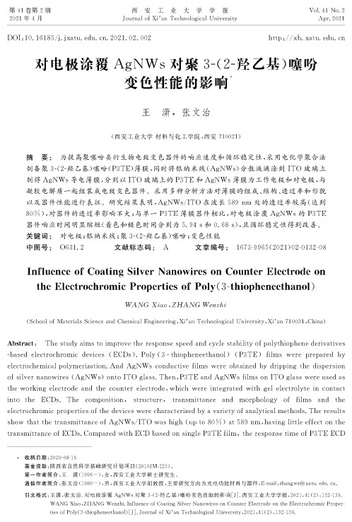
对电极涂覆AgNWs对聚3-(2-羟乙基)噻吩变色性能的影响
第41卷第2期2021 年4 月西 安 工 业 大 学 学 报JournalofXi 'anTechnologicalUniversityVol. 41 No. 2Apr2021DOI : 10. 16185/j. jxatu. edu. cn. 2021. 02. 002http : //xb. xatu. edu. cn对电极涂覆AgNWs 对聚3-(2-羟乙基)噻吩变色性能的影响** 收稿日期:2020-08-16基金资助:陕西省自然科学基础研究计划项目(2019JM-225)。
第一作者简介:王 潇(1996-),女,西安工业大学硕士研究生。
通信作者简介:张文治(1980-)男,西安工业大学副教授,主要研究方向为光电功能材料与器件,E-mail :zhangwz @xatu. edu. cn 。
引文格式:王潇,张文治.对电极涂覆AgNWs 对聚3-(2-羟乙基)噻吩变色性能的影响西安工业大学学报,2021,41(2):132-139.WANG Xiao,ZHANG Wenzhi. Influence of Coating Silver Nanowires on Counter Electrode on the Electrochromic Proper ties of Poly(3-thiopheneethanol ) )J]. Journal of Xi an Technological University , 2021,41(2) : 132-139.王潇,张文治(西安工业大学材料与化工学院,西安710021)摘要:为提高聚噻吩类衍生物电致变色器件的响应速度和循环稳定性,采用电化学聚合法制备聚3-(2-^乙基)噻吩(P3TE )薄膜,同时将银纳米线(AgNWs )分散液滴涂到ITO 玻璃上制得AgNWs 导电薄膜,分别以ITO 玻璃上的P3TE 和AgNWs 薄膜为工作电极和对电极,与凝胶电解质一起组装成电致变色器件。
elinchrom爱玲珑网站资料

Imagine positioning yourself at the bottom of an icy crevasse with a studio flash system, waiting for skiers to leap above you ! That was Tristan Shu’s crazy idea. The ELB 400 flash system was part of the winning formula for this exceptional photo shoot.想象一下自己和一个摄影棚闪光灯系统一起呆在一个冰冷的裂缝底部,等待滑雪者在你上空飞跃!这就是特里斯坦舒的疯狂的想法。
该ELB400闪光系统是这个特殊的照片拍摄的制胜法宝的一部分。
The French extreme sports photographer, Tristan Shu, tells us about his experiences with the new elinchrom portable battery flash system, the ELB 400. Shooting in freezing, dangerous, and snowy conditions, with a seemingly endless series of challenges to overcome, the results speak for themselves: bold and epic.法国极限运动摄影师,特里斯坦舒,向我们讲述了他和新爱玲珑便携式电池闪光系统在危险的风雪的条件中使用ELB400拍摄凝固画面的经历,这是很有挑战的项目,这也将是将是大胆和史诗级的挑战。
Tristan, tell us about how this crazy idea came to you.Tristan,跟我们说说为什么有这个疯狂的想法I actually shot something similar a few years ago. I had gone down into a crevasse and skiers were jumping above me and making shapes. At the time I had shot everything with natural lighting, and I said to myself that it would be cool to redo this shot with flash; the results with the vivid ice would be awesome. But it still took me years before I could pull everything together in the right conditions.其实我几年前曾经拍摄类似的东西。
Eclipse 使用说明书

Copyright© Interacoustics A/S:版权所有。
本文档中的信息归 Interacoustics⅍专有。
本文档中的信息如有更改,恕不另行通知。
未经 Interacoustics A/S事先书面许可,不得以任何方式或手段复制或传播本文档的任何部分。
目录1简介 (1)1.1关于本手册 (1)1.2使用说明 (2)1.2.1预期的操作人员 (2)1.2.2患者人群 (2)1.2.3禁忌症 (2)1.3产品说明 (3)1.4警告 (4)1.5故障 (5)2开箱和安装 (6)2.1检查 (6)2.2标记 (7)2.3硬件安装 (8)2.3.1将病床 /椅子放在地上 (9)2.3.2Eclipse 后面板 (10)2.3.3Eclipse前部面板 (10)2.3.4前置放大器按钮 (11)2.4软件安装 (11)2.4.1安装前须知 (11)2.4.2计算机系统最低要求 (11)2.4.3所需材料: (12)2.4.4软件安装 (12)2.4.5驱动程序安装 (13)2.4.6恢复软件出厂默认设置 (13)2.4.7安装语言包 (13)2.5识读台 (15)2.6许可证 (15)2.6.1Eclipse序列号 (15)2.6.2DSP序列号和许可证密钥 (15)2.7从 OtoAccess® 数据库启动 (16)2.7.1OtoAccess® 数据库中的模块设置 (16)2.8从Noah启动(仅 ASSR 或 IA OAE Suite) (17)3EP15/EP25操作说明 (18)3.1记录标签 (19)3.1.1主菜单项 (19)3.1.2电子帮助 (20)3.1.3查看历史会话 (20)3.1.4协议选择 (20)3.1.5临时设置 (20)3.1.6重新排列曲线 (20)3.1.7波形分组 (20)3.1.8报告 (20)3.1.9打印 (21)3.1.10显示A-B曲线 (21)3.1.11显示对侧曲线 (21)3.1.12授话 (21)3.1.13单曲线显示 (21)3.1.14分屏显示 (22)3.1.15保存并新建 (22)3.1.16保存并退出 (22)3.1.17刺激率选择 (22)3.1.18频率选择 (23)3.1.19刺激窗口 (23)3.1.20手动刺激窗口 (23)3.1.21状态窗口 (23)3.1.22波形再现性 (24)3.1.23开始/停止 (24)3.1.24暂停 (24)3.1.25下一强度 (24)3.1.26Fmp与残留噪声曲线图 (24)3.1.27扫描数/平均数的扩展 (25)3.1.28原始EEG (25)3.1.29高级EEG (25)3.1.30隐藏刺激伪影 (26)3.1.31显示增益 (27)3.1.32记录窗口 (27)3.1.33选择波形 (27)3.1.34移动单条曲线 (27)3.1.35显示微分曲线 (27)3.1.36为波形增添一条注释 (28)3.1.37拒收监测 (29)3.1.38放置波形标记 (29)3.1.39删除波形标记 (29)3.1.40建议波形标记 (30)3.1.41标准化潜伏期数据 (30)3.1.42删除单条曲线 (30)3.1.43放大/缩小单条曲线 (30)3.1.44隐藏单条曲线 (31)3.1.45固定单条曲线/与历史会话进行比较 (31)3.1.46合并曲线(创建加总曲线) (31)3.1.47添加曲线 (32)3.1.48同侧减对侧差值(Ipsi-Contra)曲线 (32)3.1.49A减B差值(A-B(N))曲线 (32)3.1.50修改显示滤波 (33)3.1.51记录的曲线状况 (33)3.1.52向曲线添加备注 (33)3.1.53使用光标 (34)3.1.54信噪比计算(3:1) (34)3.1.55CR、RA和INC波形标记 (34)3.2潜伏期标签 (35)3.2.1潜伏期值 (35)3.2.2潜伏期间值 (35)3.2.3潜伏期曲线图 (36)3.2.4显示波峰至波谷标记(SN10标记)(仅EPx5软件) (37)3.3Windows® 8, 10 和 11 无法启动帮助 (37)3.4电脑快捷键 (38)3.5测试前患者准备 (39)3.5.1阻抗检查 (39)3.5.2换能器 (39)3.6进行ABR阈值记录 (40)3.6.1电极画面 (40)3.6.2ABR阈值刺激 (40)3.6.3编辑ABR阈值记录 (41)3.6.4使用ABR阈值结果说明 (41)3.7进行神经潜伏期记录 (42)3.7.1电极画面 (42)3.7.2编辑神经潜伏期记录 (42)3.8进行eABR记录 (44)3.8.1两个推荐eABR电极画面 (44)3.8.2编辑eABR记录 (44)3.8.3电气阈值估算(用于人工耳蜗安接) (45)3.9进行ECochG记录 (46)3.9.1ECochG 电极安装 (46)3.9.2编辑ECochG记录 (48)3.10进行CM记录 (49)针对患者的准备工作至关重要 (49)3.10.1CM电极画面 (49)3.10.2用于CM记录的刺激 (49)3.10.3CM记录示例 (49)3.10.4CM结果内差值 (49)3.11进行AMLR记录 (50)3.11.1电极画面AMLR示例 (50)3.11.2可用AMLR刺激 (50)3.11.3AMLR记录示例 (51)3.12进行ALR记录/皮层ERA (52)3.12.1ALR阈值记录的电极画面示例 (52)3.12.2刺激信号 (52)3.12.3ALR结果说明 (53)3.12.4电生理阈值估算和婴幼儿听力仪器安接 (53)3.13进行P300/MMN记录 (54)3.13.1P300/MMN电极画面示例 (54)3.13.2可用P300/MMN刺激 (54)3.13.3P300和MMN参数汇总表 (55)3.14性能/环回(LBK15)测试 (55)4VEMP操作说明 (56)4.1前置放大器设置 (56)4.2VEMP监示器 (56)4.3VEMP波形标记 (57)4.4计算VEMP不对称率(VEMP伙伴) (57)4.5VEMP比例设定 (58)4.6进行cVEMP记录 (58)4.6.1用于cVEMP的电极画面 (58)4.6.2用于cVEMP的刺激 (59)4.6.3默认收集参数 (59)4.6.4程序 (59)4.6.5编辑cVEMP结果 (59)4.6.6cVEMP结果示例 (60)4.6.7cVEMP结果示例 (60)4.7进行oVEMP记录 (61)4.7.1oVEMP电极画面 (61)4.7.2用于oVEMP的刺激 (61)4.7.3默认收集参数 (61)4.7.4程序 (62)4.7.5oVEMP结果示例 (62)5研究模块 (63)5.1.1记录每次扫描(以便以后进行“中继”) (63)5.1.2导出平均曲线和/或完整会话 (64)5.1.3导出会话(所有曲线) (65)5.1.4离线导出波形 (65)5.1.5导入用于刺激的波形文件 (65)6操作说明 (69)6.1耳塞的操作和选择 (69)6.2OAE 设备的日常系统检查 (70)6.2.1探头完整性测试 (70)6.2.2真耳检查 (71)7.IA OAE Suite (72)7.1PC 电源配置 (72)7.2兼容的设备 (72)7.2.1从 OtoAccess® 数据库启动 (72)7.2.2从 Noah 4 启动 (72)7.2.3模拟模式 (72)7.2.4崩溃报告 (73)7.3使用菜单 (74)7.4使用 DPOAE 探头 (75)7.4.1准备测试 (75)7.4.2DPOAE 模块中的元素 (77)7.5使用 TEOAE 模块 (83)7.5.1准备测试 (83)7.5.2TEOAE 模块中的元素 (85)7.6使用打印向导 (90)8.ABRIS操作说明 (92)8.1使用ABRIS模块 (92)8.2安装电极 (92)8.3阻抗检查 (92)8.4回路(LBK15)测试 (93)8.5ABRIS测试屏幕 (93)8.5.1主菜单项 (93)8.5.2查看历史会话 (94)8.5.3保存并退出 (94)8.5.4打印 (94)8.5.5电子帮助 (94)8.5.6报告 (94)8.5.7查看EEG或噪声条 (94)8.5.8刺激窗口 (94)8.5.9测试状态窗口 (95)8.5.10受试耳 (95)8.6进行ABRIS记录 (96)8.6.1开始与暂停测试 (96)8.6.2EEG曲线图 (96)8.6.3EEG噪声条 (96)8.6.4AEP波形 (96)8.6.5备注框 (96)8.6.6状态栏 (97)8.6.7ABRIS反应曲线 (97)8.7电脑快捷键 (98)8.8可拆卸零部件 (98)9.ASSR操作说明 (99)9.1使用ASSR模块 (99)9.2ASSR测试前准备 (99)9.3测试前准备 (99)9.3.1皮肤准备 (99)9.3.2放置电极 (100)9.3.3阻抗检查 (100)9.4安装电极 (101)9.5阻抗检查 (101)9.6系统性能/回路(LBK15)测试 (101)9.7ASSR标签 (102)9.7.1主菜单项 (102)9.7.2协议选择 (102)9.7.3临时设置 (103)9.7.4报告 (103)9.7.5打印 (103)9.7.6保存并退出 (103)9.7.7查看历史会话 (103)9.7.8刺激窗口 (103)9.7.9总会话状态窗口 (104)9.7.10刺激率 (104)9.8进行ASSR记录 (105)9.8.1开始/停止 (105)9.8.2暂停 (105)9.8.3原始EEG曲线图 (105)9.8.4测试频率曲线图 (105)9.8.5CM 检测器 (106)9.8.6ASSR表 (106)9.8.7延长测试时间 (107)9.8.8调整刺激强度 (107)9.8.9中止测试频率/强度 (108)9.8.10ASSR 遮蔽计算器 (108)9.9听力图标签 (110)9.9.1估计的听力图符号 (110)9.9.2NOAH 或 OtoAccess® 数据库中的听力符号 (111)9.9.3估算听力图 (112)9.9.4AC 和 BC 在同一听力图中 (113)9.9.5无反应 (114)9.9.6选定的校正系数 (114)9.9.7电脑快捷键 (114)10.维护 (115)10.1通用维护程序 (115)10.2如何清洁国际听力产品 (115)10.3清洁OAE探头尖 (116)10.4关于维修 (117)10.5保修 (117)11.技术规格 (119)11.1技术规格 - Eclipse硬件 (119)11.2EP15/EP25/VEMP技术规格 (120)11.2.1peSPL至nHL校正值 (122)11.3TEOAE25技术规格 (123)11.4DPOAE技术规格 (124)11.5ABRIS技术规格 (125)11.6ASSR技术规格 (126)11.7电磁兼容性(EMC) (127)11.8Eclipse软件模块概览 (132)11.8.1EP15/EP25/VEMP模块 (132)11.8.2P15/EP25/VEMP模块刺激最大强度 (133)11.8.3TEOAE25模块 (134)11.8.4DPOAE模块 (134)11.8.5ABRIS模块 (134)11.8.6ASSR模块 (134)1简介1.1 关于本手册本手册适用于EP15/25 v4.6软件版本、IA OAE套件1.2、ABRIS v1.6.3、VEMP v4.6和ASSR v 1.3。
钙钛矿结构及相关功能材料

钙钛矿结构中基本的 (AO3)4- (111) 面的密堆层
2)结构特点:
氧八面体共顶点连接,组成三维网络,根据Pauling的配位多面体连接规则,此种结构比共棱、共面连接稳定。 共顶连接使氧八面体网络之间的空隙比共棱、共面连接时要大,允许较大尺寸离子填入,即使产生大量晶体缺陷,或者各组成离子的尺寸与几何学要求有较大出入时,仍然能够保持结构稳定;并有利于氧及缺陷的扩散迁移。
磁性金属多层膜GMR效应
图 Co/Cu多层膜的磁电阻与Cu层厚度tCu的关系曲线
Co/Cu多层膜的磁电阻与Cu层厚度tCu为0.9、1.9、3.0nm处,分别有一明显的峰值,对应反铁磁耦合,谷对应铁磁耦合。随着非磁层厚度的变化,多层膜中磁层的层间耦合在反铁磁与铁磁间振荡,磁电阻值也在极大与极小间振荡。
对于自发极化而言,从宏观统计来看,晶体中存在着各个方向的自发极化和电畴,它们相互抵消,宏观上对外不呈现极性。
外电场作用时,沿电场方向极化畴长大,逆电场方向的畴消失,其它方向分布的电畴转到电场方向,极化强度随外加电场的增加而增加,一直到整个结晶体成为一个单一的极化畴为止。如再继续增加电场只有电子与离子的极化效应,和一般电介质一样。
在机械应力的作用下介质发生极化,形成晶体表面电荷的效应称为压电效应。
01
反之,当外加电场于晶体,晶体发生形变的效应称为逆压电效应。逆压电效应也称电致伸缩效应。这样的性质称为晶体的压电性。具有压电效应的晶体称为压电体。
02
热释电效应:具有自发极化的晶体在温度发生变化,其极化状态的发生改变,使电介质对外显电性。
在La2/3Ca1/3MnO3中,低价态Ca的掺入,使得Mn采取+3和+4的混合价态,从而满足钙钛矿结构的电价要求。在Ca2CaUO6中,有1/3的Ca与U交替占据钙钛矿型晶格的B位。在Ba2Bi2O6中,有一半Bi原子为+3价,另一半为+5价。
scanner的科学价值

如新华茂生物光子扫描仪
史上第一个非侵入性
测量抗氧化剂的方法
The first non-invasive consumer test to measure antioxidant statusin vivo
●获诺贝尔物理奖的诺曼分光法 ●美国犹他大学 ●耗资2600万美金耗时6年研发
Biophotonic Scanner
Bio = 生命, 生物 Photonic = 光的 Biophotonic = 藉由光的能量来 测量生物有机体
➢ 利用拉曼光谱原理, 历时六年研发 ➢ 花费美金7000万, 独有专利至2020年
类胡萝卜素的化学结构
➢ 类胡萝卜素可提供自由基大量电子 ➢ 抵抗自由基攻击的第一线营养素
✓ 与血液类胡萝卜素之间具高度关联性 ✓ 与其它血液中抗氧化物(如Vit C & E)之间具高度
关联性 ✓ 与氧化压力(自由基伤害)具高度逆关联性
➢ 生物光子扫描仪检测身体类胡萝卜 素与测量血液一样可靠!
哈佛大学 / 史丹佛大学 联合皮肤临床试验 - 1
哈佛大学 / 史丹佛大学 联合皮肤临床试验 - 2
与血糖检测仪的准确度比较
抗氧化权威医生Dr. James Balch服 用如沛前后指数差别
35,000
32,000
35,000
30,000 25,000 20,000
20,000
25,000
15,000
10,000
5,000
0
0 week
3 weeks
4 weeks
10 weeks
Dr. Balch服用抗氧化剂产品己长达20年,
抗氧化指数
健康航标,告诉人们自己离疾病还有多远, 建立预防意识,远离慢性疾病。
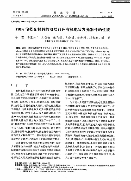
TBPe作蓝光材料的双层白色有机电致发光器件的性能
第2 7卷
第 4期
发 光 学 报
CHI NES OURNAL UM I EJ OF L NES CENCE
Vo_ 7 Leabharlann . l2 o4 A g ,2 0 u . 06
20 0 6年 8月
文章编 号 : 007 3 (0 6 0 -570 10 -0 2 20 )40 3 -6
项目
作者简介 :牛霞(9 0一), ,天津 人,硕士研究生 ,主要从事有机 电致发光器件制备的研究。 18 女 }:通 讯 联 系人 ;E m i uih a t teu c , e:( 2 )2 6 99 - al l u@ j .d . a T l 0 2 3 7 70 :y n u
巧妙结 合 , 明显 地 简 化 了 器件 的 制 作 工序 , 提 高 了器 件 的稳 定性 和 可重 复性 。
大多数有机 电致 发光材料是单极性 的, 或者 具有传输空穴的性质 , 或者具有传输 电子的性质 ,
同时具 有均 等 的空穴 和 电子传输 性质 的有 机物 很 少 。单 极性有 机 物 作 为单 层 器件 的发 光 材 料 时 , 电子与 空穴 的复合 区越 靠 近 电极 就越 容易 被该 电
且随着外加电压的变化 , 色坐标基本保持不 变 , 在外 加驱动 电压 为 1 6 V时 , 器件 的亮度 为 78c/ 外量子 3 d m , 效率为 0 2 。我们还尝试选用本身可 以发绿 白光 , .% 而且兼具 电子传输特性 的母体材料 Z ( T ) n B Z 替代 A q , l 器件 的最大亮度提高到 1 0 d m , 0c/ 色坐标 为( . 2 0 3 ) 更加 接近 白色等能 点 , 件其他 光 电性 能也得 3 0 3 , .6 , 器
Overview of Single-Phase Grid-Connected Photovoltaic Systems
Overview of Single-Phase Grid-Connected Photovoltaic SystemsYang, Yongheng; Blaabjerg, FredePublished in:UEMP, Electric Power Components and SystemsDOI (link to publication from Publisher):10.1080/15325008.2015.1031296Publication date:2015Link to publication from Aalborg University - VBNSuggested citation format:Y. Yang and F. Blaabjerg, ''Overview of Single-Phase Grid-Connected Photovoltaic Systems,''Electric Power Components and Systems,in press, DOI: 10.1080/15325008.2015.1031296, pp. 1-10, 2015.General rightsCopyright and moral rights for the publications made accessible in the public portal are retained by the authors and/or other copyright owners and it is a condition of accessing publications that users recognize and abide by the legal requirements associated with these rights.Users may download and print one copy of any publication from the public portal for the purpose of private study or research.You may not further distribute the material or use it for any profit-making activity or commercial gain.You may freely distribute the URL identifying the publication in the public portal.Take down policyIf you believe that this document breaches copyright please contact us at vbn@aub.aau.dk providing details, and we will remove access tothe work immediately and investigate your claim.Downloaded from vbn.aau.dk.Overview of Single-Phase Grid-Connected Photovoltaic SystemsYongheng Yang, Frede BlaabjergA still booming installation of solar photovoltaic (PV) systems has been witnessed worldwide. Itis mainly driven by the demand of “clean” power generation. Grid-connected PV systems will become an even active player in the future mixed power systems, which are linked by a vast of power electronics converters. In order to achieve a reliable and efficient power generation from PV systems, stringent demands have been imposed on the entire PV system. It in return advances the development of power converter technology in PV systems. This paper thus takes an over-view of the advancement of power electronics converters in single-phase PV systems, being commonly used in residential applications. Demands to single-phase grid-connected PV systems as well as the general system control strategies are also addressed in this paper.Keywords: photovoltaic systems; power converters; transformerless; single-phaseSubject classification: power electronics convertersI.INTRODUCTIONTraditional power generations that are on a basic of fossilfuel resource are considered to be unsustainable in long-term national strategies. This has been one of the maindriving forces for an increasing installation of renewableenergies like wind power, solar PhotoVoltaic (PV) power,hydropower, biomass power, geothermal power, and oceanpower, etc. into the public grids [1], [2]. Among the majorrenewables, the solar PV power generation has continuedto expand at a rapid rate over the past five years (growth inglobal capacity averaging almost 55% annually) [3], [4].As an extreme example, in Italy, 7.8% of the annual totalelectricity demand was covered by solar PV systemsthroughout 2013 [4]. In Germany, there has been around 36 GW installed by the end of 2013, where most of the PV systems are residential applications [4]-[7]. Fig. 1 further illustrates the worldwide solar PV evolution in the past years [7], which shows increasingly worldwide expecta-tions from energy production by means of solar PV power systems. Therefore, as the typical configuration for resi-dential PV applications, the single-phase grid-connected PV systems have been in focus in this paper in order to describe the technology catering for a desirable PV inte-gration into the future mixed power grid.Power electronics technology has been witnessed as the enabling technology for more renewable energies in the grid, including solar PV systems [8]. Associated by the advancements of power semiconductor devices [9], the power electronics part of the entire PV systems (i.e., power converters) holds the responsible for a reliable and effi-cient energy conversion from the clean, pollution-free, and inexhaustible solar PV energy. As a consequence, a vast of grid-connected PV power converters have been developed and commercialized widely [10]-[15].Fig. 1. Evolution of global accumulative photovoltaic capacity (Giga-Watts) from 2000 to 2013 and an estimation until 2018 in a medium scenario based on the data available on-line from . However, the grid-connected PV systems vary signifi-cantly in size and power – from small scale DC module (a few hundred watts) to large scale PV power plant (up to hundred Mega-Watts). In general, the PV power converters can simply be categorized into: module-, string-, multi-string, and central converters. The multi-string and central converters are intensively used for solar PV power plants/farms as three-phase systems [16]-[18]. In contrast, the module- and string-converters are widely adopted in residential applications as single-phase systems [19], [20]. Although the PV power converters are different in configu-ration, the major functions of the power converters are the same, including PV power maximization, DC to AC power conversion and transfer, synchronization, grid code com-pliance, reactive power control, islanding detection and protection, etc. [8], [21]. It also requires advanced and in-telligent controls to perform these PV features and also tomeet customized demands, where the monitoring, forecast-ing, and communication technology can enhance the PV integration [18], [21].As aforementioned, the PV systems are still dominant in the residential applications, and will be even diversely spread out in the future mixed grid. Thus, the state-of-the-art developments of single-phase grid-connected PV sys-tems are selectively reviewed in this paper. Focus has been put on the power converter advancements of single-phase grid-connected PV systems for residential applications. Demands from the grid operators and the consumers to single-phase PV systems are firstly introduced in § II. In order to meet the increasing demands, the general control structures of single-phase grid-connected PV systems are presented in § IV before the conclusion.II.DEMANDS FOR GRID-CONNECTEDPHOTOVOLTAIC SYSTEMSThe grid-connected PV systems are being developed at a very fast rate and will soon take a major part of power electricity generation in some areas [22], [23]. At the same time, the demands (requirements) to the PV systems as shown Fig. 2 are becoming much tougher than ever before. Although the power capacity of a PV system currently is still not comparable to that of an individual wind turbine system, similar demands to wind turbine systems are being transitioned to the PV systems [18], [21], since the number of large-scale PV systems (power plants) is continuously increased [24].Fig. 2. Demands (challenges) for a grid-connected PV system based onpower electronics converters. Nevertheless, the demands for PV systems can be speci-fied at different levels. At the PV side, the output power of the PV panels/strings should be maximized, where a DC-DC converter is commonly used, being a double-stage PV system. This is known as the Maximum Power Point Tracking (MPPT). In this case, the DC voltage (DC-link voltage) should be maintained as a desirable value for the inverter. Moreover, for safety (e.g., fire), the panel moni-toring and diagnosis have to be enhanced at the PV side [25]. At the grid side, normally a desirable Total Harmonic Distortion (THD) of the output current should be attained (e.g., lower than 5%) [26]. In the case of large-scale PV systems with higher power ratings, the PV systems should not violate the grid voltage and the grid frequency by means of providing ancillary services (e.g., frequency reg-ulation). Additionally, the PV systems have to ride-through grid faults (e.g., voltage sags and frequency changes), when a higher PV penetration level comes into reality [18], [21], [27]-[33].Since the power capacity per generating unit is relative low but the cost of energy is relative high, there are always strong demands for high efficiency in order to reduce the cost of PV energy. In respect to efficiency, the power elec-tronics system (including passive components) counts for the most of power losses in the entire PV system. Thus, possibilities to meet the efficiency demand include using advanced semiconductor devices, intelligent control, and power lossless PV topologies. Transformerless PV tech-nology is an example, and the transformerless PV inverters can achieve a relatively high conversion efficiency when the isolation transformers are removed [11], [26]. Howev-er, minimizing the ground current in these transformerless PV converters is mandatory for safety [11]. Moreover, reliability is of much importance in the power electronics based PV systems, as shown in Fig. 2. This is motivated by extending the total energy production (service time) and further reducing the cost of energy [8], [34]-[36]. Finally, because of exposure or smaller housing chamber, the PV converter system (power electronics system) must be more temperature insensitive (i.e. with temperature manage-ment), which is also beneficial for the reliability perfor-mance. As it has been illustrated in Fig. 2, advancing the monitoring, forecasting, and communication technologies is crucial to implement future grid-friendly PV systems into a mixed power grid.III.POWER CONVERTER TECHNOLOGYFOR SINGLE-PHASE PV SYSTEMSAccording to the state-of-the-art technologies, there are mainly four configuration concepts [2], [10], [37], [38] to organize and transfer the PV power to the grid, as it is shown in Fig. 3. As it can be seen in Fig. 3, each of the grid-connected concepts consists of series of paralleled PV panels or strings, and they are configured by a couple of power electronics converters (DC-DC converters and DC-AC inverters) in accordance to the output voltage of the PV panels as well as the power rating.A central inverter is normally used in a three-phase grid-connected PV plant with the power larger than tens of kWp, as it is shown in Fig. 4. This technology can achieve a relatively high efficiency with a lower cost, but it re-quires high voltage DC cables [10]. Besides, due to its low immunity to hotspots and partial shading, power mismatch issue is significant in this concept (i.e. low PV utilization). In contrast, the MPPT control is achieved separately in each string of the string/multi-string PV inverters, leading to a better total energy yield. However, there are still mis-matches in the PV panels of each string, and the multi-Fig. 3. Grid-connected PV system concepts: (a) AC-module PV system, (b) string inverter system, (c) multi-string inverter system, and (d) central PVinverter topology.Fig. 4. Large-scale PV power plant/station based on central inverters forutility applications, where multi-level converters can be adopted as the central inverters to handle even higher power up to tens of Mega-Watts. Fig. 5. Single-phase grid-connected PV systems, where the AC-module inverters, the string inverters, and the multi-string inverters are commonly used: (a) with a low-frequency (LF) transformer, (b) with a high-frequency (HF) transformer, and (c) without transformers. string technology requires more power electronics convert-ers, resulting in more investments. Considering the above issues, the module converters (DC-module converters and/or AC-module inverters) are developed, being a flexi-ble solution for the PV systems of low power ratings and also for module-level monitoring and diagnostics. This module integrated concept can minimize the effects of par-tial shadowing, module mismatch, and different module orientations, etc., since the module converter acts on a sin-gle PV panel with an individual MPPT control. However, the low overall efficiency is the main disadvantage of this concept.It can be seen in Fig. 3 that the module concept, the string inverter, and multi-string inverters are the most common solutions used in single-phase PV applications, where the galvanic isolation for safety is one importance issue. Traditionally, an isolation transformer can be adopt-ed either at the grid-side with low frequencies or as a high frequency transformer in such PV converters, as it is shown in Fig. 5(a) and (b). Both grid-connected PV tech-nologies are available on the market with an overall effi-ciency of 93-95% [26], to which is mainly contributed by the bulky transformers. In order to increase the overall efficiency, a vast of transformerless PV converters have been developed [10], [11], [26], which are selectively re-viewed in the following.A.Transformerless AC Module Inverters (Module Inte-grated PV Converters)In the last years, much more efforts have been devoted to reduce the number of power conversion stages in order to increase the overall efficiency, as well as increase the power density, being the single-stage AC-module PV in-verters. By doing so, the reliability and thus the cost can be reduced. Fig. 6 shows the general block diagram of a sin-gle-stage grid-connected AC-module PV topology, where all the desired functionalities shown in Fig. 2 have to be performed. It should be noted, the power decoupling in such a single-stage topology is achieved by means of a DC-link capacitor, C dc, in parallel with the PV module[10], [11].Fig. 6. General block diagram of a single-stage single-phase PV topology(AC module/string inverter system).Fig. 7. A universal single-stage grid-connected AC-module inverter with an LCL-filter based on the concept proposed by B.S. Prasad, etc. appeared in IEEE Trans. Energy Conversion – 23(1), p. 128-137, Mar. 2008. Since the power of a single PV module is relative low and is strongly dependent of the ambient conditions (i.e., solar irradiance and ambient temperature), the trend for AC-module inverters is to integrate either a boost or abuck-boost converters into a full-bridge or half-bridge in-verter in order to achieve an acceptable DC-link voltage [39]-[45]. As it is presented in [39], a single-stage module integrated PV converter can operate in a buck, boost, or buck-boost mode with a wide range of PV panel output voltage. This AC-module inverter is shown in Fig. 7, where an LCL-filter is used to achieve a satisfactory total harmonic distortion of the injected current. A variant AC-module inverter has been introduced in [40], which is however a resultant integration of a boost converter and a full-bridge inverter. The main drawback of the integrated boost AC-module inverter is that it will introduce a zero-cross current distortion. In order to solve this issue, the buck-boost AC module inverters are preferable [41]-[44]. Fig. 8 shows two examples of the buck-boost AC-module inverter topologies for single-phase grid-connected PV applications. In the AC-module inverter shown in Fig. 8(a), each of the buck-boost converters generates a DC-biased unipolar sinusoidal voltage, which is 180° out of phase to the other, so as to alleviate the zero-cross current distortions. Similar principles are applied to the buck-boost integrated full-bridge inverter, which operates for each half-cycle of the grid voltage. However, as shown in Fig. 8(b), this AC-module inverter is using a common source. In addition to the above topologies that are mainly based on two relatively independent DC-DC converters integrat-ed in an inverter, other AC-module inverters are proposed in the literature. Most of these solutions are developed in accordance to the impedance-admittance conversion theory as well as an impedance network [46]-[50]. The Z-source inverter is one example, which is able to boost up the volt-age for a full-bridge inverter by adding an LC impedance network, as shown in Fig. 9. Notably, the Z-source inverter was mostly used in three-phase applications in the past. Fig. 8. Buck-boost integrated AC-module inverters with an LCL filter: (a) differential buck-boost inverter based on the concept proposed by N.Vazquez, etc. appeared in Proc. of APEC, pp. 801-806, 1999 and (b) buck-boost integrated full-bridge inverter based on the concept proposed by C. Wang appeared in IEEE Trans. Power Electron. -19(1), pp. 150 -159, 2004Fig. 9. Single-phase Z-source based AC-module inverter with an LCLfilter.Fig. 10. Single-phase transformerless full-bridge string inverter with an LCL filter, which also indicates the ground current circulating paththrough the parasitic capacitor C p.B.Transformerless Single-stage String InvertersThe above-discussed AC-module inverters with an inte-gration of a DC-DC boosting converter are suitable for use in low power applications. When it comes to higher power ratings (e.g., 1 ~ 5 kWp), the compactness of AC-module inverters is challenged. In such applications, the mostcommonly used inverter topology is the single-phase Full-Bridge (FB) string inverter due to its simplicity in terms of less power switching devices. Fig. 10 depicts the hardware schematics of a single-phase FB string inverter with an LCL filter, for a better power quality. It is also shown in Fig. 10 that a leakage current will circulate in the trans-formerless topology, requiring a specifically designed modulation scheme to minimize. Conventional modulation methods for the single-stage FB string inverter topology include a bipolar modulation, a unipolar modulation, and a hybrid modulation [26]. Considering the leakage current injection, the bipolar modulation scheme is preferable [26], [51]. Notably, optimizing the modulation patterns is an alternative to eliminate the ground (leakage) currents [52]. Fig. 11. Transformerless string inverters derived from the full-bridge inverter by adding a DC path: (a) H5 inverter topology proposed by M.Victor, etc., U.S. Patent 20050286281 A1, Dec 29, 2005. and (b) H6 inverter topology proposed by R. Gonzalez, etc., appeared in IEEE Trans.Power Electron. – 22(2), pp. 693-697, Mar. 2007. Transformerless structures are mostly derived from the FB topology by providing an AC path or a DC path using additional power switching devices. This will result in an isolation between the PV modules and the grid during the zero-voltage states, thus leading to a low leakage current injection. Fig. 11 shows two examples of single-stage transformerless PV inverters derived from the single-phase FB topology by providing a DC path [53], [54]. Thanks to the extra DC bypass, the PV strings/panels are isolated from the grid at zero-voltage states. Alternatively, the iso-lation can be achieved at the grid side by means of adding an AC path. As exemplified in Fig. 12(a), the Highly Effi-cient and Reliable Inverter Concept (HERIC) string invert-er [55] has the same number of power switching devices as that of the H6 inverter, but it provides an AC path to elimi-nate the leakage current injection. Similarly, the Full-Bridge Zero Voltage Rectifier (FB-ZVR) topology is pro-posed in [56], where the isolation is attained by adding a zero voltage rectifier at the AC side, as shown in Fig. 12(b).It should be pointed out that there are also many other transformerless topologies reported in the literature in ad-dition to the above solutions by means of adding an extra path [26], [52], [57]-[60]. Taking the Conergy string in-verter as an example, which is shown in Fig. 13, the single-phase transformerless string inverter can be developed based on the multi-level power converter technology [26], [58], [59].Fig. 12.Transformerless string inverters derived from the full-bridge inverter by adding an AC path: (a) highly efficient and reliability inverter concept (HERIC) topology proposed by H. Schmidt, etc., U.S. Patent 7046534, 2006 and (b) full-bridge with a zero voltage rectifier (FB-ZVR) proposed by T. Kerekes, etc. appeared in IEEE Trans. Ind. Electron. –58(1), pp. 184-191, Jan. 2011.Fig. 13. A transformerless string inverter derived from neutral point clamped topology – Conergy neutral point clamped inverter with an LCL filter based on the concept proposed by P. Knaup, International Patent Application, WO 2007/048420 A1, May 3, 2007.C.DC-Module Converters in Transformerless Double-Stage PV SystemsThe major drawback of single-stage PV topologies is that the output voltage range of the PV panels/strings is limited especially in low power applications (e.g. AC-module inverters), which thus will affect the overall effi-ciency. The double-stage PV technology can solve this issue since it consists of a DC-DC converter that is respon-sible for amplifying the PV module low voltage to a desir-able level for the inverter stage. Fig. 14 shows the general block diagram of a double-stage single-phase PV topology.The DC-DC converter also performs the MPPT control ofthe PV panels, and thus extended operating hours can be achieved in a double-stage PV system. The DC-link capac-itor C dc shown in Fig. 14 is used for power decoupling, while the PV capacitor C pv is for filtering.Fig. 14. General block diagram of a double-stage single-phase PV topolo-gy (with a DC-DC converter).In general, the DC-DC converter can separately be in-cluded between the PV panels and the DC-AC inverters that can be the string inverters discussed above or a simple half-bridge inverter. The following illustrates the double-stage PV technology consisting of a DC-DC converter and a full-bridge inverter. Fig. 15 shows a conventional dou-ble-stage single-phase PV system, where the leakage cur-rent has to be minimized as well. However, incorporating the boost converter will decrease the overall conversion efficiency. Thus, variations of the double-stage configura-tion have been introduced by means of a time-sharing boost converter or a soft-switched boost converter [61],[62]. The time-sharing boost converter shown in Fig. 16 isa dual-mode converter, where the switching and conduc-tion losses are reduced, leading to a satisfactory efficiency. Fig. 15. Conventional double-stage single-phase PV topology consisting of a boost converter and a full-bridge inverter with an LCL filter.Fig. 16. Double-stage single-phase PV topology using a time-sharing boost converter and a full-bridge inverter with an LCL filter based on the concept proposed by K. Ogura, etc., appeared in Proc. of IEEE PESC, pp.4763-4767, 2010.An alternative to improve the efficiency can be achieved using a DC-DC converter with parallel inputs and series outputs in order to process the source energy one and a half times instead of two times. This topology has been intro-duced in [63], and it is shown in Fig. 17. It should be pointed out that the voltage step-up gain of the DC-DC converter is also improved at the same time. In addition, the impedance network based DC-DC converters (e.g., the Z-source and Y-source networks) might be another promis-ing solution for single-phase double-stage PV systems, due to the high step-up voltage gain [64]-[67].Fig. 17. Double-stage single-phase PV topology with a parallel-input series-output bipolar DC output converter and a full-bridge inverter based on the concept proposed by R. West, U.S. Patent 2008/0037305 A1, Feb.14, 2008.IV.CONTROL OF SINGLE-PHASE GRID-CONNECTED PV SYSTEMSThe control objectives of a single-phase grid-connected PV system [68] can be divided into two major parts: a) PV-side control with the purpose to maximize the power from PV panels and b) grid-side control performed on the PV inverters with the purpose to fulfil the demands shown in Fig. 2. A conventional control structure for such a grid-connected PV system thus consists of two-cascaded loop in order to fulfil the demands [32], [68] – the outer pow-er/voltage control loop generates the current references and the inner control loop is responsible for shaping current, where thus the power quality is maintained, and also per-forming various functionalities, as shown in Fig. 18.Fig. 19 shows the general control structure of a single-phase single-stage grid-connected PV system, where the PV inverter has to handle the fluctuating power (i.e., MPPT control) and also to control the injected current ac-cording to the specifications shown in Fig. 18. As it can be observed in Fig. 19, the control can be implemented in both stationary and rotating reference frames in order to control the reactive power exchange with the grid, where the Park transformation (dq Æαβ) or inverse Park trans-formation (αβÆdq) are inevitable. In terms of simplicity, the control in the stationary reference frame (αβ-reference frame) is preferable, but it requires an orthogonal system to generate a “virtual” system, which is in-quadrature to the real grid. In the dq-reference frame, the MPPT control gives the active power reference for the power control loop based on Proportional Integrator (PI) controllers, which then generate the current references as shown in Fig. 19(b). The Current Controller (CC) in the dq-reference frame can be PI controllers, but current decoupling is required. In contrast, enabled by the single-phase PQ theory [32], [69], the reference grid current i*g can be calculated using the power references and the in-quadrature voltage system. In that case, the PI controller will give an error in the con-trolled grid current. The controller (i.e., CC) should beFig. 18. General control blocks (control objectives) of a grid-connected single-phase PV system.Fig. 19. General control structure of a single-phase single-stage full-bridge PV system with an LCL filter and reactive power injection capabil-ity (CC – Current controller, PLL – Phase locked loop): (a) hardware schematics, (b) control block diagrams in the dq-reference frame, and (c) control block diagrams in the αβ-reference frame. designed in the αβ-reference frame. For example, a Propor-tional Resonant (PR) controller, a Repetitive Controller (RC), and a Dead-Beat (DB) controller [68], [70]-[73] can directly be adopted as the CC shown in Fig. 19(c). Nota-bly, since the CC is responsible for the current quality, it should be taken into account in the controller deign and the filter design (e.g., using high order passive filter, LCL fil-ter). By introducing harmonic compensators [26], [32], [68], [70] and adding appropriate damping for the high order filter [74], [75], an enhancement of the CC tracking performance can be achieved. Similar control strategies can be applied to the double-stage system, as shown in Fig.20. The difference lies in that the MPPT control is imple-mented on the DC-DC converter, while the other function-alities are performed on the control of the PV inverter. There are other control solutions available for single-phase grid-connected PV systems [76]-[78]. For example, the instantaneous power is controlled in [77], where the syn-thesis of the power reference is a challenge; in [78], a one-cycle control method has been applied to single-stage sin-gle-phase grid-connected PV inverters for low power ap-plications.It should be noted that the injected grid current is de-manded to be synchronized with the grid voltage as re-quired by the standards in this field [68]. As a conse-quence, the grid synchronization as an essential grid moni-toring task will strongly contribute to the dynamic perfor-mance and the stability margin of the entire control system. The grid synchronization is even challenged in single-phase systems, as there is only one variable (i.e. the grid voltage) that can be used for synchronization. Neverthe-less, different methods to extract the grid voltage infor-mation have been developed in recent studies [26], [68], [79]-[82] like the zero-crossing method, the filtering of grid voltage method, and the Phase Locked Loop (PLL) techniques, which are the promising solutions. In addition to the phase of the grid voltage, other grid condition infor-mation is also very important for the control system to per-form special functionalities, e.g., low voltage ride through [27], [32], where the grid voltage amplitude has to be mon-itored. Thus, advancing the monitoring technology is an-other key to a grid-friendly integration of grid-connectedPV systems.。
AE 插件

Trapcode全套(包括六个插件)Trapcode出品的系列滤镜是一组非常棒的AE滤镜,在各种片子的制作中使用率非常高。
国内各个CG的后期版或多或少都有关于这组滤镜的教程。
但无非就是发光、扫光、线条变换等等比较初级的效果。
Particular强大的粒子系统,强烈推荐用来取代AE内置的粒子系统。
可调的地方非常多,难得的是速度还不慢。
Shine同样速度飞快的体积光插件。
很多人都会用这个好滤镜作出扫光了,下一步需要大家更发挥创意,发掘出更帅的用法。
Starglow生成星辉型的光芒。
颜色调得好的话很有梦幻般的效果。
3D Stroke产生无尽的变换的秘诀在于这个滤镜名字中的“3D”,如果还不会在三维空间内变化这个滤镜生成的线条,那就还不算真正掌握这个宝贝。
Sound Keys我还没用过这个东西。
不过看上去,它所生成的图像用处不是很大。
有用的应该是结合Expression来生成的和音乐结合的视觉效果。
Lux渲染AE中的点光或方向光,使光源可见或者生成体积光的效果。
Echospace新发布的滤镜。
作用是为3D图层加上类似Echo滤镜的效果。
相关Tags:shine:用户名:TRINITY 注册码:YWZ4WNK8Particular: 用户名:chinadv 注册码: TT4WXW4Xsoundkey: 用户名:linxi 注册码:QKUZT3QN03U3Lux : 用户名:linxi 注册码: UC38PZUUUA8C3D Stroke : 用户名:linxi 注册码: 4CWQQNQN4ZTZStarGlow : 用户名:linxi 注册码: 44ATFPUK4NKYKnoll Light Factory v2.0(光效插件)。
Knoll Light Factory是一个非常棒的光源效果工具,等于Photoshop内建的Lens Flare滤镜的加强版该滤镜提供了25种的光源与光晕效果,并提供及时预览功能,方便我们观看效果,另外此25种效果可互相搭配,并且可以将搭配好的效果储存起来,下次可直接读入使用,不须重新调配,实为一方便之工具.Knoll Light Factory 2 for AE 这是最新版本,包括了25个插件。
Bose ControlSpace SP-24 音频处理器技术参数表说明书

TECHNICAL DATA SHEETProduct OverviewThe Bose ® ControlSpace ® SP-24 sound processor makesoptimizing 2x4 installed and portable sound systems easy.Use the purposefully simple front panel interface for basicoperations, or the intuitive SP-24 Editor software for fullaccess to all signal processing settings.Product Information While many loudspeaker controllers offer complicated user interfaces, the SP-24 processor keeps the front panel interface simple with basic preset/scene recall and gain/delay operations. For full system access, the straightforward and intuitive SP-24 Editor software provides access to all signal processing settings and signal routing, whether connected live or offline. Scenes created with the SP-24Editor software can be saved locally to a PC or, using a USB connection, stored in the SP-24 processor hardware. Full access includes custom channel routing, input and output 9-band equalization, band pass filters, delays, peak limiter,gain and polarity control. Custom loudspeaker EQ curves can be created or Bose professional loudspeaker EQs can be recalled for quick, optimized setup. The hardware includes standard XLR connectors to easily connect to balanced pro-level source devices, amplifiers and powered loudspeakers.ApplicationsDesigned for a wide range of applications, including:•Auditoriums •Houses of worship •Live music performances •Restaurants and bars •Retail stores •Auxiliary zonesKey Features •Real-time control, and the ability to program and store custom scenes with the easy-to-use SP-24 Editor software •SP-24 Editor software provides complete access to all signal processing functions including custom channel routing, inputand output 9-band dual equalization, band pass filters, delays,peak limiter, gain and signal polarity for full system control•Simplified front panel LCD menus and controls arepurposely designed to make it easier to select preprogrammedscenes, gain and delay parameters, or quickly access Bose®loudspeaker presets•USB port enables plug-and-play PC access for systemconfiguration, programming, signal level monitoring andfirmware updates using the SP-24 Editor software•Extensive Bose professional loudspeaker library enablesquick access to factory-created equalization curves while theSP-24 Editor software provides intuitive graphical tools foroptimizing any passive or powered loudspeaker•XLR inputs (2) and outputs (4) for balanced connectivity toprofessional audio gear•Signal and clip LED indicators show the signal status of theinput channels•Front panel lockout feature prevents unauthorized useTechnical SpecificationsTECHNICAL DATA SHEET Audio Performance SpecificationsFrequency Response20 Hz - 20 kHz (+0/-1 dB)THD+N0.015 % (typical)Channel Separation (Crosstalk)100 dB (typical)Dynamic Range107 dB (typical)Integrated DSPAudio Latency 1.52 msA/D and D/A Converters24-bitSample Rate48 kHzMaximum Output Delay170 msAudio InputsInput Channels 2 channelsInputs 2 analog, balanced, differentialMaximum Input Level+18 dBuConnectors, Input XLRInput Impedance Differential 2.2 kΩ @ 1 kHzSensitivity Selectable: 0/+6/+18 dBuAudio OutputsOutputs 4 analog, balanced, differentialConnectors, Output XLROutput Impedance Differential 200 ΩMaximum Output Level+18 dBuIndicators and ControlsAudio Indicators Input signal present (Green LED)Input signal clip at 0 dBFS (Red LED)Electrical SpecificationsMains Voltage100 VAC - 240 VAC (+/- 10%, 50/60 Hz)AC Power Consumption15 WAC Mains Standard IEC (C14)Power Dissapation52 BTU (13.1 kcal)PhysicalRack Space Units1RUDimensions 1.8" H x 19" W x 8.6" D (45 mm x 483 mm x 218 mm)Net Weight 5.9 lb (2.7 kg)Shipping Weight8.6 lb (3.9 kg)Operating Temperature32 °F - 113 °F (0 °C - 45 °C)Storage Temperature-40 °F - 158 °F (-40 °C - 70 °C)Humidity95% relative humidity, maximumGeneralCommunication Port USB Type B (rear panel), PC interfaceTECHNICAL DATA SHEET1.Off/On switch: Turns the product off or on2.Display: 2 x 16 backlit LCD display shows presets, scenes and parameter values3.Navigation controls: 4 pushbuttons allow navigation of the user interface4.SELECT/LOAD control: Pushbutton loads presets and custom scenes. Saves Utility Menu parameters5.SIGNAL/CLIP LEDs: Illuminates to show signal and clipping (0 dBFS) indication for each input channel6.Removable rack ears: For use when installing into rack mount enclosures1.INPUTS A/B: Balanced XLR inputs, +18 dBu max2.OUTPUTS 1 – 4: Balanced XLR outputs, +18 dBu maxB Port: Type B USB port for optional connection to a personal computer running the ControlSpace SP-24 Editor software4.Input power: Power cord inputTECHNICAL DATA SHEETMechanical DiagramsTECHNICAL DATA SHEET All information subject to change without notice.® 2012 Bose Corporation All trademarks are those of their respective owners.Architects’ and Engineers’SpecificationsThe unit shall be a 2-input, 4-output standalone sound processor using a floating point digital signal processing architecture running at a 48 kHz sample rate with 24-bit A/D and D/A converters. Total latency through the unit, analog input to analog output shall total1.52 milliseconds. The processor shall run the following signal processing algorithms: 9-band parametric equalization, routing,band pass crossover, signal delay and peak limiting.Input and output connections shall utilize XLR type connectors.Each input shall be a balanced, differential circuit with an input impedance of2.2 kilohm capable of accepting input signals up to +18 dBu. Each output shall be a balanced, differential circuit with an output impedance of 200 ohms capable of delivering a signal level up to +18 dBu.The frequency response shall be +0/-1 dB from 20 Hz to 20 kHz.The dynamic range shall be 107 dB (typical) from 20 Hz to 20kHz. The THD shall be < 0.015% (typical). Crosstalk shall be <-100 dB (typical).The processor shall include a front panel user interface consisting of a 2x16 blue backlit LCD display, and four navigation buttons.The front panel interface shall allow for the selection of predefined routing configurations and selection of loudspeaker equalization for Bose® professional loudspeakers. The front panel interface shall include the ability to recall custom scenes that are stored in the unit. The front panel interface shall provide access to the following functions: input level, output level, loudspeaker equalization preset and signal delay (per output channel). The processor shall have a maximum signal delay capability of 170 milliseconds per output channel. The front panel interface shall provide a user lockout function and firmware upgrade mode. The processor shall include a Type B USB connector for connection to a personal computer for the purposes of signal processing configuration and firmware updates. The control software shall provide access to signal routing and the following signal processing functions: input level, input equalization, signal routing, output band pass, output loudspeaker equalization,output equalization, output delay, output limiting, and output polarity and level. The control software shall provide the ability to create and store custom configurations within the processor which can be recalled via the software or front panel interface.The control software shall provide input and output metering with 48 dB of signal range.The processor shall have a universal auto switching power supply capable of accepting input voltages from 100 VAC to 240 VAC, 50Hz to 60 Hz. Power consumption shall be < 15 W.The processor shall be constructed of painted steel and weigh 8.6lb (3.9 kg). The processor dimensions shall be 1.8" H x 19.0" W x 8.6" D (45 mm x 483 mm x 218 mm), allowing mounting within a standard equipment rack. The processor shall be a single rack-space unit and have pre-installed 1RU rack ears.The processor shall be the Bose ControlSpace SP-24 sound processor. The control software shall be the ControlSpace SP-24Editor software.Safety and Regulatory Compliance The ControlSpace® SP-24 sound processor complies with CE requirements, and is cUL listed according to UL60065(7th edition) and CAN/CSA C22.2 No. 60065-03, CB approved according to IEC60065 (7th edition) including group and national differences, and is PSE compliant. It also complies with FCC Part 15B Class A (2003), EN55103-1(1997), EN55103-2 (1996), CISPR13 (2003), and Canadian ICES-003 Class A specifications.Product Codes 120V – US 352428-1410240V – AU 352428-2410100V – Japan 352428-3410230V – EU 352428-4410230V – UK 352428-5410。
Beyond冷光美白技术联合渗透树脂在氟斑牙前牙美学修复中的应用

Beyond冷光美白技术联合渗透树脂在氟斑牙前牙美学修复中的应用作者:彭宇李梦园陈霞来源:《中国美容医学》2023年第09期[摘要]目的:探討Beyond冷光美白技术联合渗透树脂在氟斑牙前牙美学修复中的临床效果。
方法:选取氟斑牙患者60例(患牙200颗),采用随机数字表法随机分为对照组和观察组,每组30例,对照组采用Beyond Ⅱ冷光美白治疗,观察组给予Beyond Ⅱ冷光美白联合ICON渗透树脂治疗。
观察两组治疗1周后(T1)、治疗6个月后(T2)、治疗1年后(T3)的漂白效果,比较两组治疗前(T0)、T1、T2、T3的色差值ΔE和T1-T0、T2-T0、T3-T0的色差值ΔE',评估两组治疗期间牙齿敏感度并评价两组T2、T3时刻的治疗满意度。
结果:观察组T2、T3时刻的漂白效果分级均显著优于对照组(P<0.05),且观察组T2、T3时刻脱色显效率为96.26%、94.34%,均显著高于对照组的85.11%、79.79%(P<0.05);T0~T3时刻,两组色差值ΔE先减少再提高,两组T1~T3时刻色差值ΔE显著低于T0时刻(P<0.05),观察组T2~T3时刻色差值ΔE显著低于对照组(P<0.05),观察组T1-T0、T2-T0、T3-T0的色差值ΔE'显著低于对照组(P<0.05);两组治疗期间牙齿敏感度分级对比,差异无统计学意义(P>0.05);观察组T2、T3时刻的治疗满意度为96.67%、93.33%,显著高于对照组的80.00%、73.33%(P<0.05)。
结论:Beyond Ⅱ冷光美白联合ICON渗透树脂治疗氟斑牙前牙患者能提高美学修复效果,且并未增加牙齿敏感度,有效提高治疗满意度。
[关键词]Beyond Ⅱ冷光美白技术;渗透树脂;前牙;氟斑牙;美学效果[中图分类号]R783.4 [文献标志码]A [文章编号]1008-6455(2023)09--0140-04Observation on Clinical Effects of Beyond Cold Light Whitening Technology Combined with Resin Infiltration on the Aesthetic Restoration of Anterior Teeth with FluorosisPENG Yu1,LI Mengyuan2,CHEN Xia1(1.Department of Emergency General Surgery; 2.Department of Oral and Maxillofacial Surgery,Nanjing Stomatological Hospital Medical School of Nanjing University,Nanjing,Jiangsu 21000,China)Abstract: Objective To investigate the clinical effects of Beyond cold light whitening technology combined with resin infiltration on the aesthetic restoration of anterior teeth with fluorosis. Methods Sixty patients with dental fluorosis (200 affected teeth) were selected and randomly divided into control group and observation group by the random number table method, with 30 cases in each group. The control group was treated with Beyond II cold light whitening treatment, while the observation group was given Beyond II cold light whitening combined with ICON resin infiltration treatment. The bleaching effect of the two groups was observed after 1 week of treatment (T1), 6 months of treatment (T2) and 1 year of treatment (T3). The color difference value ΔE before treatment (T0) and at T1, T,and T3 and color difference value ΔE' at T1-T0, T2-T0 and T3-T0, were compared between the two groups. The tooth sensitivity of the two groups during treatment was assessed and the treatment satisfaction at T2 and T3 in the two groups was evaluated. Results The bleaching effect grading at T2 and T3 in the observation group was significantly better than that in the control group (P<0.05), and the markedly effective rates of bleaching in the observation group at T2 and T3 were 96.26% and 94.34%, which were significantly higher than 85.11% and 79.79% in the control group (P<0.05). From T0 to T3, the color difference value ΔE of the two groups was decreased first and then increased, and the color difference value ΔE of the two groups from T1 to T3 was significantly lower than that at T0 (P<0.05),and the color difference ΔE values at T2 and T3 were significantly lower in the observation group than the control group (P<0.05), and the color differ ence ΔE' values at T1-T0, T2-T0 and T3-T0 were also significantly lower compared to the control group (P<0.05). There was no statistical significance in tooth sensitivity grading during treatment between the two groups (P>0.05). The treatment satisfaction rates at T2 and T3 were 96.67% and 93.33% in the observation group, which were significantly higher than 80.00% and 73.33% in the control group (P<0.05). Conclusion Beyond II cold light whitening combined with ICON resin infiltration for the treatment of anterior teeth with fluorosis can improve the aesthetic restoration effect without increasing tooth sensitivity, and effectively enhance the treatment satisfaction.Key words: beyond cold light whitening technology; resin infiltration; anterior teeth; dental fluorosis; aesthetic effect氟斑牙是牙釉质可见白垩色、黄褐色甚至黑色斑块,部分患牙存在牙凹陷实质性缺损,其产生原因与机体吸收过多氟元素造成牙面着色或牙釉质缺损有关,从而影响患者外观美容度[1]。
某大型港池造波机控制系统智能化改造研究
某大型港池造波机控制系统智能化改造研究陈俊 倪艺萍 徐奕蒙 王天奕 林柏涵珠江水利委员会珠江水利科学研究院 广东广州 510611摘要:某大型港池多向不规则造波机系统投入使用已有10余年,由于该造波机控制系统软硬件技术落后,存在计算速度慢、故障率高和传输速度慢等问题,无法满足目前波浪物理模型试验复杂波谱及长历时无重复不规则波试验的需求。
为了更加精细、准确地实现高品质波浪谱模拟,故对该控制系统进行智能化改造,构建了基于EtherCAT总线的多向不规则造波机控制结构。
关键词:造波机 控制系统 优化改造 CAN总线 EtherCAT总线中图分类号:TH166文献标识码:A 文章编号:1672-3791(2024)04-0070-04Research on the Intelligent Transformation of the Control System of the Wave Maker for a Large Harbour BasinCHEN Jun NI Yiping XU Yimeng WANG Tianyi LIN Baihan Pearl River Water Resources Research Institute, Pearl River Water Resources Commission, Guangzhou,Guangdong Province, 510611 ChinaAbstract:The multi-directional irregular wave maker system of a large harbour basin has been in use for more than 10 years. Due to the outdated software and hardware technology of the control system of the wave maker, there are problems such as slow calculation speed, high fault rate and slow transmission speed, which cannot meet the current needs of complex spectrum and long-duration non-repetitive irregular wave tests in wave physics model tests. In order to achieve high-quality wave spectrum simulation more finely and accuracely, the control sys⁃tem is intelligently transformed, and the control structure of the multi-directional irregular wave maker based on EtherCAT bus is constructed.Key Words: Wave maker; Control system; Optimization and transformation; CAN bus; EtherCAT bus多向不规则造波机是一种大型海洋仪器装备,其主要功能是在试验港池内产生更加逼近海上真实海况的多向不规则波浪,在水利工程、交通运输工程、海洋工程、环境工程等领域中有广泛应用。
PCB_Flow_Training

21
Rigid PCB Manufacturing Flows
MLB Lamination – Hot Press
To use heating system to melt the resin then followed by vacuum chamber and pressure to fill up the empty space and cure the resin at the same time.
25
Rigid PCB Manufacturing Flows
PTH & Panel Plating
To use Electro-less Copper Disposition (chemical way) and Copper Electro Panel Plating (electrical) to enable hole wall to connect patterns of different layers.
18
Rigid PCB Manufacturing Flows
Black Oxide
To rough pattern surface to increase the bonding strength between copper and resin.
19
Rigid PCB Manufacturing Flows
Popular pretreatment method: - Scrubbing - Micro-etch - Pumice
15
Rigid PCB Manufacturing Flows
Inner Layer – Dry Film Lamination
To create a photo-sensitive resist layer on boards.
富氧型铋卤化物Bi5O7I 光催化剂研究进展_张慧鸽
能源研究与管理2021(2)引言环境问题与人类生活和工业生产密切相关。
近年来,环境污染对人类健康和生活环境的影响引发大量关注。
传统的污染物治理技术已不能满足人们对生活品质的要求,如何高效处理污染物成为研究者聚焦的热点,如何发展操作简便、绿色环保、经济高效的污染物处理技术是研究人员努力的方向[1]。
收稿日期:2021-04-02基金项目:河南理工大学创新型科研团队资助项目(T2020-3);河南省科技攻关项目(182102310810)第一作者:张慧鸽(1995—),女,硕士研究生,主要从事燃煤烟气中污染物控制技术方面研究。
E-mail :1343759614@ *通信作者:张安超(1981—),男,教授,博士,主要从事燃煤烟气多种污染物控制及能源热化学转化技术方面研究。
E-mail :anchaozhang@摘要:半导体光催化技术作为一种利用光能的新型技术,是目前污染物治理的重要方向。
新型Bi 5O 7I 光催化剂近年来备受关注,详细综述了Bi 5O 7I 光催化剂的结构、制备方法、改性方法、复合异质结光催化氧化机制。
Bi 5O 7I 的晶体结构与卤氧化铋结构相似,其独特的内部静电场可以促进光催化剂反应过程中光生电子和空穴的分离。
虽然Bi 5O 7I 本身具有合适的带隙宽度,但也存在光生电子-空穴复合效率较高的缺点,可以通过构建p-n 型异质结、Z-型异质结、金属离子沉积等方式增强光生电子和空穴的分离,提高Bi 5O 7I 基光催化剂的光催化氧化性能。
关键词:光催化技术;Bi 5O 7I 催化剂;异质结;催化氧化中图分类号:X701文献标志码:A文章编号:2096-7705(2021)02-0047-07ZHANG Huige,ZHANG Jingfan,ZHENG Hongxiang,ZHANG Anchao *(School of Mechanical and Power Engineering,Henan Polytechnic University,Jiaozuo 454003,Henan,China)Semiconductor photocatalysis,as a new technology using light energy,is an important research field of pollutantcontrol.Novel Bi 5O 7I photocatalysts have attracted much attention in recent years.The structure,preparation methods,modification methods and photocatalytic oxidation mechanism of Bi 5O 7I photocatalysts are reviewed in detail.The crystal structure of Bi 5O 7I is similar to that of bismuth oxyhalide.Its unique internal electrostatic field can promote the separation of photogenerated electrons and holes in the process of photocatalytic reaction.Although Bi 5O 7I has an appropriate band gap,it also has the disadvantage of high recombination efficiency of photogenerated electrons and holes.The separation of photogenerated electrons and holes can be enhanced by constructing p-n type heterojunction,Z-scheme heterojunction and metal ion deposition,thereby improving the photocatalytic oxidation performance of Bi 5O 7I basedphotocatalyst.photocatalysis technology;Bi 5O 7I catalyst;heterojunction;catalytic oxidationDOI :10.16056/j.2096-7705.2021.02.010富氧型铋卤化物Bi 5O 7I 光催化剂研究进展张慧鸽,张景繁,郑宏祥,张安超*(河南理工大学机械与动力工程学院,河南焦作454003)综合论述47窑窑能源研究与管理2021(2)综合论述图1Bi 5O 7I 晶体结构示意图(a )正交琢-Bi 5O 7I 模型(b )单斜茁-Bi 5O 7I模型光催化技术作为备受瞩目的新型污染物处理技术,在处理各类污染物降解等领域表现出优越的性能[2-3]。
肌肤精准定制:全球首款AI肌肤个性化定制系统——专访百年药企云南白药大健康事业部安全博士

全球首款“AI 肌肤诊疗个性化定制系统”于2021年11月18日在上海召开的“第二届东亚肌肤健康研究中心学术研讨会”上由云南白药正式公开发布。
MIS-UNIQ 系统到底是怎样的一个智能系统?它能给肌肤护理带来哪些真正的便利?它的正式推出又会对国际国内肌肤护理研发领域有哪些实际的推动呢?带着这些问题,本刊特别专访了中药学博士、高级工程师、东亚肌肤健康研究中心专家、云南白药集团健康产品事业部技术研究中心副总经理安全博士。
采访/本刊记者 刘 丽 文/刘海兰肌肤精准定制:全球首款AI 肌肤个性化定制系统——专访百年药企云南白药大健康事业部安全博士. All Rights Reserved.据安全博士介绍,全球首款“AI 肌肤诊疗个性化定制系统” MIS-UNIQ 是云南白药联合IBM 的AI 智能识别技术、OMRON 的AI 智能传感技术潜心开发的。
该系统运用13种皮肤科医学专家诊断分析模型,可识别86种多元肌肤问题;涵盖众多医学皮肤科数据,以及天然药用植物成分功效等丰富数据;可以通过AI 肌肤诊疗、AI 模型分析、大数据诊断三大功能,帮助消费者由表及里了解肌肤的动态状态,为肌肤护理提供个性化、科学化、精准化的智能诊疗方案,帮助精准解决国人皮肤健康问题和护理需求。
为了更详尽地了解肌肤个性化定制系统,我们的话题很自然地从“肌肤精准诊疗”开始了。
01肌肤精准诊疗对于“肌肤精准定制”这个业界尤为盛行的概念,安全博士说,肌肤精准定制是一个很早就被提出来的概念,但他认为与其叫“肌肤精准定制”不如叫“肌肤精准诊疗”更准确。
因为医学界很早就开始了对于“精准诊疗”的研究,比如肿瘤的精准诊疗。
那么“精准诊疗”是什么呢?它包含两方面含义:一是“精准诊断”,二是“精准治疗”。
首先“精准诊断”用于肌肤问题就是不仅仅要对肌肤问题的症状进行深入了解,还需要了解这个症状产生的机理过程,即从组织、细胞,甚至是分子层面上清晰发生的机理过程,这样才能实现肌肤问题的精准分型,从而实现“精准诊断”。
女性的细腻肌肤——Shader的杰出表现

女性的细腻肌肤——Shader的杰出表现
牛山雅博
【期刊名称】《艺术与设计.数码设计》
【年(卷),期】2004(000)003
【摘要】人类的皮肤是一层半透明的膜,透过皮肤能够看到下面的血管,皮肤表面是一层角质层,向下依次是表皮层、真皮层、皮下组织,皮肤内部透明,光线在其中发生漫反射。
皮肤的表面有汗毛,也会使光线产生漫反射。
皮肤的“厚度”是无法用一层普通的平面来表现的。
【总页数】4页(P20-23)
【作者】牛山雅博
【作者单位】无
【正文语种】中文
【中图分类】TP391.41
【相关文献】
1.漂亮李湘肌肤细腻有窍门 [J], 宁远
2.植物精华素:细腻肌肤全接触 [J], 湘雪;
3.植物精华素:塑造细腻肌肤 [J], 张梅珍
4.植物精华素:触摸细腻肌肤 [J], 江涛
5."肌肤监测"系列(二)——肌肤监测的具体方法及正常皮肤的肌肤监测表现 [J], 齐显龙;宋奉宜
因版权原因,仅展示原文概要,查看原文内容请购买。
- 1、下载文档前请自行甄别文档内容的完整性,平台不提供额外的编辑、内容补充、找答案等附加服务。
- 2、"仅部分预览"的文档,不可在线预览部分如存在完整性等问题,可反馈申请退款(可完整预览的文档不适用该条件!)。
- 3、如文档侵犯您的权益,请联系客服反馈,我们会尽快为您处理(人工客服工作时间:9:00-18:30)。
Alexander Rosa Mathematics and Statistics McMaster University Hamilton, Ontario, Canada L8S 4K1
rosa@mcmail.cis.mcmaster.ca
Submitted: March 31, 1999; Accepted: May 24, 1999.
the electronic journal of combinatorics 6 (1999), #R25
3
are both edges and also co-edges. In [5, 6], Milazzo and Tuza discuss several properties of strict colorings of Steiner triple systems. An easy counting argument [8] establishes that there exist no nontrivial 2-colorable STS (or triple systems of any index λ for v > 4), and hence no 2-bichromatic triple systems. In the next section we consider 3-bicolorable (and hence 3-bichromatic) STSs. While for a weak m-chromatic triple system there are some general bounds on the sizes of the color classes (see [9]), in an m−bichromatic triple system there is a divisibility condition that the sizes of the color classes must satisfy. Proposition 1.4 Let (X, A) be an m−bicolorable triple system TS(v, λ) and assume that the m color classes have sizes c1 , c2 , . . . , cm . Then
the electronic journal of combinatorics 6 (1999), #R25
2
each c ∈ C , the set ϕ−1 (c) = {x : ϕ(x) = c} is a color class. A coloring ϕ of D is weak (strong) if for all B ∈ B, | ϕ(B ) |> 1 (ϕ(B ) = k , respectively), where ϕ(B ) = ∪v∈B ϕ(v ). Each color class in a weak or strong coloring is an independent set. In a weak coloring, no block is monochromatic (i.e., no block has all its elements the same color), while in a strong coloring, the elements of any block B get | B | distinct colors. The weak [strong] chromatic number of D is the smallest m for which D admits a weak [strong] m-coloring. Much work has been done on weak and strong colorings; for an extensive survey of these results, the reader is referred to [9]. For triple systems, the following results concerning weak colorings are known. Theorem 1.1 [3]. For every admissible v ≥ 5 and any λ there exists a weakly 3-chromatic 2 − (v, 3, λ)-design. A modification of Bose’s and Skolem’s constructions for Steiner triple systems was used to prove: Theorem 1.2 [1, 4]. A weakly 4-chromatic ST S (v ) exists for every v ≡ 1 or 3 (mod 6), v ≥ 21. In this paper we consider a stronger coloring condition than weak coloring, termed a bicoloring. While a bicoloring is defined for any design, we examine only bicolorings of Steiner triple systems. A coloring ϕ of D is a bicoloring if for all B ∈ B, | ϕ(B ) |= 2, where ϕ(B ) = ∪v∈B ϕ(v ). This definition implies that in a triple system every triple has two elements in one color class and one in another class, i.e. there are no monochromatic triples nor are there any triples receiving three colors. So, in some sense, a bicoloring of a triple system is an anti-strong weak coloring. An m-bicoloring is a bicoloring with m color classes, and a design admitting an m-bicoloring is m-bicolorable. A design is m-bichromatic if it is m-bicolorable but not (m − 1)-bicolorable. Example 1.3 A 3-bicolorable STS(13). First, construct an STS(13) by developing the base blocks {1, 3, 9}, {2, 5, 6} mod 13. The color classes are {0, 1}, {2, 6, 8, 10, 11}, {3, 4, 5, 7, 9, 12} In the context of strict colorings of hypergraphs defined recently by Voloshin [12], a bicoloring of an STS is a strict coloring of an STS in which all triples
Bicoloring Steiner Triple Systems
Charles J. Colbourn Computer Science University of Vermont Burlington VT 05405
colbourn@
Jeffrey H. Dinitz Mathematics and Statistics University of Vermont Burlington VT 05405
m
i=1
ci 2
=
v /3. 2
(1)
Proof. (See also [6].) Since exactly one of the three pairs of elements covered by any triple of A has both its elements within one color class, the number of monochromatic pairs must be one third of the total number of pairs. The divisibility condition is not sufficient. For example, if ci = cj = 2, and i = j , there cannot exist an m-bicoloring no matter what the size of the other color classes. This is called the duplicity condition. Since every triple must have two 2-colored pairs, the total number of 2-colored pairs must be even. Hence, we obtain the oddity condition: Proposition 1.5 Let (X, A) be an m−bicolorable triple system TS(v, λ) and assume that the m color classes have sizes c1 , c2 , . . . , cm , then at most one of numbers c1 , c2 , . . . , cm can be odd. If v is an admissible order for STS, every m-tuple (c1 , c2 , . . . , cm ) (with the ci s in nonincreasing order by convention) satisfying the divisibility condition is an m-split for v . Every 3-split satisfying the divisibility condition automatically satisfies the oddity condition as well. Indeed, if (a, b, c) is a 3-split satisfying the divisibility condition for an admissible order v , and a, b, c are all odd, then b c of the four numbers v , a , 2 , 2 either three are even and one is odd, or 2 2 three are odd and one is even; in either case we have a contradiction. A similar statement can be shown to be true for 4-splits. However, for m ≥ 5 there are many m-splits satisfying the divisibility condition which
