Type-C positioning paper 20160716 Rev 0
直臂式随车起重机臂架伸缩油缸
直臂式随车起重机臂架伸缩油缸朱燕,郁大猛(国机重工集团常林有限公司,江苏常州213136)[摘要]介绍直臂式随车起重机几种类型的臂架伸缩油缸,对随车起重机臂架伸缩机构进行简要分析,并着重介绍了顺序伸缩油缸工作原理,提出了设计制造中应注意的问题。
[关键词]随车起重机;伸缩油缸;顺序伸缩[中图分类号]TH21 [文献标识码]B [文章编号]1001-554X(2016)12-0064-04Boom telescopic cylinder of the straight arm type lorry craneZHU Yan,YU Da-meng直臂式随车起重机用于中小吨位工业搬运行业、气体运输、建筑施工、厂矿货物运输等领域,与相近吨位汽车起重机相比,其性价比优越且功能多样。
随车起重机在欧美、日韩等国起步较早,有些产品在国内已经占有一定的市场份额。
我国随车起重机的生产起步较晚,但近年来在国内市场的增长势头很猛,而在产品性能与可靠性上,与国外相比还有一定差距,尤其是臂架伸缩系统。
本文主要对臂架伸缩油缸进行探讨分析。
1 直臂式随车起重机臂架伸缩油缸臂架伸缩油缸主要推动起重臂伸缩,起吊时还要承受吊物的重力,增强臂架的稳定性。
根据起重机的吨位,随车起重机的臂架一般有2~6节臂不等,吨位越大,工作高度与幅度要求越大,臂架节数越多,而臂架节数直接影响臂架的伸缩方式。
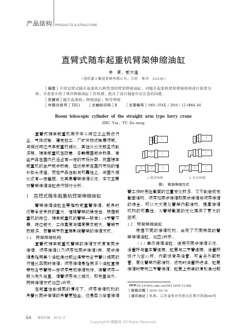
1.1 臂架伸缩机构直臂式随车起重机臂架的伸缩方式常有同步伸缩、顺序伸缩以及顺序加同步伸缩3种。
同步伸缩是指用单个油缸通过钢丝绳带动各节臂以相同的行程比率同时伸缩;顺序伸缩是指用多个油缸直接带动各节臂按一定顺序完成伸缩动作,伸臂顺序一般为先外后里,缩臂顺序与之相反,即先里后外。
两种伸缩方式如图1所示。
在起重性能相同的情况下,顺序伸缩机构的吊臂比同步伸缩的吊臂更轻些,这是因为后者伸缩臂工作时危险截面的位置变化较多,又不能做成变截面结构。
顺序加同步伸缩即同步伸缩与顺序伸缩的综合,可以大大简化臂架内部结构,提高伸缩机构的可靠性,为臂架截面的优化提供了更大的空间。
typec 方案

typec 方案Type-C方案Type-C接口是一种全球统一标准的连接方式,通过使用Type-C接口,可以实现数据传输、充电和视频输出等功能。
本文将介绍Type-C 的起源、特点以及应用领域。
一、Type-C的起源Type-C接口最早由USB 3.0 Promoter Group在2014年提出,并由USB-IF(USB实现者论坛)负责标准的制定和推广。
它是随着技术的发展和人们对连接器的需求提出的一种新型连接方案,在取代传统USB接口方面具有重要意义。
二、Type-C的特点1. 可逆性:Type-C接口采用了对称设计,插头方向无需顾忌,可以插入任何一面,大大方便了使用者。
2. 支持高速传输:Type-C接口支持USB3.1标准,传输速度可达到10Gbps,比传统USB接口快数倍。
3. 支持高功率充电:Type-C接口支持高达100W的功率传输,可以实现快速充电,节省充电时间。
4. 多功能性:Type-C接口不仅支持数据传输和充电,还可以支持视频输出、音频传输等多种功能,为用户提供更加便利的连接体验。
三、Type-C的应用领域1. 电子设备:Type-C接口已广泛应用于手机、平板电脑、笔记本电脑等移动设备中,取代了传统的Micro USB接口,为用户提供更加便捷的充电和数据传输方案。
2. 台式机设备:Type-C接口也逐渐应用到台式机设备中,可以实现数据传输、充电和显示输出等功能,简化了设备之间的连接。
3. 外设设备:越来越多的外设设备,如鼠标、键盘、摄像头等,开始使用Type-C接口进行连接,提高了连接的稳定性和速度。
4. 车载设备:Type-C接口在车载设备中的应用也愈发普及,用于连接充电器、音响系统等设备,提供更多的连接选项。
总结:Type-C接口作为一种新的全球统一标准连接方案,具有可逆性、高速传输、高功率充电和多功能性的特点,被广泛应用于各类电子设备、台式机设备、外设设备以及车载设备中。
新型并沟线夹的设计及其在配网线路中的应用

《宁夏电力》2015年第3期收稿日期:2015-03-20作者简介:韩世军(1983),男,工学硕士,从事电工理论与新技术研究工作。
新型并沟线夹的设计及其在配网线路中的应用韩世军1,毛吉贵1,朱菊2,秦力1,车超3,王鹏珍3(1.国网吴忠供电公司,宁夏吴忠751100;2.神华宁煤集团烯烃公司,宁夏银川750011;3.宁夏大学电气工程与自动化系,宁夏银川750021)摘要:针对配网主干线与用户引流线截面差别较大而导致接续点严重发热的问题,深入分析了接触电阻增大的原因,设计出一种全包裹结构全压接形式的新型并沟线夹,并在配网线路中应用。
应用结果表明:新型并沟线夹具有良好的电气特性,解决了不同截面导线的接续问题,为电力行业解决异径导线接续问题提供了新的途径。
关键词:配电网;接续金具;并沟线夹;接触电阻中图分类号:TM 726文献标志码:A文章编号:1672-3643(2015)03-0027-03有效访问地址:http :///10.3969/j.issn.1672-3643.2015.03.006Design of new type parallel groove clamp and the application in transmission line ofdistribution networkHAN Shijun 1,MAO Jigui 1,ZHU Ju 2,QIN Li1,CHE Chao 3,WANG Pengzhen 3(1.Wuzhong Power Supply Filiale of State Grid Ningxia Power Co.,Wuzhong Ningxia 751100,China ;2.Alkene Company of Shenhua Ningxia Coal Industry Group ,Yinchuan Ningxia 750011,China ;3.School of Electrical Engineering &Automation ,Ningxia University ,Yinchuan Ningxia 750021,China )Abstract :Aiming at the problem of a greater difference of section in main line and user download line caused the connection point serious heat ,deeply analyzes the cause of contact resistance increase ,designs a new type parallel groove clamp with full packaged structure and whole pressing contact form ,and applies in distribution line.The application result shows that new type parallel groove clamp has better electrical characteristic ,solves the problem of different section conductors toconnect ,provides a new way for solving the different section conductors connection problem ofpower sector.Key words :distribution network ;connection fitting ;parallel groove clamp ;contact resistance 阅韵陨:10.3969/j.issn.1672-3643.2015.03.00627··2011年5月14日10时05分,吴忠供电公司北郊变电站515仪表线过流I段保护动作,开关跳闸,重合不成功。
CR2016 Specification

CR2016
TECHNICAL SPECIFICATION FOR LITHIUM MANGANESE DIOXIDE BUTTON CELL
DATE:20/3/2010 SPEC.NO.:TL-CR2016 REVISION:2010M
TELONG ENERGY TECHNOLOGY CO., LTD.
(4) Service life after storage at high temperature: Service life of batteries when tested in accordance with Subparagraph 4.4(6) shall meet the requirements set forth in Table 3 [ TABLE 3 ] TEST ITEM STORAGE TEMP. STORAGE PERIOD REQUIREMENT RE1 Temperature and humidity: Unless otherwise specified elsewhere, tests shall be conducted at ordinary temperature (20±2℃) and ordinary humidity (65±5%RH). Α 4.2 Storage of test specimen batteries: Specimen batteries to be tested shall be kept at the ambient temperature of 25℃ or below and at the relative humidity of 75% or below. Α 4.3 Measuring instruments and devices: Outer micrometers specified inJJG26-95, dial gauges specified in JIS B 7503,
TD信息元素详解
信息元素功能性定义作者:李欣目录目录 (1)信息元素功能性定义 (11)1 核心网信息元素 (11)1.1 CN Information elements (11)1.2 CN Domain System Information (11)1.3 CN Information info (11)1.4 IMEI (11)1.5 IMSI (GSM-MAP) (11)1.6 Intra Domain NAS Node Selector (11)1.7 Location Area Identification (12)1.8 NAS message (12)1.9 NAS system information (GSM-MAP) (12)1.10 Paging record type identifier (12)1.11 PLMN identity (12)1.12 PLMN Type (12)1.13 P-TMSI (GSM-MAP) (12)1.14 RAB identity (12)1.15 Routing Area Code (12)1.16 Routing Area Identification (13)1.17 TMSI (GSM-MAP) (13)2 UTRAN 移动信息元素 (13)2.1 Cell Access Restriction (13)2.2 Cell identity (13)2.3 Cell selection and re-selection info for SIB3/4 (13)2.4 Cell selection and re-selection info for SIB11/12 (13)2.5 Mapping Info (14)2.6 URA identity (14)3 UE 信息元素 (14)3.1 Activation time (14)3.2 Capability Update Requirement (14)3.3 Cell update cause (15)3.4 Ciphering Algorithm (15)3.5 Ciphering mode info (15)3.6 CN domain specific DRX cycle length coefficient (15)3.7 CPCH Parameters (15)3.8 C-RNTI (15)3.9 DRAC system information (15)3.10 Void (16)3.11 Establishment cause (16)3.12 Expiration Time Factor (16)3.13 Failure cause (16)3.14 Failure cause and error information (16)3.15 Initial UE identity (16)3.16 Integrity check info (16)3.17 Integrity protection activation info (17)3.18 Integrity protection Algorithm (17)3.19 Integrity protection mode info (17)3.20 Maximum bit rate (17)3.21 Measurement capability (17)3.22 Paging cause (17)3.23 Paging record (17)3.24 PDCP capability (17)3.25 Physical channel capability (18)3.26 Protocol error cause (18)3.27 Protocol error indicator (18)3.28 RB timer indicator (18)3.29 Redirection info (18)3.30 Re-establishment timer (18)3.31 Rejection cause (18)3.32 Release cause (18)3.33 RF capability FDD (19)3.34 RLC capability (19)3.35 RLC re-establish indicator (19)3.36 RRC transaction identifier (19)3.37 Security capability (19)3.38 START (19)3.39 Transmission probability (19)3.40 Transport channel capability (20)3.41 UE multi-mode/multi-RAT capability (20)3.42 UE radio access capability (20)3.43 UE Timers and Constants in connected mode (21)3.44 UE Timers and Constants in idle mode (21)3.45 UE positioning capability (21)3.46 URA update cause (21)3.47 U-RNTI (21)3.48 U-RNTI Short (21)3.49 UTRAN DRX cycle length coefficient (21)3.50 Wait time (21)3.51 UE Specific Behavior Information 1 idle (21)3.52 UE Specific Behavior Information 1 interRAT (22)4 无线承载信息元素 (22)4.0 Default configuration identity (22)4.1 Downlink RLC STATUS info (22)4.2 PDCP info (22)4.3 PDCP SN info (22)4.4 Polling info (22)4.5 Predefined configuration identity (23)4.6 Predefined configuration value tag (23)4.7 Predefined RB configuration (23)4.8 RAB info (23)4.9 RAB info Post (23)4.10 RAB information for setup (23)4.11 RAB information to reconfigure (24)4.12 NAS Synchronization indicator (24)4.13 RB activation time info (24)4.14 RB COUNT-C MSB information (24)4.15 RB COUNT-C information (24)4.16 RB identity (24)4.17 RB information to be affected (24)4.18 RB information to reconfigure (25)4.19 RB information to release (25)4.20 RB information to setup (25)4.21 RB mapping info (25)4.22 RB with PDCP information (25)4.23 RLC info (25)4.24 Signaling RB information to setup (26)4.25 Transmission RLC Discard (26)5 传输信道信息元素 (26)5.1 Added or Reconfigured DL TrCH information (26)5.2 Added or Reconfigured UL TrCH information (27)5.3 CPCH set ID (27)5.4 Deleted DL TrCH information (27)5.5 Deleted UL TrCH information (27)5.6 DL Transport channel information common for all transport channels (27)5.7 DRAC Static Information (27)5.8 Power Offset Information (28)5.9 Predefined TrCH configuration (28)5.10 Quality Target (28)5.11 Semi-static Transport Format Information (28)5.12 TFCI Field 2 Information (28)5.13 TFCS Explicit Configuration (28)5.14 TFCS Information for DSCH (TFCI range method) (29)5.15 TFCS Reconfiguration/Addition Information (29)5.16 TFCS Removal Information (29)5.17 Void (29)5.18 Transport channel identity (29)5.19 Transport Format Combination (TFC) (29)5.20 Transport Format Combination Set (29)5.21 Transport Format Combination Set Identity (29)5.22 Transport Format Combination Subset (29)5.23 Transport Format Set (29)5.24 UL Transport channel information common for all transport channels (30)6 物理信道信息元素 (30)6.1 AC-to-ASC mapping (30)6.2 AICH Info (30)6.3 AICH Power offset (30)6.4 Allocation period info (30)6.5 Alpha (30)6.6 ASC Setting (30)6.7 Void (31)6.8 CCTrCH power control info (31)6.9 Cell parameters Id (31)6.10 Common timeslot info (31)6.11 Constant value (31)6.12 CPCH persistence levels (31)6.13 CPCH set info (31)6.14 CPCH Status Indication mode (31)6.15 CSICH Power offset (32)6.16 Default DPCH Offset Value (32)6.17 Downlink channelisation codes (32)6.18 Downlink DPCH info common for all RL (32)6.19 Downlink DPCH info common for all RL Post (32)6.20 Downlink DPCH info common for all RL Pre (32)6.21 Downlink DPCH info for each RL (32)6.22 Downlink DPCH info for each RL Post (33)6.23 Downlink DPCH power control information (33)6.24 Downlink information common for all radio links (33)6.25 Downlink information common for all radio links Post (33)6.26 Downlink information common for all radio links Pre (33)6.27 Downlink information for each radio link (33)6.28 Downlink information for each radio link Post (33)6.29 Void (33)6.30 Downlink PDSCH information (33)6.31 Downlink rate matching restriction information (34)6.32 Downlink Timeslots and Codes (34)6.33 DPCH compressed mode info (34)6.34 DPCH Compressed Mode Status Info (34)6.35 Dynamic persistence level (34)6.36 Frequency info (34)6.37 Individual timeslot info (35)6.38 Individual Timeslot interference (35)6.39 Maximum allowed UL TX power (35)6.40 Void (35)6.41 Midamble shift and burst type (35)6.42 PDSCH Capacity Allocation info (35)6.43 PDSCH code mapping (36)6.44 PDSCH info (36)6.45 PDSCH Power Control info (36)6.46 PDSCH system information (36)6.47 PDSCH with SHO DCH Info (36)6.48 Persistence scaling factors (36)6.49 PICH Info (36)6.50 PICH Power offset (37)6.51 PRACH Channelisation Code List (37)6.52 PRACH info (for RACH) (37)6.53 PRACH partitioning (37)6.54 PRACH power offset (37)6.55 PRACH system information list (37)6.56 Predefined PhyCH configuration (38)6.57 Primary CCPCH info (38)6.58 Primary CCPCH info post (38)6.59 Primary CCPCH TX Power (38)6.60 Primary CPICH info (38)6.61 Primary CPICH Tx power (38)6.62 Primary CPICH usage for channel estimation (38)6.63 PUSCH info (38)6.64 PUSCH Capacity Allocation info (38)6.65 PUSCH power control info (39)6.66 PUSCH system information (39)6.67 RACH transmission parameters (39)6.68 Radio link addition information (39)6.69 Radio link removal information (39)6.70 SCCPCH Information for FACH (39)6.71 Secondary CCPCH info (39)6.72 Secondary CCPCH system information (40)6.73 Secondary CPICH info (40)6.74 Secondary scrambling code (40)6.75 SFN Time info (40)6.76 SSDT cell identity (40)6.77 SSDT information (40)6.78 STTD indicator (40)6.79 TDD open loop power control (41)6.80 TFC Control duration (41)6.81 TFCI Combining Indicator (41)6.82 TGPSI (41)6.83 Time info (41)6.84 Timeslot number (41)6.85 TPC combination index (41)6.86 TSTD indicator (41)6.87 TX Diversity Mode (41)6.88 Uplink DPCH info (41)6.89 Uplink DPCH info Post (42)6.90 Uplink DPCH info Pre (42)6.91 Uplink DPCH power control info (42)6.92 Uplink DPCH power control info Post (42)6.93 Uplink DPCH power control info Pre (42)6.94 Uplink Timeslots and Codes (42)6.95 Uplink Timing Advance (42)6.96 Uplink Timing Advance Control (43)7 测量信息元素 (43)7.1 Additional measurements list (43)7.2 Cell info (43)7.3 Cell measured results (43)7.4 Cell measurement event results (44)7.5 Cell reporting quantities (44)7.6 Cell synchronization information (44)7.7 Event results (44)7.8 FACH measurement occasion info (45)7.9 Filter coefficient (45)7.10 HCS Cell re-selection information (45)7.11 HCS neighboring cell information (45)7.12 HCS Serving cell information (45)7.13 Inter-frequency cell info list (46)7.14 Inter-frequency event identity (46)7.15 Inter-frequency measured results list (46)7.16 Inter-frequency measurement (46)7.17 Inter-frequency measurement event results (47)7.18 Inter-frequency measurement quantity (47)7.19 Inter-frequency measurement reporting criteria (47)7.20 Inter-frequency measurement system information (47)7.21 Inter-frequency reporting quantity (47)7.22 Inter-frequency SET UPDATE (48)7.23 Inter-RAT cell info list (48)7.24 Inter-RAT event identity (48)7.25 Inter-RAT info (48)7.26 Inter-RAT measured results list (48)7.27 Inter-RAT measurement (49)7.28 Inter-RAT measurement event results (49)7.29 Inter-RAT measurement quantity (49)7.30 Inter-RAT measurement reporting criteria (49)7.31 Inter-RAT measurement system information (50)7.32 Inter-RAT reporting quantity (50)7.33 Intra-frequency cell info list (50)7.34 Intra-frequency event identity (50)7.35 Intra-frequency measured results list (50)7.36 Intra-frequency measurement (50)7.37 Intra-frequency measurement event results (51)7.38 Intra-frequency measurement quantity (51)7.39 Intra-frequency measurement reporting criteria (51)7.40 Intra-frequency measurement system information (51)7.41 Intra-frequency reporting quantity (52)7.42 Intra-frequency reporting quantity for RACH reporting (52)7.43 Maximum number of reported cells on RACH (52)7.44 Measured results (52)7.45 Measured results on RACH (52)7.46 Measurement Command (52)7.47 Measurement control system information (53)7.48 Measurement Identity (53)7.49 Measurement reporting mode (53)7.50 Measurement Type (53)7.51 Measurement validity (53)7.52 Observed time difference to GSM cell (53)7.53 Periodical reporting criteria (53)7.54 Primary CCPCH RSCP info (54)7.55 Quality measured results list (54)7.56 Quality measurement (54)7.57 Quality measurement event results (54)7.58 Quality measurement reporting criteria (54)7.59 Quality reporting quantity (54)7.60 Reference time difference to cell (54)7.61 Reporting Cell Status (55)7.62 Reporting information for state CELL_DCH (55)7.63 SFN-SFN observed time difference (55)7.64 Time to trigger (55)7.65 Timeslot ISCP info (55)7.66 Traffic volume event identity (55)7.67 Traffic volume measured results list (55)7.68 Traffic volume measurement (55)7.69 Traffic volume measurement event results (56)7.70 Traffic volume measurement object (56)7.71 Traffic volume measurement quantity (56)7.72 Traffic volume measurement reporting criteria (56)7.73 Traffic volume measurement system information (56)7.74 Traffic volume reporting quantity (56)7.75 UE internal event identity (56)7.76 UE internal measured results (57)7.77 UE internal measurement (57)7.78 UE internal measurement event results (57)7.79 UE internal measurement quantity (57)7.80 UE internal measurement reporting criteria (57)7.81 Void (58)7.82 UE Internal reporting quantity (58)7.83 UE Rx-Tx time difference type 1 (58)7.84 UE Rx-Tx time difference type 2 (58)7.85 UE Transmitted Power info (58)7.86 UE positioning Ciphering info (58)7.87 UE positioning Error (58)7.88 UE positioning GPS acquisition assistance (59)7.89 UE positioning GPS almanac (59)7.90 UE positioning GPS assistance data (59)7.91 UE positioning GPS DGPS corrections (59)7.92 UE positioning GPS ionospheric model (59)7.93 UE positioning GPS measured results (59)7.94 UE positioning GPS navigation model (60)7.95 UE positioning GPS real-time integrity (60)7.96 UE positioning GPS reference time (60)7.97 UE positioning GPS UTC model (61)7.98 UE positioning IPDL parameters (61)7.99 UE positioning measured results (61)7.100 UE positioning measurement (61)7.101 UE positioning measurement event results (61)7.102 Void (62)7.103 UE positioning OTDOA assistance data for UE-assisted (62)7.104 Void (62)7.105 UE positioning OTDOA measured results (62)7.106 UE positioning OTDOA neighbor cell info (62)7.107 UE positioning OTDOA quality (63)7.108 UE positioning OTDOA reference cell info (63)7.109 UE positioning position estimate info (64)7.110 UE positioning reporting criteria (64)7.111 UE positioning reporting quantity (64)7.112 T ADV info (65)8 其它信息元素 (65)8.1 BCCH modification info (65)8.2 BSIC (65)8.3 CBS DRX Level 1 information (65)8.4 Cell Value tag (65)8.5 Inter-RAT change failure (65)8.6 Inter-RAT handover failure (66)8.7 Inter-RAT UE radio access capability (66)8.8 Void (66)8.9 MIB Value tag (66)8.10 PLMN Value tag (66)8.11 Predefined configuration identity and value tag (66)8.12 Protocol error information (66)8.13 References to other system information blocks (66)8.14 References to other system information blocks and scheduling blocks (67)8.15 Rplmn information (67)8.16 Scheduling information (67)8.17 SEG COUNT (67)8.18 Segment index (67)8.19 SIB data fixed (67)8.20 SIB data variable (67)8.21 SIB type (67)8.22 SIB type SIBs only (67)9 ANSI-41 Information elements (68)10 Multiplicity values and type constraint values (68)信息元素功能性定义消息是由多个信息元素组合而成,信息元素根据其功能的不同划分为:核心网域信息元素、UTRAN 移动信息元素、UE 信息元素、无线承载信息元素、传输信道信息元素、物理信道信息元素和测量信息元素。
《TYPEC介绍》课件

TYPEC的标准
1
USB Type-C标准
USB Type-C成为TYPEC接口的标准之一,
USB Power Delivery标准
2
实现了更快速的数据传输和充电能力。
USB Power Delivery标准使TYPEC接口支持
更高功率的充电,提供更快速的充电体
验。
3
Thunderbolt 3标准
TYPEC的优势
1 数据传输速度
2 充电速度
TYPEC接口支持高速数据传输,大大提高了文 件传输效率。
TYPEC接口的快速充电功能,可以让设备在短 时间内获得更多电量。
3 端口统一
4 兼容性强
TYPEC接口实现了不同设备之间的标准化连接, 简化了使用过程。
TYPEC接口与其他接口兼容性强,可以连接各 应用领域
智能手机
现代智能手机普遍采用TYPEC接口,提供更快速、 稳定的充电和数据传输。
笔记本电脑
TYPEC接口在笔记本电脑中的应用越来越普遍, 方便连接外部设备。
平板电脑
TYPEC接口的高速充电和数据传输能力,使平板 电脑更加便捷和高效。
其他设备
除了以上设备,TYPEC接口还广泛应用于其他消 费电子产品,如音频设备、相机等。
技术创新
随着技术的不断进步,TYPEC接 口将会融入更多设备,并拥有更 多功能和应用。
市场前景
TYPEC接口市场规模不断扩大, 预计未来几年将会取得更大的增 长和普及。
结论
在今天的课程中,我们介绍了TYPEC接口的概念、优势和应用领域,并了解了TYPEC接口的标准、问题和解决方 案。此外,我们还展望了TYPEC的未来发展趋势。
《TYPEC介绍》PPT课件
高精度热成像与光学双谱网络小型定位系统说明书

HM-TD5567T-7/WThermographic Thermal & Optical Bi-spectrum Network MINI Positioning SystemHIKMICRO HM-TD5567T-7/W Thermographic Thermal & Optical Bi-spectrum Network MINI Positioning System equipped with built-in GPU which supports intelligent behavior analysis algorithm, can realize high-precision VCA detection and real-time alarm. It is applied to fire-prevention pu5rposes in scenes such as transformer substation, recycling center, gas station, and factory. The pre-alarm system helps you discover unexpected events immediately and protects your property.Key Feature●Behavior analysis function, based on deep learning algorithm: line crossing, intrusion, region entrance & exit●Temperature exception alarm for fire prevention●Fire detection algorithm●640 × 512 resolution 17 μm, VOx UFPA, NETD ≤ 35 mK (25°C, F# = 1.0)●Image processing technology: Liner, histogram, and self-adaptive thermal AGC mode, DDE, 3D DNR●High quality detector with 10 years guaranteeSpecificationThermal ModuleImage Sensor Vanadium Oxide Uncooled Focal Plane ArraysResolution 640 × 512Pixel Pitch 17 μmSpectral Range 8 μm to 14 μmNETD ≤ 35 mK (25°C, F# = 1.0)Focal Length 6.3 mmIFOV 2.7 mradAperture F1.0Field of View 88.5° × 73.2° (H × V)Min. Focusing Distance 0.6 mDigital Zoom × 2, × 4, × 8Optical ModuleImage Sensor 1/2.8" Progressive Scan CMOSResolution 2688 × 1520, 4 MPMin. Illumination Color: 0.05 Lux @ (F1.6, AGC ON), B/W: 0.01 Lux @ (F1.6, AGC ON)Field of View 58.4° × 33.8° (H × V) to 2.14° × 1.2° (H × V)Focal Length 4.8 mm to 153 mm, 32 ×Aperture (Range) F1.2 to F4.4Focus Mode Semi-auto, manualDigital Zoom × 2, × 4, × 8, × 16Shutter Speed 1 s to 1/100,000 sWDR 120 dBOptical Defog YesImage EffectPicture in Picture Display partial image of thermal channel on the full screen of optical channel Target Coloration Yes. Supported in white hot and black hot mode.PTZMovement Range Pan: 360° Continuous Rotate; Tilt: From -90° to +90° (auto flip)Pan Speed Configurable, From 0.5°/s to 90°/sTilt Speed Configurable, From 0.5°/s to 40°/sProportional Zoom YesPresets 300Patrol Scan 8 patrols; Up to 32 presets per patrolPower Off Memory YesPark Preset/Patrol Scan/Auto Scan/Tilt Scan/Random Scan/Frame Scan/Panorama Scan PT Status Turn On/Turn OffScheduled Task Preset/Patrol Scan/Auto Scan/Tilt Scan/Random Scan/Frame Scan/Panorama Scan/Dome Reboot/Dome Adjust/Aux OutputIlluminatorIR Distance Up to 30 mIR Intensity and Angle Automatically adjustedSmart FunctionVCA 4 VCA rule types (line crossing, intrusion, region entrance, and region exiting), 10 scenes and 8 VCA rules for each scene.Temperature Measurement 3 temperature measurement rule types, 273 presets as scene, 21 rules of each scene (10 points, 10 areas, and 1 line)Temperature Range -20°C to 550°C (-4°F to 1022°F) Temperature Accuracy Max (± 2°C, ± 2%)Fire Detection Dynamic fire and smoke detection, up to 10 fire points and 10 smoke points detectable.Video and AudioMain Stream Optical channel50 Hz: 25 fps (2688 × 1520, 1920 × 1080, 1280 × 960, 1280 × 720)60 Hz: 30 fps (2688 × 1520, 1920 × 1080, 1280 × 960, 1280 × 720)Thermal channel50 fps (1920 × 1080, 1280 × 960, 1280 × 720, 704 × 576, 640 × 512, 384 × 288)Sub-stream Optical channel50 Hz: 25fps (704 × 576, 352 × 288)60 Hz: 30 fps (704 × 576, 352 × 288) Thermal channel50 fps (704 × 576, 640 × 512, 384 × 288)Video Compression Main stream: H.265+/H.265/H.264+/ H.264 Sub-stream: H.265/H.264/MJPEGAudio Compression G.711alaw/G.711ulaw/G.722.1/G.726/MP2L2/AAC/PCM NetworkProtocols IPv4/IPv6, HTTP, HTTPS, 802.1x, Qos, FTP, SMTP, UPnP, SNMP, DNS, DDNS, NTP, RTSP, RTCP, RTP, TCP, UDP, IGMP, ICMP, DHCP, PPPoENetwork Storage MicroSD/SDHC/SDXC card (up to 128 GB) local storage, and NAS (NFS, SMB/CIFS), auto network replenishment (ANR)API ISAPI, HIKVISION SDK, third-party management platform, ONVIF (Profile S, Profile G, Profile T)Simultaneous Live View Up to 20 channelsUser/Host level Up to 32 users. 3 levels: administrator, operator, userSecurity User authentication (ID and Password), MAC address binding, HTTPS encryption, IEEE 802.1x (EAP-MD5, EAP-TLS), access control, IP address filteringClient iVMS-4200, Hik-ConnectWeb Browser Live view (plug-in allowed): Internet Explorer 11 Live view (plug-in free): Chrome 57.0 +, Firefox 52.0 + Local service: Chrome 57.0 +, Firefox 52.0 +InterfaceAlarm Input 2-ch inputs (0 to 5 VDC)Alarm Output 2-ch relay outputs, alarm response actions configurableAlarm Action Preset/patrol scan/SD card record/relay output/smart capture/FTP upload/email linkageAudio Input 1 Audio Output 1Communication Interface 1, RJ45 10 M/100 M self-adaptive Ethernet interface. 1, RS-485 interfaceGeneralMenu Language 32 languagesEnglish, Russian, Estonian, Bulgarian, Hungarian, Greek, German, Italian, Czech, Slovak, French, Polish, Dutch, Portuguese, Spanish, Romanian, Danish, Swedish, Norwegian, Finnish, Croatian, Slovenian, Serbian, Turkish, Korean, Traditional Chinese, Thai, Vietnamese, Japanese, Latvian, Lithuanian, Portuguese (Brazil)Power Supply 24 VDC Power Consumption 20 WWorking Temperature/Humidity -40°C to 70°C (-40°F to 158°F) 90% or lessWiper YesProtection Level IP67 StandardTVS 6000V lightning protection, surge protection, voltage transient protectionDimensions 321 mm × 194 mm × 153 mm (12.64" × 7.64" × 6.02") Weight Approx. 4.8 kg (10.582 lb)DRI Range Table* The table is only for reference and the performance may vary according to different environment.* The optimal detection, recognition, and identification distances are calculated according to Johnson’s Criteria.Detection Range: In order to distinguish an object from the background, the object must be covered by 1.5 or more pixels. Recognition Range: In order to classify the object (animal, human, vehicle, etc.), the object must be covered by 6 or more pixels.Identification Range: In order to identify the object and describe it in details, the object must be covered by 12 or more pixels..Detection Range (Vehicles: 1.4 × 4.0 m) Detection Range (Humans: 1.8 × 0.5 m) Recognition Range (Vehicles: 1.4 × 4.0 m) Recognition Range (Humans: 1.8 × 0.5 m) Identification Range (Vehicles: 1.4 × 4.0 m) Identification Range (Humans: 1.8 × 0.5 m) 568 m185 m142 m46 m71 m23 mSmart Function Table* The table is only for reference and the performance may vary according to different environment.VCA Range(Vehicles: 1.4 × 4.0 m) VCA Range (Humans: 1.8 × 0.5 m) Temperature Measurement (Object: 2 × 2 m) Temperature Measurement (Object: 1 × 1 m) Fire Detection (Object: 2 × 2 m) Fire Detection (Object: 1 × 1 m) 132 m44 m 148 m 74 m371 m185 mAvailable Model HM-TD5567T-7/WDimensionCOMPLIANCE NOTICE: The thermal series products might be subject to export controls in various countries or regions, including without limitation, the United States, European Union, United Kingdom and/or other member countries of the Wassenaar Arrangement. Please consult your professional legal or compliance expert or local government authorities for any necessary export license requirements if you intend to transfer, export, re-export the thermal series products between different countries.。
睿思科技发布新一代USBType-C^TM与USB Power DeIivery3.0解决方案

率 晶体管的业 界顶级性能与罗姆 的 GaN功率器件 下 一 代 用 于 高规 USB Type—C传输 线 的 USB PD3.0
技术优势及 丰富的 电子元器件 设计 /制造综合 实 E—Marker ID控 制 芯 片 ,FLT1 l2—— 提 供 USB PD3.0
力 。双方 将利 用 GaN Systems公 司 的 GaNPXTM 封装 PPS与 QC4.0规 格 的 PD控制 芯 片 ,以满 足笔 记 本
与 发展 ,开 始就 GaN功 率器件 事 业展 开合 作 。
USB Power Delivery3.0产 品 ,其 中包 括 FL55OO— —
此 次合 作将 充 分发 挥 GaN Systems公 司 GaN功 USB3.1 Gen2 (1OGbps)Hub控制 芯 片 ,FL703l— —
Reflexion ̄ LK Prime CMP平 台 上 的 平 坦 化 技 术 、 这 种 能力 的用例 有 :当 wi—Fi无 线 电专用 于手 机投 PROVisionTM平台上的电子束检测技术 。凭借这项 影 时 ,另 一个 流 式视 频 将用 于汽 车 的移 动或 附属设
经过 验 证 的集 成 材料 解 决 方案 ,客 户可 以缩 短 其 产 品 投放 市 场 的时 问 ,并 提 高 7nm 工 艺 及 以下 的芯 片性 能 。 (来 自应用 材 料公 司 )
睿思科技发布新 一代 USB Type-CTM与 USB Power De Ii very 3.0解 决 方 案
日前 ,GaN Systems公 司 (GaN Systems Inc.)和
罗姆 (ROHM Co.,Ltd.)为 促进 电力 电子市 场 的创新
近 日,睿 思科 技 发布 了新 一 代 USB Type—cTM与
赛米控丹佛斯 SEMITRANS IGBT模块 SKM75GB17E4 数据表
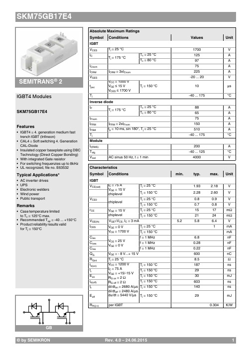
®2IGBT4 ModulesSKM75GB17E4Features•IGBT4 = 4. generation medium fast trench IGBT (Infineon)•CAL4 = Soft switching 4. Generation CAL-Diode•Insulated copper baseplate using DBC Technology (Direct Copper Bonding) •With integrated Gate resistor•For switching frequenzies up to 8kHz •UL recognized, file no. E63532Typical Applications*•AC inverter drives •UPS•Electronic welders •Wind power •Public transportRemarks•Case temperature limited to T c = 125°C max.•Recommended T op = -40 ... +150°C •Product reliability results valid for T j = 150°CAbsolute Maximum Ratings SymbolConditions Values UnitIGBT V CES T j =25°C 1700V I C T j =175°CT c =25°C 125A T c =80°C97A I Cnom 75A I CRMI CRM = 3xI Cnom 225A V GES -20...20V t psc V CC =1000V V GE ≤ 15V V CES ≤ 1700VT j =150°C10µs T j-40 (175)°C Inverse diode I F T j =175°CT c =25°C 88A T c =80°C 65A I Fnom75A I FRM I FRM = 2xI Fnom150A I FSM t p =10ms, sin 180°, T j =25°C510A T j -40...175°C Module I t(RMS)200A T stg -40 (125)°C V isolAC sinus 50 Hz, t =1min4000VCharacteristics SymbolConditions min.typ.max.UnitIGBT V CE(sat)I C =75A V GE =15V chiplevel T j =25°C 1.93 2.18V T j =150°C 2.28 2.60V V CE0chiplevel T j =25°C 0.80.9V T j =150°C 0.70.8V r CE V GE =15V chiplevelT j =25°C 1517m ΩT j =150°C2124m ΩV GE(th)V GE =V CE , I C =3mA 5.25.86.4V I CES V GE =0V V CE =1700V T j =25°C 1mA T j =150°C mA C ies V CE =25V V GE =0Vf =1MHz 6.8nF C oes f =1MHz 0.28nF C res f =1MHz0.22nF Q G V GE =- 8 V...+ 15 V 600nC R Gint T j =25°C 8.5Ωt d(on)V CC =1200V I C =75AV GE =+15/-15V R G on =2ΩR G off =2Ωdi/dt on =2680A/µs di/dt off =2480A/µs du/dt =5440V/µs T j =150°C 187ns t r T j =150°C 29ns E on T j =150°C 30mJ t d(off)T j =150°C 603ns t f T j =150°C 140ns E off T j =150°C 29mJ R th(j-c)per IGBT0.304K/WCharacteristics SymbolConditionsmin.typ.max.UnitInverse diodeV F = V EC I F =75AV GE =0V chiplevelT j =25°C 2.00 2.40V T j =150°C 2.14 2.56V V F0chiplevel T j =25°C 1.32 1.56V T j =150°C 1.08 1.22V r FchiplevelT j =25°C 9.111m ΩT j =150°C1418m ΩI RRM I F =75A di/dt off =2860A/µs V GE =-15VV CC =1200VT j =150°C 95A Q rr T j=150°C27µC E rr T j =150°C 21mJR th(j-c)per diode0.632K/W Module L CE 30nH R CC'+EE'terminal-chip T C =25°C 0.65m ΩT C =125°C1.09m ΩR th(c-s)per module 0.040.05K/W M s to heat sink M635Nm M t to terminals M52.55Nm Nm w160g® 2IGBT4 ModulesSKM75GB17E4Features•IGBT4 = 4. generation medium fast trench IGBT (Infineon)•CAL4 = Soft switching 4. Generation CAL-Diode•Insulated copper baseplate using DBC Technology (Direct Copper Bonding) •With integrated Gate resistor•For switching frequenzies up to 8kHz •UL recognized, file no. E63532Typical Applications*•AC inverter drives •UPS•Electronic welders •Wind power •Public transportRemarks•Case temperature limited to T c = 125°C max.•Recommended T op = -40 ... +150°C •Product reliability results valid for T j = 150°CThis is an electrostatic discharge sensitive device (ESDS), international standard IEC 60747-1, Chapter IX* The specifications of our components may not be considered as an assurance of component characteristics. Components have to be tested for the respective application. Adjustments may be necessary. The use of SEMIKRON products in life support appliances and systems is subject to prior specification and written approval by SEMIKRON. We therefore strongly recommend prior consultation of our staff.。
制浆造纸第三代真空系统技术—芬兰兰泰克Ecopump 变速透平机

简单说来,造纸就是一个脱水过程,因为从纸浆到最终的纸或纸板,含水量从99%减少到约10%。
真空系统在造纸脱水中扮演着重要角色,如排水、纸幅处理、毛布洗涤等。
正因如此,真空的产生和供给在纸浆、纸和纸板生产中都非常关键。
纸机上与真空相关的设备,如吸水箱、抽吸辊等,均需要不同的真空度和流量。
另外,同一台纸机在所生产的纸张定量或是纸机织物类型、使用天数等工艺状况发生变化时,真空度和抽气量都会随之发生变化。
一台现代化的纸机,抽真空所需电耗占整台纸机全部电耗的15%~30%。
一个高效的纸机真空系统需要达到以下要求:● 能够适应生产状况的变化;● 能够灵活工作,并能随时达到供需平衡;制浆造纸第三代真空系统技术—芬兰兰泰克Ecopump变速透平机2016年4月19-21日,“中芬纸机真空系统节能与优化论坛”在江苏常熟理文铂尔曼酒店及上海国际会议中心成功举办。
芬兰兰泰克系统有限公司CEO Jukka Lehto先生和中国总裁杨凤辉先生在论坛上介绍了Ecopump真空系统节能与优化技术的优势和成功案例。
Ecopump变速透平机技术可比水环泵和定速透平机技术节能30%~70%,与水环泵相比无需水环。
纸机真空系统发展历程new Products/technology新产品 新技术54NO.5 2016CHINA PAPER NEWSLETTERS . All Rights Reserved.new Products/technology新产品 新技术●低故障,可信赖,改造及维护停机时间尽可能短纸机真空系统技术发展历程(1)纸机第一代真空系统技术——水环泵技术水环泵技术发明于120多年前,现在全球仍有90%以上的纸机使用该技术。
(2)纸机第二代真空系统技术——透平机技术透平机技术发明于20世纪40年代,与水环泵技术相比,透平机技术汽水分离充分,无需水环,抽真空效率要高20%~30%。
依据抽真空级数,市场上的第二代真空系统技术又可分为单级透平机和多级透平机。
Omron E3F2 线性光电传感器说明书
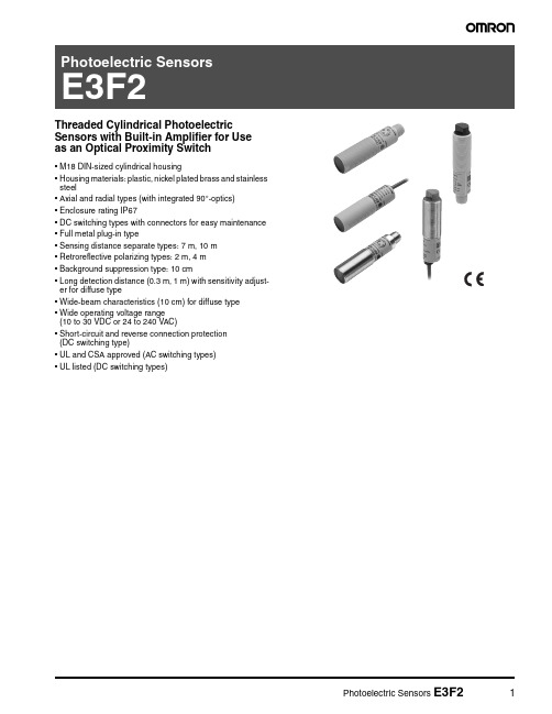
Threaded Cylindrical PhotoelectricSensors with Built-in Amplifier for Use as an Optical Proximity Switch•M18 DIN-sized cylindrical housing•Housing materials: plastic, nickel plated brass and stainless steel•Axial and radial types (with integrated 90°-optics)•Enclosure rating IP67•DC switching types with connectors for easy maintenance •Full metal plug-in type•Sensing distance separate types: 7 m, 10 m •Retroreflective polarizing types: 2 m, 4 m•Background suppression type: 10 cm•Long detection distance (0.3 m, 1 m) with sensitivity adjust-er for diffuse type•Wide-beam characteristics (10 cm) for diffuse type •Wide operating voltage range(10 to 30 VDC or 24 to 240 VAC)•Short-circuit and reverse connection protection(DC switching type)•UL and CSA approved (AC switching types)•UL listed (DC switching types)Ordering Information■DC-Switching ModelsHousing Material: PlasticNote:Shaded models are normally stocked.Note:Standard cable length is 2 m. Models provided with a 5 m long cable are available. When ordering, specify the cable length by adding thelength of the cable (e.g. E3F2-R2RB4 2M or E3F2-R2RB4 5M). For other cable length please contact your OMRON sales representative.*1)with slit E39-ES18*2)with reflector E39-R1*3)with reflector E39-R1S■Housing material: Metal (Nickel plated brass)Note:Shaded models are normally stocked.Note:Standard cable length is 2 m. Models provided with a 5 m long cable are available. When ordering, specify the cable length by adding thelength of the cable (e.g. E3F2-R2RB4 2M or E3F2-R2RB4 5M). For other cable length please contact your OMRON sales representative.*1)with reflector E39-R1*2)with reflector E39-R1S■Housing material: Metal (Stainless steel)Note:Shaded models are normally stocked.Note:Standard cable length is 2 m. Models provided with a 5 m long cable are available. When ordering, specify the cable length by adding thelength of the cable (e.g. E3F2-R2RB4-S 2M or E3F2-R2RB4-S 5M). For other cable length please contact your OMRON sales representa-tive.■AC-Switching ModelsHousing material: PlasticNote:Shaded models are normally stocked.Note:Standard cable length is 2 m. Models provided with a 5 m long cable are available. When ordering, specify the cable length by adding thelength of the cable (e.g. E3F2-R2Z1 2M or E3F2-R2Z1 5M). For other cable length please contact your OMRON sales representative.■Accessories (Order Separately)Note:Shaded models are normally stocked.For detailed information about Accessories, refer to the main chapter “Accessories” at the end of the document.Note:1.T ypical sensing distance corresponds to 80% of the max. sensing distance. For details, please refer to “Engineering Data”.■Sensor I/O ConnectorsNote:Shaded models are normally stocked.NameSensing distance (typical) [1.]ModelRemarkReflectors0.1 - 3.7 m (axial)0.1 - 2.4 m (radial)E39-R160 x 40 mm (included in some models)0.1 - 4.3 m (axial)E39-R1S for E3F2-R40.1 - 4.2 m (axial)0.1 - 2.7 m (radial)E39-R784 mm 0.1 - 5.3 m (axial)0.1 - 3.1 m (radial)E39-R8100 x 100 mm 0.1 - 4.3 m (axial)E39-R4080 x 80 mm Tape ReflectorsE39-RSA 35 x 10 mm E39-RSB 35 x 40 mm E39-RS380 x 70 mmLens Cap E39-F31Mounting Bracket Y92E-B18screw mountY92E-G18quick access mounting SlitE39-ES18for E3F2-10@ - precision detectionSpecifications■Ratings / Characteristics of DC Switching ModelsNote:1.For stable sensing distance in detail, please refer to “Engineering Data”2.Typical sensing distance corresponds to 80% of the max. sensing distance.3.The enclosure rating IP67 of OMRON internal standards correspond to stricter test requirements than the standard IEC 60529 (refer to chapter “Precautions”)4.For other cable materials (e.g. PUR) please contact your OMRON sales representative.5.Material-specification for stainless steel housing case: 1.4305 (W.-No.), 303 (AISI), 2346 (SS). For other stainless steel materials please contact your OMRON sales representative.6.with slit E39-ES187.PNP models -B4: V CC to V CC -2.5 V: Emitting OFF (Source current: 3 mA max.) / Open or 0 to 2.5 V: Emitting ON (Leakage current: 0.1mA max.)NPN models -C4: 0 to 2.5 V: Emitting OFF (Source current: 3 mA max.) / Open or Vcc to Vcc -2.5 V: Emitting ON (Leakage current: 0.1mA max.)ItemE3F2-7@E3F2-10@E3F2-R2@4-@E3F2-R2R @E3F2-R4@-@E3F2-DS10@E3F2-DS30@E3F2-D1@4-@E3F2-LS10@4-@Sensing methodThrough-beam Retroreflective Diffuse reflective - multi purpose - Precision detection [6.]- test inputNon-polarizingPolarizingWide beam characteristicAdjustable sensing distance Background suppressionPower supply voltage 10 to 30 V DC 12 to 24 V DC 10 to 30 V DC Current consumption 50 mA max.25 mA max.30 mA max.25 mA max.30 mA max.Rated sensing distance [1.]7 m 10 m 0.1 - 2 m(with reflector E39-R1)0.1 - 4 m(with reflector E39-R1S)0.1 m(5 x 5 cm white mat paper)0.3 m(10 x 10 cm white mat paper)1 m(30 x 30 cm white mat paper)0.1 m(10 x 10 cm white mat paper)T ypical sensing distance for different reflector types (ref. to accesso-ries) [2.]–E39-R1: 4.0 m E39-R7: 4.5 m E39-R8:5.3 m E39-R1:axial3.7 m radial 2.4 m E39-R7:axial4.2 m radial 2.7 m E39-R8:axial5.3 m radial 3.1 mE39-R1S:4.3 m E39-R7: 4.8 m E39-R8: 5.6 mE39-R40:4.3 m E39-RS3: 2 m –Standard object Opaque: 11 mm dia. min.Opaque: 56 mm dia. min.–Directional angle 3° to 20°–Differential travel (hysteresis)–20% max.5% max Black/white error –3%Response time Operation and Reset: 2.5 ms max. 1 ms max 2.5 ms max. 1 ms max.Control output T ransistor (open collector), load current: 100 mA max. (residual voltage: 2 V max.)Power reset time 50 ms 100 ms max.50 ms 100 msAmbient illumination Incandescent lamp:3000 lx max. / Sunlight:10000 lx max.Ambient temperature Operating: -25 to 55 °C / Storage: -30 to 70 °C (with no icing or condensation)Ambient humidity Operating: 35% to 85% / Storage: 35% to 95% (without condensation)Insulation resistance 20 M Ω min. at 500 V DC between energized parts and caseDielectric strength 1000 VAC max., 50 / 60 Hz for 1 min between energized parts and case Vibration resistance 10 to 55 Hz, 1.5 mm double amplitude for 2 hrs each direction (X, Y, Z)Shock resistance Destruction: 500 m/s 2 each direction (X, Y , Z)Enclosure ratings IP67 [3.]; NEMA 1, 2, 4Light source Infrared LED (880 nm/850 nm)Red LED (660 nm)Infrared LED (880 nm)Red LED (660 nm)IndicatorsLight incident / power indi-cator for light source (red)Output (orange) / light emission (red)Light incident / power indicator for light source (red)Light incident (red) / stability (green)Light incident / power indicator for light source (red)Light incident (red) / stability (green)Output indicator (orange) / sta-bility (green)Sensitivity adjustment Fixed Fixed / AdjustableFixed Adjustable FixedConnection method 2 m, 5 m pre-wired cable (PVC, dia. 4 mm (18 / 0.12) [4.]) or M12-connector T est Input–[7.]–Operation mode Light-ON or Dark-ON selectable by wiringWeight (approx.)Plastic case pre-wired (2 m)120 g 60 g connector40 g 20 g Metal case pre-wired (2 m)180 g 90 g connector 120 g 50 gCircuit protection Output short-circuit and power supply reverse polarity Housing materialsPlastic (case: ABS; lens: PMMA)Nickel brass Nickel brass –Nickel brass Nickel brassNickel brass Nickel brass Nickel brass Nickel brass Stainless steel [5.]––Stainless steel [5.]–Stainless steel [5.]Stainless steel [5.]––■Ratings / Characteristics of AC Switching ModelsNote:1.For stable sensing distance in detail, please refer to “Engineering Data”2.T ypical sensing distance corresponds to 80% of the max. sensing distance.3.The enclosure rating IP67 of OMRON internal standards correspond to stricter test requirements than the standard IEC 60529 (refer to chapter “Precautions”)ItemE3F2-3Z1E3F2-3Z2E3F2-R2Z1E3F2-R2Z2E3F2-DS10Z1E3F2-DS10Z2Sensing method Through-beamNon-polarizing RetroreflectiveDiffuse reflective(wide-beam characteristic)Power supply voltage 24 to 240 VAC ±10%, 50 / 60 Hz Current consumption 10 mA max. 5 mA max.Rated sensing distance[1.] 3 m 0.1 - 2 m(with reflector E39-R1)0.1 m(5 x 5 cm white mat paper)Typical sensing distance for dif-ferent reflector types [2.]–E39-R1: 3,4 m E39-R7: 3,9 m E39-R8: 5,2 m–Detectable object Opaque object: 11 mm min.Opaque object: 56 mm min.Opaque objects Directional angle 3° to 20°–Differential travel –20% max.Response time 30 ms max.Control output AC solid state (SCR) 200 mA max.; residual voltage: 5 V max. at 200 mA Power reset time 100 msAmbient illumination Incandescent lamp: 3000 lx max. Sunlight: 10000 lx max.Ambient temperature Operating: -25 to 55 °C / Storage: -30 to 70 °C (with no icing or condensation)Ambient humidity Operating: 35% to 85% / Storage: 35% to 95% (without condensation)Insulation resistance 20 M Ω min. at 500 V DC between energized parts and case Dielectric strength 1500 VAC, 50 / 60 Hz for 1 min between energized parts and case Vibration resistance 10 to 55 Hz, 1.5 mm double amplitude for 2 hrs each direction (X, Y , Z)Shock resistance 500 m/sqr (approx. 50 g) for each direction (X, Y , Z)Enclosure rating IP67 [3.]; NEMA 1, 2, 4Light source Infrared LED (880 nm)IndicatorsLight incident/power indicator for light source (red)Sensitivity adjustment FixedConnection method 2 m, 5 m pre-wired cable (PVC dia. 4 mm (14 / 0.15))Operation mode Light-ON or Dark-ON (fixed)Circuit protection NoneWeight (approx.)110 g (pre-wired 2 m cable)Housing materialsPlastic (case: ABS; lens: PMMA)Engineering Data (Typical)■Operating Range (typical)Through-beam Models (axial) E3F2-7@4-@Through-beam Models (axial)E3F2-3Z@Through-beam Models (axial)E3F2-10@Retroreflective Models (axial) E3F2-R2@4-@ (non polarizing) and reflectors Retroreflective Models (axial)E3F2-R2Z@ (non polarizing)and reflectorsRetroreflective Models (axial)E3F2-R2R@4-@ (polarizing)and reflectorsRetro-reflective Models (axial) E3F2-R4@4@-@ (polarizing)Retroreflective Models (radial) E3F2-R2R@41-@ (polarizing) and reflectors■Excess Gain Ratio vs. Distance (typical)Diffuse reflective Models (axial)E3F2-DS10@4-@ (wide-beam type)Diffuse reflective Models (axial)E3F2-DS10Z-@ (wide-beam type)Diffuse reflective Models (axial)E3F2-DS30@4-@Diffuse reflective Models (radial)E3F2-DS30@41-@Diffuse reflective Models (axial)E3F2-D1@4-@Through-beam Models (axial)E3F2-7@4-@Through-beam Models (axial)E3F2-3Z @Through-beam Models (axial)E3F2-10@Retroreflective Models (axial)E3F2-R2@4-@ (non polarizing)and reflectorsRetroreflective Models (axial)E3F2-R2Z @ (non polarizing)Retroreflective Models (axial)E3F2-R2R @4-@ (polarizing)Retroreflective Models (axial)E3F2-R4@4@-@Retroreflective Models (radial)E3F2-R2R @41-@ (polarizing)and reflectorsDiffuse reflective Models (axial)E3F2-DS10@4-@ (wide-beam type)Diffuse reflective Models (axial)E3F2-DS10Z-@ (wide-beam type)Diffuse reflective Models (axial)E3F2-DS30@4-@Diffuse reflective Models (radial)E3F2-DS30@41-@Diffuse reflective Models (axial)E3F2-D1@4-@■Light spot vs. sensing distance■Incline (left and right)■Incline (up and down)Background suppression Models E3F2-LS @Background suppression Models E3F2-LS @Background suppression Models E3F2-LS @■Object material vs. sensing distanceBackground suppression Models E3F2-LS @Operation■Output CircuitsStructure of Sensor I/O Connector■PNP OutputClassification Wire color Connector pin e DCBrown Power supply (+V)White Mode s election Lon/Don Blue Power supply (0 V)BlackOutput1234Note:T erminal numbers for connector type.■NPN Output■AC OutputDimensions Note: All units are in millimeters unless otherwise indicated ■DC-Switching Models, plastic, axial type■DC-Switching Models, plastic, radial type■DC-Switching Models, metal (brass and stainless steel), axial type■DC-Switching Models, metal (brass and stainless steel), radial type Array■AC-Switching Models, plastic, axial type■Accessories (Order Separately)E39-RSBSlit (for precision detection with E3F2-10@) E39-ES1830Two tightening nuts161 214PrecautionsThe E3F2 Photoelectric Sensor is not a safety component for ensur-ing the safety of people which is defined in EC directive (91/368/ EEC) and covered by separate European standards or by any other regulations or standards.■Degree of protectionThe E3F2 photoelectric sensors have a degree of protection rated with IP67. In this case, the sensors have passed the OMRON heat shock test before the IP67-test of IEC 60529 (submersion at 1m water depth for 30 min). Afterwards the sensors have been tested according to the OMRON waterproof test.Heat shock: The Alternating, fast temperature changes between -25°C and +55°C are executed for 5 cycles and 1 hourfor each temperature. Function and isolation arechecked.Water proof: The sensors are submerged alternating in water of +2°C and +55°C. 20 cycles with 1 hour for each tem-perature are executed. Function, water tightness andelectrical isolation are checked.Do not expose the photoelectric sensor to excessive shock during installation, keeping within IP 67 standards.■WiringI f the input/output lines of the photoelectric sensor are placed in the same conduit or duct as power lines or high-voltage lines, the photo-electric sensor could be induced to malfunction, or even be damaged by electrical noise. Separate the wiring, or use shielded lines as input/output lines to the photoelectric sensor.Do not connect the black wire to the brown wire without a load. Direct connection of these wires may damage the photoelectric sensor (AC switching type).When using the photoelectric sensor in the vicinity of an inverter motor, ensure to connect the protective earth ground wire of the motor to earth. Failure to ground the motor may result in malfunction of the sensor.When you use the photoelectric sensor at temperatures exceeding 45°C, the load current must be within the described values as shown in the figure below.■InstallationDo not exceed a torque of•2.0 Nm (20 kgf cm) when tightening mounting nuts for plastic models•20.0 Nm (200 kgf cm) when tightening mounting nuts for metal modelsCertain Terms and Conditions of SaleCertain Precautions on Specifications and UseOMRON ON-LINEGlobal - USA - /oei Canada - http://www.omron.caCat. No. E224-E3-04Printed in USAOMRON CANADA, INC.885 Milner AvenueToronto, Ontario M1B 5V8416-286-6465OMRON ELECTRONICS LLCOne Commerce Drive Schaumburg, IL 60173847-843-7900For US technical support or other inquiries:800-556-676604/05 Specifications subject to change without noticeComplete “Terms and Conditions of Sale” for product purchase and use are on Omron’s website at /oei – under the “About Us” tab, in the Legal Matters section.ALL DIMENSIONS SHOWN ARE IN MILLIMETERS.T o convert millimeters into inches, multiply by 0.03937. T o convert grams into ounces, multiply by 0.03527.。
论文的参考文献标准模版

参考文献标准模版一、参考文献书写格式1)期刊[序号] 主要作者. 文献题名[J]. 刊名,出版年份,卷号(期号):起止页码.例如:[1] 袁庆龙,候文义. Ni-P合金镀层组织形貌及显微硬度研究[J]. 太原理工大学学报,2001,32(1):51-53.2)专著[序号] 主要作者. 专著名[M].出版地:出版者,出版年份,起止页码.[4] 王芸生. 六十年来中国与日本[M]. 北京:三联书店,1980,161-172.3)专利文献[序号] 专利所有者. 专利题名[P]. 专利国别:专利号,发布日期.[7] 姜锡洲. 一种温热外敷药制备方案[P]. 中国专利:881056078,1983-08-12.4)报纸文章[序号] 主要作者. 文献题名[N]. 报纸名,出版日期(版次).[11] 谢希德. 创造学习的思路[N]. 人民日报,1998-12-25(10).二、文献名称标识期刊文章[J]、专著[M]、论文集[C]、学位论文[D]、专利[P]、标准[S]、报纸文章[N]、报告[R]、资料汇编[G]、其他文献[Z][1] 纪钢. 一种对周期性信号采样的新方法[J]. 仪表技术,1998,(4):31-34.[2] 李晓陆. 带通采样定理在降低功耗问题中的实际应用[J]. 桂林电子工业学院学报,2004,24(5):36-38.[3] 李思坤,苏显渝,陈文静. 一种新的小波变换空间载频条纹相位重建方法[J]. 中国激光,2010,37(12):3060-6065.[4] Wang Chuandan,Zhang Zhongpei,Li Shaoqian. INTERFERENCE MITIGATINGBASED ON FRACTIONAL FOURIER TRANSFORM IN TRANSFORM DOMAIN COMMUNICATION SYSTEM [J]. Journal of Electronics(China),电子科学学刊(英文版),2007(2):1327-1350.[5] S.C.Chan,T.S.Ng. TRANSFORM DOMAIN CONJUGATE GRADIENTALGORITHM FOR ADAPTIVE FILTERING [J]. Journal of Electronics(China),电子科学学刊(英文版),2000,17(1):69-76.[6] Li Ke,Shi Xinhua,Zhang Eryang. TRANSFORM DOMAIN SMART ANTENNASALGORITHM FOR MAI SUPPRESSION [J]. Journal of Electronics(China),电子科学学刊(英文版),2004,21(4):289-295.[7] 谢艾纾,徐成,赵利平,邓绍伟,赵嫦花. 变换域维纳滤波及其改进[J]. 计算机工程与应用,2011,11(24):1-8.[8] 焦李成,孙强. 多尺度变换域图像的感知与识别:进展和展望[J]. 计算机学报,2006,29(2):177-193.[9] 李栋. 模拟信号的数字化[J]. 中国新闻科技,1999(8):4-9.[10] 周超. 多带模拟信号的采样与重构[J]. 传感器与微系统,2011,30(5):83-85.[11] 山磊. 模拟信号的数字传输[J]. 南宁职业技术学院学报,2005,10(1):92-95.[12] 徐洪浩. 带限信号谱估计的一个新算法[J]. 哈尔滨船舶工程学院学报,1985(3):36-42.[13] 沈彩耀,李红波,张颋,曾繁景. 带限信号时延估计快速算法研究[J]. 信息工程大学学报,2007,8(1):77-80.[14] 王飞雪,郭桂蓉. 多通带带限信号的采样定理[C]. 第九届全国信号处理学术年会(CCSP-99),1999(10)-1.[15] 邓林旺,曹建航,何睿,倪琰. 一种模拟信号采样装置[P]. 比亚迪股份有限公司,2001(3)-2.[16] 木青. 高速A/D转换器的基本原理与结构比较[J]. 微电子学,1987,17(5):8-11.[17] 崔庆林,蒋和全. 高速A/D转换器动态参数的计算机辅助测试[J]. 微电子学,2004,34(5):505-509.[18] 王萍,石寅. 一种用于高速A/D转换器的高精度参考电压电阻网络[J]. 电子学报,2000,28(12):48-51.[19] 崔庆林,蒋和全. 高速A/D转换器测试采样技术研究[J]. 微电子学,2006,36(1):52-55.[20] David L. Donoho. Compressed sensing[J]. IEEE Transactions on InformationTheory,2006,52(4): 1289-1306[21] E.J. Candes and J Romberg. Quantitative robust uncertaninty principles and optimallysparse decompositions[J]. Foundations of Comput Math,2006,6(2) :227-254 [22] D. L. Donoho,Y Tsaig. Extensions of compressed sensing[J]. Signal Processing.2006,86(3) :533-548.[23] E.J. Candes. Monoscale ridgelets for the rep resentation of images with edges.Stanford:Stanford University,1999.[24] E.J. Candes and J Romberg. Practical signal recovery from random projections InProc.SPIE Computational Imaging,2005,5674:76-86[25] E.J.Candes. Compressive sampling.Int. Congress of Mathematics,2006,3:1433-1452[26] R. Baraniuk. Compressive sensing. IEEE Signal Processing Magazine,2007,24(4):448-121.[27] 石光明,刘丹化,高大化,刘哲,林杰,王良君.压缩感知理论及其研究进展[J].电子学报,2009,37(5):1070-1081.[28] Olshausen B A, Field D J. Emergency of simple-cell receptive field properties bylearning a sparse coding for natural images. Nature,1996,381(6583): 607-609. [29] Olshausen B A, Field D J. Sparse coding with an overcomplete basis set: a strategyemployed by V1? Visual Research,1997,37(33): 3311-3325.[30] 程文波,王华军. 信号稀疏表示的研究及应用[J].西南石油大学学报(自然科学版),2008,30(5):148-151.[31] 何昭水,谢胜利. 信号的稀疏性分析[J]. 自然科学进展,2006,16(9):1167-1173.[32] 李映,张艳宁,许星. 基于信号稀疏表示的形态成分分析:进展和展望[J]. 电子学报,2009,37(1):146-152.[33] 傅予力,谢胜利,何昭水. 稀疏信号的参数分析[J]. 武汉大学学报(工学版),2006,36(9):101-121.[34] 王世一编著. 《数字信号处理》(修订版). 北京理工大学出版社,1997.[35] Xiaoyan Xing,Lisheng Xu,Jilie Ding,Xiaobo Deng and Hailei Liu. The Preliminaryanalysis of Guizhou short-term climate change characteristics using the information theory[C]. 2010 International Conference on Remote Sensing (ICRS 2010),2010(10).[36] 廖斌,许刚,王裕国. 二维匹配跟踪自适应图像编码[J]. 计算机辅助设计与图形学学报,2003,15(9):1084-1090.[37] 尹忠科,王建英,Pierre Vandergheynst. 在低维空间实现的基于MP的图像稀疏分解. 电讯技术,2004,44(3):12-15.[38] M.Lustig,D.L.Donoho,J.M.Pauly. Sparse MRI:The application of compressedsensing for rapid MR imaging. Magnetic Resonance in Medicine. 2007,58(6):1182-1195.[39] Chen,S.A.Billings,and W. Luo. Orthogonal least squares and their application tonon-linear system identification. International Journal of Control,1989,50(5):1873-1896.[40] R. Baraniuk,P. Steeghs,Compressive radar imaging. IEEE Radar Conference,Waltham,Massachusetts,April 2007.[41] W. Bajwa,J. Haupt,A. Sayeed,etc. Compressive wireless sensing. Int. Conf. onInformation Processing in Sensor Networks(IPSN),Nashville,Tennessee,2006:134-142.[42] W. Bajwa,J. Haupt,A. Sayeed,etc. Compressive wireless sensing. Proceedings of thefifth International Conference on Information Processing in Sensor Networks,IPSN’06. New York: Association for Computing Machinery. 2006:134-142.[43] G.Quer,R.Masiero,D.Munaretto,etc. On the Interplay Between Routing and SignalRepresentation for Compressive Sensing in Wireless Sensor Networks. Information Throry and Applications Workshop(ITA 2009),San Diego,CA.[44] 黄萍莉,岳军. 图像传感器CCD技术[J]. 信息记录材料,2005,6(1):50-55.[45] 赵瑾娜. 攻擂方:CMOS技术前景无限[N]. 中国计算机报,2001-05-28(D03).[46] 青山. CMOS技术:还有很长的路要走[N]. 中国电子报,2001-03-16(006).[47] 俊平. CMOS技术有望再领风骚15年[N]. 电子资讯时报,2002-12-05(B04).[48] 陈辰. 基于CCD和CMOS技术的混合数字图像传感器技术兼有低成本和高性能两大优点[J]. 电子产品世界,1998,Z1:143.[49] 王东. 基于数码相机的CCD与CMOS技术[J]. 今日印刷,2002,8(12):56-59.[50] 康为民,李延彬,高伟志. 数字微镜阵列红外动态景象模拟器的研制[J]. 红外与激光工程,2008,37(5):753-756.[51] D. Takhar,V. Bansal,M. Wakin,etc. A compressed sensing camera: New theory andan implementation using digital micromirrors[C]. SPIE Electronic Imaging: Computational Imaging. San Jose. 2006[52] M. Duarte,M. Davenport,D. Takhar,etc. Single-pixel imaging via compressivesampling[C]. IEEE Signal Processing Magazine,2008,25(2):82-91.[53] CAO Wenhua,LIU Songhao,Wuyi University. Optical pulse compression using anonlinear optical loop mirror constructed from dispersion decreasing fiber[J]. Science in China(Series E: Technological Sciences),中国科学(E辑:技术科学)(英文版),2004,47(1):33-50.[54] 孟藏珍,袁俊泉,徐向东. 海杂波背景下自适应脉冲压缩的性能与分析[J]. 雷达科学与技术,2006,4(5):305-308.[55] 商枝江. 基于压缩感知的稀疏多径信道估计算法研究[D]. 电子科技大学,2011.[56] Emmanuel Candes,Justin Romberg,T. Tao,Robust uncertainty principles: exactsignal reconstruction from highly incomplete frequency information, IEEE Transactions on Information Theory,2006,52(2):489-509.[57] E. Candes,J. Romberg,T. Tao. Stable signal recovery from incomplete andinaccurate measurements. Communications on Pure and Applied Mathematics,2006,59(8):1207-1223.[58] Hong Fang,Quanbing Zhang,Sui Wei. A Method of image Reconstruction Based onSub-Gaussian Random Projection[J]. Journal of Computer Research and Development,2008,45(8):1402-1407.[59] Hong Fang,Quanbing Zhang,Sui Wei. Method of image reconstruction based on verysparse random projection[J]. Computer Engineering and Applications,2007,43(22):25-27.[60] E.Candes,T.Tao.Near optimal signal recovery from random projections: Universalencoding strategies?[J]. IEEE Transactions on Information Theory,2006,52(12): 5406-5425.[61] W.Yin,S.P.Morgan,J.Yang,Y.Zhang,Practical compressive sensing with Toeplitzand circulant matrices[C]. Rice University CAAM Technical Report TR10-01,Submitted to VCIP 2010.[62] W.Bajwa,J.Haupt,G.Raz,S.J.Wright,R.D.Nowak. Toeplitz-structured compressedsensing matrices[C]. Proceedings of the IEEE Workshop on Statistical Signal Processing,Washington D.C.,USA:IEEE,2007,294-298.[63] F.Sebert,Y.M.Zou,L.Ying. Toeplitz block matrices in compressed sensing and theirapplications in imaging. [C]. Proceedings of International Conference on Technology and Applications in Biomedicine,Washington D.C.,USA:IEEE,2008,47-50. [64] Holger Rauhut. Circulant and Toeplitz matrices in compressed sensing[C]. InProcessing SPARS’09,Saint Malo,2009.[65] Radu Berinde,Pintr Indyk,Sparse recovery using sparse random matrices,2008,preprint.[online],Available:/cs.[66] T.T.Do,T.D.Trany,L.Gan,Fast compressive with structurally random matrices,Proceedings of the IEEE International Conference on Acoustics[C]. Speech and signal Processing,Washington D.C.,USA:IEEE,2008,3369-3372.[67] Lorne Applebaum,Stephen Howard,Stephen Searle,Robert Calderbank,Chirpsensing codes: Deterministic compressed sensing measurements for fast recovery.2008,preprint.[online],Available:/cs.[68] Justin Romberg,compressive sensing by random convolution[J]. SIAM Jouranl onImagining Sciences,Nov.2009,2(4):1098-1128.[69] Richard Baraniuk,Mark Davenport,Ronald Dcvore,Michael Wakin. A simple proofof the restricted Isometry property for random matrices[J]. Comstructive Approximation, Dec.2008,28(3):253-263.[70] Richard Baraniuk. Compressive sensing. IEEE Signal Processing Magazine[J]. July2007,24(4):118-121.[71] E.Candes,T.Tao. Decoding by linear Programming[J]. IEEE Transactions onInformation Theory,2005,51(12):4203-4215.[72] Ronald,A. DeVore. Deterministic constructions of compressed sensing matrices[J].Journal of Complexity,2007,23(4-6):918-925.[73] P.Wojtaszczyk. Stability and instance optimality for Gaussian measurement incompressed sensing,Feb,2008.[74] 常彦勋. 有限域的本原元性质[J]. 数学杂志,1993,13(1):59-63.[75] 李海合,王三福. 有限域上的同余方程组[J]. 渭南师范学院学报,2009,24(5):9-10.[76] 白志东. 大维随机矩阵理论及其应用[R]. 东北师范大学,2009.[77] 李云龙. 一类凸规划最优解的形式表达式[J]. 哈尔滨科学技术大学学报,1993,17(1):78-83.[78] 陈景达,陈向晖. 特殊矩阵[M]. 北京:清华大学出版社,2001.[79] 张贤达. 矩阵分析与应用[M]. 北京:清华大学出版社,2004.[80] 胡星星. 线性规划的组合方向算法[D]. 杭州电子科技大学,2011.[81] S.B.Chen,D.L.Donoho,M.A.Saunders. Atomic decomposition by basis pursuit[J].SIAM Journal on Scientific Computing,1998,20(1):33-61.[82] Kim S,Koh K,Lustig M,Boyd S,Gorinevsky D. An interior-point method forlarge-scale l1 regularized least squares[C]. IEEE Journal of Selected Topics in Signal Processing,2007,1(4):606-617.[83] Fiqueiredo MAT,Nowak R D,Wright S J. Gradient projection for sparsereconstruction:Application to compressed sensing and other inverse problems[C].IEEE Journal of Selected Topics in Signal Processing,2007,1(4):586-598.[84] 伍杰. 求解对称非线性方程组的共轭梯度法[D]. 湖南大学,2010.[85] D. L. Donoho,Y Tsaig. Fast solution of l1-norm minimization problems when thesolution may be sparse[J]. Technical Report,Department of Statistics,Stanford University,USA,2008.[86] Tropp J,Gilbert A. Signal recovery from random measurements via orthogonalmatching pursuit[J]. Transactions on Information Theory,2007,53(12):4655-4666.[87] Needell D,Vershynin R. Uniform uncertainty principle and signal rccovery viaregularized orthogonal matching pursuit[J]. Found Comput Math,2008,in press. [88] Needell D,Tropp J A. CoSaMP:Iterative signal recovery from incomplete andinaccurate samples[J]. ACM Technical Report 2008-01,California Institute of Technology,Pasadena,2008.7.[89] Thong T Do,Lu Gan,Nam Nguyen and Trac D Tran. Sparsely adaptive matchingpursuit algorithm for practical compressed sensing[J]. Asilomar Conference on Signals Systems,and Computers,Pacific Grove,California,2008.10.[90] Dai W,Milenkovic O. Subspace pursuit for compressive sensing signalreconstruction[J]. 2008 5th International Symposium on Turbo Codes and Related Topics,TURBOCODING,2008:402-407.[91] 刘亚新,赵瑞珍,胡绍海,姜春晖. 用于压缩感知信号重建的正则化自适应匹配追踪算法[J]. 电子与信息学报,2010,32(11):2713-2717.[92] Kingsbury N G. Complex wavelets for shift invariant analysis and filtering of comlexwavelets for shift invariant analysis and filtering of signals[J]. Journal of Applied and Computational Harmonic Analysis,2001,10(3):234-253.[93] Herrity K.K,Gilbert A C,Tropp J A. Sparse approximation via iterative shareholding.In: Proceedings of the IEEE International Conference on Acoustics[C]. Speech and signal Processing,Washington D.C.,USA:IEEE,2006,624-627.[94] E.Candes,D.L.Donoho. New Tight Frames of Curvelets and Optimal Representationsof Objects with Piecewise C2 Singularities Communications on Pure and Applied Mathematics[C],2003,57(2):219-266.[95] Vinje W E,Gallant J L. Sparse coding and décor-relation in primary visual cortexduring natural vision[J]. Science,2000,287(5456): 1273-1276.[96] Olshausen B A,Field D J. Emergency of simple-cell receptive field properties bylearning a sparse coding for natural images[J]. Nature,1996,381(6583): 607-609.[97] Olshausen B A,Field D J. Sparse coding with an overcomplete basisset:a strategyemployed by V1? [J]. Visual Research,1997,37(33): 3311-3325.[98] V. K. Goyal,K. Alyson,et al. Compressive sampling and lossy compression[C].IEEE SIGNAL PROCESSING MAGAZINE,2008,25(2):48-56.[99] E. J. Candes,M. B. Wakin. An introduction to compressive sampling:Asending/sampling parading that goes against the common knowledge in data acquisition[C]. IEEE Signal Processing Magazine,2008,25(5):21-30.[100] 郭天圣. 基于小波变换的图像去噪研究[D]. 兰州理工大学,2010.[101] L.M.Bregman. The method of successive projection for finding a common point of convex sets[J]. Doklady Mathematics,1965,(6):688-692.[102] David L,Donoho,Yaakov Tsaig,Iddo Drori ,Jean-Luc Starck. Sparse Solution of Underdetermined Linear Equations by Stagewise Orthogonal Matching Pursuit[J],2006.[103] 王潇,尹忠科,王建英,杨郑. 应用基追踪的信号分离的算法[C]. 2008年中国西部青年通信学术会议论文集,2008(12):446-449.l-regularized [104] S.J.Kim,K.Koh,M.Lusting,et al. A method for large-scale1 least-squares[C]. IEEE Journal on Selected Topics in Signal Processing,2007,4(1):606-617.[105] I.Daubechies,M.Defrise,C.D.Mol. An iterative thresholding algorithm for linear inverse problems with a sparsely constraint[P]. Comm.Pure.,2004,57(11):1413-1457. [106] A.C.Gilbert,S.Guha,P.Indyk,et al. Near-optimal sparse Fourier representations via sampling[P]. Proceedings of the Annual ACM Symposium on Theory of Computing.Montreal,Que.,Canada: Association for Computing Machinery,2002:152-161.[107] A.C.Gilbert,S.Muthukrishnan,M.J.Strauss. Improved time bounds for neat-optimal sparse Fourier representation[P]. Proceedings of SPIE,Waveles XI,Belingham WA: International Society for Optical Engineering,2005,5914:1-15.[108] A.C.Gilbert,M.J.Strauss,J.Tropp. Algorithmic linear dimension reduction in thel1 norm for sparse vectors[N]. /files/cs/allerton2006GSTV.pdf. [109] A.C.Gilbert,M.J.Strauss,J.Tropp.One sketch for all:Fast algorithms for compressed sensing. Proceedings of the 39th Annual ACM Symposium on Theory of Computing,New York:Association for Computing Machiner,2007:237-246.[110] Takigawa I,Kudo M,Toyama J. Performance analysis of minimuml-norm1 solutions for underdetermined source separation[J]. IEEE Transactions on Signal Processing,2004,52(3): 582-591.。
北京普瑞特公司自主知识产权喷墨CTP技术成功出口朝鲜
T K 0 R A B A 司推广过 具有 中国 自主知 E N G F M T A 公 F
识产 权的喷墨C 术 同样成 为上述 国家和地 区 T技 P 独有的新型环保C 技术 。 T P
目前 普 瑞 特 公 司 已 在 国 内 安 装 了十 几 套 环 保
定量 的重金属银 ,但 仍然有一部分废液排放 ,造成
艺是将铝板基进 行 电化学处理 ,形成砂 目和氧化膜
2 1 . 今 E印刷 0 09 l
9 7
I
l … 商息 厂信
后再涂上一层感光树脂 。这层感光树脂一般都是 由
一
用 P 版 2 多 平 米 ,按 3 W 照 功 率 ,每 平 米平 均 2 S 亿 光 k
公 司 曾 向 墨 西 哥 的 E G A H S 司 和 土 耳 其 的 M R P I 公 C
了用激光照排 制作软 片的过 程 .也就没有 了卤化银 重金属 的废水 排放 ,但在直 接制版 过程 中,仍然需 要使 用紫激光 光源或红外激光对版材进行光或热辐 射 版材 上 的感 光 或感 热树 脂 发生 光 或热反 应 后还需与碱性显 影液进行化学反应去除 然后冲洗 掉 ,这个过程 同样有废水污染排放 , 环保型裸 版喷墨 C 系统在 制作技术方 面是 直 T P 接将 环保 型 的水 性 吸油 油墨 喷射 到版 材再 上机 印 刷 ,既 无需 制作 菲林 ,免去 了重 金属 卤化 物 的污 染 ,也没有感光树脂 的显影水洗工艺 ,将整个制版 过程的废水排放 减至零 是一种无污染制版技术 。
的环 保 R 主 要 体 现 在 以下 几 个 方 面 : I A '  ̄
照制作每平 米版材 消耗0. 吨水计 算 ,废 水排放 近 1 2 0 万吨 浪费的水资源价格 近6 0 万元 。最 主 0 0 O0 要的是 这些废水排放所造成 的污 染或管理所 需的
华创科技荣获BIRTV产品奖
自录放模 式,在 紧凑的 4 U机箱空间内 同时实现 8路视频 、3 2路音
频 ,即 4组 3 D音视频的 高清 、高码流的音视频 图像信号 的独 立收 进 、科 技司司长王效杰 、中央电视台副台长何宗就 、总 工丁 文华等 录和 播放 。整机功耗低 ,广泛应用 在转播车 、播控中心 、外场 及演 领导莅 临华 创科技展台参观 ,听取华创科技总裁吴会森 列于 重点创 播室等场所 ,非 常适合 多讯道文件化的实时收录和播放 。 新展 品的介绍 了解 了 E P K动通制 播车的相关性 能和技术创新 亮 点 ,对动通制播 车的设计理 念给
式 ,根据应用 场景的 不同可 实现多路 、单路的 2 D或 3 D等各 种独
在此次展会上 ,华创科技展出多个自主创新的产品 ,以 HD C ・ 1 6 8 0 为 主打 的高清 摄录 一体机 ,多功 能综合 编辑 录像机 HD DE -
9 8 0系 列 的 B / C, 3 D/ MC, 多 通 道 收 录 服 务 器 HDMS 一 9 0 0 0,
松 下电器 ( 中国 )有限公 司广 播电视系统营销公 司总经 理数实治等 主要用于 4 K 、2 K电影制作领域 。分 辨率是全高清的 4 倍 。颜色 真
领导出席新品发布会 。
实还原 ,观看角度也极为 宽阔。具有 HD - S D l ,HD Ml 的接 口,方
会上 重点介绍 了新发布 的高清切换 台 A V - H S 6 0 0 0 和4 K高清 便实用 。 具有真实色彩处理的 3 D转换表 ( L U T ) , H D / S D字符处理 ,
8月 2 2日, 松 下 电
使之 更易操 作。支持转播时所必须的确 定感 的全新多功能选择面板 设计 以及交叉点按键部分通过彩色映射与 OL E D信号显示也大大提 高了其操作性 。4 路标 配的多画面分割输 出可以提供不逊 于专用多 画面分 割设 备同等水平的功能 。它还具有可 扩展性 ,可以增加基于
光刻机平边定位原理简析及找平边模块改造
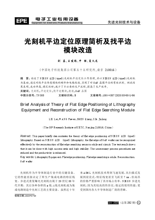
收稿日期:2020-04-20光刻机平边定位原理简析及找平边模块改造刘磊,王发稳,申强,夏久龙(中国电子科技集团公司第五十五研究所,南京210016)摘要:论述了NIKON i12D (type3)光刻机平边定位工作原理,并以NIKON i12D (type3)光刻机为基础,通过对找平边传感模块的硬件和电路改造,实现了对GaN 晶圆平边的有效识别。
测试结果表明,成功率高,稳定性好;减少了不必要的生产流程,提高了生产效率。
关键词:光刻机;平边定位;找平边模块;改造;GaN 晶圆中图分类号:TN305文献标识码:B文章编号:1004-4507(2020)03-0041-06Brief Analysis of Theory of Flat Edge Positioning of LithographyEquipment and Reconstruction of Flat Edge Searching ModuleLIU Lei ,WANG Fawen ,SHEN Qiang ,XIA Jiulong (The 55th Research Institute of CETC,Nanjing 210016,China )Abstract:This paper briefly demonstrates the theory of flat edge positioning of NIKON i12D (type3)lithography.Based on NIKON i12D (type3)lithography,the flat edge of GaN wafer can be recognized effectively by the reconstruction of flat edge searching sensor module and circuit.The test result shows that it can be done with high success ratio and high stability.The unnecessary process procedures are reduced and the productivity is enhanced.Key words:Lithography Equipment ;Flat edge positioning ;Flat edge searching module ;Reconstruction ;GaN wafer光刻机作为半导体制造行业中的关键设备,它的性能直接决定了所生产集成电路的特征线宽。
- 1、下载文档前请自行甄别文档内容的完整性,平台不提供额外的编辑、内容补充、找答案等附加服务。
- 2、"仅部分预览"的文档,不可在线预览部分如存在完整性等问题,可反馈申请退款(可完整预览的文档不适用该条件!)。
- 3、如文档侵犯您的权益,请联系客服反馈,我们会尽快为您处理(人工客服工作时间:9:00-18:30)。
VESA ConfidentialDisplayPort Alternate Mode for USB Type-C Connector Messaging Document Draft 0C Wiley 2014 07 151.The new USB Type-C connector announced by (the USB Implementer Forum?)supports the VESA DisplayPort™ Standard for audio/video transmission.2.With the DisplayPort Alternate Mode, the USB Type-C connector becomes thesingle system connection point for data, AV interface, and power. DisplayPortenables the USB Type-C connector to support video resolutions of 4K and beyond.3.Devices such as PCs, tablets and phones can use the DisplayPort Alternate Mode todeliver video to a display, or multiple displays, through the USB Type-C connector.Such devices will be able to drive existing DisplayPort displays using a Type-C to DisplayPort adaptor cable. Using the DisplayPort Alternate Mode, Video adaptors will also be available to drive HDMI, DVI, and VGA displays.4.Displays can also use the DisplayPort Alternate Mode to accept an AV input usingthe USB Type-C connector. Such displays can be driven by existing DisplayPort Sources using the same Type-C to DisplayPort adaptors cables.5.In a configuration where the both the video source and display use the USB Type-Cconnector, one cable can be used to deliver video, data and power. With thisconfiguration, for example, the display can serve as a USB hub and a power source for the connected laptop, tablet, or phone, and will simultaneously provide the video display and audio reproduction from the connected device.6.DisplayPort is a video interface standard administered by VESA, the VideoElectronics Standards Association. DisplayPort is the new generation A/V interface developed by the GPU/display industry segment and currently undergoing rapid market adoption. DisplayPort enables high display performance and versatility, a high degree of system integration, and greater interoperability between variousdevice types.7.The development of compliance testing specifications for the DisplayPort AlternateMode are currently underway at VESA. USB Type-C adopters will be able receive certification testing for both USB and the DisplayPort Alternate Mode at the same Certified Test Center. (Should we mention VESA PlugTests?)8.The DisplayPort Standard uses a unique packet-based protocol for A/V data. Theextensibility of the DisplayPort protocol has led to the development of uniquecapabilities such as Multi-Stream Technology that allows the support of multiple displays from a single video port.9.The extensible and flexible protocol of DisplayPort has led to its adoption into otherstand ards including VESA’s Embedded DisplayPort (eDP) Standard, VESA’sMobility DisplayPort (MyDP) Standard, VESA’s DockPort Standard, Intel’sThunderbolt interface, and now for the USB Type-C interface.10.DisplayPort electrical characteristics are similar to USB electrical characteristics,allowing the standards to share the same connector, cable, and device interface circuits. And like USB, DisplayPort was developed to be compatible with advanced sub-micro semiconductor technology, enabling high system integration and low power consumption.11.DisplayPort AV interface is scalable and will continue to evolve to meet therequirements of future displays. When used as an Alternate Mode on the USB Type-C connector and cable, the number of high speed data channels assigned to DisplayPort vs. USB can vary depending on the needs of the display and datatransfer requirements. (do we want to expand on this in regards to exampleresolution / data rate combinations?)12.To maximize backward compatibility, DisplayPort was designed to support legacydisplays such has HDMI, DVI and VGA through the use of protocol adaptors. This capability is utilized by USB Type-C connector as well.13.By having a very low EMI / RFI (Radio Frequency Interference) profile, DisplayPortwas designed to minimally interfere with system wireless functions. This is done through the use of a special data pseudo-randomizing algorithm, and it enables sleeker device designs by reducing shielding requirements while it maximizeswireless sever performance.14.With the DisplayPort Alternate Mode, the highest degree USB performance and A/Vinterface performance is now available on a single versatile miniature connector, along with system power.15.The DisplayPort Alternate mode has been defined by industry AV experts who haveknowledge and experience in both USB and DisplayPort technology and standard development.VESA Confidential。