Control of hydrogen photoproduction by the proton gradient generated by cyclic electron flow阅读笔记
光子晶体水凝胶的英文
光子晶体水凝胶的英文Photonic crystal hydrogels are pretty cool materials. They're like the combo of two amazing things: photonics and hydrogels. You know, photonics deals with light and its interaction with matter, while hydrogels are those super-absorbent polymers that can hold a lot of water.When you put them together, you get something that can manipulate light in a really unique way. Imagine being able to control how light passes through a material just by changing its water content. That's what photonic crystal hydrogels allow you to do.These materials are also really responsive. They can change their properties based on external stimuli like temperature or pH. So, not only can you control light, but you can also make the material respond to its environment.Photonic crystal hydrogels are super versatile, too. You can use them in sensors to detect chemicals or indisplays that change color based on some input. The possibilities are endless!Plus, they're just so fascinating to look at. The way the light dances through the crystal structure is like a mini light show. It's like nature's own version of a laser light display, but much more subtle and elegant.In a nutshell, photonic crystal hydrogels are a marriage of science and beauty. They're not just useful materials; they're also a visual treat. Who knows, maybe one day we'll see them everywhere, from our smartphones to our homes, adding a bit of magic to our daily lives.。
超高压辅助酶解法改性汉麻分离蛋白及其理化性质的研究

刘容旭,李春雨,王语聪,等. 超高压辅助酶解法改性汉麻分离蛋白及其理化性质的研究[J]. 食品工业科技,2023,44(19):99−107.doi: 10.13386/j.issn1002-0306.2023010016LIU Rongxu, LI Chunyu, WANG Yucong, et al. Study on the Modification and Physicochemical Properties of Hemp Protein Isolate by Ultra-High Pressure Assisted Enzymatic Hydrolysis[J]. Science and Technology of Food Industry, 2023, 44(19): 99−107. (in Chinese with English abstract). doi: 10.13386/j.issn1002-0306.2023010016· 研究与探讨 ·超高压辅助酶解法改性汉麻分离蛋白及其理化性质的研究刘容旭1,李春雨2,王语聪2,谢智鑫2,谢宜桐2,李双鹏2,刘丹怡1, *,韩建春2,*(1.黑龙江省绿色食品科学研究院,黑龙江哈尔滨 150028;2.东北农业大学 食品学院,黑龙江哈尔滨 150030)摘 要:本研究以汉麻分离蛋白(Hemp Protein Isolate ,HPI )为原料,通过超高压辅助酶解反应对HPI 进行改性,以溶解度和水解度为判定指标筛选酶解改性反应最佳条件,并探究超高压辅助酶解反应对酶解产物溶解性、起泡性、乳化性、持水性、持油性的影响。
结果表明,HPI 酶解反应最适条件为:加酶量(复合蛋白酶)5000 U/g 、酶解改性pH8.0、酶解改性温度55 ℃、酶解改性时间50 min 。
以HPI 为对照,当压力为200 MPa 时,酶解产物的溶解度、起泡性、乳化性、持油性最高,压力为100 MPa 时,泡沫稳定性最好,酶解后的乳化稳定性存在不同程度的下降,压力为0.1 MPa 时其持水性达到最大值。
Hydrogen Production by the High Temperature Combination of the Water GasShift
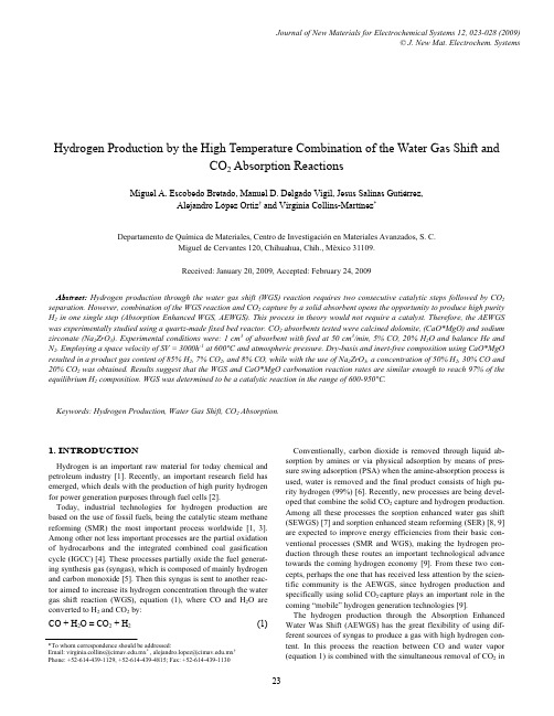
CO + H2O = CO2 + H2
(1)
*To whom correspondence should be addressed: Email: virginia.collins@.mx* , alejandro.lopez@.mx†
Phone: +52-614-439-1129, +52-614-439-4815; Fax: +52-614-439-1130
Keywords: Hydrogen Production, Water Gas Shift, CO2 Absorption.
1. INTRODUCTION
Hydrogen is an important raw material for today chemical and
petroleum industry [1]. Recently, an important research field has
regeneration of the carbonated metal (MeCO3) with pure CO2 can produce a high purity stream of this gas through the reverse reac-
catalyst for this to proceed. Additionally, as a result of the CO2
removal during the WGS reaction the system reaches the thermo-
dynamic equilibrium, thus producing a higher hydrogen content in
Miguel A. Escobedo Bretado, Manuel D. Delgado Vigil, Jesus Salinas Gutiérrez, Alejandro López Ortiz† and Virginia Collins-Martínez*
Photocatalytic hydrogen evolution from CdS–ZnO–CdO systems under visible light irradiation alysts
reserved.
1. Introduction
The scarcity of fossil fuels and the pollution issues associated with their use have focused the attention of the scientific, governmental and industrial communities on the search for alternative energy systems. The conversion of solar energy into hydrogen via the water splitting process assisted by photosemiconductor catalysts is one of the more interesting ways achieving clean and renewable energy systems [1,2]. Since the pioneering work by Fujishima and Honda [3], several types of semiconductors involving oxides (SrTiO3 [4], NaTaO3 [5],
用于光电化学水分解的光电极氧空位调节综述
综述 (94 ~ 103)用于光电化学水分解的光电极氧空位调节综述俞立豪,邵卫卫(江苏澄信检验检测认证股份有限公司,江苏 江阴,214400)摘要:光电化学(PEC )分解水制氢是一项有望取代化石燃料的绿色能源生产策略. 传统光电极由于其光生载流子的快速复合和缓慢的动力学会导致水分解性能不佳. 在电极材料中注入氧空位可调节光电极的电子和光学性质,从而有助于光电极中固有缺陷的形成. 已有研究表明,将氧空位引入光电极是增强其PEC 分解水性能的有效方法. 对于不同类型的半导体光电极材料,介绍了通过氢气还原、等离子体处理和过氧化氢处理引入氧空位的方法以及氧空位影响光电极PEC 性能的研究进展. 总结了基于新的表征技术对氧空位的深入理解和新的发现,并对光电极氧空位调节策略及应用研究进行了展望.关键词:光电化学;分解水制氢;光电极;氧空位中图分类号:O657. 1 文献标志码:A 文章编号:1006-3757(2024)02-0094-10DOI :10.16495/j.1006-3757.2024.02.004Review of Oxygen Vacancy Regulation in Photoelectrodes forPhotoelectrochemical Water SplittingYU Lihao , SHAO Weiwei(Jiangsu Chengxin Inspection , Testing and Certification Co. Ltd., Jiangyin 214400, Jiangsu China )Abstract :Photoelectrochemical (PEC) water splitting to produce hydrogen is a green energy production strategy that is expected to replace fossil fuels. Conventional photoelectrodes could lead to poor performance of water splitting due to their fast recombination and slow kinetics of photogenerated carriers. Injecting oxygen vacancies into the electrode materials can regulate the electronic and optical properties of the photoelectrodes, thus contributing to the formation of inherent defects in the photoelectrodes. It has been shown that introducing oxygen vacancies into photoelectrodes is an effective method to enhance the water splitting performance of PEC. For different types of semiconductor photoelectrode materials, the methods of introducing oxygen vacancies through hydrogen reduction, plasma treatment and hydrogen peroxide treatment, and the research progress of the effect of oxygen vacancies on the performance of photoelectrodes PEC were introduced. The in-depth understanding and new discoveries of oxygen vacancies based on new characterization techniques were summarized, and the strategies and applications of oxygen vacancies regulation in photoelectrodes were prospeced.Key words :photoelectrochemical ;water splitting for hydrogen production ;photoelectrode ;oxygen vacancy近年来,快速增长的工业和不断增加的全球人口是造成能源短缺和环境污染的关键因素. 因此,为确保人类社会的长期和可持续发展,迫切需要开发环境友好和可再生的绿色能源和环境治理技术.氢气被认为是一种传统化石燃料很好的替代品,它可以通过烷烃的蒸汽重整和水分解等方式生产[1].然而,烷烃重整过程中会释放出一氧化碳(CO )、二氧化碳(CO 2)等副产物,造成严重的空气污染. 此外,收稿日期:2023−12−20; 修订日期:2024−03−07.作者简介:俞立豪(1994−),男,硕士研究生,研究方向:光电化学分解水,E-mail :******************.第 30 卷第 2 期分析测试技术与仪器Volume 30 Number 22024年3月ANALYSIS AND TESTING TECHNOLOGY AND INSTRUMENTS Mar. 2024烷烃重整需要高温高压才能获得更好的效率,这不符合绿色能源的策略. 由于地球上有丰富的水资源且水分解过程中不会产生其他污染物,因此分解水制氢是一项很有前景的策略.人类每年消耗约14 TW 的能源,其中85%来自传统的化石燃料. 然而,太阳每年可以向地球输送10 000 TW 能量,因此太阳能的有效利用将大大缓解能源危机. 太阳能向氢气的转化已通过以下途径成功实现:光催化(PC )水分解、光电化学(PEC )水分解和太阳能电池供电的电化学水分解[2]. 在各种现有技术中,基于半导体的光电催化技术具有巨大的潜力,它既能直接利用太阳能生产有价值的化学燃料(如氢燃料),又能降解有害污染物. 1972年,Fujishima 和Honda [3]首次发现TiO 2作为n 型半导体可以在短波长下(415 nm 以下)分解水. 从那时起,许多研究人员对半导体PC 水分解产生了兴趣. 低成本和低能耗(无需电力)是光催化的主要优点.图1(a )显示了一步PC 水分解的原理. 在光照下,价带(VB )的电子可以被激发到导带(CB ),而VB 会留下空穴,光激发的电子-空穴迅速分离并迁移到光电极表面进行氧化还原反应. 对于n 型半导体光阳极,光生空穴会积聚在半导体表面然后参与表面的氧化反应,而电子经过外部电路迁移到对电极上,参与还原反应. 相反,对于p 型半导体光阴极,光生电子积聚在半导体表面然后参与表面的还原反应.值得注意的是,半导体的带隙必须大于水分解的电势(1.23 V ),且半导体光阳极的VB 顶部应比析氧的电势更正,而光阴极的CB 底部应比析氢的电势更负,满足这样的条件才可进行分解水反应. 两步水分解是另一种机制[图1(b )],其有两种不同的半导体,并伴随氧化还原反应,其中一种催化剂通过水还原产生氢气,而另一种催化剂通过水氧化产生氧气.PEC 水分解机理与PC 水分解机理相似. PEC 水分解不仅需要太阳能,还需要偏压,如图1(c )~(e )所示. 在PEC 系统中,VB 的位置应该比水氧化的位置更正,以确保氧化反应,同时电子从外部电路迁0(a)(b)(−)(−)H +/H 2H +/H2H +/H 2H +/H 2H +/H 2O 2/H 2O VBCB CB CB CB VBVB VB VB PhotoanodeCounter electrodePhotocathodePhotocathodePhotocathodeCounter electrodePhotocatalyste −e −(c)(d)(e)h +Band gap (E g )2H +2H 2OO 2+4H +O 2/H 2OO 2/H 2OO 2/H 2OO 2/H 2O1.23 V 1.23 V 1.23 V H 2H +/H 2Ox/Red Ox/Red (1.23 V)(+)O 2/H 2O (0 V)h vh vh vh vh v h vh vCBCBVBH 2 evolution photocatalystO 2 evolution photocatalyst e−e −e −e −e −e −e −e −e −e −e −e −e −e −h +h +h +h +h +h+(+)+1.0+2.0P o t e n t i a l /V v s . N H E (p H 0)P o t e n t i a l /V v s . N H E (p H 0)+3.0图1 (a )一步和(b )两步光催化分解水的能量图,使用(c )光阳极、(d )光阴极和(e )光阳极和光阴极串联连接的PEC 水分解[4]Fig. 1 Energy diagrams of (a) one-step and (b) two-step photocatalytic decomposition of water, PEC water decompositionusing (c) photoanode, (d) photocathode, and (e) photoanode and photocathode[4]第 2 期俞立豪,等:用于光电化学水分解的光电极氧空位调节综述95移到电极,在光阴极上发生还原反应. 或者,光阳极和光阴极可以串联连接,形成串联,类似于PC系统的两步水分解[4]. PEC分解水技术吸引了大量科研人员的关注,并在光阳极方面取得了卓越的成果. 例如,Zhao等[5]报道了在100 mW/cm2光照、1 mol/L KOH(pH=13.6)条件下,OEC/CTF/BaTiO3(OEC=oxyhydroxide oxygen evolution cocatalyst,CTF=covalent triazine framework)光阳极在1.23 V vs. RHE(Reversible Hydrogen Electrode, RHE)下显示出0.83 mA/cm2的最高光电流密度,与BaTiO3(0.14 mA/cm2)相比,提高了5.93倍,高于已报道的光阳极.类似地,Sun等[6]合成了BiVO4@NiFe-LDHs/Ru(NiFe-LDH=NiFe layered double hydroxide)光阳极,由于单原子Ru和NiFe-LDH的协同作用,在1.23 V vs. RHE条件下,BiVO4@NiFe-LDHs/Ru (4.65 mA/cm2)实现了比BiVO4(1.70 mA/cm2)高得多的光电流密度,其性能也优于大多数报道的基于BiVO4的光阳极.通常,光生载流子的快速复合和缓慢的动力学会导致PC水分解性能不良. 相比之下,PEC水分解具有更大优势,可以集成PC和电催化的特性,水分解过程可以通过光和偏压参数进行调控,且水分解产生的H2和O2可以同步分离和收集. 此外,PEC 水分解往往具有优于电催化和PC水分解的特性,因为它需要更低的过电势,可以选择各种半导体来制备光电极,包括金属氧化物、金属硫化物、金属氮化物和钙钛矿氧化物. TiO2(带隙为3.0~3.2 eV)、ZnO(带隙为3.37 eV)和SnO2(带隙为3.5 eV)等金属氧化物因价格低廉、储量丰富、无毒等特性而受到广泛研究[7]. 然而,大的带隙和载流子的快速复合仍然限制了金属氧化物的实际应用. 金属硫化物CdS和金属氮化物Ta3N5具有相对较窄的带隙,可以更好的吸收太阳光并快速产生光生空穴-电子分离和传输,但CdS在持久光照下会产生严重的光腐蚀. 在能带理论中,Ta3N5理论上可以自发地分解水,作为单一光电极,其具有~15%的最大太阳能-氢气转换效率. 但是,一方面Ta3N5较差的电子性能导致PEC过程中的耐久性较差. 另一方面,表面氧化引起的光降解会导致光电极性能急剧下降. 近年来,钙钛矿氧化物因其优异的稳定性和柔性带隙而出现在公众视野中,但其低电导率和不良缺陷成为关键问题.鉴于上述PEC的局限性,人们提出了多种策略:表面工程、异质结、元素掺杂. 表面工程可以提高反应物的吸附和活化能力,使表面的电子或空穴能够有效地参与还原或氧化反应. 异质结通常涉及两个半导体A和B. 半导体A的CB和VB能级高于半导体B的相应能级. 因此,光生电子会转移到半导体B,而光生空穴在光照射下在半导体A处迁移,导致电子-空穴对的空间分离. 在半导体中掺杂客体元素可以提高半导体的导电性,减少复合中心的数量,从而提高光生载流子的寿命和光电导性. 另外,可以通过注入氧空位来形成光电极中的固有缺陷,从而有助于调节其电子和光学性质. 通过处理原始TiO2,可以从TiO2基体中部去除晶格氧,从而产生氧空位(图2). 由于氧空位的高活性,光电极具有非常低的光电流饱和电势,这表明电荷分离和传输非常有效. 实验和理论研究都表明,氧空位有利于从对电极提取光生电子,并有利于不同电荷状态下的结构弛豫[8].(a)(b)b ba ac c图2 (a)原始TiO2,(b)具有氧空位的TiO2模型[8]Fig. 2 Models of (a) original TiO2and (b) TiO2withoxygen vacancies[8]因半导体的种类丰富,形貌的不同将直接影响其对PEC分解水性能的影响. 一般来说,量子点、纳米线以及超薄纳米片是半导体常见的三种形貌,基于大量的研究成果,这篇综述旨在对不同维度半导体中氧空位调控的进展进行概述,其中包括半导体的合成制备及氧空位对半导体光电化学性能的影响,并对氧空位的新表征技术进行介绍.1 氧空位调控的进展1.1 零维材料中的氧空位广义上讲,量子点是一种常见的零维材料. 作为一种很有前途的光电材料,由于其生态友好、成本低、合成简单、化学惰性和上转换光致发光特性等优点,引起了人们的广泛关注. 量子点作为可见光增感剂可以显著提高可见光范围,从而直接提高96分析测试技术与仪器第 30 卷光电流密度. 最重要的是,量子点中的氧空位可以促进空穴转移,从而有效地降低水氧化反应的能量势垒,进一步改善光电极表面的电荷分离效率.使用氢气还原样品以获得氧空位是一种简单有效的策略. Co 3O 4作为一种非贵金属,其具有氧空位的量子点表现出高效的催化性能. Tong 等[9]通过简单的无表面活性剂方法合成了原始的Co 3O 4量子点(即P-Co 3O 4), 然后将原始的Co 3O 4量子点置于5% H 2/95% N 2的混合气体气氛下. 将样品分别在170和200 ℃的温度下加热1 h ,以制备具有不同程度氧缺陷的Co 3O 4量子点(即Co 3O 4-170,Co 3O 4-200). 为证实氧空位的存在并考察氧空位对催化性能的影响,使用高分辨率X 射线光电子能谱(XPS )、电子顺磁共振谱(EPR )等方法进行表征. 如图3(a )所示,P-Co 3O 4和具有氧空位的Co 3O 4的Co2p XPS 谱图都显示如下特征峰:位于779.9 eV 和794.9 eV 的两个峰可归属于Co (III ),而位于781.6 eV 和797.8 eV 的两个峰可归属于Co (II ). 此外,在氢还原处理后,Co (II )的浓度显著高于P-Co 3O 4的浓度,因为在H 2气氛中形成了氧空位. 三种样品的O1s 谱图如图3(b )所示,其中Co 3O 4-200的氧空位比例大于Co 3O 4-170和P-Co 3O 4,表明在Co 3O 4-200样品中形成了更丰富的氧空位. EPR 谱可以进一步研究半导体衬底中相关的氧空位信息. 如图3(c )所示,P-Co 3O 4的信号在谱图上可以忽略,而其他两个样品显示出较强的EPR 信号,更重要的是,Co 3O 4-200显示出最高的强度. 这一结果与XPS 研究结果一致.以上就是氧空位形成的证明. 接下来讨论其性能,如图3(d )所示,与Co 3O 4-170和P-Co 3O 4相比,Co 3O 4-200样品显示出最高的电导率,表明丰富的氧空位促进了催化剂界面中的电子转移,从而提高了样品的电导率.除了量子点,纳米颗粒也是常见的零维材料.Zhang 等[10]用类似氢气还原方法(即在300 ℃、3 2003 400805(a)(b)(c)(d)P-Co 3O 4Co 3O 4-170Co 3O 4-200Co 3O 4-170P-Co 3O 4Co 3O 4-200P-Co 3O 4Co 3O 4-200Co 3O 4-170P-Co 3O 4Co 3O 4-200Co 3O 4-170Co (Ⅲ)Co (Ⅱ)O1 s I n t e n s i t y /a .u .I n t e n s i t y /a .u .R e s i s t i v i t y /(105 Ω·m )R e s i s t i v i t y /(105 Ω·m )I n t e n s i t y /a .u .800795Binding energy/eVBinding energy/eV 7907857805281001.51.00.507550255315345373 600Magnetic field/mTTemperature/KTemperature/K3 8004 000280320360380400360400图3 Co 3O 4-200、Co 3O 4-170和P- Co 3O 4样品的(a )Co2p 和(b )O1s 的高分辨率XPS 谱图,(c )Co 3O 4-170、Co 3O 4-200和P-Co 3O 4样品的EPR 谱图,(d )Co 3O 4-200、Co 3O 4-170和P-Co 3O 4样品的温度相关电导率[9]Fig. 3 High resolution XPS spectra of (a) Co2p and (b) O1s of Co 3O 4-200, Co 3O 4 -170 and P- Co 3O 4 samples, (c) EPR spectraof Co 3O 4-170, Co 3O 4-200 and P-Co 3O 4 samples, (d) temperature dependent conductivity of Co 3O 4-200, Co 3O 4-170 andP- Co 3O 4 samples[9]第 2 期俞立豪,等:用于光电化学水分解的光电极氧空位调节综述9795% Ar 和5% H 2气体氛围下)处理BiFeO 3纳米颗粒,并获得了令人满意的结果. 其报道证明经不同高温时间处理的样品具有不同的性质. 首先,随着处理时间的增加,氧空位的数量增加,PEC 性能提高. 当达到峰值位置(处理时间30 min )时,光电流是原始BiFeO 3的三倍以上. 随后,处理时间继续延长,导致过多的氧空位作为空穴-电子对的电荷湮灭中心,PEC 性能下降. Zhao 等[11]从Co 3O 4纳米颗粒中氧空位界面结构处形成的能量入手,证实作为助催化剂的高岭石(kaolinite )表面丰富的羟基可以诱导金属氧化物中氧空位的形成. 他们选择NaBH 4作为还原剂来产生氧空位,在高温下处理样品,分别获得经NaBH 4还原的5%-Co 3O 4/kaolinite (即5%R-Co 3O 4/kaolinite )和5%-Co 3O 4/kaolinite. 通过XPS 表征,5%R-Co 3O 4/kaolinite 样品中Co 2+/Co 3+的比例最高,而5%-Co 3O 4R/kaolinite 和5%-Co 3O 4/kaolinite (未处理样品)样品中Co 2+/Co 3+的比例近似相等. 这一结果不仅证实了还原剂NaBH 4可以产生氧空位的事实,而且还证明了高岭石可作为助催化剂参与反应. 可以看出,H 2和NaBH 4在高温下可以去除晶格氧并产生氧空位, 氧空位的数量和其他材料的助催化作用有待研究人员进一步探索.1.2 一维材料中的氧空位纳米线是常用的一维半导体. Wang 等[12]通过水热法在氟掺杂氧化锡(FTO )玻璃基板上制备了金红石型TiO 2纳米线阵列,然后使用氢退火获得氢处理的金红石型TiO 2(即H: TiO 2). 在不同的退火温度下,样品的颜色也不同,如图4(a )所示,随着温度的升高,H: TiO 2从白色(未处理的样品)变为黄绿色(350 ℃),最后变为黑色(450 ℃或以上). 为了研究氢处理对TiO 2 PEC 性能的影响,在光照下对原始TiO 2和H: TiO 2(400 ℃)进行了线性扫描[图4(b )],表明H: TiO 2(400 ℃)的光电流约为原始TiO 2的两倍. XPS 显示,氢处理后的样品中没有杂质掺杂,因0.7(b)(c)(d)0.60.50.4H: TiO 2H: TiO 2H: TiO 2 (350 ℃)TiO 2TiO 2Dark scansPotential (V) vs. Ag/AgCl0.30.20.10P h o t o c u r r e n t d e n s i t y /(m A /c m 2)−0.16.0 3.02.52.01.51.00.55.04.03.02.01.001/C 2/(1010 F −2 ·c m 4)1/C 2/(107 F −2 ·c m 4)0.70.60.50.40.30.20.1030020406080100350400450500550600650−0.8450500Wavelength/nmWavelength/nmTiO 2350 ℃350 ℃400 ℃400 ℃450 ℃450 ℃550600650I P C E /%I P C E /%−0.6−0.4−0.200.20.40.6Potential (V) vs. Ag/AgCl−0.9−1.0−0.8−0.7−0.5−0.6Potential (V) vs. Ag/AgCl−0.9−1.0−0.8−0.7−0.5−0.6图4 (a )不同温度下在氢气中退火的原始TiO 2和H: TiO 2纳米线的照片,(b )在400 ℃氢气中退火的原始TiO 2和H:TiO 2纳米管阵列收集线性扫描,(c )原始TiO 2和在350 ℃退火的H:TiO 2纳米线的Mott-Schottky 图,(d )在350、400和450 ℃下制备的原始TiO 2和H:TiO 2纳米线的IPCE 光谱[12]Fig. 4 (a) Photos of original TiO 2 and H: TiO 2 nanowires annealed in hydrogen at different temperatures, (b) collect linear scans of original TiO 2 and H: TiO 2 nanotube arrays annealed in hydrogen at 400 ℃, (c) Mott-Schottky plots of original TiO 2and H: TiO 2 nanowires annealed at 350 ℃, (d) IPCE spectra of original TiO 2 and H: TiO 2 nanowires prepared at 350, 400and 450 ℃[12]98分析测试技术与仪器第 30 卷此可以推断H: TiO2中氧空位的形成. TiO2作为n型半导体,所有样品在Mott-Schottky图中都具有正斜率[图4(c)]. 重要地是,与TiO2相比,H: TiO2纳米线样品显示出明显更小的Mott-Schottky图斜率,表明供体密度增加. 此外,供体密度随着氢处理温度的升高而增加. 为了找出产生氧空位的最佳温度,除了测量光电流外,还使用入射光子-电流转换效率(IPCE)来表征光阳极,因为它显示出更好的光转换效率. IPCE值通过下式计算[13]:其中I是特定波长下测量的光电流密度,λ是入射光的波长,J light是特定波长下测量的辐照度.如图4(d)所示,所有H: TiO2的效率远高于原始TiO2的效率,并且350 ℃退火制得的H: TiO2的IPCE 在300~370 nm 时超过95%,表明样品在300~370 nm具有高PEC活性. 然而,由于金红石TiO2的带隙为3.0 eV,IPCE值在370~420 nm迅速降低,表明其在可见区域中几乎没有响应. 总之,Wang的工作已经证明,氢处理可以产生氧空位,从而显著提高TiO2材料作为PEC水分解光阳极的性能.2019年,Li等[14]报道到N掺杂的碳量子点可以稳定TiO2纳米线的氧空位,并提高可见光区域的PEC性能. 通过光电流测试,具有氧空位的N掺杂的碳量子点TiO2纳米线阵列(NCDs/TiO2-NA-Vo,N-doped carbon dots/Vo-rich TiO2nanowire array,其中Vo= oxygen vacancies)光电极表现出的光电流密度是具有氧空位TiO2纳米线阵列(TiO2-NA-Vo)、N掺杂碳量子点TiO2纳米线阵列(NCDs/TiO2-NA)以及TiO2纳米线阵列(TiO2-NA)的1.5倍、2倍和3倍以上. 碳量子点(CQDs)由于其独特的上转换发光能力(近红外光上转换为可见光),不仅可以提高太阳能的吸收和转换能力,还可以减小原始TiO2的带隙. 在光照射(波长>420 nm)下,NCDs/TiO2-NA-Vo光电极表现出比其他光电极高得多的IPCE.NCDs/TiO2-NA-Vo的优异性能还包括电化学阻抗谱和稳态光致发光光谱,证明了有效的电子-空穴分离效率. 总之,元素的掺杂和氧空位的产生对半导体催化剂具有协同作用,共同提高了PEC的活性.同样,基于协同效应,Yin等[15]使用具有氧空位的双金属硫化物来提高水分解性能. 该团队首先在氮气气氛中煅烧NiCo2O4纳米线(即NiCo2O4 NWs)和硫粉,获得了具有氧空位的目标产物NiS2/CoS2界面多孔纳米线(即NiS2/CoS2-O NWs). 经线性扫描伏安法研究表明,在相同电压下,电流密度NiS2/CoS2-O NWs> NiS2/CoS2-NWs>NiCo2O4NWs,明显地,氧空位的捕获电子和双金属硫化物的多孔和高活性位点特性共同提高了催化性能.传统的还原方法可以使大多数金属氧化物或硫化物产生氧空位,但ZnO除外. Duan等[16]首次报道了通过电化学还原处理ZnO纳米线. 由于ZnO 的光捕获能力差以及FTO与还原剂之间的不良反应导致电极电导率急剧下降,因此,一般的化学还原方法无法获得像TiO2这样良好的氧空位靶. 电化学还原方法是在标准的三电极体系下,用恒定电压还原ZnO纳米线以获得氧空位. 结果表明,具有氧空位的ZnO在紫外区域的吸收波长略有红移,这可能与氧空位的浓度有关.除了传统的氢还原方法外,本节还报道了基于一维特殊材料的特殊电化学还原方法产生氧空位的情况. 氧空位本身在半导体中起着一定的作用,为了进一步提高PEC的性能,可以采用掺杂或多孔结构设计.1.3 二维材料中的氧空位二维纳米片为PEC性能增强提供了独特的平台,其二维结构可产生大量的活性位点并减少少数载流子扩散路径长度[17]. 由于二维纳米片超薄的结构,使其具有高载流子迁移率和高光吸收效率,增加了载流子收集和界面氧化还原反应的表面积(增加活性位点的数量),调整了电子的性质(改变催化剂的表面性质)从而获得强光催化活性. 例如赤铁矿具有带隙较窄(2.2 eV)和储量丰富的优点. 如前所述,用氢气在高温下退火的样品可以获得丰富的氧空位,但高温需要更多的能量. Zhu等[18]报道了通过空气等离子体方法在超薄α-Fe2O3纳米片中产生了氧空位的策略. 相对低功率的等离子体处理可以在不改变形貌的情况下使赤铁矿纳米片的表面被活化. 在报告中,使用两种等离子体功率对所制备的赤铁矿纳米片(as-prepared)进行处理,分别为中等功率(PM,10.5 W)和高功率(PH,18 W). 结果表明与原始赤铁矿纳米片的形貌相比,经PM和PH等离子体处理后的样品没有显示出明显的变化. Mott-Schottky测量用于研究等离子体处理的效果,如图5(a)所示,从图中可以看出,PH样品的IPCE 值在350 nm处达到最大,约为15.6%,高于PM和第 2 期俞立豪,等:用于光电化学水分解的光电极氧空位调节综述99原始样品的值(PM=12%,As-prepared =1.43%,在350 nm 处). 观察到的增强的IPCE 值可归因于等离子体处理在样品中引入的高密度氧空位. 除此之外,还通过光辅助电沉积技术在PH 样品表面进行Co-Pi 沉积(Co-Pi/PH ),并采用线性扫描伏安法(LSV )测试原始赤铁矿纳米片、PM 、PH 、Co-Pi/PH 样品的光电流,结果如图5(b )所示. 显然,与原始纳米片样品相比,等离子体处理的样品具有更高的光电流,尤其是经电沉积的Co-Pi/PH 样品. Co-Pi 是与赤铁矿结合使用的助催化剂之一,具有最高的吸收系数.值得注意地是,Co-Pi/PH 使起始电位急剧向负值移动,表明大多数入射光到达赤铁矿层可以增强活性.因此,助催化剂和通过等离子体处理引入的氧空位对半导体性能起到协同作用. 图5(c )~(e )分别提供了原始赤铁矿纳米片、PM 、PH 样品O1s 峰的信息,529.9 eV (O1s )处的主峰是由氧原子和金属结合形成的,532 eV 左右的肩峰则是由具有低氧配位的缺陷(即氧空位)引起的,且不同样品存在差异. 与主氧化物峰相比,原始赤铁矿纳米片、PM 和PH 样品的肩峰强度逐步增加. 这些结果表明,经等离子体处理后的氧空位确实被引入到赤铁矿纳米片中,并且氧空位的密度随着功率的增加而增加. 与空气等离子体处理类似,Liu 等[19]首次报道了采用水等离子体处理剥离CoFe 层状双氢氧化物(LDHs )纳米片并产生氧空位的方法. LDHs 具有较高的催化活性,但由于层状堆叠结构限制了活性位点的暴露,因此需要对其进行剥离以暴露更多的活性位点. 与传统剥离方法相比,使用水等离子体法剥离的效率更高.等离子体可以部分蚀刻层之间的阴离子以剥离纳米片,并腐蚀金属氢氧化物层以产生氧空位和更多的活性位点.此外,Liu 等[20]报道了用H 2O 2处理板状WO 3薄膜,获得表面氧空位的方法. 此方法具有低温处理的优点. 在WO 3表面上形成的氧空位显示出比原始WO 3片更高的PEC 性能. 在H 2O 2处理之前,原始样品在EPR 中没有信号,但经H 2O 2处理后的样品在测试中具有非常强的信号,因此可以推断形成氧空位的可能性. 然后,采用XPS 进一步表征了经不同H 2O 2处理时间的板状WO 3薄膜(分别经H 2O 2处理0、10、30、60、90 min )的O1s 和W4f. 在XPS4.5(a)(b)(c) As-prepared(d) PM(e) PH4.03.53.02.52.01.50.43504004505005500.50.60.70.80.9 1.0Potential (V vs. RHE)J /(m A /c m 2)1.1 1.2 1.3 1.4 1.5 1.6536536536534534534532532532530Binding energy/eVBinding energy/eVBinding energy/eV530530528O 1sO 1sO 1s532.1 eV oxygen vacancyAs-prepared PM PHCo-Pi/PHAs-prepared PM PH@1.23 V vs. RHE5285285265265261.00.516141210864I P C E /%20Wavelength/nmI n t e n s i t y /a .u .I n t e n s i t y /a .u .I n t e n s i t y /a .u .图5 制备的、PM 和PH 赤铁矿纳米片样品的(a )Mott-Schottky 图,(b )J-E 曲线,(c )~(e )O1s 峰[18]Fig. 5 (a) Mott-Schottky plots, (b) J-E curves , (c) ~ (e) O1s peaks of as-prepared, PM and PH hematitenanoflakes samples[18]100分析测试技术与仪器第 30 卷的O1s 谱图中,有两个主峰:晶格氧(O L )和吸附氧(O A ). 随着H 2O 2处理时间的增加,O L /O A 拟合峰面积的比值逐渐减小,这可能是由于维持电荷平衡而吸附在缺氧区的氧离子或表面产生的羟基引起的,进一步证明了氧空位的存在. XPS 的W4f 谱图显示了类似的结果:经H 2O 2处理的WO 3的W4f 峰分别归因于W 6+和W 5+. W 5+/W 6+拟合峰面积的比值随处理时间的增加而增加,这表明越来越多的W 6+被氧空位还原. 经H 2O 2处理的WO 3的伏安法测试结果显示,其具有最大光电流密度(处理60 min ). 氧空位可以作为半导体的施主能级,但过多的氧空位会成为电子-空穴对的复合中心,这会带来副作用.IPCE 的结果表明,所有经H 2O 2处理的样品效率都高于原始WO 3. 但曲线中没有明显的红/蓝位移,这表明氧空位的存在可能不会扩展可见光区域,或者这种位移与氧空位的浓度有关.二维材料主要是纳米片或层状形态. 等离子体处理对层状薄片的阴离子剥离具有高效性. 同时,H 2O 2作为一种清洁还原剂,在低温下产生氧空位方面具有独特的优势.2 氧空位的新表征技术近年来,基于同步辐射的X 射线吸收光谱(XAS )已成为光电化学领域中一种更强大、更有效的工具,并对氧空位有了更深入的了解和新的发现.He 等[21]从Co 3O 4开始,分别用25 和50 keV 的氩离子辐射处理Co 3O 4,得到含氧空位的Co 3O 4(Co 3O 4-Ov )和多相CoO/Co 3O 4. 除了前面提到的XPS 和ESR (EPR )之外,还使用X 射线吸收近边结构(XANES )和扩展X 射线吸收精细结构(EXAFS )谱来进一步表征试验样品,收集了Co K-edge 的EXAFS 光谱,在Co 3O 4样品中测量到的Co 原子和相邻O 原子之间的键长为191 pm ,同时在CoO/Co 3O 4和Co 3O 4-Ov 样品中也发现了相同的键长. 此外,测得的208 pm 键长被认为是从CoO/Co 3O 4样品中获得的Co-O 键. 从配位数可以看出氧空位的存在. 与Co 3O 4相比,Co 3O 4-Ov 的Co-O 配位数为4.6,小于Co 3O 4样品的配位数为5. 电子结构是材料的重要参数. 因此,XANES 光谱也被用于研究电子结构,以进一步研究氧空位. 在大约780 和795 eV 处的XANES 峰分别被称为L3和L2峰,其响应电子从2p 3/2和2p 1/2跃迁到3d 轨道. 此外,Co 价态的降低是由于CoO/Co 3O 4和Co 3O 4-Ov 的Co-L 光谱中Co-L 边缘向较低光能的负转移. 理论计算还表明,CoO/Co 3O 4和Co 3O 4-Ov 的Co 2+/Co 3+比分别为1.4和1.3,高于Co 3O 4. 通过EXAFS 和XANES 两种表征方法,以及三种样品之间的比较,可以更准确地确认氧空位,并探索不同氩离子辐射对样品的影响.通过使用一种新的同步照明X 射线光电子能谱(SI-XPS )技术,Zhang 等[22]发现表面上的氧空位(surf-Vos )与水分子有很强的结合,并捕获氧原子,以实现表面晶格氧的各向异性自修复. 此外,由于富集的电子位于低配位的Ti 位点,幸存的亚表面Vos (sub-Vos )促进了从Ti 到O 原子的电荷激发.具有氧空位的TiO 2(Vo-TiO 2)的SI-XPS 结果显示,Vos 和Ti 3+分别在O1s 和Ti2p 区域出现明显的峰.当Vo-TiO 2与水分子接触时,氧空位峰和Ti 3+峰急剧下降,水(~533.3 eV )和OH (~532.1 eV )峰开始出现,表明氧空位的消失和Ti-O 键的复合. 此外,它们的峰值位置向高结合能移动. 在SI-XPS 光谱中可以检测到微弱的Ti 3+峰. 可以推断,样品吸水后的表面下存在一些氧空位. 在光照下,水峰消失,OH 峰增加,这意味着水开始分解为OH. 同时,还可以观察到峰位置向低结合能移动,这表明电子从水分子转移到TiO 2. 这些结果表明,TiO 2与水接触后,表面氧空位会自我修复,而sub-Vos 可能是析氢的活性位点. 为了进一步探索不同氧空位对TiO 2的影响,计算了氢解吸的吉布斯自由能(ΔG ). 在氢解吸过程中,sub-Vos 的ΔG 为-0.09 eV ,而surf-Vos 的能垒要求为0.30 eV ,表明质子解吸能力sub-Vos 优于surf-Vos. 同时,原始TiO 2的氢解吸过程的ΔG 为1.95eV. 显然,SI-XPS 表征和理论计算的结果表明,sub-Vos 是水分解析氢的活性位点.3 总结与展望总之,用于PEC 水分解的材料应该是低成本和有效的半导体光电极. 一般来说,过渡金属是合适的选择. 这篇综述从材料维度的角度总结了一些常见的半导体光电极材料引入氧空位的方法,并解释了氧空位的存在及其对提高PEC 性能的重要作用.与半导体选择的标准类似,需要一些好的策略来产生氧空位. 氢气的高温还原因简单性和清洁性吸引了研究人员关注. 但由于其高温的限制,研究人员第 2 期俞立豪,等:用于光电化学水分解的光电极氧空位调节综述101。
半导体一些术语的中英文对照

半导体一些术语的中英文对照离子注入机ion implanterLSS理论Lindhand Scharff and Schiott theory 又称“林汉德-斯卡夫-斯高特理论”。
沟道效应channeling effect射程分布range distribution深度分布depth distribution投影射程projected range阻止距离stopping distance阻止本领stopping power标准阻止截面standard stopping cross section 退火annealing激活能activation energy等温退火isothermal annealing激光退火laser annealing应力感生缺陷stress-induced defect择优取向preferred orientation制版工艺mask-making technology图形畸变pattern distortion初缩first minification精缩final minification母版master mask铬版chromium plate干版dry plate乳胶版emulsion plate透明版see-through plate高分辨率版high resolution plate, HRP超微粒干版plate for ultra-microminiaturization 掩模mask掩模对准mask alignment对准精度alignment precision光刻胶photoresist又称“光致抗蚀剂”。
负性光刻胶negative photoresist正性光刻胶positive photoresist无机光刻胶inorganic resist多层光刻胶multilevel resist电子束光刻胶electron beam resistX射线光刻胶X-ray resist刷洗scrubbing甩胶spinning涂胶photoresist coating后烘postbaking光刻photolithographyX射线光刻X-ray lithography电子束光刻electron beam lithography离子束光刻ion beam lithography深紫外光刻deep-UV lithography光刻机mask aligner投影光刻机projection mask aligner曝光exposure接触式曝光法contact exposure method接近式曝光法proximity exposure method光学投影曝光法optical projection exposure method 电子束曝光系统electron beam exposure system分步重复系统step-and-repeat system显影development线宽linewidth去胶stripping of photoresist氧化去胶removing of photoresist by oxidation等离子[体]去胶removing of photoresist by plasma 刻蚀etching干法刻蚀dry etching反应离子刻蚀reactive ion etching, RIE各向同性刻蚀isotropic etching各向异性刻蚀anisotropic etching反应溅射刻蚀reactive sputter etching离子铣ion beam milling又称“离子磨削”。
亚临界水色谱
advantages of PHW-LC
(1) higher separation speeds (lower backpressure);
(2) use of longer columns; (3) improved column efficiency; (4) extended detector selection.
It has also proved possible to directly link superheated water extractions to SHWC by using a cold sorbent trap to focus the sample, that no solvent is used in the extraction or separation stage. The trap is then thermally desorbed either on-line or off- line to inject the sample.
Ideally the sample solvent should be water, because it can be assumed that stronger solvent would cause band broadening.However, there may be an advantage in using a stronger eluent as the injection solvent as long as it is more retained on the column than the analytes.
亚临界水色谱
superheated water chromatography (SHWC) pressurised water chromatography subcritical water chromatography
新能源相关知识
Temperature-induced selectivity enhancement in hydrogen generation from Rh e Ni nanoparticle-catalyzed decomposition of hydrous hydrazineAshish Kumar Singh,Mahendra Yadav,Kengo Aranishi,Qiang Xu *National Institute of Advanced Industrial Science and Technology (AIST),1-8-31Midorigaoka,Ikeda,Osaka 5638577,Japana r t i c l e i n f oArticle history:Received 22June 2012Received in revised form 29August 2012Accepted 16September 2012Available online 18October 2012Keywords:Hydrous hydrazine Hydrogen storage Rh e Ni nanoparticles Role of temperaturea b s t r a c tIn this work,we found that Rh e Ni bimetallic nanocatalysts,with a rhodium content as low as 10mol %,prepared by the coreduction of the corresponding metal chlorides,exhibit excellent catalytic activity to the decomposition of hydrous hydrazine,producing hydrogen with 100%selectivity at 323K.The present catalyst with low noble-metal content promotes the practical use of the hydrogen-storage system based on the catalytic complete decomposition of hydrazine in aqueous solution at ambient conditions.Copyright ª2012,Hydrogen Energy Publications,LLC.Published by Elsevier Ltd.All rightsreserved.1.IntroductionHydrogen is a globally accepted clean fuel which produces only water when burning with oxygen or used in fuel cells [1e 5].The development of effective hydrogen-storage mate-rials is imperative but challenging to establish a future hydrogen economy [1e 15].Unfortunately,even after exten-sive exploration over several decades,no single material investigated to date meets all necessary transportation requirements like high volumetric and gravimetric hydrogen capacities,safe handling pressure and temperature,and effective recycling of byproducts and so on [1e 15].Recent developments in this direction have suggested that hydrous hydrazine,such as hydrazine monohydrate,H 2NNH 2$H 2O,a liquid over a wide range of temperature (213e 392K)[16],as a promising material for hydrogen storage [17e 23].This material (H 2NNH 2$H 2O)contains hydrogen as high as 8.0wt %which could be released by complete decomposition of hydrazine to hydrogen and nitrogen via the reaction:H 2NNH 2/N 2þ2H 2(1)Notably,nitrogen,the only byproduct produced in addition to hydrogen,does not need on board collection for recycling.Moreover,nitrogen,being the most abundant gas in air can be transformed to ammonia by the Haber e Bosch process,homogeneous catalytic processes,or an electrolytic process [24e 27];and subsequently to hydrazine on a large scale [28e 30],or perhaps transformed directly to hydrazine by means of an electrolytic process similar to that for ammonia synthesis [24].However,the key to exploit effectively the hydrogen-storage properties of hydrazine is to avoid its incomplete decomposition by an undesired reaction pathway:*Corresponding author .Tel.:þ81727519562;fax:þ81727519629.E-mail address:q.xu@aist.go.jp (Q.Xu).Available online atjournal homepage:/locate/hei n t e r n a t i o n a l j o u r n a l o f h y d r o g e n e n e r g y 37(2012)18915e 189190360-3199/$e see front matter Copyright ª2012,Hydrogen Energy Publications,LLC.Published by Elsevier Ltd.All rights reserved./10.1016/j.ijhydene.2012.09.1043H2NNH2/N2þ4NH3[31,32](2)So far,a large number of metal catalysts have been inves-tigated for the decomposition of hydrazine,and it has been shown that the reaction pathways for hydrazine decomposi-tion strongly depend on the catalyst used and the reaction conditions[17e23].However,the development of highly active,low-cost and efficient catalysts is of significant importance for the practical use of hydrous hydrazine as a potential hydrogen-storage material[17e23].From our recent studies devoted to bimetallic-nanoparticle-catalyzed decomposition of hydrous hydrazine to hydrogen,nickel has emerged as a major component for most of the active bime-tallic catalysts whereas in the Rh e Ni bimetallic system,a Rh content as high as80%is required for achieving100%H2 selectivity[17e23].Room temperature decomposition of hydrous hydrazine to hydrogen by the Rh4Ni(or Rh80Ni20) catalyst with very high content of noble metal,limits practical application of these catalysts[23].Recently,we found that the monometallic Ni nanoparticles themselves are catalytically inactive for the decomposition of hydrous hydrazine at room temperature(298K)[20]while a significant enhancement in the catalytic performance has been observed with an increase in the reaction temperature. Further,it was observed that temperature plays a crucial role in performance of Ni-Pt catalysts to reduce the noble metal content from7to1%to achieve100%H2selectivity for decomposition of hydrazine to hydrogen[20].Therefore the role of temperature can be important to reduce noble metal content in other bimetallic catalyst systems.Current emphasis is placed on the development of suitable reaction conditions for decomposition of hydrazine to hydrogen for lowering the noble metal content in the Rh e Ni nanocatalyst. Herein,we report that the Rh e Ni nanoparticle,Rh10Ni90, having only28%selectivity at room temperature,shows100% H2selectivity when the reaction temperature is raised to 323K.This effect of temperature has been examined in a wide range of Rh content(0e100%).2.Experimental method2.1.GeneralCommercial chemicals were used as received for catalyst preparation and hydrazine decomposition experiments. Hydrazine monohydrate(H2NNH2$H2O,99%),sodium borohy-dride(NaBH4,99%),hexadecyltrimethyl ammonium bromide (CTAB,95%),were obtained from Aldrich and RhCl3$3H2O(95%) and NiCl2$6H2O(99.9%)were purchased from Wako.2.2.InstrumentationPowder X-ray diffraction(XRD)studies were performed on a Rigaku RINT-2000X-ray diffractometer(Cu K a).Trans-mission electron microscope(TEM,FEI TECNAI G2)equipped with energy dispersed X-ray detector(EDS)were applied for the detailed microstructure information.The TEM samples were prepared by depositing few droplets of the nanoparticle suspension onto the amorphous carbon coated copper grids,which were dried under argon atmosphere.XPS analysis was carried out on a Shimadzu ESCA-3400X-ray photoelectron spectrometer using a Mg K a source(10kV,10mA).The Ar sputtering experiments were carried out under the conditions of background vacuum3.2Â10À6Pa,sputtering acceleration voltage1kV.2.3.Preparation of Rh100Àx Ni x(x¼0e100) nanocatalystsA series of Rh100Àx Ni x nanocatalysts(x¼0,5,10,20,50,80,90, 95and100)were synthesized using a surfactant-aided cor-eduction method,where x represents the molar percentage of nickel.A typical synthetic procedure for Rh10Ni90is described here.To a2.5mL aqueous suspension of NiCl2$6H2O(0.043g, 0.18mmol),RhCl3$3H2O(0.0053g,0.02mmol),and CTAB (0.100g,0.274mmol),obtained by subsequent sonication and stirring for5min,was added dropwise a1.5mL aqueous solution of NaBH4(0.020g,0.526mmol).The content of the flask was vigorously shaken for2min,resulting in the generation of Rh10Ni90nanocatalyst as a black suspension, which was used for the catalytic reaction.2.4.Hydrazine decomposition reactionCatalytic reactions were carried out at298and323K using a two-necked round bottomflask with one of theflask open-ings connected to a gas burette and the other for the intro-duction of hydrazine monohydrate(H2NNH2,H2O).Catalytic decomposition reaction of hydrazine for the release of hydrogen(along with nitrogen)was initiated by shaking the mixture of hydrazine monohydrate(0.1mL, 1.97mmol), which was introduced by using a syringe to the reactionflask, and the aqueous suspension of bimetallic Rh e Ni nanocatalyst (the total amount of Rh and Ni is0.2mmol).The gas released during the reaction was passed through a trap containing 1.0M hydrochloric acid(HCl)to ensure the absorption of ammonia,if produced,and was volumetrically monitored using the gas burette.The selectivity(x)towards hydrogen generation via pathway(1)could be evaluated according to Eq.(3):3N2H4/4(1Àx)NH3þ6x H2þ(1þ2x)N2(3)As NH3,if being generated,is absorbed by aqueous HCl solution in the trap,the gas measured by the burette contains only N2and H2,giving the molar ratio of n(N2þH2)/n(N2H4)(l). Therefore,the hydrogen selectivity,x,can be calculated according to Eq.(4),x¼(3lÀ1)/8(4) where l¼n(N2þH2)/n(N2H4)(1/3l3).2.5.Characterization of nanocatalystsAfter the hydrazine decomposition reaction the suspension was centrifuged(15000rpm,10min,298K)to separate thei n t e r n a t i o n a l j o u r n a l o f h y d r o g e n e n e r g y37(2012)18915e18919 18916solution and the nanocatalyst,which was washed twice with 5.0mL of water and ethanol,dried at373K for10h and then used for,powder XRD,TEM and XPS measurements.3.Result and discussionA facile surfactant-aided coreduction synthetic approach was adopted for the preparation of the bimetallic Rh100Àx Ni x(x¼5, 10,20,50,80,90,95and100)nanocatalysts with various compositions of nickel and rhodium,which were generated as a black suspension by the coreduction of an aqueous solution of NiCl2,6H2O and RhCl3,3H2O using an aqueous solution of sodium borohydride as the reducing agent in the presence of surfactant hexadecyltrimethyl ammonium bromide(CTAB) [17e23].The catalytic hydrazine decomposition reaction was initiated by introducing hydrazine monohydrate into the reactor containing an aqueous suspension of catalysts.For all of the Rh e Ni nanocatalysts,gas release was initiated imme-diately with the addition of hydrazine monohydrate,and the amount of resulting gas was measured volumetrically for evaluation of the selectivity toward hydrogen at323K.To our surprise,we observed that,unlike Ni nanoparticles, temperature has adverse effect on the H2selectivity of Rh nanoparticles,implying that at higher temperature Rh nano-particles facilitate the reaction towards pathway(2)instead of (1),which enforced us to examine the activity of Rh catalyst at different temperatures.As shown in Fig.1,a release of1.5 equiv.of gases was observed over55min at298K with monometallic Rh nanoparticles,corresponding to an H2 selectivity of43%,which reduced to34%upon gradual increase in temperature to343K.Rh95Ni5and Rh90Ni10catalysts having higher Rh contents have similar effect of temperature on H2selectivity as in the case of pure Rh nanoparticles.Further,Rh e Ni catalysts con-taining10e80%Rh selectively decompose hydrazine to hydrogen(Fig.2and Figure S1).The achievement of complete decomposition of hydrous hydrazine to hydrogen with reduc-tion of Rh content from80to10%by increasing to a tempera-ture a little higher than room temperature encourages the practical application of Rh e Ni catalysts(Figure S2).For Rh10Ni90 catalyst complete conversion of hydrazine to hydrogen have been observed in270min at323K(Fig.3and Figure S1).In addition,we have examined the durability of Rh10Ni90for the decomposition of hydrazine in aqueous solution,and no significant loss in activity and selectivity was observed for four runs(Figure S3).The morphology of Rh10Ni90nanocatalyst has been examined by transmission electron microscopy(TEM) and high-angle annular darkfield scanning transmission (HAADF-STEM)electron microscopy.The typical TEM imagen(+H)/n(H)Time (min)Fig.1e Time course plots for hydrogen generation by thedecomposition of hydrazine in aqueous solution(0.5M)catalyzed by Rh(Rh/hydrazine[1:10)at(-)298,()313,()323,()333and()343K.Fig.2e H2selectivities for Rh e Ni catalysts for thedecomposition of hydrous hydrazine to hydrogen at323K(filled)and at298K(open).n(+H)/n(H)Time (min)Fig.3e Time course plots for hydrogen generation by thedecomposition of hydrazine in aqueous solution(0.5M)catalyzed by(-)Ni,()Rh10Ni90and()Rh(catalyst/hydrazine[1:10)at323K.i n t e r n a t i o n a l j o u r n a l o f h y d r o g e n e n e r g y37(2012)18915e1891918917(Fig.4and Figure S4)reveals the formation of nearly mono-dispersed Rh 10Ni 90NPs with an average particle size of w 6nm.The intense high-angle annular dark field scanning trans-mission electron microscopy (HAADF-STEM)image of the Rh 10Ni 90NPs along with the energy dispersion X-ray spectro-scopic (EDS)analysis (Figure S5)indicates a uniform bimetallic Rh e Ni nanocatalyst.X-ray diffraction (XRD)was used to identify the crystalline structures of the prepared Rh e Ni nanocatalysts.The XRD diffraction pattern of Rh 10Ni 90shows that the peaks can be referenced to a face-centered cubic (FCC)unit cell with lattice constant a ¼3.589 A (Figure S6).For the nanocatalyst with high Rh contents,XRD profiles are similar to that of Rh (a ¼3.803 A,PDF #05e 0685)and for the nano-catalyst with high Ni contents,XRD profiles are similar to that of Ni (a ¼3.535 A,PDF #65e 0380)whereas in Rh 10Ni 90,an intermediate diffraction pattern between Rh and Ni has been observed (Figure S6).To understand the states of Rh and Ni that coexist in the Rh 10Ni 90nanocatalyst,X-ray photoelectron spectroscopic (XPS)measurements were carried out,which revealed that the Rh 10Ni 90nanocatalyst is composed of Rh 0and Ni 0(Figure S7)[33].An oxidized cover formed during the exposure of the sample to air was observed at binding energies 308.8and 313.4eV for Rh 3d 5/2and Rh 3d 3/2and at 858.5and 875.8eV for Ni 2p 3/2and Ni 2p 1/2,respectively [33],which was removed by Ar sputtering for 20min.The observed Rh 3d 5/2and Rh 3d 3/2binding energies at 307.3and 312.0eV correspond to Rh 0,and the Ni 2p 3/2and Ni 2p 1/2binding energies at 853.5and 870.7eV correspond to Ni 0[33].No change in the Rh/Ni ratio was observed with further Ar sputtering up to 180min,indicating the homogeneity of the composition of Rh 10Ni 90nanocatalyst,in accord with the TEM and EDS observations.4.ConclusionWe have demonstrated that the temperature plays an important role to improve the catalytic performance of a wide range of Rh e Ni catalysts,especially for catalysts having lower Rh content.The present system,which includes much lowerRh content,shows promise in the development of low-cost,high-performance catalysts for the decomposition of hydrous hydrazine to hydrogen.We believe that in combina-tion with an energy-efficient recycling of the byproducts,our process for highly efficient catalytic decomposition of hydrous hydrazine to hydrogen could significantly enhance the prac-tical application of hydrous hydrazine as a highly promising hydrogen-storage material.AcknowledgmentWe acknowledge AIST (gs1)and JSPS (gs2)for financial support.A.K.S.thanks JSPS for a postdoctoral fellowship.Appendix A.Supplementary materialSupplementary data related to this article can be found online at /10.1016/j.ijhydene.2012.09.104.r e f e r e n c e s[1]Staubitz A,Robertson APM,Manners I.Ammonia-borane andrelated compounds as dihydrogen sources.Chem Rev 2010;110:4079e 124.[2]Jiang H-L,Singh SK,Yan J-M,Zhang X-B,Xu Q.Liquid-phasechemical hydrogen storage:catalytic hydrogen generation under ambient conditions.ChemSusChem 2010;3:541e 9.[3]Graetz J.New approaches to hydrogen storage.Chem Soc Rev2009;38:73e 82.[4]Orimo S,Nakamori Y,Eliseo JR,Zu ¨ttel A,Jensen plexhydrides for hydrogen storage.Chem Rev 2007;107:4111e 32.[5]Schlapbach L,Zu ¨ttel A.Hydrogen-storage materials formobile applications.Nature 2001;414:353e 8.[6]Diyabalanage HVK,Nakagawa T,Shrestha RP,Semelsberger TA,Davis BL,Scott BL,et al.Potassium(I)amidotrihydroborate:structure and hydrogen release.J Am Chem Soc 2010;132:11836e7.Fig.4e (a)TEM image and (b)Corresponding EDS pattern of the Rh 10Ni 90nanocatalyst.i n t e r n a t i o n a l j o u r n a l o f h y d r o g e n e n e r g y 37(2012)18915e 1891918918[7]Li Z,Zhu G,Lu G,Qiu S,Yao X.Ammonia borane confined bya Metal e Organic framework for chemical hydrogen storage:enhancing kinetics and eliminating ammonia.J Am Chem Soc2010;132:1490e1.[8]Xiong Z,Yong CK,Wu G,Chen P,Shaw W,Karkamkar A,et al.High-capacity hydrogen storage in lithium and sodium amidoboranes.Nat Mater2007;7:138e41.[9]Keaton RJ,Blacquiere JM,Baker RT.Base metal catalyzeddehydrogenation of ammonia-borane for chemical hydrogen storage.J Am Chem Soc2007;129:1844e5.[10]Chen YS,Fulton JL,Linehan JC,Autrey T.In situ XAFS andNMR study of rhodium-catalyzed dehydrogenation ofdimethylamine borane.J Am Chem Soc2005;127:3254e5. [11]Loges B,Boddien A,Junge H,Beller M.Controlled generationof hydrogen from formic acid amine adducts at roomtemperature and application in H2/O2fuel cells.AngewChem Int Ed2008;47:3962e5.[12]Chandra M,Xu Q.A high-performance hydrogen generationsystem:transition metal-catalyzed dissociation and hydrolysis of ammonia e borane.J Power Sources2006;156:190e4.[13]Xu Q,Chandra M.Catalytic activities of non-noble metals forhydrogen generation from aqueous ammonia e borane atroom temperature.J Power Sources2006;163:364e70. [14]Deluga GA,Salge JR,Schmidt LD,Verykios XE.Renewablehydrogen from ethanol by autothermal reforming.Science 2004;303:993e7.[15]Rosi NL,Eckert J,Eddaoudi M,Vodak DT,Kim J,O’Keeffe M,et al.Hydrogen Storage in microporous metal-organicframeworks.Science2003;300:1127e9.[16]Schmidt EW.Hydrazine and its derivatives:preparation,properties,applications.2nd ed.New York:John Wiley&Sons;1984.[17]Singh SK,Zhang X-B,Xu Q.Room-temperature hydrogengeneration from hydrous hydrazine for chemical hydrogen storage.J Am Chem Soc2009;131:9894e5.[18]Singh SK,Singh AK,Aranishi K,Xu Q.Noble-metal-freebimetallic nanoparticle-catalyzed selective hydrogengeneration from hydrous hydrazine for chemical hydrogen storage.J Am Chem Soc2011;133:19638e41.[19]Singh SK,Iizuka Y,Xu Q.Nickel-palladium nanoparticlecatalyzed hydrogen generation from hydrous hydrazine for chemical hydrogen storage.Int J Hydrogen Energy2011;36: 11794e801.[20]Singh SK,Lu Z-H,Xu Q.Temperature-inducedenhancement of catalytic performance in selectivehydrogen generation from hydrous hydrazine with Ni based nanocatalysts for chemical hydrogen storage.Eur J InorgChem2011:2232e7.[21]Singh SK,Xu Q.Bimetallic nickel-iridium nanocatalysts forhydrogen generation by decomposition of hydroushydrazine.Chem Commun2010;46:6545e7.[22]Singh SK,Xu Q.Bimetallic Ni-Pt nanocatalysts for selectivedecomposition of hydrazine in aqueous solution to hydrogen at room temperature for chemical hydrogen storage.Inorg Chem2010;49:6148e52.[23]Singh SK,Xu plete conversion of hydrous hydrazineto hydrogen at room temperature for chemical hydrogenstorage.J Am Chem Soc2009;131:18032e3.[24]Hazari N.Homogeneous iron complexes for the conversionof dinitrogen into ammonia and hydrazine.Chem Soc Rev 2010;39:4044e56.[25]Chin JM,Schrock RR,Mu¨ller PP.Synthesis of diamidopyrrolylmolybdenum complexes relevant to reduction of dinitrogen to ammonia.Inorg Chem2010;49:7904e16.[26]Murakami T,Nishikiori T,Nohira T,Ito Y.Electrolyticsynthesis of ammonia in molten salts under atmosphericpressure.J Am Chem Soc2003;125:334e5.[27]Smil V,editor.Enriching the earth:Fritz Haber,Carl Boschand the transformation of world food production.Cambridge,MA:MIT Press;2004.[28]Sridhar S,Srinivasan T,Virendra U,Khan AA.Pervaporationof ketazine aqueous layer in production of hydrazine hydrate by peroxide process.Chem Eng J2003;94:51e6.[29]Hayashi H.Hydrazine synthesis:commercial routes,catalysis and intermediates.Res Chem Intermed1998;24:183e96.[30]Hayashi H.Hydrazine synthesis by a catalytic oxidationprocess.Catal Rev1990;32:229e77.[31]Zheng M,Cheng R,Chen X,Li N,Li L,Wang X,et al.A novelapproach for CO-free H2production via catalyticdecomposition of hydrazine.Int J Hydrogen Energy2005;30: 1081e9.[32]Chen X,Zhang T,Zheng M,Wu Z,Wu W,Li C.The reactionroute and active site of catalytic decomposition ofhydrazine over molybdenum nitride catalyst.J Catal2004;224:473e8.[33]Moulder JF,Chastain J,King RC,editors.Handbook of X-rayphotoelectron spectroscopy:a reference book of standardspectra for identification and interpretation of XPS data.Eden Prairie,MN:Physical Electronics;1995.i n t e r n a t i o n a l j o u r n a l o f h y d r o g e n e n e r g y37(2012)18915e1891918919。
翻译——精选推荐

翻译Direct reduction of graphene oxide ?lms into highlyconductive and ?exible graphene ?lms by hydrohalic acids通过卤化氢还原法把氧化膜⽯墨稀膜直接还原成⾼导热和易弯曲的⽯墨稀薄膜Songfeng Pei, Jinping Zhao, Jinhong Du *裴松峰,赵⾦平,杜⾦红, Wencai Ren, Hui-Ming Cheng ** 任⽂才,程慧明Shenyang National Laboratory for Materials Science, Institute of Metal Research, Chinese Academy of Sciences, 72 Wenhua Road,沈阳国家实验室的材料科学研究所、⾦属材料研究、中国科学院,72号⽂华路,Shenyang 110016, People’s Republic of China沈阳110016,中国⼈民共和国Article history :Received 3 August 2010。
Accepted 6 August 2010。
Available online 10 August 2010⽂史:接受2010年8⽉6⽇收到2010年8⽉3在⽹上10 2010年8⽉We report a simple but highly-effective hydrohalic acid reducing method to reduce graph- ene oxide (GO) ?lms into highly conductive graphene ?lms without destroying their integrity and ?exibility at low temperature based on the nucleophilic substitution reaction.我们报告⼀个简单⽽⾼效卤化氢还原法还原酸-烯氧化物(去)膜成⾼导电⽯墨烯⽽不破坏他们的完整性和低温稳定性基于亲核取代反应的基础上。
光热辅助-光催化分解水制氢技术

光热辅助-光催化分解水制氢技术英文回答:Solar thermal-assisted photocatalytic water splittingfor hydrogen production is an emerging technology that utilizes the energy from sunlight to drive the decomposition of water into hydrogen and oxygen. This process holds great promise for the production of clean and renewable hydrogen fuel.One of the key components in this technology is the photocatalyst, which is responsible for absorbing sunlight and initiating the chemical reactions that split water. There are various types of photocatalysts that have been developed, such as titanium dioxide (TiO2) and metal oxides. These photocatalysts are typically coated onto a substrate, such as glass or metal, to form a thin film. When sunlight shines on the photocatalyst, it excites the electrons and generates electron-hole pairs, which then participate inthe water splitting reaction.The solar thermal-assisted aspect of this technology comes into play by utilizing concentrated solar energy to enhance the performance of the photocatalyst. This is achieved by using mirrors or lenses to focus sunlight onto the photocatalyst, increasing the temperature and providing additional thermal energy to drive the reaction. The combination of solar thermal energy and photocatalysis enables more efficient water splitting and higher hydrogen production rates.One of the advantages of this technology is its potential for scalability. The use of solar energy allows for large-scale hydrogen production, which is crucial for meeting the increasing demand for clean energy. Additionally, the materials used in the photocatalyst are abundant and inexpensive, making this technology economically viable.Furthermore, solar thermal-assisted photocatalytic water splitting offers a sustainable solution for hydrogen production. Unlike traditional methods that rely on fossilfuels, this technology utilizes renewable solar energy, resulting in zero greenhouse gas emissions. It also avoids the depletion of natural resources, as it relies on readily available materials.To illustrate the potential of this technology, let's consider an example. Imagine a large-scale solar farm equipped with solar thermal-assisted photocatalytic water splitting systems. The solar panels capture sunlight and convert it into electricity, which is used to power the mirrors or lenses that concentrate the sunlight onto the photocatalyst. As a result, the water splitting reaction is accelerated, and hydrogen is produced. This hydrogen can then be stored and used as a clean fuel for various applications, such as powering vehicles or generating electricity.中文回答:光热辅助-光催化分解水制氢技术是一种利用太阳能将水分解成氢气和氧气的新兴技术。
超亲油——超疏油资料

什么是水下超疏油表面
水下超疏油表面是指在油/水/固三相体系中, 对油的接触角大于 150°的固体表面,且滚 动角小于10 °
鱼鳞化学组成是亲水性的羟基磷灰石 蛋白 质和一层薄薄的黏液
在空气中,鱼体表是超亲油的, 而在水下 却表现出超疏油的性质, 对油的接触角为 ( 156. 4 ± 3. 0) °
• 具有选择性的油水分离
结语——水下超疏油表面的研究进展令
人兴奋和神往,不过目前理论体系需要进 一步的发展和完善,不过我们相信,这些 研究将会极大地造福人类。
REFERENCES
[1].薛众鑫 ,江 雷.仿生水下超疏油表面[J].高 分 子 学 报,2012,10 [2].卢 晟 ,李 梅.超疏油表面研究进展[J]. 2012,CB9338 [3]. Lianbin Zhang, Zhonghai Zhang and Peng Wang. Smart surfaces with switchable superoleophilicity and superoleophobicity in aqueous media: toward controllable oil/water separation[J]. NPG Asia Materials (2012) 4
The thermal- responsive adhesion between the surface of PNIPAAm hydrogel and oil droplets: ( a) the oil droplet can easily roll off the surface at 23℃, while firmly adheres on the surface at 40℃,( b
A brife introduction about
第三章 析氢腐蚀和吸氧腐蚀(09.3修改)

O ao bo lg ic
ao:与电极材料、表面状态、溶液组成和温度有关; bo:与电极材料无关。 • 氧离子化过电位越小,氧与电子结合越容易,腐蚀速率越大; 一般金属上氧离子化过电位都较高,多在1V以上。 当电流密度较小时,氧过电位与电流密度呈直线关系
ηO=ω i = RFi
在一定的阴极电流密度下氧还原反应的实际电位与该溶液中 氧电极的平衡电位间的差值,称为该电流密度下氧离子化过 电位,简称氧过电位,以ηO表示。
•与氢离子还原反应相比,氧还原反 应可在正得多的电位下进行,因此 氧去极化腐蚀比氢去极化腐蚀更为 普遍。 •大多数金属在中性和碱性溶液中以 及少数正电性金属在含有溶解氧的 弱酸性溶液中的腐蚀都属于氧去极 化腐蚀。
吸氧腐蚀发生的场合:
海水、大气和土壤——自然环境介质中普遍存在
碱类、盐类介质 酸性介质:析氢+吸氧
(3)
析氢腐蚀的基本原理
金属发生析氢腐蚀时,阴极上将进行如下反应:
由反应式可知,其最终产物是氢分子。当电极电 位比氢的平衡电位负时,上式的平衡就向右移动, 发生氢离子放电,溢出氢气;若电极电位比氢的 平衡电位略正时,平衡将向左移动,氢气转变为 氢离子。
发生析H2腐蚀的必要条件: EH>EM 对于 2H++2e H2 25℃时 E2 H / H 2 0.059 pH (V , 相对于SHE)
(i)如果腐蚀金属在溶液中的电 位较正,腐蚀过程中氧的传递 速度又很大,则金属腐蚀速度 主要由氧在电极上的放电速度 决定。这时阳极极化曲线与阴 极极化曲线相交于氧还原反应 的活化极化区(上图中的 Ee,OBC段)。
此时腐蚀电流密度小于极限扩 散电流密度,过程的控制步骤 是氧的离子化反应。 例如,铜在强烈搅拌的敞口溶 液中的腐蚀。
一锅溶剂蒸发诱导自组装法制备助剂体相分布的Pd-Ba-Zn

CHEMICAL INDUSTRY AND ENGINEERING PROGRESS 2018年第37卷第3期·1014·化 工 进展一锅溶剂蒸发诱导自组装法制备助剂体相分布的Pd-Ba-Zn/γ-Al 2O 3催化剂及其蒽醌加氢性能严润华1,蔡卫权1,2,卓俊琳1,王昕1,李旻哲1(1武汉理工大学化学化工与生命科学学院,湖北 武汉 430070;2广州大学化学化工学院,广东 广州 510006) 摘要:分别采用一锅溶剂蒸发诱导自组装法和等体积浸渍法制备了Ba-、Zn-助剂体相分布和表相分布的0.4%Pd-2.5%Ba-3.0%Zn/γ-Al 2O 3催化剂,并将其用于催化蒽醌加氢制氢蒽醌反应。
采用XRD 、TEM 、SEM 、EDS 、N 2吸附-脱附、XPS 和高效液相色谱等表征与测试手段,对比研究了上述助剂引入及其分布方式对催化剂微结构和催化性能的影响。
结果表明:添加Ba-、Zn-助剂后催化剂的最高氢化效率和氢化稳定性均有提高;Ba-、Zn-助剂由常规的表相分布变为体相分布后,催化剂的稳定性进一步提高,而氢化效率和蒽醌循环回收率基本相当。
和常规助剂表相分布催化剂的制备过程相比,制备助剂体相分布的催化剂时,Ba-、Zn-在制备载体前体时一步引入,省去了分步浸渍助剂前体盐和后续的干燥、焙烧等过程,因而制备工艺大大简化、能耗大幅度降低、制备效率显著提高。
关键词:加氢;2-乙基蒽醌;Pd-Ba-Zn/γ-Al 2O 3催化剂;助剂表相分布;助剂体相分布中图分类号:TQ426.94 文献标志码:A 文章编号:1000–6613(2018)03–1014–07 DOI :10.16085/j.issn.1000-6613.2017-1035One-pot solvent evaporation induced self-assembly synthesis ofPd-Ba-Zn/γ-Al 2O 3 catalyst with homogeneous distribution of the promoters and its hydrogenation performance of anthraquinoneYAN Runhua 1,CAI Weiquan 1,2,ZHUO Junlin 1,WANG Xin 1,LI Minzhe 1(1School of Chemistry ,Chemical Engineering and Life Sciences ,Wuhan University of Technology ,Wuhan 430070,Hubei ,China; 2School of Chemistry and Chemical Engineering ,Guangzhou University ,Guangzhou 510006,Guangdong ,China )Abstract : Two 0.4%Pd-2.5%Ba-3.0%Zn/γ-Al 2O 3 catalysts with homogeneous distribution and surface distribution of Ba- and Zn- promoters were prepared via one-pot solvent evaporation induced self-assembly method and incipient-wetness impregnation method ,respectively. The catalysts were evaluated in anthraquinone hydrogenation reaction for preparing hydroanthraquinone. Effects of the introduction of the two promoters and their distribution methods on the microstructures and catalytic performance of the catalysts were comparatively studied by XRD ,TEM ,SEM ,EDS ,N 2 adsorption-desorption ,XPS and high performance liquid chromatography. The results showed that ,both of the maximum hydrogenation efficiency and stability of the catalysts increase after introducingthe promoters. When distribution of the promoters was changed from surface distribution to homogeneous distribution ,the stability of the catalyst is further improved ,but its hydrogenation博士,教授,主要从事清洁工艺和材料化工领域的研究。
光催化析氢协同生产高附加值产品文献英文

光催化析氢协同生产高附加值产品文献英文In recent years, the combination of photocatalysis and hydrogenolysis has been widely used in the production of high-value-added products. Photocatalysis is a process in which light energy is used to activate a catalyst to promote the reaction of a substrate. Hydrogenolysis is a process in which hydrogen is used to cleave a substrate into two or more products. The combination of these two processes can be used to produce high-value-added products. The combination of photocatalysis and hydrogenolysis has been used to produce a variety of high-value-added products, such as pharmaceuticals, fragrances, and flavors. Photocatalysis can be used to activate a catalyst to promote the reaction of a substrate, while hydrogenolysis can be used to cleave the substrate into two or more products. This combination of processes can be used to produce high-value-added products with high efficiency and selectivity.In addition, the combination of photocatalysis and hydrogenolysis can be used to produce high-value-added products with low environmental impact. Photocatalysis is a clean and efficient process that does not produce any hazardous by-products. Hydrogenolysis is also a clean process that does not produce any hazardous by-products. The combination of these two processes can be used to produce high-value-added products with low environmental impact.The combination of photocatalysis and hydrogenolysis has been widely used in the production of high-value-added products. This combination of processes can be used to produce high-value-added products with high efficiency and selectivity, and with low environmental impact. This makes it an attractive option for the production of high-value-added products.。
超氧自由基光催化反应器
超氧自由基光催化反应器英文回答:Superoxide radical photoreactor.Superoxide radical photoreactor is a device used for the generation and study of superoxide radicals through a photoredox reaction. Superoxide radicals (O2•-) are highly reactive species that play important roles in various chemical and biological processes. By harnessing the power of light, the photoreactor enables the controlled generation of superoxide radicals for further investigation and application.The photoreactor consists of several key components. Firstly, a light source is required to provide the necessary energy for the photoredox reaction. Typically, a high-intensity UV lamp or a laser is used to excite the reactants and induce the formation of superoxide radicals. Secondly, a reaction vessel is used to contain thereactants and allow for efficient mixing and exposure to light. The vessel is often made of quartz or other transparent materials to allow for optimal light penetration. Additionally, the vessel may be equipped with temperature control systems to maintain the desired reaction conditions.To initiate the photoredox reaction, suitable reactants are introduced into the reaction vessel. These reactants typically include a photosensitizer, which absorbs light and transfers energy to the reactants, and a sacrificial electron donor, which donates electrons to the photosensitizer to facilitate the formation of superoxide radicals. The choice of photosensitizer and sacrificial electron donor depends on the specific research or application goals.Once the reactants are in place, the photoreactor is activated, and the light source is turned on. The photons emitted by the light source are absorbed by the photosensitizer, which undergoes an excited state. This excited state photosensitizer then transfers energy to thereactants, leading to the formation of superoxide radicals. The reaction progress can be monitored using various analytical techniques, such as UV-Vis spectroscopy or electron paramagnetic resonance spectroscopy.The superoxide radical photoreactor has found applications in various fields, including environmental remediation, organic synthesis, and biomedical research. For example, in environmental remediation, superoxide radicals can be used to degrade organic pollutants in water or air. In organic synthesis, the photoreactor can enable the selective formation of desired products. In biomedical research, superoxide radicals are used to study their effects on biological systems and develop new therapeutic strategies.In conclusion, the superoxide radical photoreactor is a valuable tool for generating and studying superoxide radicals. By harnessing the power of light, this device allows for controlled and efficient superoxide radical generation, opening up new possibilities in various research and application areas.中文回答:超氧自由基光催化反应器。
pd卟啉光催化产氢
pd卟啉光催化产氢英文回答:Introduction.Photocatalytic hydrogen production is a promising approach to address the global energy crisis and environmental concerns. Metal-free organic materials have emerged as potential candidates for photocatalysts due to their unique electronic structures and tunable properties. Among them, porphyrins have attracted considerable attention because of their strong light absorption, high chemical stability, and versatile functionalities.Mechanism of Photocatalytic Hydrogen Production.Under light irradiation, porphyrin molecules undergo a series of photophysical and photochemical processes to generate electron-hole pairs. These charge carriers participate in redox reactions with water molecules,leading to the production of hydrogen and oxygen. The overall process can be described as follows:2H2O + light energy → 2H2 + O2。
固定化光合细菌转化预水解液(PHL)的制氢研究
陕西科技大学学报Vol. 39 No. 2Apr 2021第39卷第2期2021年4月Journal of Shaanxi University of Science & Technology文章编号:2096-398X (2021 )02-0016-07固定化光合细菌转化预水解液(PHL )的制氢研究陈 朵】,王雪青1*,张安龙2,罗 清】,王浩楠*收稿日期:2020-10-28基金项目:陕西省科技厅自然科学基金项目(2017JQ5097);陕西科技大学博士科研启动基金项目(2016QNBJ-04)作者简介:陈 朵(1996 — )女,陕西西安人,在读硕士研究生,研究方向:预水解液的生物处理与转化通讯作者:王雪青(1986 —),女,甘肃武威人,副教授,博士,研究方向:造纸工业废水生物处理,wangxueqing@sust. edu. cn(1.陕西科技大学轻工科学与工程学院轻化工程国家级实验教学示范中心,陕西西安710021; 2.陕西科技大学环境科学与工程学院,陕西西安710021 )摘要:通过对几种天然高分子聚合材料及其复合物的形貌、透光性、机械强度和化学稳定性等性能的比较,综合选择最优的材料作为光合细菌固定化载体,并对固定化条件进行优化.结 果表明,2%琼脂和2%卡拉胶在以1 : 1混合时制备的固定化颗粒的性能最优,最适宜的固定化条件为在2%的KCl 中固定60 min,细菌包埋量为40 mL (菌液)/6 mL (固定化材料).随 后,以模拟预水解液(PHL )作为底物,采用琼脂-卡拉胶固定光合细菌形成微球,对其产氢性能进行分析.结果表明,第二次循环的产氢量为第一次的1. 8倍,木糖利用率最高可达99. 4%,苯酚降解率最大为28. 5%,并且系统的pH 相对平稳.固定化光合细菌在连续六个循环中仍能 保持较高的产氢性能,表明固定化微球具有稳定的重复利用性,具有良好的应用前景.关键词:琼脂-卡拉胶;光合细菌;固定化;预水解液;制氢中图分类号:X793文献标志码:AStudy on hydrogen production by immobilized photosynthetic bacteria transformed into pre-hydrolyzed liquid (PHL)CHEN Duo 1 , WANG Xue-qing 1* , ZHANG An-ong 2 , LUO Qing 1 , WANG Hao-nan 1(1. College of Bioresources Chemical and Materials Engineering , National Demonstration Center for Experi mental Light Chemistry Engineering Education , Shaanxi University of Science & Technology , Xi'an 710021 , China ; 2. School of Environmental Science and Engineering , Shaanxi University of Science & Technology, Xi' an710021,China )Abstract : Based on the comparison of light transmittance, mechanical strength and chemicalstabilityofseveralnaturalpolymermaterialsandtheircomposites ,theoptimalmaterialwasselectedasthecarrierofphotosyntheticbacteriaimmobilization ,andtheimmobilizationcon- ditions wereoptimized.Theresultsshowedthattheperformanceofimmobilizedparticlespreparedby mixing2% agarand2% carrageenanataratioof1:1 wasthebest.The most suitableimmobilizationconditionswerefixedin2% KClfor60 minutes ,and40 mLofbacte-riawereembeddedin6mLofcarrier.Subsequently ,agar-carrageenanwasusedtoimmobilize第2期陈朵等:固定化光合细菌转化预水解液(PHL)的制氢研究•17•photosynthetic bacteria to form microspheres and the hydrogen production performance was analyzed in a simulated pre-hydrolyzed solution(PHL).The results showed that the hydrogen production of the second cycle was1.8times that of the first cycle,the utilization rate of xylose and the degradation rate of phenol were up to99.4%and28.5%,respectively,and the pH of the system was relatively stable.The immobilized photosynthetic bacteria can still maintain high hydrogen production performance in six cycles,indicating that the immobilized microspheres have stable reusability and have good application prospects.Key words:agar-carrageenan;photosynthetic bacteria;immobilizition;pre-hydrolysate;hydrogenproduction0引言溶解浆厂是木质纤维素的主要利用者之一⑴,基于生物质精炼的原则在硫酸盐法制浆前需对其进行预水解处理,以抽出原料中的半纤维素[2],因此就如何充分对预水解液中的半纤维素高值化利用已成为当前生物质精炼的热点目前,对半纤维素的利用主要集中在发酵制取乙醇、乙酸、糠醛和木糖醇等物质[12].但是,普遍存在底物转化效率低的问题,主要原因是预处理过程产生的糖类或木素在高温和酸性条件下转化为乙酸、糠醛及酚类等物质[5'6],这些抑制剂对微生物的生长存在严重的抑制作用.利用光合细菌处理预水解液目前尚未见报道,由于光合细菌具有灵活的代谢方式和较高的底物适应性和耐受性[7],其可以利用预水解液中木糖和乙酸等主要碳源,在废水去污的同时实现了有机物的能源转化.Jiaqi Chen等8对光合细菌处理废水的应用范围、生物降解途径以及生物反应器模型进行了综述,提出以光合细菌为基础的技术是满足废水处理可持续发展的潜在替代方法.本课题组⑹前期对光合细菌转化秸秆解聚液的制氢特性进行了研究,发现光合细菌利用水解液具有很好的产氢潜力,最大产氢量为3944.2mL/L,且反应迟滞时间相对较短.Walailak Pattanamanee等[0]选用葡萄糖、木糖和醋酸为主要成分进行混合碳源光发酵产氢的研究,发现在使用水解产物进行光发酵制氢时,气体产量高度依赖于混合碳基质的组成.以上研究结果均表明预水解液作为光合细菌产氢底物的有效可行性.在预水解液作为底物时,为了克服预水解液中抑制剂的问题,需进行发酵前脱毒处理,常用的方法如离子交换[2,1]或灰碱处理⑶等,但是既增加了成本也造成了可利用糖分的损失[12].固定化微生物技术以其为微生物提供更多的保护、简单的细胞活化和良好的操作稳定性[3]等优势引起研究者的广泛关注.但是在选择固定化材料时,需满足无毒、简单易得和物化性能稳定等条件[14].以下三种材料海藻酸钠、琼脂和卡拉胶均为来源于大自然的生物大分子,对微生物无毒性.海藻酸钠是从褐藻或马尾藻中提取碘和甘露醇之后的副产物,当遇到Ca2+时会形成水凝胶,其网络互传结构使其具有良好的成球性和稳定性[15];琼脂是从海藻中提取的多糖体[16],因其较高的稳定性和良好的生物亲和性被视为固定化的理想载体;卡拉胶是从藻类提取出的一种天然凝固剂,具有很好的透明度和稳定性[17].用这三种材料对光合细菌进行固定化,成本较低且操作易行.本文以光合细菌HY01为目标菌株,通过几种天然高分子聚合材料及其复合物的透光性、化学稳定性等性能的比较,遴选出最佳的光合细菌固定化包埋载体,并对其固定化条件进行优化.之后对固定化的光合细菌在模拟预水解液中进行产氢特性分析,分析固定化细菌的产氢性能、对碳源的利用能力、对毒性物质的耐受性以及其循环特性.固定化光和细菌转化预水解液制氢不仅实现了光发酵一步法转化制氢,而且为预水解液的高值化利用提供了新的途径.1实验部分1.1实验菌株和培养条件1.1.1实验菌株实验使用的光发酵产氢菌株球形红细菌Rhodobacter sphaeroides HY01为实验室保藏菌种.1.1.2培养条件(1)MPYE生长培养基(/L):CaCl1g, MgCl1.6g,酵母提取物3g,鱼粉蛋白胨3g.(2)MedA产氢培养基(/L):D木糖6g,L-谷氨・18・陕西科技大学学报第39卷酸1.25g,10%NaCl10mL,氮川三乙酸10g,CaCl23.33g,MgSO4・7H2O29.5g,(NH4)6Mo7O24・4H2O93mg,FeSO4・7H2O99mg,微量元素溶液20mL,溶液灭菌后用微孔滤膜加入维生素溶液10mL,磷酸盐缓冲溶液20mL.(3)模拟预水解液的组成(/L):木糖、乙酸和苯酚碳的摩尔质量分别为162.5mmok25mmol 和125mmol.1.2实验菌株和培养条件1. 2.1光合细菌的活化与富集在一80C低温储存箱中取出冻存液,通过双层平板划线法,用纯木质接种棒蘸取冻存液进行平板划线,在恒温培养箱中培养72h,挑取平板上的单菌落接种至25mL的MPYE生长培养液中,将离心管置于30C,200rpm恒温摇床中富集培养,培养至对数生长期取出,调节菌液吸光度OD600=0.8士0.02,离心收集菌体备用.1. 2.2固定化载体的制备与选择分别配备海藻酸钠、琼脂、卡拉胶凝胶,用注射器缓慢吸取凝胶,避免产生气泡,悬空滴加到交联剂中形成小球即为载体的制备•固定好的小球用磷酸盐缓冲溶液冲洗三遍•对固定化载体进行透光性、机械强度和重复性等性能评判,综合选择最佳的固定化载体.1. 2.3固定化光合细菌微球的优化和产氢设置琼脂-卡拉胶不同的体积比例:2:4、2.5:3.5、3:335: 2.5、4:2;不同的交联剂浓度: 1%、2%、3%、4%;不同的细菌接种量:10mL、20 mL、30mL、40mL、50mL;不同的固定化时间:30 min、60min、90min、120min,来探究光合细菌固定化时的最佳条件.1.3分析方法采用比浊法对培养液中的生物量进行测定(OD600);固定化颗粒的透光性参考张念一等[8]的方法,采用拉压力测试仪测定固定化载体的机械强度;DNS法[9]测定培养液中还原糖的含量;4-氨基安替比邻比色法来测定苯酚的含量[0].所有实验均设置三个平行样.2结果与讨论2.1光合细菌固定化载体SEM形貌特征分别采用海藻酸钠、琼脂粉、卡拉胶、海藻酸钠-琼脂和琼脂-卡拉胶制作固定化小球,其SEM 形貌如图1所示.(a)海藻酸钠载体(f)海藻酸钠固定的HY01(b)琼脂载体(g)琼脂固定的HY01(d)海-琼复合载体(i)海-琼固定的HY01(e)琼-卡复合载体(j)琼-卡固定的HY01不同材料及其固定化HY01的SEM图图1图1(a)〜(e)表示没有负载细菌时固定化载体.可以看出,海藻酸钠(如图1(a)所示)的形貌为较为细小的丝网状结构,但是形态结构不太规则;琼脂(如图1(b)所示)的结构为较为规则的层状结构,并且表面光滑,但光滑的表面会减少细菌的附着点;卡拉胶(如图1(c)所示)具有网状结构的形貌,网孔大小从100毺m到400毺m不等;海藻酸钠-琼脂复合固定化载体(如图1(d)所示)和单一琼脂的表面结构相比,加入海藻酸钠后,琼脂表面变得粗糙但仍保持其原有的结构;从图1(e)可以明显地看出,琼脂-卡拉胶固定化载体同时具备琼脂的层状规则孔隙和卡拉胶的网状结构,卡拉胶的添加,缩小琼脂层状大孔结构的同时,也为细菌的固定化提供了更大的比表面积•图1(f)〜(j)表示固定化载体上的光合细菌分布情况•五种不同固定化载体的细菌分布具有很明第2期陈朵等:固定化光合细菌转化预水解液(PHL)的制氢研究・19・显的差异,琼脂凝胶上的光合细菌(如图1(g)所示)数量明显少于其他几种固定化载体,原因是琼脂的结构特点造成了细菌有较为严重的泄露;光合细菌在海藻酸钠中(如图1(f)所示)虽然可以稳定的生长增殖,但是其自身对pH的敏感性[1]导致在循环利用时便会出现颗粒变软甚至破碎的现象,这将对固定化实验带来很不利的影响;海藻酸钠-琼脂固定的光合细菌(如图1⑴所示)出现明显的分布不均现象;琼脂和卡拉胶固定化载体(如图1 (j)所示)使得光合细菌均匀的固定于载体当中,是固定化载体的良好选择.2.2光合细菌固定化包埋载体的选择对于光合细菌来说,理想的固定化载体应该是具有无毒性、良好的透光性、较高的机械强度以及优良的可循环利用性等优点[2].以木糖为唯一碳源时,固定化光和细菌的产氢结果如图2所示.实验结果可知,海藻酸钠和卡拉胶作为固定化载体时产氢量相近,但是随着时间的延长,小球的形态会变得疏松甚至破碎,说明可循环性较差.琼脂作为固定化载体时表现出良好的产氢性能,但游离的细菌对产氢量贡献较大.还观察到琼脂和卡拉胶混合后固定化细菌的产氢量和重复稳定性明显优于二者单独固定时性能.复合材料作为载体时通过键的断裂和结合或物理作用使得新的材料具有更好的机械性能和循环稳定性[3]・图3为不同载体固定化小球的机械强度测试琼脂凝胶具有足够大的机械强度,可达6.8N;卡拉胶在单独作为固定化载体时机械强度较低,当琼脂和卡拉胶复合之后的机械强度界于二者单独使用时之间•图4表示固定化小球的透光性测试,良好的透光性有助于光合细菌增加传质效率,卡拉胶的透光性明显大于其他载体材料,同时还发现,琼脂和卡拉胶复合之后的透光性比琼脂提高了 2.8倍.由于各类废水的化学条件都比较复杂,对不同材料固定化小球的化学稳定性进行测试如表1所示,当固定化小球在酸性和盐性环境中停留4h之后,海藻酸钠小球会变得易碎且结构松散;琼脂-卡拉胶复合的化学稳定性比较稳定.综合比较而言,卡拉胶具有良好的透光性,并且化学稳定性适中;琼脂作为固定化载体时化学稳定性较好,且在循环使用中表现出稳定的产氢性能;鉴于二者的优点,将琼脂和卡拉胶复合作为固定化材料时,不仅解决了琼脂透光性较差的缺陷同时,还减少细菌的泄露,而且复合材料固定化光合细菌体现出了较强的产氢性能和稳疋的循环利用性.ooooooOooooooO5555332211'uoppnpojdu①mojpah1st2nd3rd4th2图SA Agar Car Agar+SA Agar+CarThe carrier for immobilization不同材料化固定HY01的产氢结果图87654321Agar Car SA+Agar Car+Agar[]Mechanical Strength3图不同固定化材料的机械强度The carrier for immobilizationSA Agar Car SA+Agar Car+AgarThe carrier for immobilization图4不同固定化材料的透光率表1固定化材料的化学稳定性比较载体HCl NaOH NaCl Na2HPO4SA-0----Agar0+0+Car--++++ SA+Agar0--0Car+Agar-++++注:“一一”表示颗粒结构松散,易碎;“一”表示颗粒略变软,弹性下降;“0”表示颗粒未发生明显变化;“+”表示颗粒变硬,强度增加.2.3光合细菌固定化条件的优化以琼脂-卡拉胶为固定化载体,对其最佳的固定化条件进行优化,结果如图5所示.实验操作为:・20・陕西科技大学学报第39卷将离心收集好的菌体加入到浓度分别为2%的琼脂-卡拉胶的混合凝胶中(共6mL),采用涡旋仪震荡混合均匀,用注射器缓慢吸取5mL,避免产生气泡,滴加小球到KCl交联剂中固定化,固定化之后的微球用磷酸盐缓冲溶液冲洗三遍,产氢反应在50mL注射器中进行.选择细菌接种量、固定化时间、交联剂浓度和琼脂-卡拉胶的配比进行实验,最终确定最佳的固定化条件•2. 3.1接种量对固定化产氢的影响取OD660为0.8士0.02的菌液离心后与琼脂-卡拉胶凝胶混合均匀,制作小球进行产氢.如图5 (a)所示,当接种量过低时,光合细菌生长缓慢,导致产氢量较低;而当接种量为50mL时,细菌在培养基中对营养物质进行竞争•因此,选用40mL的细菌接种量进行实验.2. 3.2固定化时间对固定化产氢的影响固定化时间对固定化载体的强度和细菌活力都会产生影响,固定化时间太短可能会导致载体强度不够、容易破碎、细菌容易泄露;固定化时间过长使凝胶结构太致密,不利于细菌对底物的利用[4]・从图5(b)可以看出,固定化时间对产氢量的影响不是很大,但是随着固定化时间的延长,产氢量出现先上升后下降的趋势,且在固定化时间为60 min的时产氢量最高•因此选取60min为后续实验的固定化时间•2.3.3交联剂浓度对固定化产氢的影响毷型卡拉胶由于结构单元富含硫酸酯键一O—SO厂,因此可与交联剂KCl中的K+共价结合形成结构稳定的凝胶,K+浓度对固定化载体的强度和细菌的活性会产生较大的影响[4].如图5(c)所示,当KCl 浓度较低时,产氢量较低,因为制备的固定化载体结构不稳定,容易破裂•当交联剂浓度过高时,产氢量出现快速下降,是因为固定化载体的结构比较致密,传质性能变差;另外过高的K+浓度可能会导致细菌的细胞膜内外出现浓度差,会对细菌造成伤害.因此最终选择交联剂浓度为2%.2. 3.4琼脂-卡拉胶配比对固定化产氢的影响图5(d)为琼脂和卡拉胶在不同配比下固定化光合细菌的产氢量对比,当卡拉胶比例过高时(2:4)产氢量明显降低.过多的卡拉胶对琼脂形成了包覆作用,再加以KCl的交联作用使得载体表面形成了坚硬的包覆膜,严重影响了细菌的生长和底物的传质性能•当琼脂配比过高时(4:2),在产氢的体系中有较高的细菌浓度,说明细菌有明显的泄露•因此选择3:3的配比进行后续实验•O004旦'uoppnpojduebnOHPAH0053300(00520020015010000o10203040Bacterial load/mL(a)细菌接种量50OOOOOOOOOOOOOOOO55554332211目'uoppnpojdu①UOHPAH壬壬(b)固定化时间o*_―――306090120Time/min旦'UOHunpoJduebnOJPAH(d)琼脂-卡拉胶配比图5光合细菌固定化产氢条件的优化2.4木糖和苯酚混合物作为碳源时固定化细菌的产氢性能第 2 期陈 朵等:固定化光合细菌转化预水解液(PHL)的制氢研究・21・在硫酸盐预水解液中存在少量的酚类物质(约1〜2 g/L)[4],通常用苯酚作为模型化合物来替代酚类物质•前期实验得知游离光合细菌对苯酚的耐 受阈值为500 mg/L,因此选用500 mg/L 的苯酚 与木糖作为双碳源进行产氢性能的探究•如图6所示,初期光合细菌对底物的利用受到传质效率等因 素的限制,基质不能达到固定化小球内部[5],导致产氢量较低,苯酚和木糖的利用效果不明显•然而,在2〜4次循环产氢时,产氢量有明显的提升,第二次的累积产氢量可达到3 463. 2 mL/L,木糖利用 率(95. 7%)和苯酚降解率(24. 3%)也达到最大值.可见固定化的光合细菌对产氢基质有很好的适应性 和利用性,并且重复使用6次后产氢量为2 230. 8mL/L,具有很好的稳定性.相比于游离态细菌产氢(pH = 5. 9),固定化之后的细菌的对系统的pH 有更大的适应范围(pH = 4. 88),此结论与孙丽慧 等[5]的实验发现相一致•OOP 53态在光合细菌加入之后变得粗糙•图7(d)是在模 拟PHL 中产氢反应两个循环周期后的固定化微球的断面图图像,可以看出长时间的培养产氢使细 胞显著生长,从而占据了整个微球的内表面,这表 明细菌在微球内具有很高的生物附着量.(d)(a)琼脂-卡拉胶微球的形貌图(b)琼脂-卡拉胶微球的断面结构(c)琼脂-卡拉胶微球负载细菌后断面结构(d)循环2次后断面图(e)细菌的分布图图7 固定化细菌微球的SEM 图旦、u.24unpoJdue b£)OJPAHOOF 300OOF 250OOF 200150looOOF5B2. 6 模拟PHL 为碳源时的产氢性能图8(a)〜(e)分别表示固定化光合细菌在PHL 中的累计产氢量、末端pH 值、溶液中的游离细菌浓度、苯酚和木糖利用率的对比图•(a)以木糖-苯酚为碳源时固定化细菌的产氢量和pH 值L I 30L I52L I20L I1584*1 84*284*3 84*484*5 84*6Cycle(b)木糖和苯酚混合碳源时底物的利用率图6 木糖-苯酚为碳源时固定化细菌的产氢性能-★- Phenol —0—Xylose乞、oU O R e p e ^e p O S O I A X908070602. 5 固定化光合细菌利用PHL 产氢SEM 图以固定的琼脂-卡拉胶微球为研究对象,对其进行电镜扫描如图7所示.从图7(a)〜(c)可以观察到,琼脂-卡拉胶微球直径约4 mm ;未固定光合细菌的琼脂-卡拉胶凝胶珠表面光滑,这些交联形(a)产氢量(b)产氢结束培养液的pH 值(c)游离细菌浓度(d)苯酚利用率(e)木糖利用率图8 以模拟PHL 为碳源时固定化细菌的产氢性能L一、①l e A O U I①.io u ① qd・22・陕西科技大学学报第39卷首先,与游离态光合细菌利用PHL产氢相比,初始固定化的细菌不如游离态时的产氢量大(6420.6mL/L),但在重复第二次实验时,产氢量要大于游离状态,并且第三次和第四次重复时仍然表现出较为稳定的产氢性能(如图8(a)所示);其次,发酵产氢末端的pH值维持在6.3—6.4(如图 8(b)所示),产氢量的增加与产氢过程中培养液的pH值较为稳定有很大的关系.在PHL产氢系统中,除了木糖作为主要碳源之外,还存在一定的小分子酸,乙酸的转化利用会提高系统的pH,两种碳源的协同作用让产氢系统更稳定,产氢周期更长,产氢量更大;值得一提的是系统中苯酚的去除率最大可达到2&5%,木糖利用率相对比较稳定,基本上都在95%以上(如图8(d)和8(e)所示);最后,对产氢结束的细菌浓度进行测量,可以看出在整个循环过程中细菌泄露量较少(如图8(c)所示),说明所制备的固定化载体具有很好的循环使用性能,具有很好的应用前景.3结论本文通过比较不同天然高分子聚合物固定化材料海藻酸钠、琼脂、卡拉胶等作为载体来固定光合细菌,从细菌的生长适应性、透光性、机械强度和稳定性等方面确定了最佳的固定化材料为琼脂-卡拉胶,而后通过条件优化得出最佳固定化条件.并研究了木糖和500mg/L苯酚作为底物时的产氢性能,重复六个周期都具有比较稳定的产氢性能,且固定化细菌和游离态细菌相比对苯酚的耐受性有明显提升.最后,对固定化光合细菌在模拟PHL中的产氢性能进行研究,得知木糖利用率可达99.4%,苯酚降解率为2&5%,并且预水解液中的复合碳源对系统的pH具有自平衡作用是产氢性能提高的另一个原因.固定化光合细菌转化预水解液制氢不仅实现了光发酵一步法制氢,而且为预水解液的高值化利用提供了一定的理论基础.参考文献[1]YangS,WenY,Zhang H,etal.Enhancingthefockreac-tivityofdissolvingpulpbythecombinedprerefiningandpolydimethyldia l ylammoniumchloride-assistedce l ulasetreatment[J].BioresourceTechnology,2018,260(6):135-140.[2]ShenJ,KaurI,Baktash M M,etal.Acombinedprocessofactivatedcarbonadsorption,ionexchangeresintreatmentand membraneconcentrationforrecoveryofdissolvedor-ganicsin pre-hydrolysisliquorofthekraft-based dissol-vingpulpproductionprocess[J].BioresourceTechnology,2012,127(19):59-65.[3]Zheng Y,ZhaoJ,Xu F,etal.Pretreatmentoflignoce l u-losicbiomassforenhancedbiogasproduction[J].Progress inEnergyandCombustionScience,2014,42(2):35-53. [4]ChenJ,DongJ,YangG,etal.A processforpurifyingxy-losugarsofpre-hydrolysisliquorfrom kraft-baseddissol-ving pulp production process[J].Biotechnol Biofuels, 2018,11(1):337-349.[5]KaurI,NiY.Aprocesstoproducefurfuralandaceticacidfrom pre-hydrolysisliquorofkraftbaseddissolvingpulp process[J].SeparationandPurificationTechnology,2015, 146(6):121-126.[6]Du t aS,DeS,Alam MI,etal.Directconversionofce l u-lose and lignocellulosic biomass into chemicals and biofuel with metalchloride catalysts[J].Journalof Catalysis, 2012,288(3):8-15.[7]ZhangJ,YuanJ,Zhang W X,etal.Anaerobicdetoxifica-tionphotofermentationbyrhodospiri l umrubrumforcon-verting soy sauceresidueintofeed with moderate pre-treatment[J].World Journal of Microbiology&Biotech-nology,017,3(10):184-195.[8]ChenJ,WeiJ,MaC,etal.Photosyntheticbacteria-basedtech-nologyisapotentialalternativetomeetsustainabletreatment requirement[J].EnvironmentInternational,2020,137(4): 105417-105436.[]张安龙,王晔,王雪青,等.光合细菌利用秸秆解聚液制氢的优化研究:J].陕西科技大学学报,2018,36(1):17-22.[10]Pa t anamanee W,ChistiY,Choorit W.PhotofermentivehydrogenproductionbyrhodobactersphaeroidesS10u-sing mixedorganiccarbon:E f ectsof mixturecomposi-tion[J].AppliedEnergy,2015,157(16):245-254.[11]Baktash M M,Ahsan L,Ni Y.Production offurfuralfrom an industrial pre-hydrolysis liquor[J].SeparationandPurification Technology,2015,149(11):407-412. [12]Sivagurunathana P,Kumarb G,Mudhooc A,etal.Fer-mentativehydrogenproductionusinglignoce l ulosebio-mass[J].Renewableand Sustainable Energy Reviews,2017,77(7):28-42.[13]MaZ,LiC,Su H.Darkbio-hydrogenfermentationbyanimmobilized mixed culture of baci l uscereusand bre-vumdimonas naejangsanensis[J].Renewable Energy,2016,105(24):458-464.[14]BouabidiZB,ElNaas M H,ZhangZ.Immobilizationofmicrobialce l sforthebiotreatmentofwastewater:Are-view[J].EnvironmentalChemistryLe t ers,2018,17(1):241-257.[15]孙丽慧,沈爱萍,何宝龙.海藻酸钠-聚乙烯醇-活性炭共固定化重组大肠杆菌细胞[].中国食品学报,2015,15(2):21-27.[16]Pansook S,Incharoensakdi A,Phunpruch S.Enhanceddark fermentative H2production by agar-immobilizedcyanobacterium aphanothece halophytica[J].Journal of AppliedPhycology,2019,31(5):2869-2879.(下转第49页)第2期张乐乐等:魔芋多糖膳食纤维特性及其对糖代谢作用研究•49•[6]S.Ou,K.Kwok,Y.Li,et al.In vitro study of possible roleof dietary fiber in lowering postprandial serum glucose [J].Journal of Agricultural and Food Chemistry,2001,49(2):1026-1029.[]李恒.中国磨芋属的分类问题[].植物分类与资源学报,998,20(2):167-170.[]尉芹,马希汉•魔芋开发利用研究综述[]•西北林学院学报,1998,13(3):62-67.[]魏恩慧,吴继红,刘冰,等.魔芋葡甘聚糖的性质及在食品中的应用[].食品工业,016,7(5):239-241.[0]李宁,江骥,胡蓓.复合膳食纤维对健康受试者血糖及血脂的影响[].中国临床营养杂志,007,5(6):351-354.[1]向明,张晓煜,五三兰,等.魔芋葡甘聚糖对链脲霉素致大鼠糖尿病的防治作用[]•中国医院药学杂志,005,5(3):223-225.[12]V.Vuksan,J.L.Sievenpiper,Z.Xu,t al.Konjac-mannanand american ginsing:Emerging alternative therapies for type2diabetes mellitus[J].Journal of the American College of Nutrition,2001,20(S5):370-380.[3]R. D.Devaraj,C.K.Reddy,B.Xu.Health-promotingeffects of konjac glucomannan and its practical applica-tons:Acriticalreview[J].InternatonalJournalofBio-logicalMacromolecules,2019,126:273-281.[4]刘红.魔芋葡甘聚糖对肥胖及糖尿病小鼠的治疗作用:J].营养学报,002,4(4):437438.[5]杨大伟,王禹琦,午丽君,等.会同魔芋的干燥特性及其品质研究JJ]•农产品加工,018(9):4-69[6]邓利玲,徐小青,杨延迅,等.珠芽魔芋精粉的理化性质[]•食品科学,013,4(17):120-125.[7]张雯.基于胶原蛋白/细菌纤维素多孔微球的制备及药物吸附释放行为研究[D].西安:陕西科技大学,019[8]GB/T24401-2009,-淀粉酶制剂[S].[9]李瑞,杜双奎,李志西,等.细菌纤维素水悬浮液的流变特性[J].农业工程学报,014,30(11):285-292.[0] B.Koroskenyi,S.P.McCarthy.Synthesis of acetylatedkonjac glucomannan and effect of degree of acetylation on water absorbency]J].Biomacromolecules,2001,2(3):824-826.【责任编辑:蒋亚儒】(上接第22页)[17]Ke Q,Zhang Y,Wu X,et al.Sustainable biodegradationof phenol by immobilized Bacillus sp.SAS19with porous carbonaceous gels as carriers[J].Journal of Environmen-talManagement,2018,222(10):185-189.[8]张念一,黄秀晶,张青松.化学/离子交联水凝胶的透光度溶胀行为和力学性能[]•高分子材料科学与工程,014, 30(4):64-69.[9]王俊丽,聂国兴,李素贞.DNS法测定还原糖含量时最适波长的确定[].河南农业科学,010,(3):115118. [0]刘丁睿.苯酚含量分析方法的对比[].石化技术,2012,19(3):8-11.[1]Zhang H,Chen G,Zhang Q,t al.Photosynthetic hydrogen production by alginate immobilized bacterial consortium JJ].Bioresource Technology,2017,236(6):44-48. [2]Chuaphasuk C,Prapagdee B.Effects of biochar-immobilized bacteria on phytoremediation of cadmium-pollutedsoil[J].Environ Sfi Pollut Res Int,2019,26(23):23679- 23688.[3]徐梦洁,张秀梅,胡银春.双交联聚乙烯醇/海藻酸钠水凝胶的制备与表征:J].高分子材料科学与工程,2020,36(4):55-60.[24]Gonzalez Bautista E,Santana Morales J C t Rios FranquezF J,et al.Phenolic compounds inhibit cellulase and xyla-nase activities of cellulomonas flavigena PR-22during saccharification of sugarcane bagasse[J].Fuel,2017,196(2):32-35.[5]Singh B,Kumar P,Yadav A,et al.Degradation of fermentation inhibitors from lignocellulosic hydrolysate liquor using immobilized bacterium]〕].Chemical Engineering Journal,019,61(24):1152-1160.【责任编辑:陈佳】。
亲水处理英语
亲水处理英语Hydrophilic Treatment: Enhancing Surface Interaction with WaterIn the realm of material science and engineering, the interaction between surfaces and water is of paramount importance in various applications, from medical devices to environmental technologies. Hydrophilic treatment is aprocess that modifies the surface of materials to increasetheir affinity for water, thereby improving their wettability and interaction with aqueous environments.The primary goal of hydrophilic treatment is to create a surface that readily absorbs water and forms a stable layerof hydration. This is achieved through several methods, including chemical modification, plasma treatment, andphysical etching. Chemical modification involves the application of hydrophilic molecules or polymers that bond to the material's surface, creating a water-attracting layer. Plasma treatment, on the other hand, uses ionized gases toetch and activate the surface, promoting the formation of hydrophilic groups.One of the most significant advantages of hydrophilic treatment is its ability to reduce the surface tension of materials, allowing water to spread more easily. This is particularly beneficial in applications such as microfluidics, where precise control over the movement of liquids isrequired. Additionally, hydrophilic surfaces can prevent the adhesion of proteins and cells, which is crucial for reducing biofouling in medical implants and sensors.Environmental applications of hydrophilic treatment are also noteworthy. For instance, in water purification systems, hydrophilic membranes can enhance the filtration process by allowing water to pass through more efficiently while rejecting contaminants. Similarly, in agriculture,hydrophilic coatings on irrigation equipment can improve water distribution, leading to more efficient use of water resources.Despite its many benefits, hydrophilic treatment also presents challenges. The durability of the hydrophilic layer is a critical factor, as it must withstand various environmental conditions and potential chemical degradation. Furthermore, the process must be carefully controlled to ensure uniformity and consistency across the treated surface.In conclusion, hydrophilic treatment is a versatile and valuable technique for enhancing the interaction of materials with water. Its applications span across various industries, offering solutions to improve efficiency, reduce contamination, and promote sustainability. As research and development in this field continue, the potential for hydrophilic treatment to revolutionize how we interact with water is immense.。
- 1、下载文档前请自行甄别文档内容的完整性,平台不提供额外的编辑、内容补充、找答案等附加服务。
- 2、"仅部分预览"的文档,不可在线预览部分如存在完整性等问题,可反馈申请退款(可完整预览的文档不适用该条件!)。
- 3、如文档侵犯您的权益,请联系客服反馈,我们会尽快为您处理(人工客服工作时间:9:00-18:30)。
Control of hydrogen photoproduction by the proton gradient generated by cyclic electron flow in Chlamydomonas reinhardtii 题目翻译:莱茵衣藻中通过环式电子传递产生的质子梯度控制光致产氢作者:摘要:阅读笔记:真核微藻的光致产氢,通过光合电子传递链和质体氢化酶之间的联系:“Hydrogen photoproduction by eukaryotic microalgae results from a connection between the photosynthetic electron transport chain and a plastidial hydrogenase. ”藻类产氢,在自然条件下,通常是一种短暂的现象,通常被认为是一种避免光合电子传递链过度还原的一种保护安全阀:“Algal H2 production is a transitory phenomenon under most natural conditions, often viewed as a safety valve protecting the photosynthetic electron transport chain from overreduction. ”分析莱茵衣藻的突变株,基于暗-光叶绿素荧光分析,分离出一株环绕PSI的环式电子传递CEF 受损的突变株,由于其缺乏“质子梯度调节蛋白Proton Gradient Regulation Like1 (PGRL1) protein”:“From the colony screening of an insertion mutant library of the unicellular green algaChlamydomonas reinhardtii based on the analysis of dark-light chlorophyll fluorescence transients, we isolated a mutant impaired in cyclic electron flow around photosystem I (CEF) due to a defect in the Proton Gr adient Regulation Like1 (PGRL1) protein. ”在好氧生活条件下,在突变株pgrl1中,非光化学淬灭(NPQ)显著降低:“Under aerobiosis, nonphotochemical quenching of fluorescence (NPQ) is strongly decreased in pgrl1.”在厌氧生活条件下,在突变株pgrl1中的光致产氢显著增加,无论是在短期还是长期测量中(缺硫条件下):“Under anaerobiosis, H2 photoproduction is strongly enhanced in the pgrl1 mutant, both during short-term and long-term measurements (in conditions of sulfur deprivation).”根据NPQ和产生氢气的光依赖性,同时,在加入解耦联剂FCCP(uncoupling agent carbonyl cyanide p-trifluoromethoxyphenylhydrazone (FCCP))时野生型的产氢量也增加,得出结论:CEF产生的质子梯度引起野生型中氢化酶的电子供应抑制,而在突变株pgrl1中是没有这种抑制的:“Based on the light dependence of NPQ and hydrogen production, as well as on the enhanced hydrogen production observed in the wild-type strain in the presence of the uncoupling agent carbonyl cyanide p-trifluoromethoxyphenylhydrazone, we conclude that the proton gradient generated by CEF provokes a strong inhibition of electron supply to the hydrogenase in the wild-type strain, which is released in the pgrl1 mutant.”通过检测pgrl1的表达对跨类囊体膜质子梯度的调节,展示了重新设计微藻细胞的代谢来增加氢气生产量的新视野:“Regulation of thetrans-thylakoidal proton gradient by monitoring pgrl1 expression opens new perspectives toward reprogramming the cellular metabolism of microalgae for enhanced H2 production.”模式生物莱茵衣藻在产氢中的研究应用:“A few microalgae species, including the model species Chlamydomonas reinhardtii , have been reported to produce H2 in the light (Gaffron and Rubin, 1942; Healey, 1970)”藻类产氢的过程(WX):“During this process, electrons produced by the photosynthetic electron transport chain are diverted at the level of ferredoxin toward [Fe-Fe] hydrogenase, which catalyzes the reversible reduction of protons into molecular hydrogen in algae (Florin et al., 2001).”藻类产氢优势/前景(WX):“The use of microalgae is considered to be a promising approach for developing sustainable H2 production from sunlight energy and water as the main resources (Melis and Happe, 2001).”藻类产氢开发的障碍,增加产量和控制(WX):“Harnessing and enhancing microalgal H2 production is recognized as a major step in developing clean and sustainable hydrogen economy (Ghirardi etal., 2000; Melis, 2002; Kruse et al., 2005a).”产氢过程的主要限制:光合产的氧使敏感的产氢的氢化酶失活:“Themain limitation to hydrogenproduction is considered to resultfrom the O2 sensitivity ofhydrogenase enzymes: molecular O2produced at photosystem II (PSII)during photosynthesis rapidlyinduces the irreversible inhibition ofthe algal [FeFe]-hydrogenase (Happeet al., 2002; Stripp et al., 2009).”实验操作发现,缺硫可以避免这种情况,通过产氧气和产氢气的阶段在时间上分离:“An experimentalprotocol based on sulfur deficiencywas reported to circumvent thislimitation by inducing a time-basedseparation of O2- and H2-producingphases (Melis et al., 2000). ”解释:在好氧时,光合作用的还原力以淀粉形式贮存,在之后厌氧时通过产生氢气或在线粒体进行呼吸作用维持厌氧环境(WX。
):“Duringthis process, the reducing powergenerated by photosynthesis istemporarily stored as starch duringthe aerobic phase and consumedduring a subsequent anaerobicperiod to supply reductants either toproduce H2 or to maintainanaerobiosis by feedingmitochondrial respiration (Melis et al.,2000; Chochois et al., 2009).”其他一些实验通过基因手段降低氢化酶对氧气的活性:“Other experimental approaches have used genetic engineering aiming at lowering the O2 sensitivity of hydrogenase.”在产氢气时两条电子传递的途径(在缺硫的情况下):一条是“直接的途径”:电子来自光合过程中从PSII传递到PSI的电子,之后经过【还原态铁氧还蛋白】传递到氢化酶;在“间接途径”中:光合作用的还原力首先由于缺硫而贮存为淀粉starch,淀粉分解作用的还原当量进入系统间的电子传递链质体醌库plastoquinone (PQ) pool,现已发现此过程中的酶(WX。
)。
“Two main pathways of electron supply have been previously identified under conditions of sulfur limitation, a direct and an indirect pathway (Fouchard et al., 2005; Chochois et al., 2009). During the direct pathway, hydrogen is produced using electrons supplied by the photosynthetic electron transport chain from PSII to photosystem I (PSI) and then to the hydrogenase via reduced ferredoxin. During the indirect pathway, the reducing power generated by oxygenic photosynthesis, first stored as starchin response to sulfur starvation, is remobilized in a second step. During this process, the reducing equivalents generated during starch catabolism are injected into the intersystem electron transport chain at the level of the plastoquinone (PQ) pool. The enzyme involved in this process has recently been identified as a plastidial type II NADH dehydrogenase called Nda2 (Jans et al., 2008; Desplats et al., 2009).”这两种途径都公用的电子载体有:cytochrome b6/f complex, plastocyanin, and PSI(注意,当然还有PQ库):“Both pathways of hydrogen production share common electron carriers, such as the cytochrome b6/f co mplex, plastocyanin, and PSI.”【CEF】产生跨类囊体膜质子梯度,促进建立NPQ:“CEF has been shownto generate a thylakoidtrans-membrane proton gradientinvolved in the establishment ofnonphotochemical quenching(NPQ).”在衣藻中,CEF受到状态转换的调控,这包含在激发能在PSI与PSII之间的再分配:“In Chlamydomonas, CEF isregulated by state transition (Finazziet al., 2002), a phenomenoninvolved in the redistribution of theexcitation energy between PSI andPSII.”状态转换1→2:发生在PQ库的氧环状态增加时,如:在厌氧条件下:“Transition from state 1 to state 2occurs in response to an increase inthe redox state of the PQ pool, for instance, under anaerobic conditions. ”诱导了STT7 激酶的激发来磷酸化可移动的LHCII从PSII 向PSI移动(WX):“This triggers the STT7 kinase to phosphorylate mobile light-harvesting complex II (LHCII), resulting in a move of phosphorylated LHCII from PSII to PSI (Depège et al., 2003). ”CEF的调控蛋白:PGR5 和后来发现的PGRL1,后者可以与PGR5 和铁氧还蛋白相互作用(WX):“PGR5 was first identified in Arabidopsis thaliana as an essential molecular component of CEF from a screen of Arabidopsis mutants affected in NPQ (Munekage et al., 2002). More recently, Proton Gradient Regulation Like1 (PGRL1) has been identified in Arabidopsis as another essential component of CEF, inte racting with both PGR5 and ferredoxin (DalCorso et al., 2008).”CEF的调控蛋白:PGR5和后来发现的PGRL1,后者可以与PGR5 和铁氧还蛋白相互作用(WX):“PGR5 wasfirst identified inArabidopsis thaliana asan essential molecularcomponent of CEFfrom a screen ofArabidopsis mutantsaffected in NPQ(Munekage et al.,2002). More recently,Proton GradientRegulation Like1(PGRL1) has beenidentified inArabidopsis as anotheressential componentof CEF, interacting withboth PGR5 andferredoxin (DalCorsoet al., 2008).”在莱茵衣藻中,PGRL1 的下行调节使CEF受损,特别是在缺铁的条件下(WX):“In C. reinhardtii,downregulation of PGRL1 resulted in an impairment of CEF, particularly under conditions of iron deficiency (Petroutsos et al., 2009).”【结果】:①突变体的ETR和NPQ结果:图1B,单独做的荧光信号的“暗-光-暗”的记录:“ a dark-light-dark transient”图1F、G,a dark-light transient过程的每次打饱和光测定ETR和NPQ,类似IC测量;★结果:突变体的荧光信号的“暗-光-暗”动力学曲线变化,突变体的ETR高,而NPQ低;“Whereas the ETR was higher in the pgrl1 mutant than in the wild type (Figure 1F), NPQ remained lower (Figure 1G). ”图2D and 2E,ETR和NPQ的光响应曲线的测量/ 光响应曲线光强应用:“ETR (图2D) and NPQ(图2E) determined from chlorophyll fluorescence measurements performed on light-adapted cells after 40 s of illumination at each given fluence.”图1:“The ETR reached similar ★结果:ETR在突变和野生型之间差异不明显,而突变株的NPQ显著降低:values in pgrl1 and in the wild type under a wide range of light intensities (Figure 2D). By contrast, NPQ was strongly diminished in pgrl1 (Figure 2E).”原因解释:CEF损伤,跨膜质子梯度不足:如:(WX)之前在PGR5 and PGRL1 genes突变体的拟南芥中叶发现NPQ的显著降低,是由于缺少光诱导的质子梯度,而这是由于CEF的受损:“Strongly reduced NPQ ability was previously reported in Arabidopsis mutants affected in PGR5 and PGRL1 genes and was attributed to the existence of a lower light-induced proton gradient resulting from CEF impairment (Munekage et al., 2002; DalCorso et al., 2008). ”②突变体的CEF结果:【CEF测量】两种方法(WX。
