CPX-FB36, Quick Guide, v.A1, en
Quick Guide Fiber Optic Cable Installation说明书
Quick GuideFiber Optic Cable InstallationIntroductionFiber optic cables can be easily damaged if they are improperly handled orinstalled. It is imperative that certain procedures be followed in the handlingof these cables to avoid damage and/or limiting their usefulness. Theinformation contained in this manual should serve as a guide to properhandling, installing, testing, and for troubleshooting problems with fiberoptic cables.For:See page:Important User Information 2Overview 3 Fiber Optic Cable Mechanical Limits 4Fiber Optic Cable Installation Guidelines 5Fiber Optic Cable Pulling Techniques 5Fiber Optic Cable Routing Guidelines 7Installation Checklist 9Cleaning Techniques for Fiber Optic Cables 10Additional Fiber Optic Cable Installation and Handling Instructions 10Rockwell Automation Support BackCoverPublication 2090-QR001D-EN-P – April 20052 Fiber Optic Cable InstallationImportant User InformationSolid state equipment has operational characteristics differing from those of electromechanical equipment. Safety Guidelines for the Application, Installation and Maintenance of Solid State Controls (Publication SGI-1.1 available from your local Rockwell Automation sales office or online at) describes some important differences between solid state equipment and hard-wired electromechanical devices. Because of this difference, and also because of the wide variety of uses for solid state equipment, all persons responsible for applying this equipment must satisfy themselves that each intended application of this equipment is acceptable.In no event will Rockwell Automation, Inc. be responsible or liable for indirect or consequential damages resulting from the use or application of this equipment.The examples and diagrams in this manual are included solely for illustrative purposes. Because of the many variables and requirements associated with any particular installation, Rockwell Automation, Inc. cannot assume responsibility or liability for actual use based on the examples and diagrams.No patent liability is assumed by Rockwell Automation, Inc. with respect to use of information, circuits, equipment, or software described in this manual.Reproduction of the contents of this manual, in whole or in part, without written permission of Rockwell Automation, Inc. is prohibited.Throughout this manual, when necessary we use notes to make you aware of safety considerations.Publication 2090-QR001D-EN-P – April 2005Fiber Optic Cable Installation 3OverviewOptical fibers require special care during installation to ensure reliable operation. Installation guidelines regarding minimum bend radius, tensile loads, twisting, squeezing, or pinching of cable must be followed. Cable connectors should be protected from contamination and scratching at all times. Violation of any of these parameters causes increased attenuation or permanent damage to the cable. The following are a few general comments to consider when installing fiber optic cables.Do Not Exceed Maximum Cable LengthsMake sure you check the installation instructions of the module for the appropriate cable lengths to ensure proper operation.You may experience additional attenuation loss when using bulkhead connectors to join cables even when the total length is less than maximum. Care should be used in maintaining total attenuation budget when joining cables with bulkhead connectors.Do Not Exceed Minimum Bend Radius for a Given Cable Type Exceeding the bend radius of the cable can cause unseen damage to the fibers of the cables that may not manifest itself for a period of time. This can lead to an expensive restringing of cables at a later date. See the following cable specification tables for appropriate bend radii for each catalog number.Figure 1 Correct Bend RadiusPublication 2090-QR001D-EN-P – April 20054 Fiber Optic Cable InstallationPublication 2090-QR001D-EN-P – April 2005Fiber Optic Cable Mechanical Limits Catalog Number Lengthmeters (in.) Long Term Bend Radius No Loadmillimeter (in.) Maximum Tensile Load Newton (lbs.)2090-SCVGx-0 Glass 50 to 200 (1968 to 7872) 30.0 (1.2) < 98 (22)2090-SCVPx-x Plastic 0.1 to 32 (4 to 1260) 40.0 (1.6)< 245 (55)2090-SCEPx-x Plastic 0.1 to 32 (4 to 1260) 25.4 (1.0) < 70 (15)2090-SCNPx-xPlastic 0.1 to 32 (4 to 1260) 25.4 (1.0)< 70 (15)Fiber Optic Cable Installation 5Publication 2090-QR001D-EN-P – April 2005Fiber Optic Cable Installation GuidelinesGeneral practices to follow when installing fiber optic cables include: Avoid Twisting Fiber Optic CableUse proper pulling techniques in laying out your cable. Putting twists in the cable greatly increases your chances of breaking the fibers.Use Proper Pulling Techniques for Fiber Optic CableInstallation methods for both wire cables and optical fiber cables are similar. Just remember these rules:•Never pull on the connector. The connector/cable interface is not designed for pulling.•Use a pulling grip designed for pre-connected fiber optic cables. Grips with a fixed pull ring should use a swivel to attach the pull rope. •Monitor tension. Do not exceed the maximum tensile load.–On runs from 40m to 100m, use proper lubricants and make sure they are compatible with the cable jacket.–On runs over 100m, use proper lubricants and pull from the middle out to both ends.If possible, use an automated puller with tension control or at least a breakaway-pulling eye.•Always use a straight pull. Use cable guides to maintain the recommended bend radius. Do not exceed the cable bend radius.Exceeding the bend radius harms the fibers. It may not be immediate, and it may even take a few years but eventually by exceeding therecommended bend radius of the cable you reduce the useful life of the cable.Figure 2 Proper Pulling Technique Through ConduitCable Conduit ConduitCable6 Fiber Optic Cable InstallationPublication 2090-QR001D-EN-P – April 2005•Do not twist the cable. Putting a twist in the cable can stress the fibers. •Figure 8 for a 40m or longer pull. If you are installing cable of lengths 40m or longer, use a “figure 8" on the ground to prevent twisting (the figure 8 puts a half twist in on one side of the 8 and takes it out on the other, preventing twists.).Figure 3 Prevent Twisting the Cable By Laying Cable in a Figure 8 Patterny cable on floor in a figure 8 pattern.2.Turn Figure 8 cable 360 degrees (upside down) beforecontinuing.3.Pull in opposite direction (may require two people).• Use a swivel-pulling eye , to prevent additional twisting of the cableduring installation.Fiber Optic Cable Installation 7Publication 2090-QR001D-EN-P – April 2005Properly Route Fiber Optic CablesTake care when routing through cabinets and right angle raceways.•Install cables in raceways without loops . Avoid placing fiber optic cables in raceways and conduits with copper cables to avoid excessive loading or twisting.Figure 4 Using Raceways and ConduitsFigure 5 Using Raceways and Conduits Power CablesFiber Optic Cables8 Fiber Optic Cable InstallationPublication 2090-QR001D-EN-P – April 2005•Protect cables from excessive or frequent bending. Cables do not have a flex rating. Routing on a cabinet door should be used as a last resort.Figure 6 Routing Technique for Cabinet Door•Use proper cable pulling techniques when routing cables. See the section entitled Use Proper Pulling Techniques for Fiber Optic Cable earlier in this manual.•Attach cables with plastic clamps having large surface areas. Avoid pinching or squeezing cable. Cable clamps should be installed manually with gentle pressure.Figure 7 Proper Use of Plastic ClampsFiber Optic Cable Installation 9Installation ChecklistUse the following installation checklist to ensure proper handling.Installation procedure Complete Comments Maximum cable length not exceededBending radius not exceededMaximum tensile load not exceeded;proper pulling techniques usedCable not squeezed or bentCable installed without loops in racewaysCable protected from sharp edgesFiber cable installed in separate raceways fromcopperCable connector cleanliness maintainedCable connector finger tight to transceiversHand tighten connectors. Do not use tools to tighten connectors as theymay cause damage to cables and inhibit signal transmission.Publication 2090-QR001D-EN-P – April 200510 Fiber Optic Cable InstallationCleaning Techniques for Fiber Optic CablesProper cleaning of the fiber optic cable ends and transceivers is essential to minimize system attenuation. Dirty fiber optic cables cross contaminate their mating transceivers. Conversely a dirty transceiver contaminates its mating fiber optic cable.There are a variety of ways to clean fiber optic components.Cleaning Fiber Optic Cable EndsUse a wet wipe to loosen particles on the end of the cable connector using a circular or straight wiping motion while using care to avoid wiping over area of pad that has already been used. Do not use a back and forth scrubbing action. Always use a clean area of the swab for each connector. When in doubt use a fresh wipe. Follow up the wet wipe cleaning with a dry wipe to remove any residue. Use canned air to remove any lint from the cable end. Cleaning Fiber Optic TransceiversChoose an optical grade lint free swab that fits easily into the transceiver barrel. The swab should be gently placed into the barrel of the connector and rotate no more than one turn. Do NOT rotate back-and-forth or round-and-round because debris may be ground into the transceiver. Swabs should only be used ONCE. Use a dry clean swab and insert into barrel and rotate once. Discard swab. Use canned air to blow out the barrel. Fiber Optic Cable Installation and Handling InstructionsFor more detailed information on the proper care, handling, and installation of these cables see the Fiber Optic Cable Installation and Handling Instructions manual, publication number 2090-IN010x-EN-P. This manual can be downloaded free of charge in pdf format from the following website:Publication 2090-QR001D-EN-P – April 2005Fiber Optic Cable Installation 11 Notes:Publication 2090-QR001D-EN-P – April 2005Publication 2090-QR001D-EN-P – April 2005PN 957955-27Supersedes publication 2090-IN010B-EN-P – September 2004Copyright © 2004 Rockwell Automation, Inc. All rights reserved. Printed in the U.S.A.Rockwell Automation SupportRockwell Automation provides technical information on the web to assist you in using our products. At , you can find technical manuals, a knowledge base of FAQs, technical and application notes, sample code and links to software service packs, and a MySupport feature that you can customize to make the best use of these tools.For an additional level of technical phone support for installation, configuration and troubleshooting, we offer TechConnect Supportprograms. For more information, contact your local distributor or Rockwell Automation representative, or visit . Installation AssistanceIf you experience a problem with a hardware module within the first 24 hours of installation, please review the information that's contained in this manual. You can also contact a special Customer Support number for initial help in getting your module up and running: United States1.440.646.3223Monday – Friday, 8am – 5pm EST Outside UnitedStates Please contact your local Rockwell Automation representative for any technical support issues. Ultra3000 and Kinetix are trademarks of Rockwell Automation.。
纽威数控车床电气操作
3
操作.............................................................................................................................................. 10
3.1
3.3.3 空运行..........................................................................................................................................18
NL634SC NL635SC
电气操作手册 文件号:NL11-9375-1K(M)
NL201HS NL251SA NL253SA NL322HA
NL201HA NL201SA NL201HAC NL251T NL251HAC
NL402HA
NL502T
NL504T
NL634SCZ NL635SCZ
NL635HA
1.3
与机床操作相关的警告和注意 .................................................................................................... 2
1.4
与日常维护相关的警告 ................................................................................................................ 6
3.2.3 面板开关控制说明......................................................................................................................12
艾тон电子变频驱动器产品介绍说明书

V/Hz Energy Savings Percentage
Eaton - Active Energy Control Competitor 1 Competitor 2 Competitor 3
35
40
45
50
55
Frequency (Hz)
• Active Energy Control - minimizes energy losses in your motor by dynamically adjusting V/Hz curve to optimize efficiency
• Compare Functionality • PC Control Online Operate
Mode
© 2013 Eaton Corporation. All rights reserved.
13
Energy Saving Functionality
Percentage
10.0% 8.0% 6.0% 4.0% 2.0% 0.0% -2.0% 30 -4.0%
• Easy to Use PC Based Drive Software Configuration Tool
• Provides Parameter Description, Min, Max, and Default Values
• Monitoring and Data Logging Capabilities
© 2013 Eaton Corporation. All rights reserved.
Electrical Wholesalers
End Users Maintenance, Repair, and Operations (MRO) Opportunities
BESV TRS 2 XC 快速組裝手冊说明书

快速組裝手冊BESV TRS 2 XCV. 0.0, 20190304內容1.整車箱內容 (2)1.1主內容物 (2)1.2附件箱內容物 (2)2.安裝步驟 (3)2.1龍頭把手 (3)2.2前輪 (4)2.3踏板 (5)2.4座墊座桿 (6)2.5腳架 (6)2.6前燈 (7)2.7前土除 (8)2.8後貨架/土除 (9)2.9伸縮座桿(選配) (10)3.檢查 (14)1.整車箱內容1.1主內容物1.整車車架(含後輪)2.前輪3.附件箱1.2附件箱內容物1. BESV成車說明書-日本(含保固書)2. BESV說明書防竊盜險3. BESV日本保證卡4. 緩衝材5. 緩衝材7. Charger Box(含Charger, Power cord, 充電轉接座)8. 踏板9. 輪輻反光片10. 鈴鐺11. 後反光片/支架12. 儀表14. Shimano說明書2.安裝步驟2.1龍頭, 把手2.1.1調整把手置中後, 角度後掠上揚, 將龍頭與把手依序輪流交互鎖緊至5Nm (龍頭蓋上下間隙需均等)把手角度向後掠上揚間隙均等2.2前輪2.2.1前輪置入前叉後, 插入一快拆輪軸, 轉動螺帽使螺帽外張, 調整快拆把扣緊力道, 確實鎖緊.輪軸螺帽需外張2.2.2調整煞車卡鉗, 使碟盤轉動時, 無受煞車片磨擦d2.3 踏板2.3.1 裝配.“R ” 踏板裝配右側, 以順時針方向確實旋緊“L ” 踏板裝配左側, 以逆時針方向確實旋緊RL2.4座墊座桿2.4.1將座墊依續前後輪流交替鎖緊至6Nm, 鎖緊後, 座墊成水平或前後鎖塊間隙均等狀態.前後間隙均等2.4.2座桿插入部位可抹矽油, 降低磨擦產生異音. 依身高與實際騎乘狀況, 調整座墊高度.取出座桿, 量測插入深度是否足100mm. 否則須更換較長座桿.2.5腳架2.5.1將後腳架上端的鐵片, 放置於車架內側安裝平面平貼, 螺絲由外側穿過車架與腳架鐵片,在車架內側使用尼帽, 將腳架鎖緊(6Nm)Bolts2.6前燈2.6.1移除龍頭前蓋, 更換具有支架鎖點的前蓋, 如圖將龍頭前蓋, Y支架, 前燈鎖固..2.6.2調整前燈角度與位置, 並整理好週圍煞車, 變速, 儀表線.2.6.3連接下管前燈線. 注意白色虛線需與紅線相接2.7前土除2.7.1將土除與土除腳, 用螺絲, 尼帽鎖在一起(M5螺絲8F.7RA38.100, 尼帽8G.12101.851,扭力5Nm)2.7.2將土除腳鎖固在前叉上(M5螺絲8F.7RA38.100, 墊片8H.22201.812, 扭力5Nm)2.7.3將土除鎖固在前叉上橋(M6螺絲8F.8RA6A.100, 墊片8H.22201.A15, 扭力5Nm)2.8後土除2.8後貨架/泥除/反光片2.8.1將反光片與貨架, 用自攻螺絲(反光片配件包)鎖固, (扭力:4Nm)2.8.2使用螺絲(8F.7RY38.100), 墊片(8H.12101.810), 尼帽(8G.12101.851), 將貨架鎖固(扭力:5Nm)) 2.8.3使用螺絲(8F.7RY38.160), 墊片(8H.12101.810), 尼帽(8G.12101.851), 將貨架鎖固(扭力:5Nm) 2.8.4使用螺絲(8F.7RA3A.300), 彈簧墊片(8H.22201.A15), 墊片(8H.12201.A10), 將貨架鎖固在車架勾爪鎖孔上(扭力:6Nm)2.8.5. 使用螺絲(8F.9X138.160), 墊片(8H.12101.810), 配合圓柱墊塊(30.Y28SC.001), 將泥除鎖固在車架上叉橋上(扭力:5Nm)2.8.6.使用螺絲(8F.9X138.160), 墊片(8H.12101.810), 將泥除鎖固在車架下叉橋上(扭力:5Nm)2.9伸縮座桿(選配) (同AM車款裝配方式)2.9.1.購買如下圖之伸縮座桿. 線控機構與上方座桿頭相連接(不可使用底部連接樣式)並準備如下工具2.9.2.將車首入線止栓之固定件取下.2.9.3.將2m的導引線, 由上管後端入線孔穿入在車首左端入線孔, 以LED照入孔內, 車首右端入線孔, 以磁鐵, 鎳子, 將導引線拉出右側入線孔由側面看, 導引線會由上管內部的孔洞, 穿出到下管內,再將導印線從右側入線孔拉出2.9.4.接著將伸縮座桿的黑色外管線, 同樣由上管後端入線孔, 藉由導引線穿入車架內,慢慢的將外管推入車架, 並由車首右側入線孔穿出2.9.5.將導引線抽出車架, 僅留黑色外管在車架內勿移出, 接著將伸縮座桿之內線,同樣由上管後端入線孔, 穿入黑色外管, 一樣由車首右側入線孔穿出.2.9.6.將撥桿鎖固在把手左側, 調整好座桿高度後, 將內線與撥桿, 座桿與座墊鎖緊3.檢察3.1胎壓檢查.3.2煞車, 變速, 鍊條, 功能檢查, 是否連接牢固3.3檢查貨架, 土除, 是否穩固, 並且無歪斜, 以防騎乘危險.3.4插入鑰匙後, 將電池置入, 按下管右側啟動按鈕, 切換左把手之助力模式, 試踩確認馬達運作正常。
EtherNet IP IO-Link集成:使用费斯托EtherNet IP产品控制IO-Link设

Application NoteEtherNet/IP IO-Link IntegrationControlling IO-Link Devices with Festo EtherNet/IP Products CTEU-EP,CPX-FB36,CPX-CTEL-LK100116Title ........................................................................................................................ EtherNet/IP IO-Link Integration Version ............................................................................................................................................................. 1.30 Document no. . (100116)Original .................................................................................................................................................................en Author ............................................................................................................................................................. F estoLast saved ............................................................................................................................................ 21.12.2016Copyright NoticeThis documentation is the intellectual property of Festo AG & Co. KG, which also has the exclusive copyright. Any modification of the content, duplication or reprinting of this documentation as well as distribution to third par-ties can only be made with the express consent of Festo AG & Co. KG.Festo AG & Co KG reserves the right to make modifications to this document in whole or in part. All brand and product names are trademarks or registered trademarks of their respective owners.Legal NoticeHardware, software, operating systems and drivers may only be used for the applications described and only in conjunction with components recommended by Festo AG & Co. KG.Festo AG & Co. KG does not accept any liability for damages arising from the use of any incorrect or incomplete information contained in this documentation or any information missing therefrom.Defects resulting from the improper handling of devices and modules are excluded from the warranty.The data and information specified in this document should not be used for the implementation of safety func-tions relating to the protection of personnel and machinery.No liability is accepted for claims for damages arising from a failure or functional defect. In other respects, the regulations with regard to liability from the terms and conditions of delivery, payment and use of software of Festo AG & Co. KG, which can be found at and can be supplied on request, shall apply.All data contained in this document do not represent guaranteed specifications, particularly with regard to func-tionality, condition or quality, in the legal sense.The information in this document serves only as basic information for the implementation of a specific, hypo-thetical application and is in no way intended as a substitute for the operating instructions of the respective manufacturers and the design and testing of the respective application by the user.The operating instructions for Festo products can be found at .Users of this document (application note) must verify that all functions described here also work correctly in the application. By reading this document and adhering to the specifications contained therein, users are also solely responsible for their own application.(Festo AG & CO. KG, D-73726 Esslingen, 2016)Internet: E-Mail: *******************************Table of contents1Components/Software used (4)2Introduction (5)3Setup of Process data for IO-Link Devices (6)3.1Typical Configuration of CPX-FB36 with CPX-CTEL-LK (6)3.2Typical Configuration of CTEU-EP (7)4Web Server Support for IO-Link Devices (8)4.1CPX-FB36 with CPX-CTEL-LK (8)4.2CTEU-EP (10)5Methods for Validating the IO-Link Configuration (11)5.1CPX-FB36 (11)5.2CTEU (12)6Diagnostic Reporting: (13)6.1CPX-FB36 (13)6.1.1Step 1: Set VendorID and DeviceID (13)6.1.2Step 2: Monitor Diagnostics (15)6.1.3Step 3: Read Specific Error Information (15)6.2CTEU-EP (16)6.2.1Step 1: Set VendorID and DeviceID (16)6.2.2Step 2: Monitor Diagnostics (16)6.2.3Step 3: Read Specific Error Information (17)7Parameterize via Mailbox Function: (18)7.1.1MSG Instruction for Read Access (21)7.1.2MSG Instruction for Write Access (23)8AOI Support: (25)8.1Read Parameters of RFID Reader (25)8.2Write Parameters to RFID Reader (27)9CTEU – EDS AOP to Parameterize Festo I-Port devices (29)Components/Software used 1Components/Software usedTable 1.1: Components/Software usedIntroduction2IntroductionThe CPX-FB36 and CTEU-EP EtherNet/IP busnodes both support the ability to add 3rd party IO-Link devices. Therefore, additional products such as RFID readers, Light stacks, and any other IO-link devices can be added to CPX or CTEU with EtherNet/IP.These features, for supporting IO-Link, are only roughly documented in the standard manuals. This application note is intended to support these additional features. These specifically include; how to validate the IO-link de-vices, how to read diagnostics events, and how to set IO-link parameters. Details of the various objects required for these functions are documented below.3Setup of Process data for IO-Link DevicesFollow the instructions from the standard manuals for CPX-FB36 or CTEU-EP for the basic setup of the I/O-De-vices in your Engineering Software. The following examples are showing the typical integration in the “St udio 5000” Engineering Software provided by Rockwell Automation.3.1Typical Configuration of CPX-FB36 with CPX-CTEL-LKNoteThere must be at least one CPX-CTEL-LK module in the CPX terminal•The I/O-size of the CPX-CTEL-LK module has to be large enough to hold the data of the connected IO-Link devices. Refer to the CPX-CTEL-LK manual for details on the corresponding settings of theDIL switches3.2Typical Configuration of CTEU-EPBelow is an example with a fixed dual port configuration with a separate status for the CTEU-EP bus node. This allows for maximum device type size, and keeps the I/O in equal sizes.InformationenThe shown configuration also adds an additional Status-Byte for diagnostics without the need tochange the default DIL-Switch settings by using Comm. Format “Data – SINT –With Status” and as-sembly instance 103 as Status Input.Note•The CTEU-EP must be configured with an assembly instance large enough for the IO-link device.Refer to the CTEU-EP manual. The size of the IO data determined by the assembly instances mustalso be large enough for the IO-link device.•The I/O-size of the CPX-CTEL-LK module has to be large enough to hold the data of the connected IO-Link devices. Refer to the CPX-CTEL-LK manual for details on the corresponding settings of theDIL switchesNoteIn both, the CPX and CTEU, the process data will be automatically transferred to the device. However, due to the little-endian / big-endian difference in EtherNet/IP vs. IO-Link, the byte order will beswapped. This must be handled in the controller logic.4Web Server Support for IO-Link DevicesFor both the CPX-FB36 and the CTEU-EP, there are IT tools available for reading the diagnostics and status of IO-link devices.4.1CPX-FB36 with CPX-CTEL-LKFor the CPX-FB36, a web server and the Festo Maintenance Tool both display the relevant IO-link device infor-mation and diagnostics.Figure 1: CPX I-Port Master for IO-Link devices – Diagnosis via Web ServerFigure 2: CPX I-Port Master for IO-Link devices – Diagnosis via FMT4.2CTEU-EPFor the CTEU-EP, there is a Web server available to display the relevant IO-Link status and diagnostics:Figure 3: The CTEU web-server will show the IO-Link devices connected5Methods for Validating the IO-Link ConfigurationFor a customer to validate a configuration, he must retrieve the vendor and device ID manually via an explicit message. This will assure the correct device is connected to an IO-link port.5.1CPX-FB36For the FB36, the General Object Parameter Object 101d will be used. This currently exists in the CPX system since these values are stored as parameters from the CTEL-LK. An explicit message to Object class 101 with the correct instance and attribute based on the channel & slot number will work.Figure 4: This ladder example will retrieve the Vendor ID of a device in port 2 of the CTEL-LK plugged into the 5th CPX slot.Table 5.1: Service code table to Read Device Type and Vendor ID to CPX-FB365.2CTEUFirst, each of the CTEU ports must be set to allow 3rd party IO-link devices. Use the CTEUPort Configuration Object 107d. The details are as follows:Table 5.2: CTEU Service code table to Set IO-Link modeNext, the CTEU Slave Information Object 104d will be used. This object stores device information for each of the 2 CTEU ports. An explicit message to Object class 104d with the correct instance and attribute based on port 1 or 2 will allow the user to retrieve the Vendor or Device ID.Table 5.3: Service code table to Read Device Type and Vendor ID from CTEU-EP Slave Information Object6Diagnostic Reporting:Both the CPX and CTEU can be programmed in advance to detect and report errors related to the IO-link chan-nels and devices. This includes if a device is missing, changed, or faulted.This is generally a 3 step process:1.Write the specific information to a “Port Configuration Object” via an explicit message. The data will be theVendor ID and the Device ID plugged into each port.2.Monitor general diagnostics provided by the CPX or CTEU either from the input table or status table.3.Read specific error information from a CIP object via an explicit message.The next chapters describe in detail how these 3 steps apply to CPX-FB36 und CTEU-EP.6.1CPX-FB366.1.1Step 1: Set VendorID and DeviceIDUse the following table to write the specific device information to the FB36 IO-Link Port Configuration Object 140d.:Table 6.1: CPX-FB36 Service code table to Write to IO-Link Port Configuration ObjectSince this object requires access to a data structure, this example will show how to enter the service data for an IO-Link device in the Rockwell Logix environment with a CPX-FB36 /CPX-CTEL-LK:1.Create a user Defined Data Type to include these 4 variables:Figure 6.12.Create Controller Tags to be used as a source and destination for a message instruction to write / read to themodule. The variables are of the data type created. Load the source data with the appropriate data for the IO-Link device.e a MSG instruction to load the data to the FB36 so the Vendor ID, Device ID, and choice to monitor theComm_Error are entered. Instance 6 means CPX module number 5, and attribute 1 is for CPX-CTEL-LK channel1.Figure 6.24.The data can be read in a similar manner using a Get Attribute Single service type in a separate MSG instruc-tion. Copy the data to a destination element of the same data type.6.1.2Step 2: Monitor DiagnosticsMonitor basic CPX diagnostics, a fault with bits 3 (fault at function module) and 7 (other fault) of the CPX diag-nostic byte should occur.6.1.3Step 3: Read Specific Error InformationUse the General Module Parameter Object 101d to read the specific error codes form the CPX-FB36 / CPX-CTEL-LK. This is the same object as used to validate the IO-link device, however, in this case, use an explicit message to read attribute 7B or 7D for specific error codes of port 1 or 2 respectively.Table 6.2: Service code table to Read Error code from CPX-FB366.2CTEU-EP6.2.1Step 1: Set VendorID and DeviceIDUse the following table to write the specific device information to the CTEU Port Configuration Object 107d. The details are as follows:Table 6.3: For CTEU Service code table to Write Device Type and Vendor ID6.2.2Step 2: Monitor DiagnosticsMonitor basic CTEU diagnostics for a fault with an I-port channel.6.2.3Step 3: Read Specific Error InformationUse the Status Object 103d to read the specific error codes from the CTEU.Table 6.4: Service code table to Read Error from IO-Link device with CTEU-EP “Port Status” is a bitfield with the following meaning:Table 6.5: Description of Port Status7 Parameterize via Mailbox Function:IO-Link Device parameters are accessed via the ISDU Access Object 768d.This object exists in both the CPX-FB36 and the CTEU-EP. It is handled exactly the same in either case.Informationen“ISDU -Access” (Index Service Data Unit Access) is the mechanism used for accessing data objects in all IO-Link devices.The parameters are device specific, and can be both read / write. The user shall use a MSG instruction to access these parameters. This is known as the “Mailbox Function”. Since the MSG instruction must use the source ele-ment for the index number, one index at a time can be accessed.The following tables show the general Mailbox Function message instruction requirements:Table 7.1: Message Instruction for ISDU Access (read)Table 7.2: Message Instruction for ISDU Access (write)Table 7.3: Status- and errorcodes for read and write ISDU accessWe will use a commercially available IO-Link RFID tag reader model number BIS-4xx as an example with CTEU-EP. Below are the device specific parameters that may need to be modified for proper operation.Figure 7.17.1.1MSG Instruction for Read AccessTo read sub-index 3, the user must create the following:∙“Source” Controller Tag of type SINT[3] for–SINT[0]=40h (index)–SINT[1]=0–SINT[2]=3h (sub-index)∙“Destination” Controller Tag of type SINT[3] for–SINT[0]=reserve or port error–SINT[1]=value returned–SINT[2]=reserve for 2 byte sub-index∙MSG instructionThe controller tags are created as follows:∙RFID_RD_source_CTEU = SINT[3]∙RFID_RD_destination_CTEU = SINT[3]Figure 7.2This shows the source data index 40h / sub-index 3h, plus the return of 7h in the destination. The table data to fill the message instruction is as follows:Table 7.4Message Instruction to read Parameter data:Figure 7.3The communication tab will have the path to the CTEU Ethernet module configured:Sample logic to execute instruction:Figure 7.4InformationenThe message is executed upon a rising edge trigger.7.1.2MSG Instruction for Write AccessTo write to sub-index 3, the user must create the following:∙“Source” Controller Tag of type SINT[4] for–SINT[0]=40h (index)–SINT[1]=0–SINT[2]=3h (sub-index)–SINT[3]=7h (example value to write to sub-index 3)∙“Destination” Controller Tag of type SINT[4] for destination holder ∙MSG instructionThe controller tags are created as follows:∙RFID_WR_source_CTEU = SINT[4]∙RFID_WR_destination = SINT[4]Figure 7.5The table data to fill the message instruction is as follows:Table 7.5:Message Instruction to write Parameter data:Figure 7.6In this case, the source element is the first byte of the array.Figure 7.7The communication tab will have the path to the CTEU Ethernet module configured:Sample logic to execute instruction:Figure 7.8InformationenThe message is executed upon a rising edge trigger.8AOI Support:Devices with a large number of parameters, or with multiple Boolean parameter functions in a single byte, can become difficult to manage. Therefore, a device specific AOI can improve the user experience when using the Mailbox Function.Attached there is an example AOI which demonstrates the use of the mailbox with a 3rd party RFID reader. There are two separate AOI’s, read parameters and write parameters.8.1Read Parameters of RFID ReaderImport the attached AOI into the Rockwell project.Figure 8.1Precede the Read MSG instruction with the AOI. In this case, use the same trigger as the MSG instruction. You should notice the tags for Source and Destination are the same tags used in the MSG instruction.Figure 8.2A new tag must be created for “Parameter Read Values”. This will be of user defined data-type:“UDT_FESTO_RFID_BISM_4x_Param_RDWR” which comes from the AOI installation.NoteBy reviewing tag names below, please note:•The tag name RFID_Param_CTEU data-type is user defined from the AOI•There is one function, to select the index to read. These are values 1 to 7, defined by the AOI, and described in the comment field•In this example, value 3 ( Act on Tag) is selected•The AOI automatically loaded the index + sub-index with the proper values to the tag RFID_RD_source_CTEU•When the trigger was enabled, the BIS 4xx returned a 7, meaning AUTO 8 bytes•The value is stored in the tag RFID_RD_destination_CTEU•It is also copied to the tag RFID_RD_Param_CTEU, so the user only needs to reference this tag nameFigure 8.38.2Write Parameters to RFID ReaderImport the attached AOI into the Rockwell project.Figure 8.4Precede the Write MSG instruction with the AOI. You should notice the tag for Source is the same tag used in the MSG instruction.Figure 8.5A new tag must be created for “Parameter_Write_Values”. This will be of user defined data-type:“UDT_FESTO_RFID_BISM_4x_Param_RDWR” which comes from the AOI installation.NoteBy reviewing tag names below, please note:•The tag name RFID_Param_CTEU data-type is user defined from the AOI•There is one function, to select the index to write. These are values 1 to 7, defined by the AOI, and described in the comment field•In this example, value 3 ( Act on Tag) is selected. Also, 7 is entered into instance Act_on_Tag•The AOI automatically loaded the index, sub-index, and payload data with the proper values to the tag RFID_WR_source_CTEU•When the trigger was enabled, the BIS 4xx received a 7, meaning AUTO modeFigure 8.6The value can then be read for verification.9CTEU – EDS AOP to Parameterize Festo I-Port devicesFesto IO-link devices have a unique connection scheme to connect with Festo masters. This is called I-Port, which uses IO-Link technology, but enables Festo devices to self configure.When using CPX, the CTEL 4 port module is used, and commissioning and setting parameters are well docu-mented in user manuals, and with FMT using the L5K Export.When using CTEU, parameters for I-Port devices can be best configured using EDS AOP. Refer to the following steps for Logix5000:1.Go to the Festo Support portal to find the EDS file CTEU-EP.edse the Tools menu in Studio 5000 to install the EDS file3.When selecting a new module for Ethernet, type Festo in the search bar for module type. Select CTEU-EPcommunication adaptere the change button to configure the IO connection of the CTEU, add the appropriate IP address, etc.Figure 9.15.Go to the configuration tab. Here you will need to follow the manual of the I-port device to be commissioned.Enter the appropriate data as needed.Figure 9.2InformationYou can use the “Group” dropdown-list to filter the displayed parameters.6.The “Parameters”-tab can be used in online mode to display the currently connected IO-Link-Devices.You can copy&paste the values from the “Parameters”-tab to the “Expected Vendor ID” and “Expected Device ID” parameters in the “Configuration”-tab.This is a easy method to set up the check for a specific IO-Link configuration.Figure 9.37.Select OK. This configuration is now complete.All configuration parameters will be sent to the CTEU-EP during the forward open message of EtherNet/IP, com-missioning the I-Port device connected.。
QuickScan QuickTox Extract Quick Start说明书

*Note: acclimation is only required when the ambient temperature is unknown or outside of 20-24°C (68-75°F).
1 Mix 700 µL of Dilution Solution and 50 µL of clarified extract in a blue dilution tube or other clean container
Technical Assistance: 1-866-408-4597 •
Doc. M273D-0521
6 Select “1:A” from Dilution tab pulldown menu. Extended Dilution results are reported between 2 and 100 ppm. Enter sample identification data and use buttons to save or print report.
100 µL 100 µL
Confirm 22°C
2 Using a clean tip, pipette 100 µL of DB5 into clear Reaction Tube, then transfer 100 µL of diluted extract; mix well.
3 Place tube in Incubator and acclimate for 2 min.*, then add QuickTox Strip; wait 4 minutes for results.
PREPARE DILUTION SOLUTION
● Dissolve 1 EB17 pouch in 150 mL distilled / deionized water ● Label, date, and document the preparation ● Dilution Solution is not clear ● Thoroughly mix before use ● May be stored at ambient temperature for 30 days ● ACC-103, TotalTox Dilution Set, includes extra EB17 and
高清数字X射线系统 操作手册 全文-(校对排版)(纯中文)
福建省科学器材进出口公司ES3-8-320型B版EnvisionScan™高清数字X射线系统S/N EPD121116-ES制造年月:2011年7月1.0版手册2011年7月15日Envision CmosXray有限责任公司Anchorage, AK 99518国王大街7800号电话:907-563-1141传真:907-563-1142Email: info@网址:©Envision, 2010依照版权法规定,未经Envision产品设计公司明确书面许可,任何人不得基于任何目的对本手册进行复制、传阅、抄写或存入检索系统,或以任何电子或机械形式或方式将其翻译为任何语言。
EnvisionScan系Envision产品设计公司商标。
本指南相关信息如有变更,恕不另行通知。
注意与EnvisionScan™系统配合使用的设备可产生有害辐射,必须由具备资格的专业人员进行操作,且操作人员必须在操作前阅读本手册“警告”部分。
Envision产品设计公司不对因缺乏培训和EnvisionScan系统操作过程中的不当使用或危险做法导致的设备损坏承担任何责任。
本设备不得故意用于人体接触或用作医学X射线摄影,否则可构成违法行为。
警告管材控制程序运行过程中,任何人员不得靠近管材运动系统,否则可导致人员伤亡事故。
保养作业前务必确保无人靠近运动部件且系统已停止运行并锁闭,同时确保操作人员不会受到管材或运动的小车的撞击或压伤。
警告为确保本产品的正确运行和使用,请务必阅读并完全理解本用户手册。
手册内容包括安装、启动、操作和故障检修程序。
EnvisionScan™系统采用传统X射线管,可能产生辐射危险。
本设备不得故意用于人体接触或用作医学X射线摄影,否则可构成违法行为。
EnvisionScan™系统的操作须遵守国家法规并进行注册。
设备操作前请联系国家卫生部门。
EnvisionScan™系统操作人员必须在操作前接受适当的辐射安全培训。
海康威视DVR系列设备操作指南说明书
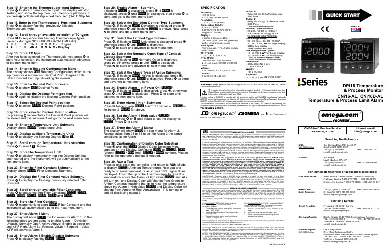
Step 29. Enable Alarm 1 SubmenuIf flashing ENBL is displayed, press a , if DSBL isdisplayed, press b until ENBL is displayed, then press d to store and go to the next menu item.Step 30. Select the Deviation Control Type Submenu Press d . If flashing _DEV Deviation is displayed press a ,otherwise press b until flashing _DEV is shown. Now press d to store and go to next menu item.Step 31. Select the Latched Type SubmenuPress d . If flashing UNLT Unlatched is displayed press a ,otherwise press b until UNLT is displayed.Press d to store and advance to next menu item.Step 32. Select the Normally Open Type of Contact Closure SubmenuPress d . If flashing N.o.Normally Open is displayed, press a , otherwise press b until N.o.is displayed. Press d to store and advance to next menu item.Step 33. Select the Above Type of Active Submenu Press d . If flashing ABoV Above is displayed, press a ,otherwise press b until ABoV is displayed. Press d to store and advance to next menu item.Step 34. Enable Alarm 1 at Power On (A.P.oN )Press d . If flashing ENBL is displayed, press a , otherwise press b until ENBL is displayed. Press d to store and advance to next menu item.Step 35. Enter Alarm 1 High SubmenuPress a twice to skip ALR.L Alarm 1 Low value. ALR.L is for below & ALR.H for above.Step 36. Set the Alarm 1 High value (ALR.H )Press d . Press b or c until value to set the display to 002.0. Press d to save.Step 37. Enter the Alarm 2 MenuThe display will show ALR2the top menu for Alarm 2.Repeat steps from 28 to 36 to set for Alarm 2 the same conditions as for Alarm 1.Step 38. Configuration of Display Color Selection Press a until the COLR Display Color Selection Menu appears on the Display. Configure COLR as N.CLR / GRN (green), 1.CLR / RED (red), 2.CLR / AMBR (amber). Please refer to the operator’s manual if needed.Step 39. Run a TestPress a until reset the controller and return to RUN Mode to display 075.0(Ambient Temperature). Now you are ready to observe temperature as it rises 10°F higher than displayed. Touch the tip of the Thermocouple to raise the temperature above the Alarm 2 High value 082.0, and AL2will turn on, and Display Color will change from Green to Amber. Continue touching the tip to raise the temperature above the Alarm 1 High value 087.0and Display Color will change from Amber to Red. Annunciator “1” is turning on and off displaying output 1.Step 10. Enter to the Thermocouple Input Submenu Press d to store Thermocouple Input. The display will stop flashing and show the top menu for Thermocouple types. If you press a controller will step to next menu item (Skip to Step 14). Step 11. Enter to the Thermocouple Type Input Submenu Press d to display flashing, previously selected Thermocouple type.Step 12. Scroll through available selection of TC types Press b to sequence thru flashing Thermocouple types,(select k -for type "K" CHROMEGA ®/ALOMEGA ®)J K T E N DIN J R S B C - TC types J k t E N dN J R S b C - DisplayStep 13. Store TC typeAfter you have selected the Thermocouple type press d to store your selection, the instrument automatically advances to the next menu item.Step 14. Enter to Reading Configuration MenuThe display shows RDG Reading Configuration, which is the top menu for 4 submenus: Decimal Point, Degree Units,Filter Constant and Input/Reading Submenus.Step 15. Enter to Decimal Point Submenu Press d to show DEC Decimal Point.Step 16. Display the Decimal Point positionPress d again to display the flashing Decimal Point position.Step 17. Select the Decimal Point position Press b to select FFF.F Decimal Point position.Step 18. Store selected Decimal Point positionBy pressing d momentarily the Decimal Point position will be stored and the instrument will go to the next menu item.Step 19. Enter to Temperature Unit Submenu Display shows TEMP Temperature Unit.Step 20. Display available Temperature Units Press d to display the flashing Degree °F or °C .Step 21. Scroll through Temperature Units selection Press b to select °F Degree.Step 22. Store the Temperature UnitPress d to display momentarily that the Degree Unit has been stored and the instrument will go automatically to the next menu item.Step 23. Enter the Filter Constant Submenu Display shows FLTR Filter Constant Submenu.Step 24. Display the Filter Constant value Submenu Press d to display the flashing, previously selected Filter Constant.Step 25. Scroll through available Filter Constants Press b to sequence thru Filter Constants 0001, 0002,0004, 0008, 0016, 0032, 0064and 0128.Step 26. Store the Filter ConstantPress d momentarily to store 0004Filter Constant and the instrument will automatically go to the next menu item.Step 27. Enter Alarm 1 MenuThe display will show ALR1the top menu for Alarm 1. In the following steps we are going to enable Alarm 1, Deviation,Unlatch, Normally Open, Active Above, Enable at power on and +2°F High Alarm i.e. Process Value > Setpoint 1 Value +2°F will activate Alarm 1.Step 28. Enter Alarm 1 Enable/Disable Submenu Press d to display flashing DSBL / ENBL .MQS3447/0206SPECIFICATIONAccuracy:+0.5°C temp;0.03% rdg. process typical Resolution:1°/0.1°; 10 µV process Temperature Stability:0.04°C/°C RTD;0.05°C/°C TC @ 25°C (77°F); 50 ppm/°C process Display:4-digits, 9-segments LED,10.2 mm (0.40") with red, green and amber programmable colors Input Types:Thermocouple, RTD, Analog Voltage and Current TC: (ITS90)J, K, T, E, R, S, B, C, N, L RTD: (ITS68)100/500/1000 ohm Pt sensor2-, 3-, or 4-wire; 0.00385 or 0.00392curve Voltage:0 to 100 mV, 0 to 1 V, 0 to 10 Vdc Current:0 to 20 mA (4 to 20 mA)Output 1†:Relay 250 Vac @ 3 A Resistive Load,SSR, Pulse Output 2†:Relay 250 Vac @ 3 A Resistive Load,SSR, Pulse †Only with -AL Limit Alarm optionOptions:Communication RS-232 / RS-485 or 10BaseT or Excitation:24 Vdc @ 25 mAExc. not available for Low Power OptionLine Voltage/Power:90 - 240 Vac ±10%,50 - 400 Hz*,or 110-375 Vdc, 4W for Single Display;5W for Dual Display* No CE compliance above 60 HzLow Voltage Power Option:12 - 36 Vdc, 3 W** for Single Display;20 - 36 Vdc, 4 W** for Dual Display**Units can be powered safely with 24 Vac but No Certification for CE/UL are claimed.Dimensions:48 H x 48 W x 127 D mm (1.89 x 1.89 x 5")Weight:159 g (0.35 lb)Approvals:UL, C-UL, CE per EN 61010-1:2001WARNING:These products are not designed for use in, and should not be used for, patient-connected applications.It is the policy of OMEGA to comply with all worldwide safety and EMC/EMI regulations that apply.OEMGA is constantly pursuing certification of its products to the European New Approach Directives.OMEGA will add the CE mark to every appropriate device upon certification.The information contained in this document is believed to be correct, but OMEGA Engineering,Inc.accepts no liability for any errors it contains, and reserves the right to alter specifications without notice.TRADEMARK NOTICE:®,®,, and are Trademarks ofOMEGA ENGINEERING, INC.®This Quick Start Reference provides informationon setting up your instrument for basic operation.The latest complete Communication and OperationalManual as well as free Software and ActiveX Controlsare available at /specs/iseries or onthe CD-ROM enclosed with your shipment. SAFETY CONSIDERATIONThe instrument is a panel mount device protected in accordance with EN61010-1:2001. Remember that the unit has no power-on switch. Building installation should include a switch or circuit-breaker that must be compliant to IEC 947-1 and 947-3.SAFETY:•Do not exceed voltage rating on the label located onthe top of the instrument housing.•Always disconnect power before changing signal andpower connections.•Do not use this instrument on a work bench withoutits case for safety reason.•Do not operate this instrument in flammable orexplosive atmospheres.•Do not expose this instrument to rain or moisture. EMC:•Whenever EMC is an issue, always use shielded cables.•Never run signal and power wires in the same conduit.•Use signal wire connections with twisted-pair cables.•Install Ferrite Bead(s) on signal wire close to theinstrument if EMC problems persist.Panel Mounting Instruction:ing the dimensions from the panel cutout diagramshown above, cut an opening in the panel.2.Insert the unit into the opening from the front of the panel,so the gasket seals between the bezel and the front of the panel.3.Slide the retainer over the rear of the case and tightenagainst the backside of the mounting panel.。
Quick A2L 用户手册

Quick A2L
© 2010 – 2013, Quick A2L Project. All rights reserved.
19
Quick A2L
© 2010 – 2013, Quick A2L Project. All rights reserved.
5
Quick A2L 用户手册
导入A2L/Hex文件
选择a2l/hex文件后,导入开始,导入过程将提示导入进度
A2l/hex文件导入成功后,在选中的文件夹下将生成一个新的文件节点
Quick A2L 用户手册
Quick A2L 用户手册
Quick A2L
© 2010 – 2013, Quick A2L Project. All rights reserved.
1
Quick A2L 用户手册
功能特点
快速解析 A2L/Hex/S19 文件 对EMS/TCU功能框图文档(PDF,Word等)进行屏幕取词,快速获取标定量数据 直观显示同一标定量在不同标定数据中的差异 支持对标定量,系统常数和测量变量名称和解释的模糊查询 BOSCH EMS DFPM/DSM诊断故障码列表
启动后直接显示取词面板:
选中该选项后,程序启动时将自动显示取词面板
导入数据时检查EPROM是否匹配:
如A2L中定义了EPROM信息,则在数据解析时刻根据EPROM定义判断A2L和 Hex文件是否匹配,推荐勾选该选项
取词面板自动隐藏
勾选后取词面板可按定义的延时自动关闭
取词模式
鼠标屏幕取词: 勾选后可通过鼠标悬停获得屏幕上显示的文本 剪贴板取词: 勾选后通过监控剪贴板内容变化(Ctrl+C)获取文本
Quick Start Guide 快速入门指南说明书

40mm screws
3mm nuts
3. Propellers
The wings silver spinners spin clockwise and the pylons black spinners spin counter-clockwise. a) Unscrew the spinner and place the 10x5 props on the main wing motors, and the 10x5R on the pylon motors. b) Tighten the spinner by holding the motor still and spinning the spinner into place. Tighten firmly with fingers.
safety switch
c) (Ai Only) Ensure that the craft has a GPS signal by checking for a blue light inside the compass unit. d) Arm the motors by holding the throttle down and right.
*Always fly at locations that are clear of building and other obstacles. *DO NOT fly above or near large crowds. *Avoid flying at altitudes above 400 ft. *Be very careful when flying 19,600 ft. or more above sea level. *Fly in moderate weather conditions with temperatures between 32° F to 104° F.
Quick Connect Basic Installation and user 说明书
Easy to install Adaptable for changesSeveral labs in one 100 % safeEasy to installPre-install and decide laterServeral labs in one100 % safeThis is an installations guide for Quick Connect Basic.Quick Connect is the new, innovative and flexible lab solution.Quick Connect is based on the concept plug and play and easy to install. BROEN-LAB has furthermore made a drilling template which makes it easi-er to drill the mounting holes for the installation of Quick Connect. For futher information see page 23.Before installation please read the chapter, Purity on page 22.PANEL MOUNTEDBUILT-IN MOUNTEDBENCH MOUNTEDEXPOSED PIPECONCEALED PIPESUSPENDED MOUNTEDDISC MOUNTEDTable of Contents 4-5 Quick Connect Basicmounted 6-7 Panelmounted 8-9 Built-inBench mounted 10-11 Exposed pipe mounted 12-13 Concealed pipe mounted 14-15 Suspended mounted 16-17 Disc mounted 18-19 Changing media type 20-21 Purity 2.0, 4.0, 5.0 22 Drilling template 23 Trouble shooting guide 24-25 Accessories and datasheets 26-27Temperature range: 0-90o CMax. working pressure: 16 bar/232 psi Inlet: BROEN-LAB UniFlex TM Materials with media contact Metals: BrassNitrile (NBR) VITON (FKM) EPDM Panel thickness up to 26 mmAssemblyCartrid g eO-ringM4 (x2) screwFront partFront ringRear PartNutFemale BROEN-LABUniFlex TMSTEP 1STEP 2STEP 3MountingDatasheetTool: A wrench key+1All measurements are in mmTemperature range: 0-90o CMax. working pressure: 16 bar/232 psiPanel thickness 1-6 mm AssemblyCover ringO-ringFront partFront ringGASInlet: Femal e BROEN-LAB UniFlex TM Materials with media contactMetals: Brass Nitrile (NBR) VITON (FKM) EPDMg eDatasheetMountingTool: Allen key 3 mm for (2x) M5x8 screws Allen key 2,5 mm for (2x) M4 screws2,5 mm 3 mmNice to know!Built-in is delivered assembled and has to be disassembled before mounting - Follow the mounting backwardsPlace the rear part from theDepending on the wall thick-Place the locking plate Place the front part over the All measurements are in mmMount with (2x) M5x8 mmTemperature range: 0-90o CMax. working pressure: 16 bar/232 psiInlet: BROEN-LAB UniFlex TM Panel thickness 30-90 mm AssemblyCoverRear PartM3x12 ScrewInlet pipeUniFlex Connection (Need to be pre-mounted)Materials with media contactMetals: Brass Nitrile (NBR) VITON (FKM) EPDMDatasheetSTEP 1STEP 2STEP 3MountingTool: A Phillips screwdriver, size 21234All measurements are in mmTemperature range: 0-90o CMax. working pressure: 16 bar/232 psi Inlet: BROEN-LAB UniFlex TM Assemblyg eM4 (x2) screwFront partFront ringRear PartFemale BROEN-LAB UniFlex compression Materials with media contactMetals: Brass Nitrile (NBR) VITON (FKM) EPDMOnly for plates where threads can be drilled.MountingTool: Allen key for M3x25 (x4) screw s A llen key for M4 (x2) screwsFront: Use (4x) M3x25 mounting screws ( included) Rear: Use (4x) M4x25 screws (included)mm STEP 3STEP 4STEP 6STEP 7STEP 8STEP 1Front:Mounting with (4x) M3 mm screws Rear:Mounting with (4x) M4 mm screwsPush the cartrigde into therear partTighten the (2x) M4 screwsPush the front ring with light forceinto placeDraw a centerline and place the sticker with the drilling template e STEP 5Slide the black cover onDrill after the green marks on thestickerNice to know!Exposed isdelivered assembled and has to bedisassembled before mounting - Follow the mounting backwards3 mmCatridgeFemaleBROEN-LAB UniFlex TMFront partFront ringRear PartTemperature range: 0-90o CMax. working pressure: 16 bar/232 psiInlet: BROEN-LAB UniFlex TM AssemblyMaterials with media contactMetals: Brass Nitrile (NBR) VITON (FKM) EPDMFor furniture without space fortightening behind the wallMountingDatasheet6STEP 8Mounting with (4x) M3x25 mm screws Push the catridge into the rear partSlide the black cover on Push the front ring with light forceinto placeTool: Allen key for (4x) M3x25 screwsA llen key for (2x) M4 screws (front mounting and media changing- includedSTEP 3STEP 4STEP 5mmNice to know!Concealed isdelivered assembledand has to bedisassembled beforemounting - Follow themounting backwardsAll measurements are in mmSTEP 2STEP 1Drill after the green and redmarks on the stickerTemperature range: 0-90o CMax. working pressure: 16 bar/232 psiPanel thickness 30-90 mm AssemblyCoverRear PartM3x12 ScrewMounting plateLocking pinsInlet pipeHoseUniFlex ConnectionInlet: BROEN-LAB UniFlex TM Materials with media contactMetals: Brass Nitrile (NBR) VITON (FKM) EPDMMountingDatasheetSTEP 2STEP 3Tool: A Phillips screwdriver , size 21234mmSTEP 1Inlet: BROEN-LAB UniFlex TM /For porous wallsTemperature range: 0-90o CAssemblyCatridge Cover, Long O-ringFemaleTMM4 (x2) screw Front partFront ring(4x) M3x25Mounting discMaterials with media contactMetals: Brass Nitrile (NBR) VITON (FKM) EPDMFront mounting in soft material where threads not can be drilledDatasheetSTEP 3STEP 4STEP 6STEP 7STEP 8STEP 1Mount the mounting disc with screws - not included Moun t the rear part with the (4x) M3 x25 mm screwsTighten the (2x) M4 mm screwsPush the front ring with light forceinto placeDraw a centerline and place the sticker with the drilling template eSTEP 5Slide the black cover onDrill after the blue and red markson the sticker All measurements are in mmWith Quick Connect is it possible to make last minute changes.It is important only to change between the gases within the same category.There are 3 categories: Non-burning gases, burning gases and water.Types of mediaThe changeable mediaNon-burning gases Burning gases WaterNot possiblePossibleMedia changingSTEP 1STEP 2Move the front ring i.e. CA by pulling it out with lightforceLoosen the (2x) M4 mm screws - only a little bit.12Push the front ring with light force into placeTighten the (2x) M4 mm screws12Tool: 3 mmSTEP 5STEP 62.0, 4.0 and 5.0 indicate the purity of the gases.2.04.05.099 %99,99 %99,999 %Changes or modifications are not allowed to be made to the equipment without prior approval from BROEN -LAB .Improper handling or use can involve risks for the user and other persons as well as damage of the equipment.The equipment can only be used for the gas type it was manufactured and labelled for. Change can be made prior to start of use, provided that the new media is listed in the data sheet, or BROEN -LAB has approved the new media.Observe the maximum pressure & temperature ranges.The equipment cannot be used for gases in the liquid phase.The equipment must not be exposed to impact, vibrations or other mechanical forces that can damage the equipment. The equipment is designed for use in laboratories. The equipment is not designed for installing where there is a possibility of exposure to aggressive media.By installation avoid oil and grease contamination (Fire or explosion hazard). It is recommended to use a proper leak detection fluid or similar to check for leak when installing and using the Quick Connect.These valves do not contain a relief valve. In case of failure, the outlet pressure may rise above the adjusted value. Anyequipment connected to the equipment Purity 5.0 in useWhen changing the outletTo maintain a purity of 5.0, BROEN-LAB recommends to purge the system in 30 sec. before usage, when you change the outlet.Safety instructionsHandling of technical gases requires knowledge of the subject, operation instructions and special safety measures. Always check national and local laws, regulations and procedures regarding the installation and use of this type of equipment., ERROR CAUSE ACTIONERROR CAUSE ACTIONThe outlet is leaking There are leaksinside the outlet Replace the o utlet with a new oneAccessorie s Datasheet s97Pressure regulatorDatasheet sAccessorie sBROEN-LAB Ltd.BROEN-LAB Singapore Pte. Ltd.BROEN-LAB A/S BROEN-LAB GmbH BROEN-LAB Sverige AB broen-lab .comINTERNATIONAL OFFICESUnit 9 Navigation Point, Golds Hill Way Tipton • West Midlands DY4 OPY • U.K.Tel. +44 121 522 4515 • Fax +44 121 522 4535E-mail:*****************10 Bukit Batok Crescent #10-02 • The Spire • Singapore 658079Tel: +65 6298 0662 • Fax: +65 6298 0468 E-mail:*****************HEAD OFFICE Drejervænget 2 • DK-5610 AssensTel. +45 6376 6376 • Fax +45 6471 2476 E-mail:*****************Tel. +45 6376 6376 • Fax +45 6471 2476 E-mail:*****************Tel. +45 6376 6376 • Fax +45 6471 2476 E-mail:*****************BROEN-LAB A/S ISO 9001 certificationIn September 1991 BROEN-LAB A/S was certified according to ISO 9001 as one of the first Danishcompanies. The certification was carried out by Bureau Veritas, Denmark, for our Danish site in Assens.The quality management system of BROEN-LAB A/S now complies with detailed specifications laid down by the internationally acknowledged EN ISO 9001:2008. This certification will further contribute to reputationfor quality and reliability of BROEN-LAB A/S.94G0243 UK 109/12-2020。
QuickCap NX商品说明书
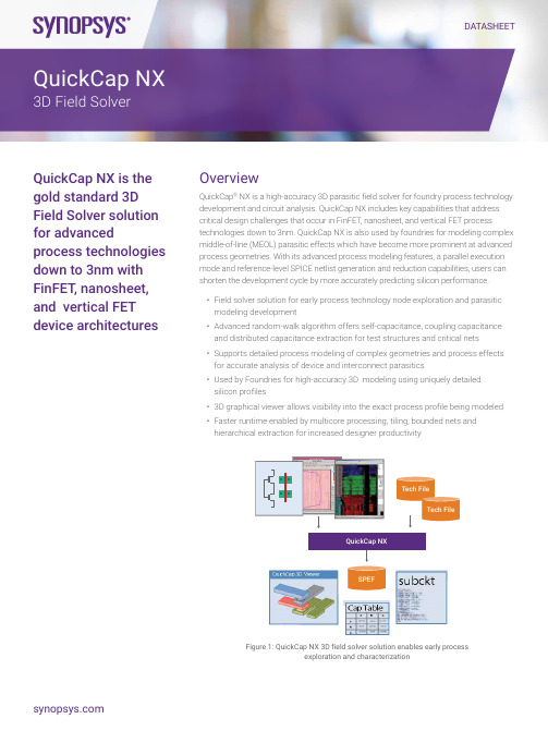
DATASHEET Overview QuickCap ® NX is a high-accuracy 3D parasitic field solver for foundry process technology development and circuit analysis. QuickCap NX includes key capabilities that address critical design challenges that occur in FinFET, nanosheet, and vertical FET process technologies down to 3nm. QuickCap NX is also used by foundries for modeling complex middle-of-line (MEOL) parasitic effects which have become more prominent at advanced process geometries. With its advanced process modeling features, a parallel execution mode and reference-level SPICE netlist generation and reduction capabilities, users can shorten the development cycle by more accurately predicting silicon performance.• Field solver solution for early process technology node exploration and parasitic modeling development • Advanced random-walk algorithm offers self-capacitance, coupling capacitance and distributed capacitance extraction for test structures and critical nets • Supports detailed process modeling of complex geometries and process effects for accurate analysis of device and interconnect parasitics • Used by Foundries for high-accuracy 3D modeling using uniquely detailed silicon profiles • 3D graphical viewer allows visibility into the exact process profile being modeled • Faster runtime enabled by multicore processing, tiling, bounded nets andhierarchical extraction for increased designer productivitySPEFQuickCap NX Tech File Tech File Figure 1: QuickCap NX 3D field solver solution enables early process exploration and characterizationQuickCap NX is thegold standard 3DField Solver solutionfor advancedprocess technologiesdown to 3nm withFinFET , nanosheet,and vertical FETdevice architecturesQuickCap NX 3D Field SolverAs geometries shrink and clock frequencies increase, designers need more accurate parasitic values to reduce risk of design failure. The growing need for more accuracy makes it necessary to account for precise fringing electrostatic fields and process effects in test structures and analyzing critical cells, blocks, and nets. QuickCap NX provides robust, consistent, and accurate 3D capacitance extraction with capacity to handle moderately sized blocks or long critical nets. QuickCap NX’s proven modeling capabilities allow users to perform accurate noise and timing analysis for robust design development and improved silicon success.Advanced 3D Modeling and Process DevelopmentQuickCap NX includes the ability to create 3-D physical models which precisely match advanced process technology profiles and account for new effects like, diamond EPI growth, EPI and trench contact parasitics, and non-linear gate resistance. The unique capability allows foundries and early technology adopters to engage earlier to explore device parasitic capacitance effects in new technology nodes and accelerate the development schedules.An exclusive technology file encryption feature provides foundries with a secure method of sharing critical process information with their customers, allowing them to enhance the accuracy of their analysis and speedup the migration to new nodes. In addition, multicore capabilities and hierarchical processing significantly improve runtime, and a powerful 3D graphics viewer simplifies the development and debug of new complex circuit structures and technology files. As a result, QuickCap NX is broadly used in process studies, characterization and correlation across several generations of process nodes, and to support highly accurate device-level SPICE simulations.Modeling down to 3nmFinFET, nanosheet, and vertical FET process technologies achieve better control over the source-drain channel because the gate encloses the channel on three or more sides, resulting in higher mobility, greater drive strength, lower switching currents, and lower leakage currents. This 3D architecture also introduces more complex geometries and many new capacitive elements that require highly accurate modeling. QuickCap NX’s geometry pre-processing engine provides a highly accurate physical profile of the FinFET, nanosheet, or vertical FET for modeling, and its graphical viewer allows users to see exactly how the device will be modeled. Finally, the core 3-D field-solver engine of QuickCap NX accurately extracts the capacitance values from the model. Combined, thesecapabilities allow QuickCap NX to provide the necessary precision to model devices down to 3nm and as a result it has been adopted by leading foundries for this purpose.Powerful Geometry Processing EngineThe geometry pre-processor capability “gds2cap” translates the 2D layout data into a 3D representation and reduced SPICE netlist with resistance and capacitance. The gds2cap capability includes a flexible polygon-processing engine that handles multipleconformal dielectrics, non-Manhattan geometries, non-planar metals, metal fill, process effects (OPC, CMP , Trapezoidal wire), device recognition, resistance extraction and exclusion of device capacitances. QuickCap NX takes the 3D representation and the netlist output from the gds2cap interface, produces an output file containing self and coupling- capacitance values and replaces thecapacitance values in the netlist with accurately computed values from QuickCap NX.Detailed Silicon Profile based 3D Modeling Accurate Middle-of-line Parasitic Extraction Gate Fin Source DrainM0V0M0V0 Figure 2: QuickCap NX is used by foundries for FinFET modeling down to 5nmAs drawn OPC width = f(w,s)Sidewall shape = f(z)Width expanded = f (layer)Sidewall OPC = F(w,s,z)Thickness = f (local density)Figure 3: QuickCap NX provides precise physical models of process effectsProven Parasitic Capacitance ExtractionQuickCap NX has demonstrated close correlation to silicon measurements at various process nodes. Its advanced modeling,including modeling of optical, copper, Ruthenium, and new conducting material effects as well as in-die process variations, enable increased accuracy. The validation of QuickCap NX’s silicon accuracy by foundries has led to its wide use in early process technology development and device characterization.For advanced users, QuickCap NX also provides a dial-in accuracy and error- bounds reporting on each net, providing the flexibility and control for their target application needs.Handling Large LayoutsQuickCap NX provides multiple techniques to enable critical net analysis in designs too large to fit in memory. Runtime or memory use can be reduced by using tiling, bounded nets, hierarchical processing, multicore processing or a combination of these techniques.Key Features Summary• 3D modeling of FinFET, nanosheet, and vertical FET process technologies down to 3nm• Accurate extraction of self-coupling and distributed capacitance• Robust and accurate handling of complex geometries including non-Manhattan structures, conformal dielectrics,and floating metal• Advanced process effects for in-dieprocess variation, optical, copper, Ruthenium, and new conducting material effects• 3D graphics viewer• Dial-in accuracy and error bounds reporting for each net• Low memory usage independent of accuracy• Runtime independent of net length• Exclusion of device capacitance and optional inclusion of device fringe capacitance• Parasitic reduction• Flat and hierarchical processing• Tile or bounded net analysis• Multicore processing• Technology file encryptionInput• GDSII or scripted text• Output• Back annotated SPICE netlist• Capacitance summary in a matrix• Platform/OS• 64 bit Solaris and LinuxFor more information about Synopsys products, support services or training, visit us on the web at: , contact your local sales representative or call 650.584.5000.©2018 Synopsys, Inc. All rights reserved. Synopsys is a trademark of Synopsys, Inc. in the United States and other countries. A list of Synopsys trademarks isavailable at /copyright.html . All other names mentioned herein are trademarks or registered trademarks of their respective owners.。
BESV PS1 Quick Assembly Guide

快速组装说明Quick Assembly GuideBESV PS1V. 1.0, Jan. 2015Contents1. 零件说明 (2)1.1 车体Bike (2)1.2 配件包与零件 (2)2. 组装流程 (3)2.1 前轮 (3)2.2 竖管延长管 (5)2.3 车手把 (6)2.4 前土除与前灯 (7)2.5 踏板 (10)2.6 仪表 (HMI, Human Machine Interface) (11)2.7 电池 (13)2.8 座垫座杆组 (14)2.9 后灯 (15)3 检查 (16)1.零件说明1.1车体Bike(1)车体组件(2)配件包(3)座垫座杆组(4)前轮1.2配件包与零件配件包内含以下配件:(1)说明书(2)充电器(3)仪表 (HMI, Human Machine Interface)(4)前灯(5)踏板(6)后灯(7)前轮快拆(8)前土除脚(9)竖管延长管2.组装流程2.1前轮2.1.1取出车子,解下前轮。
2.1.2将前轮安装至前叉钩爪内。
注意碟盘需位在卡钳的正中央。
2.1.3安装快拆转开快拆螺帽,从车子左侧组装快拆。
注意弹簧方向为内小外大。
注意,快拆把手位在车子左侧。
2.1.4锁紧快拆螺帽先旋紧螺帽, 再旋松约1/4圈。
将快拆把手往上压紧,与前叉平行。
旋转前轮,确认转动顺畅。
2.2 竖管延长管2.2.1 将延长管(a)插入前叉(b) 。
2.2.2 调整延长管方向延长管龙头朝向正前方,束子(d)的缺口朝向正后方。
2.2.3 锁紧束子(d)两侧的螺丝(c) 。
螺丝锁附扭力值:7N-m 。
abdc2.3 车手把2.3.1 卸下龙头固定环(e)2.3.2 放置车手把将车手把置中装入龙头,再锁上龙头固定环,但勿锁紧。
参考手把上的标线,将车手把水平垂直置中于龙头固定环。
2.3.3 锁紧龙头固定环先锁上方的两颗螺丝直到固定环与龙头之间间隙约0.5mm 时,再锁下方两颗螺丝。
洛雷克安全摄像头系统操作指南说明书

E n h a n c e dF u nc t i o n a l t yF R E E D Y N A M IC D N S S E R V ICESETTING UP YOUR DIGTIAL VIDEO RECORDER (DVR)This set-up guide assumes you are connecting cameras (not included with this system) to the Lorex DVR. Consult your DVR’s owners manual for alternative DVR connectionand/or information to install a hard disk drive (HDD).Connect the cameras (not supplied) to the CH , CH2, CH3, CH4 Video Inputs (BNC Inputs)2Connect the IR Sensor - To Operate Your DVR Remote ControlYour manual to learn how to record, playback, use the search features and all other features available with this sys-tem. Monitoring.NOT INCLUDED - MONITOR, CAMERAS & BROADBAND ROUTER1 - L224 Series DVR 1 - Power Cord1 - AC Power Adapter1 - Owners Manual & Warranty 1 - Need Help Insert 1 - Remote Control 1 - IR Sensor4 - Mounting Screws1 - Quick Installation Guide 1 - Software Application CD 1 - External I/O Port Pin ConnectorPACkAGE CONTENTSThis DVR unit comes with an IR Sensor on a wire that you connect from the back of the unit and place in the front panel of the DVR.BACK OF THE DVRBACK OF THE DVRFRONT OF THE DVRPOWER CORDIR SensorFor Monitor connections, please refer to the owners manualLAN (LOCAL AREA NETWORK)BACK OF THE DVRACCL224VGA - Optional VGA Converter Accessory• Allows the L224 Series DVR to be connected to a PC monitor • Converts the signal to VGAF R E E D Y N A M ICD N S SE R V IC EDVR CASE INSIDE OF THE DVRSCREWSScrew the HDD onto the HDD bracket2Unscrew the HDD bracket34Screw theHDD bracketback to theDVR baseConnect the HDD to the power connector and IDE Bus (makesure to align the HDD precisely for PIN connection).56Close the upper case of the DVR and fasten all thescrews you loosened in the Section .Open the upper cover of the DVRLoosen the two screens respectively on the two sides of theupper cover. Loosen the four screws on the back side ofthe upper cover.INSIDE OF THE DVRINSIDE OF THE DVRSCREWSBACK OF THE DVRSIDE OF THE DVRSCREWSCONNECTORSCREWSBACK OF THE DVRSIDE OF THE DVRINSIDE OF THE DVRINDICATES WHERE THE SCREWS ARE PLACEDNOTE: Please make sure to place the HDD connector facing the back panel of the DVRE n h a n c e dF u nc t i o n a l t yF R E E D Y N A M IC D N S S E R V ICESETTING UP LOCAL SECURITY MONITORING2Press the Search button to obtain the DVRs MAC & IP registration for DDNSNote: Search only works if the DVR is on the local network with your PC. It will not work otherwise.IPADDRESS :(record the period. It is part of the IP Address)•••:::::(needed to register for DDNS)MACADDRESS :instructions2345T I P : A S P A R T O F T H E D V R S O F T WA R E A P P L I C A T I O N I N S T A L L A T I O N , Y O U M A Y C H O O S E T O I N S T A L L T H E J A V A A PP L I C A T I O N P R O G R A M F O R R E M O T E S E C UR I T Y M O N I T O R I N GF R E E D Y N A M ICD N S SE R V IC E3On the Login Screen, enter your User Name (defaultadmin) and Password (default admin) and the pressConnect buttonUpdated to match the IPof the DVR when selectedOK in step 2.4You can now view theLIVE VIDEO locallyYour DVR is now ready for Local Security Monitoring. Foradvanced settings, refer to your owner’s manual of thisproduct. Refer to Step 4 for Setting Up Remote SecurityMonitoring.E n h a n c e dF u n ct i o nalt yF R E E D Y N A M ICD N S SE R V IC E SETTING UP REMOTE SECURITY MONITORINGComplete New Account Information2Click CREATE ACCOUNT option3Open your Web BrowserEnter Port forwarding your router and creation of a DDNS account with Lorex is required in order for you to have Remote Internet Access.Create Account1. FOR PRODUCT LICENSE select the L224 Series option from the dropdown menu.2. FOR PRODUCT CODE enter the DVR’s MAC address (recorded in step3, section 2).3. FOR URL REQUEST enter a unique URL name (eg. Johndoe). Note: AnURL name should not be more than 15 characters.1234Create the NEW ACCOUNT Link5An Automated Registration Confirmation Emailwill be sent to your email. Print and Save thisRegistration Confirmation.Service Provider: Domain name: User name: John DoePassword: enter password from emailF R E E D Y N A M ICD N SS E R V IC EPort Forward your Router76Select SETTINGS from the VIDEO WEBSERVER applicationPort forwarding your router and creation of a DDNS account with Lorex is required in order for you to have Remote Internet Access.In the SYSTEM SETTINGS Screen select DDNS. Fillin the blanks with the information you received partof your Automated Registration Confirmation email( Step 4, Section 5) and press APPLYEnter information from yourAutomated RegistrationConfirmation EmailPort Forward your Router FIRST before proceeding withthe Set-up (you must Port Forward Port 80).All routers are different. To Port Forward your Router:Refer to your Router’s manual for specific instructionson port forwarding (or)Check the Router configuration guide support documentin the consumer guide section on our website http:///uploads/PortForward_Guide.pdfE n h a n c e dF u nc t i o n a l t yF R E E D Y N A M IC D N S S E R V ICESETTING UP REMOTE SECURITY MONITORING - CONTINUEDPort forwarding your router and creation of a DDNS account with Lorex is required in order for you to have Remote Internet Access.。
Festo CPX-FB38 快速入门指南说明书
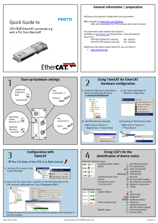
Documentation with detailed descriptions available at (Automation -> Documentation) Search for:
Right click on “Device 1” -> Append box -> Choose Festo
4. Scanning for field device online
Right click on “Device 1” -> “Scan Boxes”
3
Configuration with TwinCAT
follow steps: 1. Select the PLC object (Type : Bool) and press “Linked to..” 2. Activate the field “All Types” in the Pop-Up window 3. Select now the Byte of the module and press Button “OK”.
The default setup defines all output signals to the OFF state during one of the modes
An optional channel based setup can be made:
Value to OFF (default) Value to ON Hold Last State
Digital and valve modules (I/O, MPA, Pneu. Interface)
BESV LX1 快速装配指南 V. 1.0,2015年1月说明书

Quick Assembly GuideBESV LX1Contents1. What’s in the Box (2)1.1 Main Box Contents (2)1.2 Accessory Box Contents (2)2. Assembly Procedures (3)2.1 Front Wheel (3)2.2 Front Fender and Reflector (5)2.3 Pedal (6)2.4 Battery (7)2.5 Saddle & Seat Post (8)2.6 Rear Light (9)3 Checklist (10)1. What’s in the Box 1.1 Main Box Contents1. Main Bike Assembly2. Accessory Box3. Saddle/Seat Post Set4. Front Wheel5. Front Fender1.2 Accessory Box Contents1. Product Documentation2. Charger3. Pedals4. Rear Light & Reflector5. Quick Release (QR) for the Front Wheel6. Key7. Front reflector and screw sets for front fender352.Assembly Procedures2.1Front Wheel2.1.1Unpack the front wheel and themain bike assembly.2.1.2Insert the wheel into the fork end.Attention: The disk should beplaced between the brake pads.2.1.3Set the quick release (QR)Unscrew the nut and spring from the QR andinsert the QR stem from the left side of thebike.Attention: The quick release handle shouldbe on the left side of bike.2.1.4Tighten the nutPlace the spring back in the QR stem andtighten the nut until you encounter resistance.Then loosen 1/4 turn。
CBS双能DR型X射线通道式安检机软件说明书提交模板
CBS双能DR型X射线通道式安检机软件说明书提交模板1. 软件说明书概述CBS双能DR型X射线通道式安检机软件说明书旨在向用户提供关于软件的详细信息和操作指导。
本文档主要包括软件概述、安装指南、使用说明、故障排除和维护等内容,以便用户能够正确安装、配置和使用该软件。
2. 软件概述2.1 功能介绍CBS双能DR型X射线通道式安检机软件是一款专业的安全监测软件,通过分析X射线图像,实现对入侵物品和危险品的快速识别和报警。
其主要功能包括:- 高清影像显示:能够显示清晰、细致的X射线图像,方便用户观察和分析;- 自动辐射剂量控制:智能控制辐射剂量,避免对人体健康造成伤害;- 图像增强和滤波:通过图像处理算法,增强图像的对比度和细节,以提高识别准确性;- 应用软件更新:支持在线更新软件版本,确保软件始终处于最新状态。
2.2 硬件环境要求为了保证软件的正常运行,需满足以下硬件环境要求:- 操作系统:支持Windows 7及以上版本;- 处理器:Intel Core i5 以上;- 内存:8GB以上;- 存储空间:100GB以上。
3. 安装指南3.1 前期准备在安装软件之前,请确保已经进行了以下准备工作:- 检查操作系统是否满足硬件环境要求;- 确保计算机已连接到正常稳定的电源;- 检查硬盘空间是否足够。
3.2 安装步骤以下是CBS双能DR型X射线通道式安检机软件的安装步骤:1. 双击安装程序,启动安装向导;2. 按照向导的指示,选择安装路径和其他自定义配置;3. 单击“下一步”继续,等待安装程序完成;4. 安装完成后,单击“完成”退出安装向导。
4. 使用说明4.1 软件启动与登录打开软件后,根据以下步骤进行登录:1. 输入用户名和密码;2. 单击“登录”按钮。
4.2 软件界面介绍在成功登录后,进入软件的主界面,界面包括以下几个部分:- 菜单栏:提供软件的各项功能和设置选项;- 工具栏:显示常用的操作按钮,方便用户进行操作;- 图像显示区域:显示X射线图像,支持放大、缩小等操作;- 结果显示区域:显示检测结果和警报信息;- 参数设置区域:用于设置软件的各项参数。
3CX 快速参考指南说明书

A. Loader arm – raise B. Loader arm – lower
C. Loader arm – roll forward D. Loader arm – roll back
A. Dipper in B. Dipper out
Stabilizer Controls Manual A. Raise stabilizer B. Lower stabilizer C. Raise stabilizer D. Lower stabilizer
Excavator End Controls Manual – SAE Plus (‘+’) Pattern
A. Left hand lever B. Right hand lever
A. Boom raise B. Boom lower
A. Slew left B. Slew right
A. 45° Transmission Mode
3CX
QUICK REFERENCE GUIDE
This Quick Reference Guide DOES NOT replace the Operators Manual. You MUST read ALL the disclaimers and safety and other instructions in the Operators Manual before initially operating this product. Accordingly, no legal claims can be entertained based on the data, illustrations or descriptions in this Quick Reference Guide.
Ernitec Hawk SX camera Quick Guide
Ernitec Hawk SX camera Quick GuideThe quick guide is for quick installing and connecting the Ernitec Hawk SX Bullet Camera. For details, please refer to the camera ’s User Manual.Cable DefinitionIP Camera InstallationPlease follow the instructions below to complete IP Camera installation.Power up the CameraTo power up the IP Camera, please plug the camera ’s DC 12V/ AC 24V cable into the power outlet. Alternatively, connect the Ethernet cable to the camera ’s PoE port and plug the other end of the cable into a PoE switch.NOTE: If using PoE, make sure Power Sourcing Equipment (PSE) is in use in the network.Ethernet Cable ConnectionConnect one end of the CAT5 Ethernet cable to the RJ-45 connector of the IP Camera, and the other end of the cable to the network switch or PC.NOTE: In some cases, you may need to use an Ethernet crossover cable when connecting the IP Camera directly to the PC.NOTE: Check the status of the link indicator and activity indicator LEDs; if the LEDs are unlit, please checkLAN connection.IP Camera, please ensure downloading the ActiveX control is allowed by either changing the ActiveX controls and plug-ins or setting Internet ’s security level to default. For further details, please refer to the IP Camera ’s user manual.IP Camera LoginThe IP Camera ’s default IP address is: 192.168.0.250. Therefore, to access the IP Camera for the first time, set the PC ’s IP address as: 192.168.0.XXX; for example: IP Address: 192.168.0.100 Subnet Mask: 255.255.255.0Login ID & Password∙ Key in the IP Camera ’s IP address in the URL bar of the Web browser window and press “Enter.”∙ Enter the default user name (Admin ) and password (1234) in the prompt request dialogue. Note that user name is case sensitive.Install the ActiveX Control∙ After connecting to the IP Camera, the request for installing the ActiveX control will appear just below the URL bar. ∙ Right Click on the information bar, and press “Install ActiveX Control …” to permit ActiveX control installation.∙ In the pop-up security warning window, click “Install ” to start downloading DC Viewer software on the PC. ∙ Press “Finish ” after DC Viewer installation is complete.A U T O I R I S1234I /OL I N E I N M I C I NV1.5.09.12Browser-based ViewerThe main page of the IP Camera user interface is shown as the figure below. Please note that function buttons will vary depending on the camera model.Ernitec Hawk SX CameraQuick Guide。
- 1、下载文档前请自行甄别文档内容的完整性,平台不提供额外的编辑、内容补充、找答案等附加服务。
- 2、"仅部分预览"的文档,不可在线预览部分如存在完整性等问题,可反馈申请退款(可完整预览的文档不适用该条件!)。
- 3、如文档侵犯您的权益,请联系客服反馈,我们会尽快为您处理(人工客服工作时间:9:00-18:30)。
4. Open now your current project and copy the CPX configuration from your opened project inside the current one via drop & drag.
Short Summary:
பைடு நூலகம்
3. Importing the L5K file (File -> Open -> “...”.L5K
1. Dynamic addressing BOOTP/DHCP 2. Manual IP addressing
M12 D-coded D Ethernet connection
See manual: Chapter 1.2
See manual: Chapter 3.1
3
Using RSLogix 5000 for EtherNet/IP
Additional information about EtherNet/IP can be found on: •
1
1
Default
Remote I/O
Start-up up hardware settings
Additional Diagnostic Bits: - deactivated
Note: The internal CPX mapping cannot be changed by the configuration tools! In addition read appendix B of the CPX-FB36 manual
Note: If you want that the settings available after power off/on then you must in the “Relation List” press “Disable BOOTP/DHCP”
The benefits are: • Correct data format and I/O size at Generic Ethernet Device • Integration of all CPX start up parameters at the Controller-Tags
Tip
General information / preparation
Setting up the network configuration and parameters
Quick Guide for
CPX-FB36 EtherNet/IP with Allen Bradley controllers
I/O Diagnostic Bits (Deactivated by default)
1 2 3 4
Technologies modules (e.g. CPI Interface, CPX-FEC)
2. Configure the network. 3. - In the window “Request History” you find all devices in the network - Via the MAC ID the Festo EtherNet/IP can be identified (MAC ID also on label) - Mark the node and press button “Add to relation list”
2. Use the profile “Generic Ethernet Device” within RSLogix From RSLogix Rev20 You can also use the EDS EDS-File for configuration. In this case “CPX “CPX-FB36” Can be selected instead Of “Generic Ethernet Module”
Use CPX-MMI or FMT (Festo Maintenance Tool) with Ethernet connection to change parameters.
In “ System parameter “ choose for the Start-UP parameter the option -> “Saved parameter”
Tip
Input data order Analogue modules, each channel 16 Bit
CPX-FB36 I/O mapping
Output data order I/O Diagnostic Bits (Deactivated by default) Analogue modules, each channel 16 Bit Technologies modules (e.g. CPI Interface, CPX-FEC) Digital and valve modules (I/O, MPA, Pneu. Interface)
Terminal with only outputs: Activate Diagnose Interface (+ 2 Byte I/O) or the Statusbits (+ 2 Bytes I)
Terminal with only inputs: Activate Diagnose Interface (+ 2 ByteI/O)
When FEC or CEC is integrated
2
Using RSLogix 5000 for EtherNet/IP
Operating mode:
1. Add the CPX CPX-FB36 as new module above the Ethernet/IP bridge
Status LEDs (see 4)
EDS available at /sp/cpx EDS allows basic configuration in the host-system Documentations with detailed descriptions are available at the Festo Support Portal. Go to /sp/cpx Search for: CPX-FB36 (manual): CPX-SYS (CPX-System System manual): EN – 8024075 EN – 526446
On click Controller-Tags ->
Input data Output data
data format: SINT Note: The configuration data “Festo:C” can be used for setting CPXParameters
Festo AG & Co KG
3. Enter the following in the window “Module Properties” - Name for field bus node - Instances for inputs (101 101) and outputs (100) with according sizes - Instance for Configuration Assembly ( (102) ) with size: 0 - Data Format: SINT - Insert IP address
Mapping in RSLogix 5000
Tip
• •
Changing parameters of the CPX without L5K option
After the right I/O mapping (see Point 3) you’ll find the process data inside the RSLogix project at the Controller-Tags fields. Example for Input 3 Byte and output 3 Byte:
TP1/TP2
CPX hardware status System failure OK Information Diagnostic Hardware defect Power ok Outside tolerance Ok Saved parameters Forced active
Version A1
Tip
Changing parameters of the CPX via L5K option
Tip
Changing parameters of the CPX via L5K option
1. Change the parameters in FMT as needed (all parameters can also be changed in RSLogix after the export/import procedure) 2. Select File->Export->RSLogix (.L5K) and save file to disk At least 1 input and 1 output byte is necessary
Tip
Using Boot DHCP SERVER to set the IP address
The ‘Boot DHCP SERVER’ tool recognizes BOOTP devices and enables an easy configuration of a static IP address for the CPX. 1. First start the Boot DHCP SERVER
4
Device status
Using LED’s for the device status identification
