光纤传感器的应用研究(中英对照)教学文案
传感器技术9-光纤传感器-中英对照

§9.1
光纤传感器基础
三
光纤的种类
1、玻璃光纤 Glass fiber
按材料 性质分 2、塑料光纤 Plastic fiber
§9.1
光纤传感器基础
1、阶跃型(step index): 阶跃型纤芯的折射率不随半 径而变,在纤芯与包层界面处有突变。 按折射 率分 2、渐变型(grade index):折射率沿径向由中心向外由 大渐小,至界面处与包层折射率一致。因此,这类光 纤有聚焦作用;光线传播轨迹近似于正弦波。
多模色散是阶跃型多模光纤中色散的主要根源;在单模光纤中起 主要作用的是材料色散和波导色散。
§9.1
光纤传感器基础
9.1.3 光纤传感器分类
1、功能型传感器 光纤传 感器一 般分为 两大类 2、非功能传感器 又称FF型光纤传感器,利用光纤本 身特性,把光纤作为敏感元件,所 以又称传感型光纤传感器。 又称NF型光纤传感器,利用其他 敏感元件感受被测量的变化,光 纤仅作为光的传输介质,用以传 输来自远处或难以接近场所的光 信号,所以也称传光型光纤传感 器。
§9.2
光调制与解调技术
9.2.1 强度调制与解调
光纤传感器中光强度(Light Intensity)调制是被测对象引 起载波光强度变化,从而实现对被测对象进行检测的方 式。光强度变化可以直接用光电探测器进行检测。 解调过程主要考虑的是信噪比(Signal to Noise RatioSNR)是否能满足测量精度的要求。
§9.1
光纤传感器基础
9.1.1 光纤波导(waveguide)原理
一
光纤的结构
光纤是用光透射率(Transmissivity)高的电介质(如石英、玻璃、塑料等)构 成的光通路(light propagation path) 。光纤的结构比较简单,通常由纤芯 (core)、包层(cladding)、涂覆层(coating)、护套(protecting sleeve)组成 (如上图所示)。其核心是由折射率(Refractive Index)n1较大(光密介质 optically denser medium)的纤芯,和折射率n2较小(光疏介质optically thinner medium)的包层构成的双层同心(concentric)圆柱(column)结构。 纤芯直径约为5~150微米。
光学传感器毕业论文中英文文献及翻译

英文文献及中文翻译一种精确测量倾斜角度的光学传感器摘要本文主要介绍了一种新型光学传感器,它可以同时准确地测量倾斜角或两轴倾斜角度。
这种传感器是基于激光干涉原理,因此具有很高的精度。
设计制作了一个传感器的模型来论证这个新的方法,这是一个光电传感器,传感器中没有移动的部分。
由正交于铅垂面的流动水平面提供参考面。
传感器和绝对水平面之间的角度随着被测量的物体倾斜而改变,这些变化反映在条纹图案的中心位置的转移方式。
不同的干涉条纹的中心位置随倾斜角的变化而改变。
干涉条纹图案进行记录和处理,转化为两轴、水平和垂直倾斜角度。
当使用1024*1024像素的传感器时,测量范围为700弧秒,其精度可高达+/ - 1弧秒。
关键词:倾斜角度传感器,倾斜仪,激光干涉I 介绍市场上目前有几种类型的商业倾斜角度测量传感器。
有些是角度传感器,有些是倾斜仪,它们的工作原理不同。
电解液体、电容和钟摆是现在大多数倾斜角度传感器和倾斜仪的三个主要工作原理。
在这里,我们提出了一种新的光学方法,建立了一个用激光、光学元件和图像传感器的光电传感器,它可以同时做精确的倾斜角度测量,不需要进行机械的移动,其工作原理是基于光学干涉,相干激光作为光源。
光线通过一个装满液态油的玻璃油盒。
由正交于铅垂面的流动水平面提供参考面。
当激光束穿过油箱有两束光线反射回来,一束是液体的表面产生的,另一束是容器玻璃产生的,干涉条纹就是由这两条光线形成的,条纹图案将随着倾斜角度的变化产生相应的变化,条纹图案采集和处理后将反映倾斜角度信息,光学工作原理使它不受磁场的影响。
该传感器可以同时测量两轴倾角。
流动的水平面确保了参考面是一个绝对的水平面。
高灵敏度光学干涉测量原理,保证了较高的精度。
II 原理图1说明了工作原理示意图,O点是光线扩大镜头的焦点,O点可以看作是点光源,它发出球面波。
由于地球重力的影响,液体油面始终保持水平,因此用油面作为参考平面。
该容器是玻璃材料的。
当传感器被放在目标表面时,其底部表面将连同目标对象一起倾斜。
光纤传感器的应用与研究
光纤传感器的应用与研究光纤传感器是一种利用光学传输来测量物理量的传感器。
相比于传统的电气式传感器,光纤传感器具有无电磁干扰、小尺寸、高灵敏度等优点,因此在领域广泛应用。
本文将从光纤传感器的基本结构和工作原理、应用领域、研究进展等方面进行分析。
一、光纤传感器的基本结构和工作原理光纤传感器主要由光源、光纤、检测器和信号处理器组成。
其中重要的是光纤,它可分为单模光纤和多模光纤两种。
根据传感器的工作原理,光纤传感器可分为反射式光纤传感器和透射式光纤传感器,前者的工作原理是通过入射光的反射,来检测外界物理信息;后者是通过介质的衰减和散射等特性来测量被测物理量。
光纤传感器的工作原理是利用光的传播特性来间接地测量外界环境中存在的一些物理量。
它包括了利用光强、光相位、拉曼散射、布里渊散射等技术来实现物理量的测量。
在应用中,光纤传感器的光源一般是激光器和LED光源。
检测器几乎都是光电二极管和光电探测器。
至于信号处理器,已经被新技术的发展所淘汰,被DSP芯片系统所替代。
二、光纤传感器的应用领域光纤传感器的应用领域十分广泛,包括了海洋、能源、生物医学、环保、安全控制等多个领域。
以下就为大家列出其中几个应用领域和典型的实例。
1.海洋领域海洋是一个复杂而浩瀚的环境。
光纤传感器的应用可以大大提高海洋数据采集的效率。
比如,在海底光纤通信项目中,通过光纤传感器来监测海底气体的释放,实现对气体释放量的自动记录和长时间的在线监测。
而在海底管道防腐蚀的应用中,则是通过光纤检测管道的温度变化,用来判断防腐材料的拱起和龟裂程度。
2.生物医学领域光纤传感器在生物医学领域中也有着重要的应用。
生物医学领域中最常用的是拉曼散射光谱技术,也就是利用光与物质相互作用的散射现象,来确定生物分子的组成和浓度。
比如,有一种光纤传感器用于监测病人的体温和血氧饱和度。
此外,其他应用也包括了对光纤传感器的生物污染检测,光纤传感器的微型化技术更是在单细胞探索、分子诊断等领域中发挥了重要的作用。
光纤传感器ppt讲解可修改文字

n n 1为纤芯折射率 , 2 为包层折射率
arcsinNA是一个临界角,
θ> arcsinNA,光线进入光纤后都不能传播而在包层消失;
θ< arcsinNA,光线才可以进入光纤被全反射传播。
数值孔径的意义是无论光源发射功率有多大,只有2 张角之内的光被
光纤接受传播。一般希望光纤有大的数值孔径,这样有利于耦合效率的提高。 但数值孔径越大,光信号将产生大的“模色散”,入射光能分布在多个模式 中,各模式速度不同,因此到达光纤远端的时间不同,信号将发生严重的畸
非功能型光纤传感器
传光型光纤传感器的 光纤只当作传播光的媒介, 待测对象的调制功能是由其它光电转换元件实现的, 光纤的状态是不连续的,光纤只起传光作用。
三 介绍几种光纤传感器
1,光纤压力传感器
Y形光纤束的膜片反射型光纤压力传感器如 图。在Y形光纤束前端放置一感压膜片,当膜片 受压变形时,使光纤束与膜片间的距离发生变化, 从而使输出光强受到调制。
6 光纤传感器的类型
光纤传感器按其作用方式一般分为两种类型: 一 功能型光纤传感器, 二 非功能型光纤传感器。
功能型光纤传感器
这类传感器利用光纤本身对外界被测对象具有敏 感能力和检测功能,光纤不仅起到传光作用,而且 在被测对象作用下,如光强、相位、偏振态等光学 特性得到调制,调制后 的信号携带了被测信息。
(3)传输损耗
由于光纤纤芯材料的吸收、散射、光纤弯曲处的辐射损耗等 的影响,光信号在光纤中的传播不可避免地要有损耗,光纤的传输 损耗A可用下式表示
-10 lg I0
A=
I
L
式中 L ——光纤的长度 I0——光纤入射端的光强 I——光纤输出端的光强
光纤传感器及其应用技术
光纤传感器及其应用技术英文回答:Fiber optic sensors are devices that use optical fibers to detect physical, chemical, or biological parameters. They have a wide range of applications in various fields, including telecommunications, medicine, aerospace, and industrial sensing.Fiber optic sensors offer several advantages over traditional electrical sensors. They are immune to electromagnetic interference, corrosion, and high temperatures. They are also lightweight and compact, making them suitable for use in harsh environments or confined spaces.There are many different types of fiber optic sensors, each designed to measure a specific parameter. Some common types include:Intensity-based sensors: These sensors measure the intensity of light transmitted through an optical fiber. They can be used to detect changes in temperature, pressure, or strain.Interferometric sensors: These sensors measure the interference pattern created by light waves traveling through two or more optical fibers. They can be used to detect changes in refractive index, which can be caused by the presence of a chemical or biological analyte.Polarimetric sensors: These sensors measure the polarization of light transmitted through an optical fiber. They can be used to detect changes in stress, magnetic field, or the presence of certain chemicals.Fiber optic sensors have a wide range of applicationsin various fields. Some common applications include:Telecommunications: Fiber optic sensors are used in telecommunications networks to monitor signal quality and performance. They can also be used to detect fiber breaksor other network faults.Medicine: Fiber optic sensors are used in medical applications such as endoscopy, laser surgery, anddiagnostic imaging. They can also be used to monitor vital signs such as heart rate, blood pressure, and oxygen saturation.Aerospace: Fiber optic sensors are used in aerospace applications such as aircraft and spacecraft monitoring. They can be used to detect changes in temperature, pressure, strain, and vibration.Industrial sensing: Fiber optic sensors are used in industrial applications such as process control, quality control, and environmental monitoring. They can be used to detect changes in temperature, pressure, flow, and chemical composition.Fiber optic sensors are a versatile and powerfulsensing technology with a wide range of applications. They offer several advantages over traditional electricalsensors, including immunity to electromagnetic interference, corrosion, and high temperatures. As the technology continues to develop, new applications for fiber optic sensors are being discovered every day.中文回答:光纤传感器是一种利用光纤来检测物理、化学或生物参数的装置。
光纤传感器的应用与开发

光纤传感器的应用与开发随着现代科技的快速发展,传感器技术也在不断地创新与更新,其中一种具有广泛应用前景的传感器就是光纤传感器。
光纤传感器是指采用光纤作为传感元件的传感器,能够实现对温度、压力、应变等物理量的高精度测量。
本文将从光纤传感器的基本原理、应用领域和开发方向三个方面探讨这一新型传感器的相关内容。
一、光纤传感器的基本原理光纤传感器是一种利用构成光纤的玻璃或者塑料等材料,将光信号进行传递、获得传感信号并进行传递和解码的一种光电转换器件。
光纤传感器的原理是利用光纤中光的传输特性,即当光线通过光纤时,光的传播速度比较快,而且与外部环境的物理量会发生一定的影响,可以记录下光的反射或者折射情况,从而实现对外界环境的测量。
光纤传感器有很多种类,其中最常见的是基于菲涅尔反射原理的光纤传感器和基于布里渊散射原理的光纤传感器。
前者是指采用菲涅尔反射原理在光纤内部测量温度、压力、形变等物理量的传感器,能够采集破碎点的光反射信号,通过处理光强度的变化来判定温度、压力等参数。
后者则是一种将基于布里渊散射原理在光纤中的测量技术,主要用于温度、应变、流速、压力等参数的监测。
二、光纤传感器的应用领域光纤传感器具有不同于传统传感器的优势,它在工业、医疗、交通等领域有着广泛的应用前景。
以下是光纤传感器的几个应用领域:1.石油工业领域:光纤传感器在石油工业中有着较广泛的应用领域,如油井压力测量、油管监测等,其中主要应用压力传感器和应变传感器。
2.医疗领域:光纤传感器在医疗领域中应用较为广泛,如眼科医疗领域的眼压检测,牙科医疗领域的口腔温度监测等。
3.民用领域:光纤传感器在民用领域中的应用较为广泛,如飞机和船只的监控,变压器温度监测等。
4.环境监测领域:光纤传感器可应用于环境的监测,如地铁安全监测、风力发电机监测等。
以上仅仅是光纤传感器的几个应用领域,光纤传感器在各行各业中的应用前景还非常广阔。
三、光纤传感器的开发方向目前,全球工业生产和日常生活中都需要完善、智能的传感器技术来支持其各种应用和系统,光纤传感器也不例外。
光纤传感器的研究及应用

光纤传感器的研究及应用近年来,光纤传感器在工业、军事、医学、环保等领域中的应用越来越广泛。
它具有信号传输距离远、抗干扰性能好、可实现多参数测试等优点,特别适用于需要长距离远程监测的场合。
本文将探讨光纤传感器的研究及其应用。
一、光纤传感器的研究1. 光纤传感器的基本原理光纤传感器基于光纤传输的原理,能够通过测量光信号的损失、幅度或相位等变化来获取被监测的物理量信息。
传感器通常由光源、光纤和探测器组成,其中光源通常是激光器,光纤是通过改变反射或透射率来获取信号的介质,探测器则用于测量输入信号的变化。
光纤传感器的种类众多,其中包括一些比较常见的,如光纤微波传感器、光纤压力传感器、光纤温度传感器、光纤形变传感器等。
2. 光纤传感器的发展历程光纤传感器技术在上世纪五十年代末期即开始萌芽,当时研究的主要目的是为了提高通讯信号的传输质量。
从那时开始,随着电信业的不断发展以及国家安全、环境监测等领域中对长距离、高精度、多参数监测的需求,光纤传感器的应用范围也不断扩展。
光纤传感器的研究经历了光纤传感器产生、微弱光信号放大、光纤传感器产业化、光纤传感器多功能化等几个发展阶段,取得了许多重要成果。
二、光纤传感器的应用1. 工业应用在工业中,光纤传感器用于物质浓度、温度、压力、形变等参数的测量,可应用于自动化控制、工艺过程监测、质量检测等方面。
如利用光纤形变传感器进行船舶结构的实时监测,可帮助预防结构疲劳而导致的船舶事故;利用光纤传感器监测机械设备的电磁干扰等信息,可帮助实时分析设备异常情况,及时进行维护维修,提高生产效率和设备使用寿命。
2. 医疗应用在医学中,光纤传感器主要应用于激光手术、光学诊断、生物光学以及医学图像处理等领域。
如利用光纤温度传感器在激光切割术中测量切割点的温度,可帮助医生控制切割深度,提高手术安全性和成功率;利用光纤传感器在内窥镜下实现癌症早期检测,可帮助医生更精确地确定癌细胞的位置和范围,提高癌症治疗效果。
光纤传感器的应用+
研究方向是水声器、磁强计和其它水下检测有关设 特的优点,比其它流量传感器有明显优势,在石油
备。1980 年开始研究,1984 年进行飞行实验的现代 工业中发挥极其重要的作用。
数字光纤控制系统(ADOSS ),采用光纤译码的光纤
3.2 光纤传感器在军事领域的应用[4]
传感器系统代替直升飞机驾驶员的控制,最终将实
感器技术迅猛发展,在军事、民用、电力、监控、桥
(2)光纤陀螺仪。光纤陀螺仪可应用在各种制
梁、医学生物检测等方面得到广泛应用。
导武器中,它在测量导弹的姿态、实现制导、控制
1983 年,英国曼彻斯特举行的欧洲传感器展览 和目标跟踪中占有极其重要地位,它对提高制导武
会上展出了用于压力、温度、速度测量的传感器,全 器的制导精度起着极为重要的作用,甚至可以说起
光纤干涉仪以及适用于危险地区、电磁噪声恶劣的 着关键性和决定性作用。在上个世纪末,光纤陀螺
环境过程控制用的高分辨率长冲位移传感器。
仪已投入部队使用。
德国的光纤陀螺的研究规模和水平仅次于美国
3.3 光纤传感器在医学中的应用[5]
而居世界第二,西门子公司早在 1980 年制成了高压
医用传感器是医学测量仪器的第一环节,是医
敏感元件的制作工艺及结构,探索新的敏感机理, 充分发挥微处理技术和计算机软件功能以改善和补 偿光纤传感器的性能,发展数字集成化和自动化、 工程化的新型光纤传感器,研制出适合于网络化应 用的光纤传感器阵列及特殊测量要求的新型光纤传 感器是今后的研究发展趋势。
5 结束语 在现代信息社会中,传感器技术迅猛发展,其 中光纤传感器以其独特的优点应用非常广泛,包括 工业、军事、医疗、通讯、过程控制以及恶劣环境 下物理量的测量等。“中国 2 0 1 0 年远景规划”已将 传感器列为重点发展的产业之一,随着我国加入世 界贸易组织,传感器的市场需求和发展空间的潜力 是非常大的。可以预见,随着制作技术的日益成熟 和器件性能的不断提高,不久的将来光纤传感器必 将在海洋、化工、水利电力等各个领域显示其应用 活力。
传感器技术外文文献及中文翻译

Sensor technologyA sensor is a device which produces a signal in response to its detecting or measuring a property ,such as position , force , torque ,pressure , temperature ,humidity , speed ,acceleration ,or vibration 。
Traditionally ,sensors (such as actuators and switches )have been used to set limits on the performance of machines .Common examples are (a)stops on machine tools to restrict work table movements ,(b) pressure and temperature gages with automatics shut-off features ,and (c)governors on engines to prevent excessive speed of operation . Sensor technology has become an important aspect of manufacturing processes and systems 。
It is essential for proper data acquisition and for the monitoring ,communication ,and computer control of machines and systems 。
Because they convert one quantity to another , sensors often are referred to as transducers .Analog sensors produce a signal , such as voltage ,which is proportional to the measured quantity .Digital sensors have numeric or digital outputs that can be transferred to computers directly 。
光纤传感器概述(英文)
Overview of Fiber Optic SensorsOver the past twenty years two major product revolutions have taken place due to the growth of the optoelectronics and fiber optic communications industries. The optoelectronics industry has brought about such products as compact disc players, laser printers, bar code scanners and laser pointers. The fiber optic communication industry has literally revolutionized the telecommunication industry by providing higher performance, more reliable telecommunication links with ever decreasing bandwidth cost. This revolution is bringing about the benefits of high volume production to component users and a true information superhighway built of glass.In parallel with these developments fiber optic sensor [1-6] technology has been a major user of technology associated with the optoelectronic and fiber optic communication industry. Many of the components associated with these industries were often developed for fiber optic sensor applications. Fiber optic sensor technology in turn has often been driven by the development and subsequent mass production of components to support these industries. As component prices have fallen and quality improvements have been made, the ability of fiber optic sensors to displace traditional sensors for rotation, acceleration, electric and magnetic field measurement, temperature, pressure, acoustics, vibration, linear and angular position, strain, humidity, viscosity, chemical measurements and a host of other sensor applications, has been enhanced. In the early days of fiber optic sensor technology most commercially successful fiber optic sensors were squarely targeted at markets where existing sensor technology was marginal or in many cases nonexistent. The inherent advantages of fiber optic sensors which include their ability to be lightweight, of very small size, passive, low power, resistant to electromagnetic interference, high sensitivity, wide bandwidth and environmental ruggedness were heavily used to offset their major disadvantages of high cost and unfamiliarity to the end user.The situation is changing. Laser diodes that cost $3000 in 1979 with lifetimes measured in hours now sell for a few dollars in small quantities, have reliability of tens of thousands of hours and are used widely in compact disc players, laser printers, laser pointers and bar code readers. Single mode optical fiber that cost $20/m in 1979 now costs less than $0.10/m with vastly improved optical and mechanical properties. Integrated optical devices that were not available in usable form at that time are now commonly used to support production models of fiber optic gyros. Also, they could drop dramatically in price in the future while offering ever more sophisticated optical circuits. As these trends continue, the opportunities for fiber optic sensor designers to produce competitive products will increase and the technology can be expected to assume an ever more prominent position in the sensor marketplace. In the following sections the basic types of fiber optic sensors that are being developed will be briefly reviewed followed by a discussion of how these sensors are and will be applied.Basic Concepts and Intensity Based Fiber Optic SensorsFiber optic sensors are often loosely grouped into two basic classes referred to as extrinsic or hybrid fiber optic sensors, and intrinsic or all fiber sensors. Figure 1 illustrates the case of an extrinsic or hybrid fiber optic sensor.Light ModulatorEnvironmental SignalFigure 1. Extrinsic fiber optic sensors consist of optical fibers that lead up to and out of a "black box" that modulates the light beam passing through it in response to an environmental effect.In this case an optical fiber leads up to a "black box" which impresses information onto the light beam in response to an environmental effect. The information could be impressed in terms of intensity, phase, frequency, polarization, spectral content or other methods. An optical fiber then carries the light with the environmentally impressed information back to an optical and/or electronic processor. In some cases the input optical fiber also acts as the output fiber. The intrinsic or all fiber sensor shown in Figure 2 uses an optical fiber to carry the light beam and the environmental effect impresses information onto the light beam while it is in the fiber. Each of these classes of fibers in turn has many subclasses with, in some cases sub subclasses (1) that consist of large numbers of fiber sensors.Figure 2. Intrinsic fiber optic sensors rely on the light beam propagating through the optical fiber being modulated by the environmental effect either directly or through environmentally induced optical path length changes in the fiber itself.In some respects the simplest type of fiber optic sensor is the hybrid type that is based on intensity modulation [7-8]. Figure 3 shows a simple closure or vibration sensor that consist of two optical fibers that are held in close proximity to each other. Light is injected into one of the optical fibers and when it exits the light expands into a cone oflight whose angle depends on the difference between the index of refraction of the core and cladding of the optical fiber. The amount of light captured by the second optical fiber depends on its acceptance angle and the distance d between the optical fibers. When the distance d is modulated, it in turn results in an intensity modulation of the light captured.dFigure 3. Closure and vibration fiber optic sensors based on numerical aperture can be used to support door closure indicators and measure levels of vibration in machinery.A variation on this type of sensor is shown in Figure 4. Here a mirror is used that is flexibly mounted to respond to an external effect such as pressure. As the mirror position shifts the effective separation between the optical fibers shift with a resultant intensity modulation. These types of sensors are useful for such applications as door closures where a reflective strip, in combination with an optical fiber acting to input and catch the output reflected light, can be used.Input LightCollectionFibersFigure 5. Fiber optic translation sensor based on numerical aperture uses the ratio of the output on the detectors to determine the position of the input fiber.Several companies have developed rotary and linear fiber optic position sensors to support applications such as fly-by-light [9]. These sensors attempt to eliminate electromagnetic interference susceptibility to improve safety, and to reduce shielding needs to reduce weight. Figure 6 shows a rotary position sensor [10] that consists of a code plate with variable reflectance patches placed so that each position has a unique code. A series of optical fibers are used to determine the presence or absence of a patch.VariableReflectanceShaftFigure 6. Fiber optic rotary position sensor based on reflectance used to measure rotational position of the shaft via the amount of light reflected from dark and light patches.An example of a linear position sensor using wavelength division multiplexing [11] is illustrated by Figure 7. Here a broadband light source which might be a light emitting diode is used to couple light into the system. A single optical fiber is used to carry the light beam up to a wavelength division multiplexing (WDM) element that splits the light into separate fibers that are used to interrogate the encoder card and determine linear position. The boxes on the card of Figure 7 represent highly reflective patches while the rest of the card has low reflectance. The reflected signals are then recombined and separated out by a second wavelength division multiplexing element so that each interrogating fiber signal is read out by a separate detector.λ1 λ2λ3Figure 7. Linear position sensor using wavelength division multiplexing decodes position by measuring the presence or absence of reflective patch at each fiber position as the card slides by via independent wavelength separated detectors.A second common method of interrogating a position sensor using a single optical fiber is to use time division multiplexing methods [12]. In Figure 8 a light source is pulsed. The light pulse then propagates down the optical fiber and is split into multiple interrogating fibers. Each of these fibers is arranged so that they have delay lines that separate the return signal from the encoder plate by a time that is longer than the pulse duration. When the returned signals are recombined onto the detector the net result is an encoded signal burst corresponding to the position of the encoded card.Figure 8. Linear position sensor using time division multiplexing measure decodes card position via a digital stream of on’s and off’s dictated by the presence or absence of a reflective patch.These sensors have been used to support tests on military and commercial aircraft that have demonstrated performance comparable to conventional electrical position sensors used for rudder, flap and throttle position [9]. The principal advantages of the fiber position sensors are immunity to electromagnetic interference and overall weight savings. Another class of intensity based fiber optic sensors is based on the principle of total internal reflection. In the case of the sensor in Figure 9, light propagates down the fiber core and hits the angled end of the fiber. If the medium into which the angled end of thefiber is placed has a low enough index of refraction then virtually all the light is reflected when it hits the mirrored surface and returns via the fiber. If however the index of refraction of the medium starts to approach that of the glass some of the light propagates out of the optical fiber and is lost resulting in an intensity modulation.OutputFigure 9. Fiber sensor using critical angle properties of a fiber for pressure/index of refraction measurement via measurements of the light reflected back into the fiber.This type of sensor can be used for low resolution measurement of pressure or index of refraction changes in a liquid or gel with one to ten percent accuracy. Variations on this method have also been used to measure liquid level [13] as shown by the probe configuration of Figure 10. When the liquid level hits the reflecting prism the light leaks into the liquid greatly attenuating the signal.Figure 10. Liquid level sensor based on total internal reflection detects the presence or absence of liquid by the presence or absence of a return light signal.Confinement of a propagating light beam to the region of the fiber cores and power transfer from two closely placed fiber cores can be used to produce a series of fiber sensors based on evanescence [14-16]. Figure 11 illustrates two fiber cores that have been placed in close proximity to one another. For single mode optical fiber [17] this distance is on the order of 10 to 20 microns.Light InFigure 11. Evanescence based fiber optic sensors rely on the cross coupling of light between two closely spaced fiber optic cores. Variations in this distance due to temperature, pressure or strain offer environmental sensing capabilities.When single mode fiber is used there is considerable leakage of the propagating light beam mode beyond the core region into the cladding or medium around it. If a second fiber core is placed nearby this evanescent tail will tend to cross couple to the adjacent fiber core. The amount of cross coupling depends on a number of parameters including the wavelength of light, the relative index of refraction of the medium in which the fiber cores are placed, the distance between the cores and the interaction length. This type of fiber sensor can be used for the measurement of wavelength, spectral filtering, index of refraction and environmental effects acting on the medium surrounding the cores (temperature, pressure and strain). The difficulty with this sensor that is common to many fiber sensors is optimizing the design so that only the desired parameters are sensed. Another way that light may be lost from an optical fiber is when the bend radius of the fiber exceeds the critical angle necessary to confine the light to the core area and there is leakage into the cladding. Microbending of the fiber locally can cause this to result with resultant intensity modulation of light propagating through an optical fiber. A series of microbend based fiber sensors have been built to sense vibration, pressure and other environmental effects [18-20]. Figure 12 shows a typical layout of this type of device consisting of a light source, a section of optical fiber positioned in a microbend transducer designed to intensity modulate light in response to an environmental effect and a detector. In some cases the microbend transducer can be implemented by using special fiber cabling or optical fiber that is simply optimized to be sensitive to microbending loss.Figure 12. Microbend fiber sensors are configured so that an environmental effect results in an increase or decrease in loss through the transducer due to light loss resulting from small bends in the fiber.One last example of an intensity based sensor is the grating based device [21] shown in Figure 13. Here an input optical light beam is collimated by a lens and passes through a dual grating system. One of the gratings is fixed while the other moves. With acceleration the relative position of the gratings changes resulting in an intensity modulated signal on the output optical fiber.SpringFigure 13. Grating based fiber intensity sensors measure vibration or acceleration via a highly sensitive shutter effect.One of the limitations of this type of device is that as the gratings move from a totally transparent to a totally opaque position the relative sensitivity of the sensor changes as can be seen from Figure 14. For optimum sensitivity the gratings should be in the half open half closed position. Increasing sensitivity means finer and finer grating spacings which in turn limit dynamic range.Position of GratingFigure 14. Dynamic range limitations of the grating based sensor of Figure 13 are due to smaller grating spacing increasing sensitivity at the expense of range.To increase sensitivity without limiting dynamic range, use multiple part gratings that are offset by 90 degrees as shown in Figure 15. If two outputs are spaced in this manner the resulting outputs are in quadrature as shown in Figure 16.Figure 15. Dual grating mask with regions 90 degrees out of phase to support quadrature detection which allows grating based sensors to track through multiple lines.When one output is at optimal sensitivity the other is at its lowest sensitivity and vice versa. By using both outputs for tracking, one can scan through multiple grating lines enhancing dynamic range and avoiding signal fade out associated with positions of minimal sensitivity.Figure 16. Diagram illustrating quadrature detection method that allows one area of maximum sensitivity while the other reaches a minimum and vice versa, allowing uniform sensitivity over a wide dynamic range.Intensity based fiber optic sensors have a series of limitations imposed by variable losses in the system that are not related to the environmental effect to be measured. Potential error sources include variable losses due to connectors and splices, microbending loss,macrobending loss, and mechanical creep and misalignment of light sources and detectors.To circumvent these problems many of the successful higher performance intensity based fiber sensors employ dual wavelengths. One of the wavelengths is used to calibrate out all of the errors due to undesired intensity variations by bypassing the sensing region. An alternative approach is to use fiber optic sensors that are inherently resistant to errors induced by intensity variations. In the next section a series of spectrally based fiber sensors that have this characteristic are discussed.Spectrally Based Fiber Optic SensorsSpectrally based fiber optic sensors depend on a light beam being modulated in wavelength by an environmental effect. Examples of these types of fiber sensors include those based on blackbody radiation, absorption, fluorescence, etalons and dispersive gratings.One of the simplest of these types of sensors is the blackbody sensor of Figure 17. A blackbody cavity is placed at the end of an optical fiber. When the cavity rises intemperature it starts to glow and act as a light source.Narrow Band FilterDetectorFigure 17. Blackbody fiber optic sensors allow the measurement of temperature at a hot spot and are most effective at temperatures of higher than 300 degrees C.Detectors in combination with narrow band filters are then used to determine the profile of the blackbody curve and in turn the temperature as in Figure 18. This type of sensor has been successfully commercialized and has been used to measure temperature to within a few degrees C under intense RF fields. The performance and accuracy of this sensor is better at higher temperatures and falls off at temperatures on the order of 200 degrees C because of low signal to noise ratios. Care must be taken to insure that the hottest spot is the blackbody cavity and not on the optical fiber lead itself as this can corrupt the integrity of the signal.51015Wavelength (microns)0.20.40.6S p e c t r a l R a d i a n t E m i t t a n c e (W c m -2m i c r o n -1)Figure 18. Blackbody radiation curves provide unique signatures for each temperature.Another type of spectrally based temperature sensor is shown in Figure 19 and is based on absorption [22]. In this case a Gallium Arsenide (GaAs) sensor probe is used in combination with a broadband light source and input/output optical fibers. The absorption profile of the probe is temperature dependent and may be used to determine temperature.Figure 19. Fiber optic sensor based on variable absorption of materials such as GaAs allow the measurement of temperature and pressure.Fluorescent based fiber sensors [23-24] are being widely used for medical applications,chemical sensing and can also be used for physical parameter measurements such as temperature, viscosity and humidity. There are a number of configurations for these sensors and Figure 20 illustrates two of the most common ones. In the case of the end tip sensor, light propagates down the fiber to a probe of fluorescent material. The resultant fluorescent signal is captured by the same fiber and directed back to an output demodulator. The light sources can be pulsed and probes have been made that depend onthe time rate of decay of the light pulse.GaAsSensorProbeFigure 20. Fluorescent fiber optic sensor probe configurations can be used to support the measurement of physical parameters as well as the presence or absence of chemical species. These probes may be configured to be single ended or multipoint by using side etch techniques and attaching the fluorescent material to the fiber.In the continuous mode, parameters such as viscosity, water vapor content and degree of cure in carbon fiber reinforced epoxy and thermoplastic composite materials can be monitored.An alternative is to use the evanescent properties of the fiber and etch regions of the cladding away and refill them with fluorescent material. By sending a light pulse down the fiber and looking at the resulting fluorescence, a series of sensing regions may be time division multiplexed.It is also possible to introduce fluorescent dopants into the optical fiber itself. This approach would cause the entire optically activated fiber to fluoresce. By using time division multiplexing, various regions of the fiber could be used to make a distributed measurement along the fiber length.In many cases users of fiber sensors would like to have the fiber optic analog of conventional electronic sensors. An example is the electrical strain gauge that is used widely by structural engineers. Fiber grating sensors [25-28] can be configured to have gauge lengths from 1 mm to approximately 1 cm, with sensitivity comparable to conventional strain gauges.This sensor is fabricated by "writing" a fiber grating onto the core of a Germanium doped optical fiber. This can be done in a number of ways. One method, which is illustrated by Figure 21, uses two short wavelength laser beams that are angled to form an interference pattern through the side of the optical fiber. The interference pattern consists of bright and dark bands that represent local changes in the index of refraction in the core region of the fiber. Exposure time for making these gratings varies from minutes to hours, depending on the dopant concentration in the fiber, the wavelengths used, the optical power level and the imaging optics.FiberFigure 21. Fabrication of a fiber grating sensor can be accomplished by imaging to short wavelength laser beams through the side of the optical fiber to form an interference pattern. The bright and dark fringes which are imaged on the core of the optical fiber induce an index of refraction variation resulting in a grating along the fiber core.Other methods that have been used include the use of phase masks, and interference patterns induced by short high-energy laser pulses. The short duration pulses have the potential to be used to write fiber gratings into the fiber as it is being drawn.Substantial efforts are being made by laboratories around the world to improve the manufacturability of fiber gratings as they have the potential to be used to support optical communication as well as sensing technology.Once the fiber grating has been fabricated the next major issue is how to extract information. When used as a strain sensor the fiber grating is typically attached to, or embedded in, a structure. As the fiber grating is expanded or compressed, the grating period expands or contracts, changing the gratings spectral response.For a grating operating at 1300 nm the change in wavelength is about 10-3 nm per microstrain. This type of resolution requires the use of spectral demodulation techniques that are much better than those associated with conventional spectrometers. Several demodulation methods have been suggested using fiber gratings, etalons and interferometers [29-30]. Figure 22 illustrates a system that uses a reference fiber grating. The action of the reference fiber grating is to act as a modulator filter. By using similar gratings for the reference and signal gratings and adjusting the reference grating to line up with the active grating, an accurate closed loop demodulation system may be implemented.Light SourceModulated Reference Fiber GratingFigure 22. Fiber grating demodulation systems require very high resolution spectral measurements. One way to accomplish this is to beat the spectrum of light reflected by the fiber grating against the light transmission characteristics of a reference grating.An alternative demodulation system would use fiber etalons such as those shown in Figure 23. One fiber can be mounted on a piezoelectric and the other moved relative to a second fiber end. The spacing of the fiber ends as well as their reflectivity in turn determines theFigure 23. Intrinsic fiber etalons are formed by in line reflective mirrors that can be embedded into the optical fiber. Extrinsic fiber etalons are formed by two mirrored fiber ends in a capillary tube. A fiber etalon based spectral filter or demodulator is formed by two reflective fiber ends that have a variable spacing.T r a n s m i s sio n 1.00.0Figure 24. Diagram illustrating the transmission characteristics of a fiber etalon as a function of finesse,which increases with mirror reflectivity.The fiber etalons in Figure 23 can also be used as sensors [31-33] for measuring strain as the distance between mirrors in the fiber determines their transmission characteristics. The mirrors can be fabricated directly into the fiber by cleaving the fiber, coating the end with titanium dioxide, and then resplicing. An alternative approach is to cleave the fiber ends and insert them into a capillary tube with an air gap. Both of these approaches are being investigated for applications where multiple, in line fiber sensors are required.For many applications a single point sensor is adequate. In these situations an etalon can be fabricated independently and attached to the end of the fiber. Figure 25 shows a series of etalons that have been configured to measure pressure, temperature and refractive index respectively.In the case of pressure the diaphragm has been designed to deflect. Pressure ranges of 15 to 2000 psi can be accommodated by changing the diaphragm thickness with accuracy of about 0.1 percent full scale [34]. For temperature the etalon has been formed by silicon/silicon dioxide interfaces. Temperature ranges of 70 to 500 degree K can be selected and for a range of about 100 degree K a resolution of about 0.1 degree K is achievable [34]. For refractive index of liquids a hole has been formed to allow the flow of the liquid to be measured without the diaphragm deflecting. These devices have been commercialized and are sold with instrument packages [34].Interferometeric Fiber Optic SensorsOne of the areas of greatest interest has been in the development of high performance interferometeric fiber optic sensors. Substantial efforts have been undertaken on Sagnac interferometers, ring resonators, Mach-Zehnder and Michelson interferometers as well as dual mode, polarimetric, grating and etalon based interferometers. In this section, the Sagnac, Mach-Zehnder, and Michelson interferometers are briefly reviewed.The Sagnac InterferometerThe Sagnac interferometer has been principally used to measure rotation [35-38] and is a replacement for ring laser gyros and mechanical gyros. It may also be employed to measure time varying effects such as acoustics, vibration and slowly varying phenomenon such as strain. By using multiple interferometer configurations it is possible to employ the Sagnac interferometer as a distributed sensor capable of measuring the amplitude and location of a disturbance.The single most important application of fiber optic sensors in terms of commercial value is the fiber optic gyro. It was recognized very early that the fiber optic gyro offered the prospect of an all solid-state inertial sensor with no moving parts, unprecedented reliability, and had the prospect of being very low cost.The potential of the fiber optic gyro is being realized as several manufacturers worldwide are producing them in large quantities to support automobile navigation systems, pointing and tracking of satellite antennas, inertial measurement systems for commuter aircraft and missiles, and as the backup guidance system for the Boeing 777. They are also being baselined for such future programs as the Commanche helicopter and are being developed to support long duration space flights.Other applications where fiber optic gyros are being used include mining operations, tunneling, attitude control for a radio controlled helicopter, cleaning robots, antenna pointing and tracking, and guidance for unmanned trucks and carriers.Two types of fiber optic gyros are being developed. The first type is an open loop fiber optic gyro with a dynamic range on the order of 1000 to 5000 (dynamic range is unitless), with scale factor accuracy of about 0.5 percent (this accuracy number includes non-linearity and hysterisis effects) and sensitivities that vary from less than 0.01 deg/hr to 100 deg/hr and higher [38]. These fiber gyros are generally used for low cost applications where dynamic range and linearity are not the crucial issues. The second type is the closed loop fiber optic gyro that may have a dynamic range of 106 and scale factor linearity of 10 ppm or better [38]. These types of fiber optic gyros are primarily targeted at medium to high accuracy navigation applications that have high turning rates and require high linearity and large dynamic ranges.The basic open loop fiber optic gyro is illustrated by Figure 26. A broadband light source such as a light emitting diode is used to couple light into an input/output fiber coupler. The input light beam passes through a polarizer that is used to insure the reciprocity of the counterpropagating light beams through the fiber coil. The second central coupler splits the two light beams into the fiber optic coil where they pass through a modulator that is used to generate a time varying output signal indicative of rotation. The modulator is offset from the center of the coil to impress a relative phase difference between the counterpropagating light beams. After passing through the fiber coil the two light beams recombine and pass back though the polarizer and are directed onto the output detector.LightFiber OpticCoilFigure 26. Open loop fiber optic gyro is the simplest and lowest cost rotation sensor. They are widely used in commercial applications where their dynamic range and linearity limitations are not constraining. When the fiber gyro is rotated in a clockwise direction the entire coil is displaced slightly increasing the time it takes light to traverse the fiber optic coil. (Remember that the speed of light is invariant with respect to the frame of reference, thus coil rotation increases path length when viewed from outside the fiber.) Thus the clockwise propagating light beam has to go through a slightly longer optical pathlength than the counterclockwise beam which is moving in a direction opposite to the motion of the fiber coil. The net phase difference between the two beams is proportional to the rotation rate.By including a phase modulator loop offset from the fiber coil a time difference in the arrival of the two light beams is introduced, and an optimized demodulation signal can be realized. This is shown on the right side in Figure 27. In the absence of the loop the two。
光纤传感器(英文版)
The appearance of the laser diode
Laser Chips
Optical fiber photoelectric switch application
Circuit board mark detection
Fiber coupler
Transmission fiber Emergent fiber
figure.
The appearance of the cable and optical fiber drawing
All kinds of decorative optical fiber
二 、 Optical fiber sensor principle, composition and classification 1、Theory Optical fiber sensor principle in fact is the study of light in a zone, external signal and the interaction of light, i.e., the study of the light is outside parameter modulation principle. External signal may cause the change of the optical properties of the light, thus forming different modulation. 2、Constitute
Mark hole When the light through the optical fiber mark hole, without reflection that circuit board placed right direction .
光纤传感器介绍范文

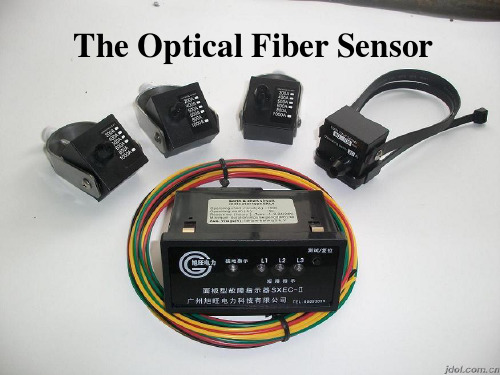
光纤传感器介绍范文光纤传感器(Optical Fiber Sensor)是一种通过利用光纤作为感应元件的传感器,能够实现对光、温度、压力、形变、流速、湿度等物理量的感测与测量。
它具有快速响应、高精度、抗电磁干扰、免维护等优点,并且在工业、农业、医疗、军事等领域有着广泛的应用。
首先,根据测量参数的不同,光纤传感器可以分为光强传感器、光频传感器和光相位传感器。
光强传感器根据光的强度变化来测量物理量,如压力传感器、形变传感器等。
光频传感器利用光的波长变化来测量物理量,如温度传感器、流速传感器等。
光相位传感器则是通过光的相位变化来测量物理量,如力传感器、应变传感器等。
其次,根据光纤结构的不同,光纤传感器可分为点式传感器和分布式传感器。
点式传感器是将传感元件集中在光纤的一段上,对目标物理量进行测量,如光纤光强传感器。
分布式传感器则是在整根光纤中布置传感元件,可以实现全面、连续的测量,如光纤拉曼温度传感器。
另外,光纤传感器还有许多特殊类型,如布拉格光纤传感器、光纤内腔传感器、光纤光栅传感器等。
布拉格光纤传感器是将布拉格光纤光栅结构应用于传感器中,通过检测光栅的特征谱线来进行测量。
光纤内腔传感器是将传感元件置于光纤内,通过控制光的温度、压力等参数的变化来检测目标物理量。
光纤光栅传感器是将光栅结构直接写入光纤中,通过测量光的衍射特性来进行测量。
光纤传感器具有许多优点,首先是灵敏度高。
光纤传感器可以实现毫微米、微米甚至纳米级的测量精度,适用于许多高精度测量应用。
其次是抗电磁干扰能力强。
光纤传感器的测量信号不受外部电磁干扰的影响,能够在电磁环境恶劣的条件下正常工作。
此外,光纤传感器还具有抗腐蚀、免维护、远程测量等优点,在工业生产、环境监测等领域有广泛的应用。
光纤传感器在许多领域都有实际应用。
在工业自动化领域,光纤传感器可用于测量温度、压力、流速、湿度等参数,实现对生产过程的监控与控制。
在农业领域,光纤传感器可以用于土壤湿度测量、植物生长监测等应用,为农业生产提供精细化管理手段。
光纤传感器的工作原理与应用研究
光纤传感器的工作原理与应用研究光纤传感器作为一种新型的传感器技术,近年来在物理、化学、生物、医学等领域得到广泛的应用。
本文将介绍光纤传感器的工作原理,并探讨其在不同领域中的应用研究。
一、光纤传感器的工作原理光纤传感器是利用光的传输特性进行测量的一种传感器。
其工作原理主要基于光的衍射、吸收、反射和散射等现象。
1. 反射型光纤传感器反射型光纤传感器是通过测量光的反射来检测被测物理量的变化。
其中,最常见的反射型光纤传感器是光纤光栅传感器。
光纤光栅传感器通过在光纤中引入周期性的折射率变化,使光在光纤中发生衍射,从而实现对物理量的测量。
2. 吸收型光纤传感器吸收型光纤传感器是通过测量光的吸收来检测被测物理量的变化。
例如,利用光纤中某些特殊材料对特定波长光的吸收特性,可以实现对气体浓度、液体浓度等物理量的测量。
3. 散射型光纤传感器散射型光纤传感器是通过测量光的散射来检测被测物理量的变化。
其中,常见的散射型光纤传感器有散射光纤传感器和拉曼光纤传感器。
散射光纤传感器通过测量光在传输过程中的散射光强度变化来实现物理量的测量,而拉曼光纤传感器则是通过测量光在传输过程中的拉曼散射来实现物理量的测量。
二、光纤传感器的应用研究光纤传感器在各个领域中都有广泛的应用研究,下面将以几个典型领域为例进行介绍。
1. 工业领域光纤传感器在工业领域中可用于温度、压力、应变、振动等物理量的测量。
例如,将光纤传感器应用于工业设备的监测与控制中,可以实时监测设备的运行状态,提前发现故障,并及时采取相应的措施。
此外,光纤传感器还可用于工业过程的在线监测,提高生产效率和产品质量。
2. 环境监测光纤传感器在环境监测中具有重要的作用。
例如,通过在地下埋设光纤传感器网络,可以实现地下水位、土壤湿度等指标的实时监测。
此外,光纤传感器还可用于大气污染物的在线监测、水质监测等环境领域的研究。
3. 医学领域光纤传感器在医学领域中的应用主要集中在生物医学成像和生物传感器方面。
光纤传感器的应用分析
光纤传感器的应用分析1光纤传感器在测量金属丝杨氏模量方面的应用金属丝的杨氏模量是衡量金属丝的性能的重要依据,因此,必须用更加准确地方法测量金属丝的杨氏模量。
而使用光纤传感器测量仪测量杨氏模量不仅操作简单,而且其结果的准确性、可靠性大大提高。
传统的测量方法是拉伸法,其基本原理是使金属丝受到砍码的作用力,这时金属丝会发生微小的形变,然后在镜尺组的光路转换中将这个微小的形变放大几倍,最后计算出杨氏模量。
而应用了光纤传感器的红外光测距仪测量的灵敏度、精确度、准确度都有很大的提高,红外线测量仪可以用来直接测量3毫米以内的微小形变,而且几乎没有误差。
另一种反射式光纤位移传感器也是用来测量杨氏模量的仪器,它采用两束多模光纤,一端合并组成光纤探头,另一端分为两束,分别是光源光纤和接受光纤。
在测量时,将传感器固定在支架上,而后通过改变杨氏模量仪上的金属丝位置,使仪表的电势差发生变化,多次测量后,通过计算得出杨氏模量。
2光纤传感器在温度测量方面的应用我们都知道光纤传感器是根据光在光导纤维中传播而传递信息进行测量的,而光在光导纤维中传播时,光的光强,波长,频率等,物理量都会受到外界温度、电磁波、电磁场的影响,会产生一定的变化,而光纤传感器在测量温度方面的应用正是利用了这一微小的变化。
利用温度引起的光纤相位变化来反映温度的变化,这种测温仪器被称为调制传感型光纤测温仪,此外,还有根据光的振幅变化、偏振态变化等原理做成的温度测量装置,而这些装置同样稍加改造,就可以用来测量其他方面的物理量。
3光纤传感器在土木工程领域的应用光纤传感器在土木工程领域也得到了广泛应用。
在土木工程领域,光纤传感器多用来测量大型的结构、桥梁的安全性能、混凝土结构变形及内部的应力等等,最重要的是光纤传感器作为一种新型的应变传感器而发挥出巨大的作用。
光纤传感器与普通传感器相比一般来说更加小巧,因此可以深入混凝土的损伤裂缝中进行测量,以确定混凝土内部损伤的形式及扩展方式;光纤传感器质量比较轻,能够倒置粘贴在天花板,或野外的树枝及山洞壁上,可以从各种不同的角度进行测量;土木工程领域一般所需要的数据都比较精确,光纤传感器恰好满足这一条件,据调查,使用光纤传感器所测出的数据更加符合标准,能为土木工程的施工建设提供详细准确的数据参考。
光纤传感器的研究及应用研究

光纤传感器的研究及应用研究
光纤传感器是应用光学原理实现测量、监测和控制的一种高精度、高灵敏度的传感器。
其基本原理是利用光纤将被测物理量转换
成光学信号,通过光学元件实现测量。
近年来,随着材料科学、信
息技术和光学技术的发展,光纤传感器在工业、军事、医疗、环境
监测等领域得到了广泛的应用。
光纤传感器的研究主要是从理论计算、光学元件、光纤材料、
信号处理技术和应用开发等方面进行的。
其中,光学元件是构成光
纤传感器的重要组成部分,主要有光纤光栅、薄膜、镜片等。
光纤
光栅是一种新型的光学元件,具有高灵敏度、高解析度、结构简单、易于集成等优点,可应用于压力、温度、应力等复杂环境的测量。
在光纤传感器的应用中,信号处理技术也是关键的研究方向,主要
有数字信号处理、模拟信号处理和单片机控制等技术。
目前,光纤传感器具有广泛的应用,主要包括温度、压力、应变、振动、化学物质、流量等领域。
例如,在工业领域,光纤传感
器可以应用于自动化生产线、机械设备、石油化工等领域的测量和
监测;在医疗领域,光纤传感器可以应用于体内医疗设备、医学诊
断等领域;在环境监测领域,光纤传感器可以应用于大气污染、水
资源管理等方面的监测和调控。
光纤传感器是一种具有广泛应用前景的高新技术,其研究和应
用对提高生产效率、改善环境质量、保障人类健康等方面具有重要
意义和作用。
1。
- 1、下载文档前请自行甄别文档内容的完整性,平台不提供额外的编辑、内容补充、找答案等附加服务。
- 2、"仅部分预览"的文档,不可在线预览部分如存在完整性等问题,可反馈申请退款(可完整预览的文档不适用该条件!)。
- 3、如文档侵犯您的权益,请联系客服反馈,我们会尽快为您处理(人工客服工作时间:9:00-18:30)。
光纤传感器的应用研究摘要本文介绍了光纤传感器研究的目的、意义及其发展趋势,通过分析研究各类光纤传感器的基本原理,设计出了几种功能较完善的光纤传感器。
首先从研究光纤传感器的工作原理出发,分析各种光纤传感器的结构和原理,通过对原有光纤传感器的结构和控制机理的分析,结合学过的电子知识,设计光纤传感温度计、光纤传感压强计等。
在整个研究过程中采取实验和理论相结合的方式。
1绪论光纤传感器是70年代末发展起来的一种新型传感器,它具有不受电磁场影响,本质上安全防爆,体积小,耐腐蚀,灵敏度高等优点。
可用在传统传感器难以涉足的极端恶劣环境,所以在军事、航空航天、生物医学、建筑施工等领域被受青睐。
因此对光纤传感器的研究具有很重要的现实意义。
传感技术是近几年热门的应用技术,传感器在朝着灵敏、精确、适应性强、小巧和智慧化的方向发展。
在这一过程中,光纤传感器这个传感器家族的新成员倍受青睐。
光纤具有很多优异的性能,例如:抗电磁干扰和原子辐射的性能,径细、质软、重量轻的机械性能,绝缘、无感应的电气性能,耐水、耐高温、耐腐蚀的化学性能等,它能够在人达不到的地方(如高温区),或者对人有害的地区(如核辐射区),起到人的耳目的作用,而且还能超越人的生理界限,接收人的感官所感受不到的外界信息。
光纤传感器是最近几年出现的新技术,可以用来测量多种物理量,比如声场、电场、压力、温度、角速度、加速度等,还可以完成现有测量技术难以完成的测量任务。
在狭小的空间里,在强电磁干扰和高电压的环境里,光纤传感器都显示出了独特的魅力。
因此,光纤传感技术应用的研究具有很好的前景。
光纤传感优点:灵敏度较高;几何形状具有多方面的适应性,可以制成任意形状的光纤传感器;可以制造传感各种不同物理信息(声、磁、温度、旋转等)的器件;可以用于高压、电气噪声、高温、腐蚀、或其它的恶劣环境;而且具有与光纤遥测技术的内在相容性。
光纤传感器用光作为敏感信息的载体,用光纤作为传递敏感信息的媒质。
因此,它同时具有光纤及光学测量的特点。
①电绝缘性能好。
②抗电磁干扰能力强。
③非侵入性。
④高灵敏度。
⑤容易实现对被测信号的远距离监控2光通信简介2.1有线光通信有线光通信的传输媒介为光纤。
光纤是光导纤维的简称,是用光透射率高的电介质构成的光通路。
它是一种介质圆柱光波导。
所谓“光波导”是指将以光的形式出现的电磁波能量利用全反射的原理约束并引导光波在光纤内部或表面附近沿轴线方向传播。
2.2 无线光通信无线光通信系统(FSO)以大气作为传输媒质来进行光信号的传送。
只要在适当距离的收发两个端机之间存在无遮挡的视距路径和足够的光发射功率,即可实现无线光通信。
3光纤传感器简介3.1光纤传感器的结构原理以电为基础的传统传感器是一种把测量的状态转变为可测的电信号的装置。
它的电源、敏感元件、信号接收和处理系统以及信息传输均用金属导线连接,见图(a)。
光纤传感器则是一种把被测量的状态转变为可测的光信号的装置。
由光发送器、敏感元件(光纤或非光纤的)、光接收器、信号处理系统以及光纤构成由光发送器发出的光经源光纤引导至敏感元件。
这时,光的某一性质受到被测量的调制,已调光经接收光纤耦合到光接收器,使光信号变为电信号,最后经信号处理得到所期待的被测量。
可见,光纤传感器与以电为基础的传统传感器相比较,在测量原理上有本质的差别。
传统传感器是以机—电测量为基础,而光纤传感器则以光学测量为基础。
光是一种电磁波,其波长从极远红外的lmm到极远紫外线的10nm。
它的物理作用和生物化学作用主要因其中的电场而引起。
因此,讨论光的敏感测量必须考虑光的电矢量E的振动,即A——电场E的振幅矢量;ω——光波的振动频率;φ——光相位;t——光的传播时间。
可见,只要使光的强度、偏振态(矢量A的方向)、频率和相位等参量之一随被测量状态的变化而变化,或受被测量调制,那么,通过对光的强度调制、偏振调制、频率调制或相位调制等进行解调,获得所需要的被测量的信息。
3.2光纤传感器的分类光纤传感器的分类有多种形式,可以根据光纤在传感器中的作用进行分类,也可以根据光受被测对象的调制形式进行分类3.2.1根据光纤在传感器中的作用分类光纤传感器分为功能型、非功能型和拾光型三大类。
1)功能型(全光纤型)光纤传感器利用对外界信息具有敏感能力和检测能力的光纤(或特殊光纤)作传感元件,将“传”和“感”合为一体的传感器。
光纤不仅起传光作用,而且还利用光纤在外界因素(弯曲、相变)的作用下,其光学特性(光强、相位、偏振态等)的变化来实现“传”和“感”的功能。
因此,传感器中光纤是连续的。
由于光纤连续,增加其长度,可提高灵敏度。
2)非功能型(或称传光型)光纤传感器光纤仅起导光作用,只“传”不“感”,对外界信息的“感觉”功能依靠其他物理性质的功能元件完成。
光纤不连续。
此类光纤传感器无需特殊光纤及其他特殊技术,比较容易实现,成本低。
但灵敏度也较低,用于对灵敏度要求不太高的场合。
3)拾光型光纤传感器用光纤作为探头,接收由被测对象辐射的光或被其反射、散射的光。
其典型例子如光纤激光多普勒速度计、辐射式光纤温度传感器等。
3.2.2根据光受被测对象的调制形式分类(1)强度调制型光纤传感器是一种利用被测对象的变化引起敏感元件的折射率、吸收或反射等参数的变化,而导致光强度变化来实现敏感测量的传感器。
有利用光纤的微弯损耗;各物质的吸收特性;振动膜或液晶的反射光强度的变化;物质因各种粒子射线或化学、机械的激励而发光的现象;以及物质的荧光辐射或光路的遮断等来构成压力、振动、温度、位移、气体等各种强度调制型光纤传感器。
优点:结构简单、容易实现,成本低。
缺点:受光源强度波动和连接器损耗变化等影响较大。
(2)偏振调制光纤传感器是一种利用光偏振态变化来传递被测对象信息的传感器。
有利用光在磁场中媒质内传播的法拉第效应做成的电流、磁场传感器;利用光在电场中的压电晶体内传播的泡尔效应做成的电场、电压传感器;利用物质的光弹效应构成的压力、振动或声传感器;以及利用光纤的双折射性构成温度、压力、振动等传感器。
这类传感器可以避免光源强度变化的影啊,因此灵敏度高。
(3)频率调制光纤传感器是一种利用单色光射到被测物体上反射回来的光的频率发生变化来进行监测的传感器。
有利用运动物体反射光和散射光的多普勒效应的光纤速度、流速、振动、压力、加速度传感器;利用物质受强光照射时的喇曼散射构成的测量气体浓度或监测大气污染的气体传感器;以及利用光致发光的温度传感器等。
(4)相位调制传感器g E h ≥υg E h ≥υ其基本原理是利用被测对象对敏感元件的作用,使敏感元件的折射率或传播常数发生变化,而导致光的相位变化,使两束单色光所产生的干涉条纹发生变化,通过检测干涉条纹的变化量来确定光的相位变化量,从而得到被测对象的信息。
通常有利用光弹效应的声、压力或振动传感器;利用磁致伸缩效应的电流、磁场传感器;利用电致伸缩的电场、电压传感器以及利用光纤赛格纳克(Sagnac )效应的旋转角速度传感器(光纤陀螺)等。
这类传感器的灵敏度很高。
但由于须用特殊光纤及高精度检测系统,因此成本高。
4光纤传感温度计的设计这里我们设计的是透射型半导体光纤温度传感器。
当一束白光经过半导体晶体片时,低于某个特定波长λg 的光将被半导体吸收,而高于该波长的光将透过半导体。
这是由于半导体的本征吸收引起的,λg 称为半导体的本征吸收波长。
电子从价带激发到导带引起的吸收称为本征吸收。
当一定波长的光照射到半导体上时,电子吸收光能从价带跃迁入导带,显然,要发生本征吸收,光子能量必须大于半导体的禁带宽度E g ,即h —普朗克常数;v —光频率因λ=c /v ,则产生本征吸收条件:,即h —普朗克常数;v —光频率因λ=c /v ,则产生本征吸收条件:g 的光,因此,对于波长大于λg 的光,能透过半导体,而波长小于λg 的光将被半导体吸收。
不同种类的半导体材料具有不同的本征吸收波长,图为在室温(20℃)时,120μm 厚的GaAs 材料的透射率曲线。
GaAs 在室温时的本征吸收波长约为880nm 左右,半导体的吸收光谱与E g 有关,而半导体材料的E g 随温度的不同而不同,E g 与温度t 的关系可表示为:式中:E g (0)——绝对零度时半导体的禁带宽度;α——经验常数(eV /K);β——经验常数(K)。
对于GaAs 材料,由实验得到 α =5.8×10⁻⁴eV/K β=300K由此可见,半导体材料的E g 随温度上升而减小,亦即其本征吸收波长λg 随温度上升而增大。
反映在半导体的透光特性上,即当温度升高时,其透射率曲线将向长波方向移动。
若采用发射光谱与半导体的λg(t )相匹配的发光二极管作为光源,则透射光强度将随着温度的升高而减小。
即通过检测透射光的强度或透射率,即可检测温度变化。
()eVE g 522.10=The application of optical fiber sensorAbstract: This paper describes the purpose of researching on FOS and its development. Based on the principle of all kinds of FOS,finishing some good function FOS.Firstly,we study the principle of FOS which helps me know the structure and theory.Secondly,because of the anlysis of the old FOS’framework,we combine some electric knowledge to design a fiber pressure sensor and a fiber temperature pressure.Between the whole course of the research,we take the measure of experimentation and theory studying.1. IntroductionOptical fiber sensor is developed at the end of 70 s as a new type of sensor, it has not affected by electromagnetic field effect, in essence safety explosion-proof, small size, corrosion resistance, the advantages of high sensitivity. Used in traditional sensor is difficult to set foot in the extreme environment, so in the military, aviation, biological medicine, building construction field is popular. So to optical fiber sensor research has very important practical significance. Sensing technology is popular in recent years, the application of the technology in the sensitive, accurate sensor, strong adaptability, cabinet and wisdom of the direction of development. In this process, optical fiber sensors the sensor to the new members of the family is extremely popular. Optical fiber has many excellent properties, such as: the electromagnetic interference and atomic radiation performance, diameter is fine, soft and light weight of mechanical properties, insulation, without induction electrical properties, water resistant, high temperature resistant and corrosion resistance of the chemical properties, it can not reach people places (such as high), or harmful to the person of the area (such as nuclear area), plays the role of the refreshing, and still can transcend boundaries, receiving of physiological the senses of not feeling outside information. Optical fiber sensor is a new technology in recent years, can be used to measure DuoZhong physical quantities, such as sound field, electric field, pressure, temperature, angular velocity, acceleration, etc, but also can complete the existing measuring technology difficult to complete measuring task. In the narrow space, in strong electromagnetic interference and high voltage environment, optical fiber sensors shows the unique charm. Therefore, the optical fiber sensing technology application research has the very good prospects. The optical fiber sensing advantage: high sensitivity; Geometric shape has many aspects of adaptability, can be made into any shape of the optical fiber sensor; Can manufacture various physical sensor information (sound, magnetic, temperature, rotation, etc.) of the device; Can be used for high pressure, electrical noise, high temperature, corrosion, or other harsh environment; But has the optical fiber sensing and the internal compatibility. Optical fiber sensor light sensitive information carrier, as the optical fibre as sensitive information transmission medium. Therefore, it also has the characteristics of optical fiber and optical measurement.(1) the electric insulation performance is good.(2) anti-electromagnetism interference ability.(3) the non-invasive.(4) the high sensitivity.(5) to be easy to implement the measured signal remote monitoring2. Optical communication introduction2.1 Optical cableCable of the transmission medium for optical fiber optical communication. Optical fiber is the abbreviation of optical fiber transmission rate is light, high dielectric consists of the light path. It is a kind of dielectric column optical waveguide. The so-called "optical waveguide" means in the form of light will be of electromagnetic energy use the principle of total reflection constraint and the waves in optical fiber guide inside or near the surface along the axis direction spread2.2 Wireless Optical CommunicationFSO system (FSO) to the atmosphere as a transmission medium to light signals transmitted. As long as the proper distance in the sending and receiving two end between machine without sunscreen, beyond the path and enough light transmission power, can realize the wireless optical communication3. Optical fiber sensor profile3.1 Optical fiber sensor structure principleBased on the traditional sensor is a measurement of the state transition for measurable signals of the device. Its power supply, sensitive components, receiving signal and processing system and information transmission all use metal wire connection, see chart (a). Optical fiber sensor is a kind of the measurement of the state transition for the light signal can be measured by the device. The transmitter, light sensitive components (optical fiber or the optical fiber), light receptors, signal processing system and the optical fiber by light a transmitter the light source of the optical fiber guide to sensitive components. At this time, the light of a certain property is measured by the regulation, already light receiving the coupling to light receptors, make the light signal into electrical signals, and finally get the signal processing to be measured. Visible, optical fiber sensor and to call for the traditional sensor based compared in measuring principle, have fundamentally different. Traditional sensor in machine, electricity measurement for the foundation, and the optical fiber sensor is based on optical measurement.Light is an electromagnetic wave, the far infrared wavelengths from extremely the LMM to a far ultraviolet 10 nm. Its physical function and biological chemistry because one of the main electric field and cause. Therefore, to discuss the light sensitive measurement must be consider light of electricity vector of the vibration of the E, namelyA-the amplitude of the vector field E; Omega of the waves of light-the vibration frequency;Phi-light phase; T-light transmission time.Visible, if make light intensity, polarization direction of A (vector), frequency and phase one of the parameters such as with the change of state is measured and change, or is measured by A, then, through the light intensity modulation, polarization modulation frequency modulation, or phase modulation of demodulation, gain needed be measured information.3.2 The classification of the optical fiber sensorThe classification of fiber optic sensor has DuoZhong form, can according to optical fiber sensorin the role of classification, can also according to light modulation of the tested object by the formof classification3.2.1According to the function of optical fiber sensor in classificationOptical fiber sensor into functional, the functional and picked up three types of light type1).Functional (all fiber type) optical fiber sensorUse has sensitive to outside information ability and the ability of testing (or special optical fiber optical fiber sensor), will "pass" and "feeling" integrated sensor. Not only the light on optical fiber effect, and still use of optical fiber in the external factors (bending, phase transformation) function, its optical properties (light intensity, phase, the change of polarization, etc.) to realize "pass" and "sense" function. Therefore, the optical fiber sensor is continuous. Due to the continuous fiber, increase its length, can improve the sensitivity2).The functional (or says light-transmission type) optical fiber sensorThe only light guide fiber role, "the" not only "sense" to outside information, "feel" function depend on other physical properties of functional component finish. Optical fiber discontinuous. This kind of optical fiber sensor to need not special optical fiber and other special technology, much easier to achieve, and the cost is low. But sensitivity is low, the sensitivity requirement is not too high for the occasion.3).Pick up the light fiber-optic sensorWith optical fiber probe, as received from tested object radiation light or be its reflection, scattering of light. Its typical examples such as optical fiber laser doppler velocity gauge, FuSheShi optical fiber temperature sensors, etc.3.2.2 Intensity modulation fiber-optic sensorsIt is a use of tested object of the change sensitive components the refractive index, absorb or reflection of the parameters such as changes, and lead to the light intensity changes to achieve sensitive sensors measuring. Use of optical fiber bending loss of micro; The material of the absorption characteristics; Vibration film or LCD reflected light intensity change; Materialbecause of all sorts of particle rays or chemical, mechanical incentive and shine phenomenon; And the material of the fluorescent light radiation or the road block to form such as pressure, vibration, temperature, displacement, gas, etc. Various kinds of intensity modulation fiber-optic sensors.Advantages: simple structure and easy to implement, and the cost is low.Faults: light intensity by fluctuations and connectors loss of changes greatly.(2).Polarization modulation fiber-optic sensorsIt is a kind of polarization of light changes to deliver the tested object information of the sensor. Favorable light in magnetic field in the medium of the spread of Faraday effect of current, magnetic field sensors made; Use light in the electric field spread a piezoelectric crystal of the bubble's effect of the electric field, make voltage sensor; The light of the use of matter the effect of pressure, vibration or a sound sensors; And the use of optical fiber birefringence sex constitute the temperature, pressure, vibration for the sensor. This kind of sensor can avoid light source of strength changes of ah, so high sensitivity.(3).Frequency modulation fiber-optic sensorsIt is a use of monochromatic shot to the object to be tested the reflected light changes the frequency of the monitor to the sensor. Use of sports objects reflect light and scattering light doppler effect of the optical fiber speed, vibration, pressure, flow velocity and acceleration sensors; By using material glare of the Raman scattering when a measuring gas concentration or monitoring air pollution gas sensors; And the use of organic light of the temperature sensor, etc.Phase modulation sensor(4).he basic principle is to use tested object to sensitive components in the role of the sensitive components of the refractive index or the transmission constant change, and lead to the phase of the light change, make the two beams of the interference fringes monochromatic produces change, through the test of the interference streak to determine the amount of variation of the light of phase change, and get tested object of information. Usually run out of the favorable effect sound, pressure or vibration sensor; Use magnetostrictive effect of the current, magnetic field sensors; Use electricity to the electric field, adjustable voltage sensor and the use of optical fiber, g (Sagnac stablished) effect of angular velocity sensor (optical fiber gyro), etc. This kind of sensor sensitivity high. But because must use special optical fiber and high precision testing system, so the cost is high.4.The design of optical fiber sensing a thermometerof light This is because the semiconductor the eigenvalue of the absorption of the cause, lambda g called semiconductor the eigenvalue of the absorption wavelength. Electronic valence band inspired to guide from with the absorption of the eigenvalue called cause absorption. When certain wavelengths of light to illuminate the semiconductor, electronic absorb the light from the price jump with having the conduction band, obviously, to happen on the absorption, photon energy must be greater than the width of the semiconductor with Eg, namelyg E h ≥υg E h ≥υProduce the kind of absorption conditions :H-Planck's constant; V-light frequenciesFor lambda = c/v, it producesSo, for the wavelength of the light, greater than the lambda gSo, for the wavelength of the light, greater than the lambda g can pass through, and less than the wavelength semiconductor light will be lambda g semiconductor absorption. Different kinds of semiconductor materials have different the eigenvalue of the absorption wavelength, the graph is in room temperature (20 ℃), 120 mu m thick GaAs transmission rate curve of the material. GaAs at room temperature absorbed the eigenvalue of the wavelengths of about 880 nm or so, the absorption spectra of the semiconductor and Eg, semiconductor materials about the Eg with temperature different and different, Eg and the relationship between temperature t can be expressed as:This shows, Eg of semiconductor materials with temperature increasing and decreases, and that is the kind of the absorption wave lambda g increases with temperature increasing. Reflected in the semiconductor in characteristics, and that is when the pervious to light the temperature rises, the transmission rate curve will long to direction. If you use the emission spectrum andsemiconductor lambda g (t) matching leds as the light source, the transmission light intensity will decrease with the rise of temperature. That is, through the test of strength or transmitted light transmission rate, can testing temperature changes.。