EOLO MINI 说明书
MiniF28027用户手册
MiniF28027 Piccolo开发套件用户手册第一章 MiniF28027功能简介 (2)1.1 MiniF28027简介 (2)1.2 MiniF28027硬件接口 (2)1.3 MiniF28027的使用 (4)1.4 CCS简介 (5)第二章软件安装和仿真器驱动 (5)2.1 CCS安装 (5)2.2 加载仿真器驱动 (5)第三章 MiniF28027开发板实验 (6)3.0 实验前的准备 (6)3.1实验1 LED闪烁实验 (7)3.2实验2 定时器控制LED变频率闪烁实验 (7)3.3实验3 EPWM波形实验 (8)3.4实验4 ADC实验 (8)第四章:用户程序固化和加密 (8)4.1烧写FLASH (8)4.2 加密 (8)4.3 解密 (10)5 注意事项 (10)6 免责声明 (11)第一章 MiniF28027功能简介1.1 MiniF28027简介MiniF28027是科州电子在2010年推出的Piccolo系列迷你开发套件。
它包含两个部分:XDS100v1仿真器,和MiniF28027开发板,体积如半张名片,小巧玲珑。
它的出现为开发Piccolo系列微处理器提供了极大的方便。
用户可以以极高的性价比在其基础上进行二次开发,学习,或者用以做为演示并销售Piccolo系列芯片的载体。
该系统的XDS100v1仿真器提供了14针标准JTAG仿真接口,具有极好的通用性和兼容性。
XDS100v1仿真器可以调试的芯片有: TMS320C28x, TMS320C54x,TMS320C55x, TMS320C64x+, and TMS320C674x 。
科州电子的XDS100v1仿真器采取TI原厂配置,兼容CCS3.3和CCS4。
F28027目标板上集成了一个LED,由GPIO34驱动。
其他资源全部引出,方便用户做二次开发。
开发套件清单:◆XDS100v1 仿真器(支持CCS3.3和CCS4)◆TMS320F28027PTS迷你系统板一块◆光盘资料一张:含原理图,实验代码,视频教程,软件开发工具,芯片资料,赠送电子书礼包。
velocap tbox mini说明书
velocap tbox mini说明书产品产品名称车连易互联盒所属品牌CarlinKit 车连易产品型号CPC200-Tbox Mini产品认证SRRC 无线电发射设备型号核准证硬件系统Android 11.0处理器QCM2290,四核64位ARM Cortex™-A53 处理器 @ 2.0 GHz 11nm工艺GPUAdreno™ 702内存3GB运行内存 + 32GB机身内存版本欧亚EAU版本(亚洲、欧洲国家)、北美NA版本(北美、加拿大)WiFi频率02.11 a/b/g/n/ac, 2.4G+5G蓝牙版本4.2 E+5.0 E电源输入5V±0.2V 1.0A产品功耗5W产品材质ABS+PC分辨率自适应(保持原有协议分辨率)适配手机无线CarPlay:iPhone 6 及以上手机 / iOS 10.0 及以上系统;无线Android Auto:Android 10.0 及以上系统的安卓手机,部分要求Android 11.0 及以上系统适配车机支持原车自带有线CarPlay功能的汽车主机语言全球多种语言,例:阿拉伯文、中文、英文、法文端口LED指示灯、Type-C母口、TF卡座、SIM卡座线材USB-A to USB-C*1 USB-C to USB-C*1 L=300mm 蜂窝网络制式其它产品尺寸79.×79.×14.7mm包装尺寸100×100×40mm产品净重0.064kg包装毛重0.165kg产地中国大陆。
koopor mini 说明书
连续三下点火按键,进入我们的图表菜单模式,这种菜单来说还是比英文好,我英文是卫生女老师教的,所以啥也没记住。
我们的图表是顺序是:
1、温控,功率功能切换,显示w开头的是功率模式,而他temp mode是温控模式。
2、这个图表显示温控发热丝的选择, coil nicke《镍丝》l ,coil titanium 《钛丝》。
3、tc图表显示的是口感模式,就是上面提到的模式。
柔和,标准,暴力,这是八戒自己的叫法,不知道官方的意思到底是什么。
4、熄灭时间,也就是我们显示在多久之后熄灭,这个熄灭在开启,第一下是有延迟的。
需要先按一下在按使用。
5、是个英文的pi,里面的意思是几口几秒复位的意思。
也就是重置。
6、旋转屏幕,也就是一个长方块左右都友旋转的箭头的标志,就是旋转屏幕,左右手的意思。
7、tcr值,这个是我没有想到的,现在很多厂家都在研究tcr值的问题。
tcr值也就是金属含量的的数值,在百度上是可以查到的,这样也就可以设置tcr 来修改发热丝出厂厂家的不同经进行一个修改。
8、是aio的英文字母,应该是考虑到盒子有一定的内阻,才这样设计的,有一些小玩家会纠结电阻的问题,那么这个功能就有用了,因为你可以自己修改阻值。
9、这个就不用说了,因为就是关机的意思,很多电子设备都是用的这种这种图表的代表关机。
意大利依玛Mini Eolo 24-28-3e说明书

指示及说明手册壁挂式家用燃气锅炉锅炉制造及检验标准: CE EN483国标国标GB6932-2001MINI Eolo 24/28 3C/ECT/T 228-2006尊敬的用户感谢您选择Immergas 公司产品,我们的产品质量卓越,能让您长期享有健康和安全。
作为Immergas 公司的用户,您可放心使用我们提供的专业优质的特许售后服务,我们的服务管理到位、更新及时,能够为您的锅炉持续高效运转提供有力保障。
请仔细阅读本手册中的内容:我们将就如何正确使用该设备向您提供有用的建议,按照这些建议操作,您才能从Immergas 产品中获得最大享受。
请尽快与您所在区域的特许售后服务中心取得联系,要求他们进行运转情况初始检查。
我们的技术人员将会检查该设备是否能够正常工作,并对其进行必要的校调,同时还会告诉您正确使用锅炉的方法。
您也可以向Immergas 特许售后服务中心提出要求,派人进行故障检查及日常维护工作:特许售后服务中心可以向您提供原装配件,且中心所提供的各项服务均是在制造商的专门指导下进行的。
注意事项使用说明是产品不可分割的重要组成部分,在进行设备转让时应当将设备连同本手册一并交与设备受让人或承租人。
用户应妥善保管并仔细阅读本手册,因为其中涉及到安装、使用和维护过程中的重要安全事项。
根据现行法律的规定,必须由专业人士依据法律规定完成供暖设备设计。
在安装和维护过程中必须遵守现行法律法规的要求及制造商的指示,同时安装和维护过程应当由专业技术人员来实施,即那些具有该设备相应领域专业技能的人员。
安装错误可能对人员、动物或物品造成重大损失,在这种情况下制造商将不承担任何责任。
设备维护必须由专业技术人员进行,在这方面,Immergas 特许售后服务中心能为您提供合格专业的服务。
请勿在本设备明确规定的适用范围之外使用本设备。
任何其他用途都将被视为违规事项并可能导致危险发生。
由于不遵守当前技术法规、法律法规或本手册(或其他制造商提供的文件资料)说明而导致的任何安装、使用、维护故障,其可能造成的任何危害均不可被认定为制造商在合同内及合同外的赔偿责任,同时,当出现上述问题时,保修服务随之中止。
太尔时代MINI说明书

目录
1.简介.............................................................. 1 1.1 手册使用须知..................................................1 1.2 注意事项 ...................................................... 1 1.2.1 安全....................................................... 1 1.2.2 保护措施................................................... 2
50%之间,如超过此范围,可能会影响成型质量。
2
2.概述
UP!三维打印机的设计理念是简易、便携。只需要几个按键,即使您从来没 有使用过3D打印机,也可以很容易地制造出自己喜欢的模型。该打印机的原理 是首先将ABS材料高温熔化挤出,并在成型后迅速凝固,因而打印出的模型结实 耐用。 2.1 外观
1、打印机前视图
法律声明
我们有权在未通知的情况下对本手册的相关内容进行修改。
我们对于因参照本手册而造成的任何损失(包括后续损失)均不承担责任, 其中包括因印刷错误和其他出版错误造成的损失。在未得到事先书面同意的情况 下,任何人不得对此说明书进行修改、复印或翻译。本手册受版权保护,且本公 司保留对本手册的最终解释权。
12
3.2 使用基本功能 3.2.1 启动程序
点击桌面上的图标
,程序就会按照如下图示打开:
(主操作界面)
3.2.2 载入一个 3D 模型
mini-pro 用户手册说明书
用户手册文件编号:RGB-RD-UM-mini-pro C000版本:V1.0目录声明 (4)第一章产品简介 (6)1.1随附配件 (6)1.2产品概述 (7)1.2.1主要特点 (7)1.2.2前面板图示 (8)1.2.3接口面板图示 (9)1.2.4外形尺寸图 (10)第二章产品安装 (11)2.1连接电源 (11)2.2连接信号源 (11)2.3连接监看设备 (12)2.4连接麦克风和外接监听设备 (12)2.5连接USB作为网络信号源 (13)2.6连接计算机 (13)2.7打开mini-pro (14)第三章产品使用 (15)3.1触摸屏操作 (15)触摸屏简介 (15)划屏功能 (15)预设调用菜单 (16)3.2信号直切 (16)设置切换特效 (16)设置切换时长 (17)3.3信号预监切换与多画面分割监看 (17)3.4画中画设置 (17)设置画中画布局 (18)设置图层大小 (18)3.4预设场景的保存和快捷调用 (18)3.5视频输出设置 (19)HDMI输出 (19)USB输出 (20)3.6音频设置 (21)3.7抠图设置 (22)3.8PTZ控制与预设位置保存 (23)3.9连接USB进行硬盘录制 (24)第四章网络推流 (26)4.1OBS推流 (26)4.2VMix推流 (30)4.3钉钉直播 (31)4.4腾讯会议直播 (32)4.5飞书会议直播 (33)第5章XPOSE mini软件操作 (35)5.1.连接mini与电脑 (35)使用网线直接连接 (35)使用静态直连 (36)使用路由器无线连接 (37)5.2使用XPOSE mini (38)搜索设备 (38)PTZ摄像头设置 (39)色度抠图 (40)测试模式 (40)密码保护 (41)T-Bar校正 (41)流媒体 (42)5.3升级指导 (43)第六章订购编码 (45)6.1产品编码 (45)第七章附录 (46)7.1规格 (46)7.2FAQ (47)7.3术语和定义 (48)7.4修订记录 (54)第八章技术支持 (55)首先感谢您选购我们的产品!为了让您迅速掌握如何使用这款创意拼接器,我们为您送上了详细的产品使用手册。
MAGICO Mini 用户手册说明书
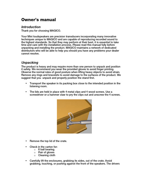
Owner’s manualIntroductionThank you for choosing MAGICO.Your Mini loudspeakers are precision transducers incorporating many innovative techniques unique to MAGICO and are capable of reproducing recorded sound to the highest standards. So that they may perform at their best, it is essential to take time and care with the installation process. Please read this manual fully before unpacking and installing the product. MAGICO maintains a network of dedicated distributors who will be able to help you should you have any problems your dealer cannot resolve.UnpackingThe product is heavy and may require more than one person to unpack and position it safely. We recommend you wear the provided gloves to avoid finger printing. Observe the normal rules of good posture when lifting heavy objects to avoid strain. Remove any rings and bracelets to avoid damage to the surfaces of the product. We suggest that you unpack and properly position the stand first.•Transport the speaker in its packing box close to the intended position in the listening room.•The lids are held in place with 4 metal clips and 4 wood screws. Use a screwdriver or a hammer claw to pry the clips out and unscrew the 4 screws.•Remove the top lid of the crate.•Check in the carton for:o 6 ball bearing.o Pair of gloveso Cleaning cloth•Carefully lift the enclosures, grabbing its sides, out of the crate. Avoid grabbing, touching, or pushing against the front of the speakers. The driversare exposed and could sustain damage if directly touched or handled. Wesuggest you retain the packing for future use.MAGICO has provided coupling solution for both hard and soft floors. You can also experiment using no feet at all. Please choose the appropriate coupler and make sure the stands are secure in their place before mounting the speakers on them.Speaker and stand interfacePlace the 3 ball bearings in the concave circular recesses on the top of the stand. Position the speaker’s bottom recesses directly on to the ball bearings.Mini handlingPlease avoid pushing or pulling on the Mini top. Always slide or lift the stand if needed.PositioningFinding the optimum position in the room may involve a certain amount of experimentation, but as an initial guide:•Position the speakers and the centre of the listening area approximately at the corners of an equilateral triangle.•Keep the speakers at least 2-3m apart to maintain left-right separation.ConnectionsAll connections should be made with all electronic equipment (amplifiers, preamplifiers) turned off.There is one pair of terminals at the back of the speaker. The terminals are insulated to prevent any likelihood of electrical shock, even when the speakers are used with the highest powered amplifiers, and accept a variety of cable termination to suit most applications. DO NOT use tools to tighten the binding posts.Break-inA loudspeaker is a mechanical device and as such requires an extended initial period of normal use during which a noticeable improvement in sound quality will occur.Do not attempt to accelerate the break-in process by playing sine waves, tone sweeps or other generated signals.CareFor wood enclosures, occasionally use a soft dry cloth, to wipe off dust.For aluminum panels, use lint free soft cloth (provided), dampened with warm slightly soapy, water only (a small drop of dishes soap will do).DO NOT use cleaners that contain ammonia, strong solvents, or abrasive materials. Use of these materials can degrade, scratch, or DESTROY the finish.Specifications:Description2-way sealed enclosure with matching stand monitor Frequency response (-/+ 2db) 40Hz – 40KHz (in room)Efficiency (2.8V/1m)87dbNominal impedance 4Crossover frequency2KHzPower handling<250WDimensions (HxWxD)Mini 16”x 12” x 17” / Stand 28” 15” 19”Weight Mini 70lbs / stand 110lbsLimited WarrantyDear MAGICO Purchaser,This product has been designed and manufactured to the highest quality standards. However, if something does go wrong with this product, MAGICO and its national distributors warrant the replacement of defective parts including labor (exclusions may apply) in any country served by an official MAGICO distributor. This limited warranty is valid for a period of 3 years from the date of purchase or two years for electronics including amplified loudspeakers.Terms and Conditions1.The warranty is limited to the repair of the equipment. Neither transportation,shipping, nor any other costs, nor any risk for removal, transportation andinstallation of products is covered by this warranty.2.This warranty is only valid for the original owner. It is not transferable.3.This warranty will not be applicable in cases other than defects in materialsand/or workmanship at the time of purchase and will not be applicable:•For damages caused by incorrect installation, connection or packing,•For damages caused by any use other than correct use described in the user manual, negligence, modifications, or use of parts that are not madeor authorized by MAGICO,•For damages caused by faulty or unsuitable ancillary equipment,•For damages caused by accidents, lightning, water, fire heat, extreme weather condition, war, public disturbances or any other cause beyondthe reasonable control of MAGICO and its appointed distributors,•For products whose serial number has been altered, deleted, removed or made illegible,•If repairs or modifications have been executed by an unauthorized person.4.This guarantee complements any national/regional law obligations of dealersor national distributors and does not affect your statutory rights as acustomer.5.Unauthorized dismantling of this product will render this warranty void.6.MAGICO strives to manufacture the very finest possible equipment, andtherefore reserves the right to make changes in design and improvementsupon its products, without necessarily assuming an obligation to retrofit such changes to it’s previously manufactured models.。
MINI ONE 中文说明书

3
2、GYDIRECT-----修正方向選擇 注意:先確定舵桿打右時,尾旋翼的方向是正確的右舵。若相反,請由遙控器內部的 Servo Reverse 功能中的 Rudder 項目逆轉,直 到尾舵方向正確為止。
摇头方向
摇头方向
尾翼推进
尾翼推进
選擇項目
內容
NORM
MINI ONE 置于锁尾模式(AVCS,LED 常亮),將直昇機抬起,將機頭向左移動,尾舵應該向右修正,若尾舵向左修
● 把 MINI ONE 连接到接收器上,此时不要把舵机连接到 MINI ONE 上。
is ● 将感度通道分配到发射机上一个两点开关,便于正常模式(Normal)和锁尾(角度向量控制系统 ACVS)模式的切换。
● 确保发射机微调和辅助微调都置零,禁止主翼螺距和尾翼螺距混控。给 MINI ONE 接通电源,打开感度开关,检查发光二级管(LED)
MINI ONE
MEMS AVCS GYRO
istered 前言 MINI ONE 是一款高精度的模型直升飞机陀螺仪,它能带给你最高标准的操作性能。高质量、高性能传感器和控制器,使得 MINI ONE 具备了非常稳定的偏航率而不受外界变量的影响,例如直升机的旋翼旋转速度、十字盘载荷、飞行速度以及风等。这种特点是其作复杂的 g 皮鲁埃特旋转 3 维机动的必备条件。该陀螺仪具备非常优秀的定位能力,其精确性使你感觉非常可靠。 e MINI ONE 提供了两种操作模式:正常模式和锁尾模式。 R 规格和配件 n ● 传感器类型:MEMS U ● 工作电压:4~10 伏,电流﹤60mA ● 工作条件:-10~45 摄氏度 ● 外型尺寸:20.5mm×19.5mm×10mm ● 重 量: 10 克 ● 舵机兼容性:1520us-333Hz、1520us-250Hz、960us-333Hz 和 760us-500Hz 数字舵机; 1520us-71Hz 模拟舵机. ● 配件:泡绵双面胶、不锈钢钢片
mini说明书

车载智能终端使|用|手|册感谢您购买本公司产品,为了更好地使用本产品,在使用之前请认真阅读本说明书,并遵守本书每一章节的操作和注意事项。
声明1.未经本公司同意,不得以任何形式或手段复制、摘抄、翻译本手册的内容。
本公司不断改善产品,所以保留未来修改产品规格、特性及保养维修程序的权利。
2.本使用手册中描述的各项功能部分需要安装选配配件或升级到相应版本固件程序才能使用,部分需要配合系统平台才能使用。
3.本产品在出厂前已经进行充分检测,确认产品能够正常工作并且符合相关要求。
如产品发生故障,本公司除了根据品质保证规定承担维修责任之外,对于用户使用本产品而导致的财产损害和经济损失不承担任何赔偿责任。
目录一、系统概述 (3)二、主要功能 (4)三、接口定义及安装说明 (8)四、配置清单 (11)五、技术参数 (12)六、常见问题 (13)七、售后服务 (13)八、产品保修卡 (15)一、系统概述本车载智能终端是基于国家标准《GB/T 19056汽车行驶记录仪》和交通行业标准《JT/T794-2011道路运输车辆卫星定位系统车载终端技术要求》、《JT/T 808-2011 道路运输车辆卫星定位系统终端通讯协议及数据格式》而研制的一款高性能智能车载产品。
产品内部集成北斗/GPS卫星模块和GSM/GPRS通讯模块以及各种信号传感器,能记录、存储车辆的行驶速度、里程、时间以及有关车辆的各种信息,实现对车辆/司机远程和本地7*24小时立体监控及管理。
能有效地遏制司机的超速、疲劳等违章驾驶行为。
能整体提高公司的管理水平。
能全面客观地记录交通事故时车辆状态和司机行为。
产品深度符合车载行业特色,高度集成了车载行业各特色应用。
具有安装方便、稳定、可靠、性价比高、功耗低等优点。
二、主要功能2.1 数据采集功能2.1.1 车辆速度实时记录车辆速度。
2.1.2 车辆里程实时统计记录车辆里程,可统计总里程。
2.1.3 车辆轨迹实时记录车辆行驶轨迹,含经纬度、高程、方向等信息,可设为定时、定次、定距等采集方式。
Acura 舒适系列迷你说明书
Supplemental Restraint SystemHow the SRS Indicator Light WorksThe purpose of the SRS light on your instrumentpanel is to alert you of a potential problem with your supplemental restraint system.Have the system checked if:The light does not come on whenyou turn the ignition ON (II).The light stays on after the enginestarts.The light comes on or flashes while you are driving.System ServiceYour supplemental restraint system is virtually maintenance-free. There are no parts you can safely service.You must have the system serviced by an Acura dealer in the followingsituations:If your airbag ever inflates.The bag must be replaced. Do not try to remove or discard the airbag by yourself. This must be done byan Acura dealer.If the SRS indicator light alerts you of a problem.Have the supplemental restraint system checked as soon as possible.Otherwise, your air bag might notinflate when you need it.When the car is ten years old.Get the system inspected. The production date is on the driver's door jamb for your convenience.System Service PrecautionsDo not modify your steering wheel or any other part of thesupplemental restraint system.Modifications could make thesystem ineffective.Do not tamper with the system components or wiring. This could cause the airbag to inflateinadvertently, possibly injuringsomeone very seriously.Tell anyone who works on your car that you have a supplementalrestraint system. Failure to follow the procedures and precautions in the official Acura service manual could result in personal injury or damage to the system.Driver and Passenger SafetySupplemental Restraint System, Additional Safety Information Scrapping an entire car that has anuninflated airbag can bedangerous. Get assistance from anAcura dealer if your car must bescrapped.If you sell your car, please be sure totell the new owner that the car has asupplemental restraint system. Alertthem to the information andprecautions in this part of theowner's manual.The seat belts and airbag areobviously important parts of youroccupant protection system.In addition, you should know thatsitting upright, locking the doors, andstowing things properly can alsoincrease your safety and possiblyeven save your life.Seat Back PositionThe seat-backs should be in anupright position for you and yourpassengers to get the mostprotection from the seat belts.If you recline a seat-back, you willreduce the protective capability ofyour seat belt. The farther a seatback is reclined, the greater the riskthat you will slide under the belt in asevere crash and be very seriouslyinjured.For information on how to adjust theseat back, see page 52.CONTINUEDDriver and Passenger SafetyAdditional Safety InformationDoor LocksIt is not safe to leave your car doors unlocked. A passenger, especially a child, could open a door andaccidentally fall out. Also, there is a greater chance of being thrown out of a car during a crash when the doors are not locked.Storing Cargo SafelyBefore you drive, make sure you first securely store any items that could be thrown around the car and hurt someone, or interfere with your ability to operate the controls.Be sure to keep compartment doors closed when the car is moving. If a front passenger hits the door of an open glove box, for example, they could injure his knees.Driver and Passenger SafetyAdditional Safety Information, Child SafetyDriving with PetsLoose pets can be a hazard while you are driving. A loose pet can interfere with your ability to drive the car. In a crash or sudden stop, loose pets or cages can be thrown around inside the car and hurt you. It is also for their safety that pets should be properly restrained in your car.The recommended way to restrain a medium-sized or larger dog is with a special traveling harness. This harness can be secured to the seat with a seat belt. Travel harnesses are available at pet stores.A small dog, cat or other smallanimal will be safest in a rigidly-sided pet carrier. Choose a style that allows you to secure it to the car's seat by routing a seat belt through the carrier's handleFor further information, contact your veterinarian or local animal protection society.Child SafetyChildren depend on adults to protect them. To help make sure we do,every state and Canadian province has laws requiring infants and young children to be properly restrained whenever they ride in a car.CONTINUEDDriver and Passenger Safety。
Pellicon Mini和MiniX 保持器用户指南说明书

Pellicon® Mini and MiniX HoldersUser GuideThe life science business of MerckKGaA, Darmstadt, Germany operates asMilliporeSigma in the U.S. and Canada.2 Pellicon® Mini and MiniX Holders User Guide 3 ContentsIntroduction (5)Unpacking (6)Plumbing and Instrumentation (8)Assembling the Holders (9)Feed and Retentate Fitting Connections (9)Permeate Fitting Connections (9)Connecting Pressure Gauge AdapterFittings to FEED and RETENTATE Fittings (10)Connecting the Pressure Gauge (12)Connect the Permeate Fittings (13)Inserting the Pellicon® Cassettes (13)Attaching the End Plate (15)Autoclave Setup (17)Ordering Information (18)Spare Parts and Accessories (18)4 Pellicon® Mini and MiniX Holders User Guide 5 IntroductionThe Pellicon® Mini and MiniX holders are for use with 0.1 m2 Pellicon®2 cassettes and 88 cm2 and 0.11 m2 Pellicon® 3 cassettes.The Pellicon® Mini Holder is recommended for 1 to 3 cassettes in parallel.The Pellicon® MiniX holder is recommended for 3 to 5 cassettes in parallel or 2 to 4 cassettes in series with diverter plates.6 UnpackingMini and MiniX Holders include the following:The Pellicon®2. Remove the FEED and RETENTATE fittings from the holder.3. Loosen and remove the two nuts on the tie rods.4. Remove the washers, spacers, and end plate from the holder.Remove the shipping insert located between the holder manifold and end plate.5. Place the holder base on a level surface.Pellicon® Miniand MiniX HolderTie Rod FilterPellicon ®Tie Rod FilterPellicon ®Pellicon ® Mini and MiniX Holders User Guide 78 Plumbing and InstrumentationThe concentration mode is the most commonly used mode forthe concentration of proteins and viruses and is shown below without the diafiltrate. During this mode, material retained bythe membrane (retentate) flows out of the retentate fitting and is recirculated to the original product container. The material passing through the membrane (permeate) flows out of the permeate outlet fitting onto the permeate collection container.The constant volume diafiltration mode, shown below, is used for washing product that is retained by the membrane or for recovering additional product that is passed through the membrane. The mode involves the addition of water or buffer to the feed container at the same rate as permeate is being removed from the process.Plumbing and Instrumentation DiagramAssembling the HoldersFeed and Retentate Fitting ConnectionsConfigurations for connecting fittings to the FEED and the RETENTATE fittings include:1. Connecting a pressure and sanitary diaphragm valve to theRETENTATE fitting, and a pressure gauge to the FEED fitting.2. Connecting separate tubing to the FEED and the RETENTATEfittings.Feed and Retentate Fitting ConnectionsPermeate Fitting ConnectionsConfigurations for connecting fittings to the PERMEATE fittings include:1. Connecting the two PERMEATE fittings together with tubing usinga tee or Y connection.2. Connecting separate tubing to the two PERMEATE fittings.Pellicon ® Mini and MiniX Holders User Guide 9Permeate Fitting ConnectionsConnecting Pressure Gauge Adapter Fittings to FEED and RETENTATE FittingsThe Pellicon ® Mini and MiniX Holder Pressure Gauge Adapter Fittings are short-leg tees to keep the working fluid volume low and avoid non-sanitary low-flow areas in the piping. Two ¾-inch sanitary gaskets and twosanitary fitting clamps are supplied with each pressure gauge adapter fitting.1. Seat a 3/4-inchsanitary gasket in the groove on the FEED fitting.Installing the Gasket and Positioning the Pressure Gauge Adapter Fittings10 Pellicon® Mini and MiniX Holders User Guide 112. Hold the sanitary gasket in place and press the pressure gaugeadapter fittings flange against the FEED fitting flange so thefitting branch is parallel to the holder case and oriented asshown above.Note The gasket moves easily if not held in place whenpressing the pressure gauge adapter fittings flangeagainst the holder fitting flange.3. Secure the Pressure Gauge Adapter Fittings to the FEED fittingwith the sanitary clamp, as shown below.4. Open the sanitary clamp by moving the swing bolt out of theclamp slot.5. Place the sanitaryclamp over the FEEDfitting connection andclose the sanitaryclamp by moving theswing bolt into theclamp slot.6. Hand tighten thesanitary clampclosure.7. Repeat steps 1-3 toconnect a pressuregauge adapter fittingsto the RETENTATEfitting.Clamping the Pressure Gauge Adapter Fittings to theMini Holder Fitting12 Connecting the Pressure GaugeAnalog and digital pressure gauges are available from your local representative.1. Seat the ¾-inch sanitary gasket in the groove on the pressuregauge adapter fittings.2. Hold the gasket in place and press the pressure gaugediaphragm against the ¾-inch side branch of the pressure gauge adapter fittings.3. Secure the pressure gauge to the Pressure Gauge Adapter Fittingswith the sanitary clamp.4. Open the sanitaryclamp by moving theswing bolt out of theclamp slot.5. Place the sanitaryclamp over the PressureGauge Adapter Fittings-PRESSURE GAUGEconnection and closethe sanitary clamp bymoving the swing boltinto the clamp slot.6. Hand tighten thesanitary clamp closure.7. Repeat steps 1-3 toconnect a PressureGauge Adapter Fittingsto the RETENTATEfitting.Attaching the Pressure Gauge to the Pressure GaugeAdapter FittingsPellicon® Mini and MiniX Holders User Guide 13 Connect the Permeate FittingsTwo gaskets and two clamps are supplied for attaching fittings to the two PERMEATE fittings located on the sides of the manifold plate. The PERMEATE fittings accommodate standard ½-inch or¾-inch sanitary fittings and adapters.Inserting the Pellicon® CassettesInstall the required number of cassettes. Permeate flow rate increases as filter area increases.1. Inspect the tie rods and nuts for signs of burrs or strippedthreads. Nuts should turn freely on the tie rods for propertightening of the holder.2. Holding the manifold with one hand, slide the filter gasket (Pellicon®2 Cassettes only) tabs over the tie rods and press the filter gasketagainst the manifold, as shown below.Note Pellicon® 2 Cassettes ONLYThe large feed and retentate holes on the filter gasketmust align to the large feed and retentate holes onthe manifold. Two filter gaskets are supplied witheach filter. One filter gasket must be installed betweeneach pair of filters, and one gasket must be installedbetween each end of the filter and the adjacentstainless steel plate.Inserting the Filter Gaskets and Filter3. Align the filter cut-outs with the tie rods, and insert the filter soit is parallel with the manifold as shown.NoteThe filter will extend beyond the edges of the manifold and end plate if the filter does not properly align to the feed, retentate, and permeate holes.4. Holding the manifold with one hand, slide the filter gasket(Pellicon ® 2 Cassettes only) tabs over the tie rods and press the filter gasket (Pellicon ® 2 Cassettes only) against the filter , as shown.5. Repeat steps 3–5 for additional cassettes.14 Attaching the End Plate1. Holding the manifold gaskets (Pellicon ® 2 Cassettes only) andfilter(s) in place with one hand, slide the end plate holes over the tie rods and press the end plate against the filter.Attaching the end plate2. Place an equal number of spacers on each tie rod depending onthe number of filters in use.3. Place one washer and one nut on each tie rod, as shown above,and hand tighten.4. Tighten the holder with the torque wrench and socket. Thetorque wrench setting for 180-200 inch-pounds (20.3-22.6 Newton-meters). Check the torque wrench (not supplied with the holder) setting for 180-200 inch-pounds (20.3-22.6 Newton-meters) prior to use. Refer to the next section to set the torque wrench.5. Attach the deep socket to the torque wrench by firmly pressingPellicon ® Mini and MiniX Holders User Guide 1516 the deep socket onto the torque wrench drive. Attaching thedeep socket may require force.6. Hand tighten the nuts evenly by alternating from one nut to theother.7. Brace the holder with one hand. With a continuous motion, turneach nut ¼ turn with the torque wrench, alternating from onenut to the other until torque wrench “clicks” when it reaches180-200 inch-pounds (20.3-22.6 Newton-meters).8. Wait 5-10 minutes; re-torque to 180-200 inch-pounds (20.3-22.6 Newton-meters).Waiting allows gasket(s) to relax before re-torquing.9. Re-torque to a maximum of 200 inch-pounds (22.6 Newton-meters) as needed to create a liquid-tight seal. The torquewrench may have a fixed head or a ratchet-style head. If yourwrench has a ratchet-style head, move lever to the right lockposition to tighten nuts and move the lever to the left lockposition to loosen the nuts.Note Non-uniform tightening of the nuts can damage the filter.Non-parallel plates or compression of the filter(s) at oneend can cause leakage.Setting the Torque Wrench1. Pull down the spring-loaded lock collar to unlock the torquewrench.2. Hold down the spring-loaded lock collar while turning the handleuntil the 180-200 inch-pound (20.3-22.6 Newton-meters) mark on the wrench handle aligns with the zero mark on the sleevedie.Note One side of the torque wrench handle displays units as inch-pounds and the other side displays units asNewton-meters.3. Rotate the handle slightly so the lock collar springs back andlocks into place. When the lock collar locks into place the handle will not rotate.Setting the Torque WrenchAutoclave Setup1. Remove all filters and filter gaskets from the Pellicon ® Mini andMiniX Holder before autoclaving.2. Rest the holder FEED and RETENTATE fittings and the end plateon a soft material to protect the fitting faces and end plate from being scratched in the autoclave.Do not autoclave with the holder in an upright position, because the feet will compress and become loose.3. Autoclave the Pellicon ® Mini and MiniX Holder at 121º C to 125º Cfor 30 minutes per cycle.Pellicon ® Mini and MiniX Holders User Guide 1718 Spare Parts and AccessoriesStandard Product WarrantyThe applicable warranty for the products listed in this publication may be found at /terms (within the “Terms and Conditions of Sale” applicable to your purchase transaction).Pellicon ® Mini and MiniX Holders User Guide 19The vibrant M and Pellicon ® are trade-marks of Merck, KGaA, Germanyor its affiliates. All other trademarks are the property of their respective owners. De-tailed information on trademarks is avail-able via publicly accessible resources.MK_UG3586EN Rev 1.0 02/2019 Previ-ously published as document number P35447. © 2015, 2019 Merck KGaA,Darmstadt, Germany and/or its affiliates. All Rights Reserved.For technical assistanceand worlwide contact informationplease visit: .For additional information and documentation please contact: Merck KGaA, Darmstadt, Germany Corporation with General Partners Frankfurter Str . 25064293 Darmstadt, Germany Phone: + 49 6151-72 0We provide information and advice to our customers on application technologies and regulatory matters to the best of our knowledge and ability, but without obligation or liability. Existing laws and regulations are to be observed in all cases by our customers. This also applies in respect to any rights of third parties. Our information and advice do not relieve our customers of their own responsibility for checking the suitability of our products for the envisaged purpose.。
MINI 100电路保护器规格说明说明书

MINI 100CIRCUT BREAKERSPECIFICATIONSOverviewBenefitsThe MINI 100 Series circuit breaker is designed as a drop-in replacement for mini type fuses for use in critical safety circuits, or where an automatic resettable protection is needed. The MINI 100 is available in ratings up to 30 amps with a color tap cover. With an exceptional history of more than 90 years, Sensata Technologies is leading supplier of sensors and bimetal switches.• Includes an internal Secondary Current Protection (SCP) option• The SCP is designed for short circuit protection similar to a fusible link with the benefit of a resettable circuit breaker feature.• Includes a robust plastic design cover with optional cap colors for easy part identification• Cooler terminal and cover temperature design• Exceeds SAE J553 requirements* The circuit breaker must operate within the range of 9.0 to 16.0 Volts DC. Nominal intended voltage is 14.0 volts DC. Unless otherwise specified, testing by customers should be conducted at 14V DC.Sensata Technologies MINI 100 Footprint Series of circuit breakers are designed for wiring harness protection in 12V/24V DC automotive, agriculture, marine, and robotic applications. The MINI 100 is an ideal protection device to guard against momentary overloads. The MINI 100 can be mounted in a 280 and/or ATM footprints also known as MINI mini-fuse location. Optional mounting needs can be addressed by contacting Sensata Technologies. This bimetallic device is sensitive to both over-current and over-temperature fault conditions. This device is especially designed with a Secondary Circuit Protection that uses a fusible link as backup protection for end of life failure modes of the device. Sensata Technologies is an ISO and QS registered company providing world-class quality products.Nominal Current Rating (A)Color Coding Derated Currents @ Ambient Temperatures Top Cap Cover-40°C 25°C 85°C 10Red 12.510715Blue 18.51510.520Yellow 25201425White312517.5TECHNICAL SPECIFICATIONSCurrent Re-Rating with Ambient TemperatureCurvesThese curves are to be used only as a guide in selecting a protector for a particular application. Final trip times are dependent upon the type of application and are the responsibility of theapplication engineer to determine through appropriate testing.DIMENSIONS Dimensions in mm [Inch]Page 4Sensata Technologies, Inc. (“Sensata”) datasheets are solely intended to assist designers (“Buyers”) who are developing systems that incorporate Sensata products (also referred to herein as “components”). Buyer understands and agrees that Buyer remains responsible for using its independent analysis, valuation, and judgment in designing Buyer’s systems and products. Sensata datasheets havebeen created using standard laboratory conditions and engineering practices. Sensata has not conducted any testing other than that specifically described in the published documentation for a particular datasheet. Sensata may make corrections, enhancements, improvements, and other changes to its datasheets or components without notice.Buyers are authorized to use Sensata datasheets with the Sensata component(s) identified in each particular datasheet. HOWEVER, NO OTHER LICENSE, EXPRESS OR IMPLIED, BY ESTOPPEL OTHERWISE TO ANY OTHER SENSATA INTELLECTUAL PROPERTY RIGHT, AND NO LICENSE TO ANY THIRD PARTY TECHNOLOGY OR INTELLECTUAL PROPERTY RIGHT, IS GRANTED HEREIN. SENSATA DATASHEETS ARE PROVIDED “AS IS”. SENSATA MAKES NO WARRANTIES OR REPRESENTATIONS WITH REGARD TO THE DATASHEETS OR USE OF THE DATASHEETS, EXPRESS, IMPLIED, OR STATUTORY, INCLUDING ACCURACY OR COMPLETENESS. SENSATA DISCLAIMSANY WARRANTY OF TITLE AND ANY IMPLIED WARRANTIES OF MERCHANTABILITY, FITNESS FOR A PARTICULAR PURPOSE, QUIET ENJOYMENT, QUIET POSSESSION, AND NON-INFRINGEMENT OF ANY THIRD PARTY INTELLECTUAL PROPERTY RIGHTS WITH REGARD TO SENSATA DATASHEETS OR USE THEREOF.All products are sold subject to Sensata’s terms and conditions of sale supplied at SENSATA ASSUMES NO LIABILITY FOR APPLICATIONS ASSISTANCE OR THE DESIGN OF BUYERS’ PRODUCTS. BUYER ACKNOWLEDGES AND AGREES THAT IT IS SOLELY RESPONSIBLE FOR COMPLIANCE WITH ALL LEGAL, REGULATORY, AND SAFETY-ELATED REQUIREMENTS CONCERNING ITS PRODUCTS, AND ANY USE OF SENSATA COMPONENTS IN ITS APPLICATIONS, NOTWITHSTANDING ANY APPLICATIONS-RELATED INFORMATION OR SUPPORT THAT MAY BE PROVIDED BY SENSATA.CONTACT US Americas+1 (508) 236-2551electrical-protection-sales@ Europe, Middle East & Africa +31743578156*********************.com Asia Pacific*************************.com China +86 (21) 2306 1500 Japan +81 (45) 277 7117 Korea +82 (31) 601 2004 India +91 (80) 67920890Rest of Asia+886 (2) 27602006 ext 2808ORDERING OPTIONS10 = 10A15 = 15A20 = 20A25 = 25AX-Configuration: Type 1 (cycling) Type 2 (noncycling)。
IBE IBE20210 迷你烘焙機 使用說明書说明书

Instruction Manual 使用說明書Model no. 型號: 20210Instruction Manual 使用說明書IMPORTANT INFORMATIONFor safety purpose, you should read the instructions carefully before using the appliance for the first time. Save the instructions for future reference.The appliance is designed for domestic use and may only be operated in accordance with these instructions for use.Always handle with care and warn other users the potential danger.Danger: The appliance can cause injuries if it is misused.重要信息為了安全,在首次使用本產品前請仔細閱讀說明書。
請保存此說明書以供將來查閲。
本產品為家庭使用而設,而且只能按照本使用說明書進行操作。
請小心使用,並警告其他使用者潛在的危險。
危險:誤用本產品會造成傷害!DO’s1. Check the mains voltage stated on the rating plate corresponds to the local electricity supply.2. Unwind and straighten the power cord before using the appliance.3. Place the appliance on a firm and steady surface.4. The appliance must be used and rested on a stable surface.5. Disconnect the appliance from mains supply outlet under the following conditions:- Before the water tank is filled with water- Before removing any parts from the appliance or refit any parts on the appliance- Before cleaning or maintenance- When the appliance is not working correctly- After using the appliance6. Empty the water tank, when the appliance is unused for long period.7. Allow to cool before putting on or taking off parts, and before cleaning the appliance.8. Always use cold water to make coffee. Warm water or other liquids could cause damageto the coffee maker.9. If the power cord is damaged, it must be replaced by the manufacturer or its service agentor similarly qualified person in order to avoid any hazard.10. Use the grinder for grinding coffee bean only.11. Children shall not be playing with the appliance.12. Always disconnect the appliance from the supply if it is left unattended and beforeassembling, disassembling or cleaning.13. Appliance can be used by persons with reduced physical, sensory or mental capabilities orlack of experience and knowledge if they have been given supervision or instruction by a person concerning use of the appliance in a safe way and understand the hazardsinvolved.14. This appliance shall not be used by children. Keep the appliance and its cord out of reachof children.15. This appliance is designed for household use only.需做的:1.使用本機前,請檢查電源及電壓是否適合在當地使用。
Eliminator Mini Par UV LED说明书

SPECIFICATIONS:Model: Mini Par UV LED Voltage: 100V-240V 50/60Hz LEDs : 12 x 1W UV LEDs UV Range: 396-435nm Beam Angle: 25 Degrees Power Consumption: 14W Weight: 1lbs./ 0.5kgs.Size: 153 x 145 x 95mm Working Position: Any Safe position Duty Cycle: None DMX Channels: 3 DMX Channel Modes: 4/6/8 Channels Colors: UV Warranty: 1 YearCAUTION! Please read and under-stand these instructions before installing or operating this unit.Introduction:The Mini Par UV LED has been tested at the factory, there is no assembly required. The unit is ready to be plugged into a power outlet. This unit has 3 DMX channel modes; 4/6/8 channels. It has 6 operating modes; UV Dimmer mode, Jump change mode, Fade mode, Pulse change mode, Sound Active mode, or DMX mode.Caution! Never open unit when in use. Always disconnect main power before replacing fuse. Remember to always replace with the exact same type fuse.1 Year Limited Warranty: Eliminator Lighting warranty is valid from the date of purchase. Our1 year limited warranty covers manufacturing defects only. Serial number, place of purchase with dated valid receipt must be submitted at time of service. Eliminator Lighting warranty does not cover items or parts prone to wear and tear: lamps, fuses, brushes and belts. Eliminator Lighting warrantyis only valid with-in the United States.Customer Support: Office: (323) 316-9706Fax: 888-287-5224Web:***************************Addr A.001-512 4/6/8-ChDMX address/channel mode ASC- AS.00-12 Jump change mode/speed ACC - AC.00-12 Pulse change mode/speed FAde FA.00-12 Fade change/speedSOUF SF.00-12 Pulse change sound control/s ensitivenessrL-- rL.00-12 UV brightness adjustable gL -- gL.00-12 UV brightness adjustable bL-- bL.00-12 UV brightness adjustable uL-- uL.00-12 UV brightness adjustableFLASFL.00-12Strobe speedMenu Operating ModeSubmenu Channels RISK GROUP 3 - RISK OF EXPOSURE TO ULTRAVIOLET (UV) RADIATION!FIXTURE EMITS HIGH INTENSITY ULTRAVIOLET (UV) LIGHT AT A WAVELENGTH OF 396NM - 435NM.WEAR PROPER EYE AND SKIN PROTECTION.AVOID PROLONGED PERIODS OF EXPOSURE.AVOID WEARING WHITE COLOR CLOTHING AND/OR USING (UV) PAINTS ON SKIN.AVOID DIRECT EYE AND/OR SKIN EXPOSURE AT DISTANCES SHORTER THAN 11 feet (3.3m).DO NOT OPERATE FIXTURE WITH DAMAGED OR MISSING EXTERNAL COVER PROTECTIVE LENS.DO NOT LOOK DIRECTLY INTO THE (UV) LIGHT AND/OR VIEW (UV) LIGHT DIRECTLY WITH OPTICAL INSTRUMENTS THAT MAY CONCENTRATE THE LIGHT/RADIATION OUTPUT.INDIVIDUALS SUFFERING FROM A RANGE OF EYE CONDITIONS, SUNLIGHT EXPOSURE DISORDERS, OR INDIVIDUALS USING PHOTOSENSITIVE MEDICATION, MAY RECEIVEDISCOMFORT IF EXPOSED TO THE ULTRAVIOLET (UV) LIGHT EMITTED FROM THIS FIXTURE.SYSTEM MENUDMX Mode:Operating through a DMX controller gives the user the freedom to create their own programs tailored to their own individual needs. The Mini Par UVW LED has 3 DMX channel modes; 4/6/8 channels. See the chart below for the DMX traits and values.1. This function will allow you to control each individual fixture’s traits with a standard DMX 512 controller.2. To run your fixture in DMX mode press the MENU or UP and DOWN buttons until “Addr” is displayed andpress ENTER. “A.XXX” will now be displayed. “XXX” represents the current displayed address. Use the UP or DOWN buttons to select your desired DMX address.3. Press ENTER again to select your desired DMX channel mode. Use the UP and DOWN buttons to findyour desired DMX channel mode.4. After you have chosen your desired DMX address and DMX channel mode, press ENTER and plug in thefixture via the XLR connections to any standard DMX controller.Jump Change Mode:1. Plug the fixture in and press the MENU or UP and DOWN buttons until “ASC -” is displayed.2. Press the ENTER button to adjust the Jump speed. Use the UP and DOWN buttons to adjust the speed.The speed can be adjusted between “AS.00” (slowest) to “AS.12” (fastest).3. After you have adjusted the program speed you can activate strobing by pressing the MENU button until“FLAS” is displayed and press ENTER. The Flash can be adjusted between “FL.00” (flash off) to “FL.12”(fastest flash).Pulse Change Mode:1. Plug the fixture in and press the MENU or UP and DOWN buttons until “ACC -” is displayed.2. Press the ENTER button to adjust the Pulse speed. Use the UP and DOWN buttons to adjust the speed.The speed can be adjusted between “AC.00” (slowest) to “AC.12” (fastest).3. After you have adjusted the pulse speed you can activate strobing by pressing the MENU button until“FLAS” is displayed and press ENTER. The Flash can be adjusted between “FL.00” (flash off) to “FL.12”(fastest flash).Fade Mode:1. Plug the fixture in and press the MENU or UP and DOWN buttons until “FAde” is displayed.2. Press the ENTER button to adjust the Fade speed. Use the UP and DOWN buttons to adjust the speed.The speed can be adjusted between “FA.00” (slowest) to “FA.12” (fastest).3. After you have adjusted the program speed you can activate strobing by pressing the MENU button until“FLAS” is displayed and press ENTER. The Flash can be adjusted between “FL.00” (flash off) to “FL.12”(fastest flash).Sound Active Pulse Mode:1. Plug the fixture in and press the MENU or UP and DOWN buttons until “SOUF” is displayed.2. Press the ENTER button to adjust the sound sensitivity. Use the UP and DOWN buttons to adjust thesensitivity. The sensitivity can be adjusted between “SF.00” (least sensitive) to “SF.12” (most sensitive). 3. After you have adjusted the sensitivity you can activate strobing by pressing the MENU button until“FLAS” is displayed and press ENTER. The Flash can be adjusted between “FL.00” (flash off) to “FL.12”(fastest flash).UV Dimmer Mode:1. Plug the fixture in and press the MENU or UP and DOWN buttons until “rL”, “gL”, “bL”, or “uL” isdisplayed, and press ENTER.2. Use the UP and DOWN buttons to adjust the output intensity. When you are finished adjjusting pressENTER.3. After you have adjusted the colors you can activate strobing by pressing the MENU button until “FLAS”is displayed and press ENTER. The Flash can be adjusted between “FL.00” (flash off) to “FL.12”(fastest flash).4 CH Range Function CH1 0-255 UVCH2 0-255 UVCH3 0-255 UVCH4 0-255 UV6 CH Range Function CH1 0-255 Dimmer CH2 0-255 UV CH3 0-255 UV CH4 0-255 UV CH5 0-255 UVCH60-5 No Function6-255 Flash(slow to fast)8 CH Range Function CH1 0-255 Dimmer CH2 0-255 UV CH3 0-255 UV CH4 0-255 UV CH5 0-255 UVCH60-15 No Function 16-75 ASC- 76-135 ACC- 136-195 FAde 196-255 SOUFCH7 0-255 Speed/Sensitivity(SOUF)CH80-5 No Function6-255 Flash(slow to fast)Eliminator Lighting 4295 Charter Street Los Angeles, CA 90058 USA。
迷你人高压清洗机使用说明书

Manufactured with Pride in the U.S.A.
BACKPACK VACUUM
Dear Valued Client,
Congratulations on the purchase of your BPV Pro 10-Quart Backpack Vacuum! The world of carpet cleaning is becoming more high-tech and competitive and we strive to provide you with the most innovative products. Our backpack vacuum is yet another example of this, bringing a new dimension to carpet and upholstery cleaning with its cutting-edge features, quality and value. Please review this manual paying careful attention to the Safety Instructions section. Keep in mind that any unnecessary damage, neglect or abuse of this machine will void your warranty. You can be confident that simple maintenance will ensure that your Backpack Vacuum provides quality performance for many years to come. If warranty questions arise, please consult your manual or contact your distributor. Should you have any questions regarding maintenance, replacing parts or ordering parts, please call an authorized distributor. Before you begin using your Backpack Vacuum, thoroughly review the Owner’s Manual. Again, congratulations on the purchase of your BPV Pro 10-Quart Backpack Vacuum!
