Supermicro(R)推出1U32"12x3.5"硬盘存储解决方案
锐起RDV操作手册

目录第一章软件介绍 (5)1.1 软件简介 (5)1.2 系统运行平台 (5)1.2.1 硬件需求 (5)1.2.2 软件需求 (5)第二章快速部署说明 (6)2.1制作母盘镜像 (6)2.1.1 准备服务器 (6)2.1.2 模板工作站 (6)2.1.3 确认网络配置 (6)2.1.4 安装主服务端 (7)2.1.5 配置主服务端 (7)2.1.6 添加模板工作站 (9)2.1.7 设置超级用户 (10)2.1.8 安装客户端 (11)2.1.9 上传系统 (12)2.1.10 远程启动模板工作站 (12)2.2添加其他工作站(与模板工作站硬件配置一样) (12)2.2.1 选项设置 (12)2.3同步到本地硬盘启动 (14)2.4优先从网络启动 (16)第三章功能说明 (17)3.1免加密锁试用 (17)3.1.1 申请试用 (17)3.1.2 在线续时 (18)3.1.3 离线注册 (18)3.1.4 试用转正式授权 (19)3.2工作站列表项说明 (19)3.3工作站列表导出/导入 (19)3.4远程管理 (20)3.5 分组管理 (20)3.6系统镜像管理 (21)3.6.1 系统管理 (21)3.6.2 配置管理 (22)3.6.3 快照管理 (23)3.7单系统多配置(推荐) (24)3.8多系统多配置 (26)3.9系统导出与导入 (26)3.9.1 系统导出 (26)3.9.2 系统导入 (27)3.11自动负载均衡 (29)3.11.1 设置了首选服务器 (29)3.11.2 设置了自动负载均衡 (30)3.12启用工作站写缓存 (31)3.13启用工作站网卡智能加速 (32)3.15启动菜单 (35)3.16工作站系统不复原 (36)第四章个性化磁盘 (37)4.1个性化磁盘服务端 (37)4.1.1 登录界面 (37)4.1.2 申请试用 (38)4.1.3 默认账户密码 (39)4.1.4 默认设置 (39)4.1.5 新建用户 (40)4.1.6 编辑用户 (41)4.1.7 删除用户 (41)4.1.8 批量新建用户 (42)4.1.9 修改密码 (43)4.1.10 备份数据库 (43)4.2 个性化磁盘客户端 (44)4.2.1 登录界面 (44)4.2.3 修改用户密码 (45)4.2.4 登录设置 (45)4.2.5 桌面、文档、收藏夹漫游 (45)第五章辅助工具 (48)5.1内存缓存 (48)5.2将工作站加入域 (49)5.3个性化目录 (49)5.3.1 服务端配置 (49)5.3.2 客户端配置 (50)第一章软件介绍1.1 软件简介锐起RDV(Rich Desktop Virtualization)基于桌面虚拟化技术,将终端操作系统和用户数据集中管控在服务器上,并充分利用终端硬件资源,最大限度满足各种复杂应用需求,如高强度运算、离线应用、多硬件配置环境等。
浪潮SmartRack产品技术交流文档

通过SAS/raid子卡支持,每节点支持1张SAS/Raid子卡 支持直通、支持缓存 支持raid 0,1,10,5,50,
支持IPMI2.0独立管理网口管理
1个PCI-e 3.0x16插槽 1个网络子卡插槽(只支持自研网络子卡) 1个SAS/raid子卡插槽(只支持自研SAS/raid子卡)
USB 2个、VGA 1个、独立管理网口1个
开关机按键1个、UID按键1个
UID指示灯、系统状态指示灯、power指示灯
冷存储整机柜服务器
1U空间内支持多达18块3.5寸硬盘 采用低功耗SoC设计 支持硬盘休眠从而实现超低闲置功耗
互联网冷数据存储 历史资料存档 中长期备份文件存储 邮件归档存储
协处理加速整机柜服务器
1U空间内提供4个PCIe x16插槽 可容纳4个大尺寸、高功耗PCIe扩展卡 如高性能GPU、高端FPGA、大容量PCIe SSD
HPC运算 媒体处理 机器学习
形态 CPU
内存 网络 硬盘
磁盘控制器 管理 PCI-e
GPU支持
接口 按键 指示灯
协处理加速节点 1U1节点/2U1节点 Intel E5-2600v3系列CPU 2展至512G 通过外插卡支持c 最多支持2块2.5寸SATA/SAS/SSD硬盘 硬盘支持热插拔
通过外插卡支持
支持IPMI2.0独立管理网口管理
1U节点:4个PCIE*16+2PCIE*8 2U节点:8个PCIE*16+2PCIE*8 1U节点:支持4个双宽GPU/MIC 2U节点:支持8个双宽GPU/MIC,支持同一CPU下的4个GPU的 nvidia p2p技术
USB 2个、VGA 1个、独立管理网口1个
MSI Cubi 5 12M商品说明说明书
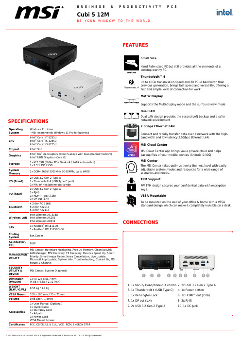
© 2023 Micro-Star Int'l Co.Ltd. MSI is a registered trademark of Micro-Star Int'l Co.Ltd. All rights reserved.SPECIFICATIONSOperating System Windows 11 Home- MSI recommends Windows 11 Pro for business CPU Intel ® Core ™ i7-1255UIntel ® Core ™i5-1235UIntel ® Core ™i3-1215U Chipset Intel ®SoCGraphics Intel ®Iris ®Xe Graphics (Core i5 above with dual-channel memory)Intel ® UHD Graphics (Core i3)Storage 1x M.2 SSD (NVMe PCIe Gen4 x4 / SATA auto switch)1x 2.5" HDD / SSDSystem Memory 2x DDR4 2666/ 3200MHz SO-DIMMs, up to 64GB I/O (Front)2x USB 3.2 Gen 2 Type A1x Thunderbolt 4 (USB Type C port)1x Mic-in/ Headphone-out combo I/O (Rear)2x USB 3.2 Gen 2 Type A 2x RJ451x HDMI™-out (2.0b)1x DP-out (1.4)Bluetooth4.2 (for AC 3168)5.2 (for AX201)5.3 (for AX211)Wireless LAN Intel Wireless AC 3168Intel Wireless AX201Intel Wireless AX211LAN 1x Realtek ®RTL8111H1x Realtek ®RTL8125BG-CG Cooling System Fan Cooler AC Adapter /PSU65WMANAGEMENTUTILITYMSI Center: Hardware Monitoring, Free Up Memory, Clean Up Disk,LAN Manager, MSI Recovery, F3 Recovery, Devices Speed Up, SmartPriority, Smart Image Finder, Noise Cancellation, Live Update,Microsoft App Update, System Info, Troubleshooting, Contact Us, MSI Forum & Channel SECURITY UTILITY &DEVICE MSI Center: System Diagnosis Dimension (WxDxH)124 x 124 x 53.7 mm (4.88 x 4.88 x 2.11 inch)WEIGHT(N.W./ G.W.)0.55 kg / 1.4 kgVESA Mount 100 x 100 mm / 75 x 75 mm Volume0.66 Liter / 1.39 pt Accessories1x User Manual (Optional)1x Quick Guide 1x Warranty Card 1x Adpator 1x Power CordVESA Mount ScrewsCertificatesFCC, CB/CE, UL & CUL, VCCI, RCM, ENERGY STARDual LAN design provides the second LAN backup and a safer network environment 2.5Gbps Ethernet LANConnect and rapidly transfer data over a network with the high-bandwidth and low-latency 2.5Gbps Ethernet LAN.MSI Cloud CenterMSI Cloud Center app brings you a private cloud and helps backup files of your mobile devices (Android & iOS)MSI CenterThe MSI Center takes optimization to the next level with easily adjustable system modes and resources for a wide range of scenarios and needs.TPM SupportFW TPM design secures your confidential data with encryption keys.VESA MountableTo be mounted on the wall of your office & home with a VESAstandard design which can make it completely invisible on a desk.CONNECTIONS1. 1x Mic-in/ Headphone-out combo 3. 1x Thunderbolt 4 (USB Type C)5. 1x Kensington Lock 7. 1x DP out (1.4)9. 2x USB 3.2 Gen 2 Type A2. 2x USB3.2 Gen 2 Type A4. 1x Power botton 6. 1x HDMI™ out (2.0b)8. 2x RJ4510. 1x DC JackNote *Upgrade timing may vary by device. Features and app availabilitymay vary by region. Certain features require specific hardware (seehttps:///en-us/windows/windows-11-specifications).Generated223-11-9,checkforthelatestversionwww.msi.com/datasheet.Theinformationprovidedinthisdocumentisintendedforinformationalpurposesonlyandissubjecttochangewithoutnotice.© 2023 Micro-Star Int'l Co.Ltd. MSI is a registered trademark of Micro-Star Int'l Co.Ltd. All rights reserved.。
超微电脑 AOC-S25G-m2S 用户指南 1.0说明书

User's GuideRevision 1.0AOC-S25G-m2SUser's Guide Revision 1.0 Release Date: March 16, 2017Unless you request and receive written permission from Super Micro Computer, Inc., you may not copy any part of this document.Information in this document is subject to change without notice. Other products and companies referred to herein are trademarks or registered trademarks of their respective companies or mark holders.Copyright © 2017 by Super Micro Computer, Inc. All rights reserved.Printed in the United States of AmericaThe information in this User's Guide has been carefully reviewed and is believed to be accurate. The vendor assumes no responsibility for any inaccuracies that may be contained in this document, and makes no commitment to update or to keep current the information in this user's guide, or to notify any person or organization of the updates. Please Note: For the most up-to-date version of this user's guide, please see our Website at .Super Micro Computer, Inc. ("Supermicro") reserves the right to make changes to the product described in this user's guide at any time and without notice. This product, including software and documentation, is the property of Supermicro and/or its licensors, and is supplied only under a license. Any use or reproduction of this product is not allowed, except as expressly permitted by the terms of said license.IN NO EVENT WILL SUPER MICRO COMPUTER, INC. BE LIABLE FOR DIRECT, INDIRECT, SPECIAL, INCIDENTAL, SPECULATIVE OR CONSEQUENTIAL DAMAGES ARISING FROM THE USE OR INABILITY TO USE THIS PRODUCT OR DOCUMENTATION, EVEN IF ADVISED OF THE POSSIBILITY OF SUCH DAMAGES. IN PARTICULAR, SUPER MICRO COMPUTER, INC. SHALL NOT HAVE LIABILITY FOR ANY HARDWARE, SOFTWARE, OR DATA STORED OR USED WITH THE PRODUCT, INCLUDING THE COSTS OF REPAIRING, REPLACING, INTEGRATING, INSTALLING OR RECOVERING SUCH HARDWARE, SOFTWARE, OR DATA.Any disputes arising between the manufacturer and the customer shall be governed by the laws of Santa Clara County in the State of California, USA. The State of California, County of Santa Clara shall be the exclusive venue for the resolution of any such disputes. Supermicro's total liability for all claims will not exceed the price paid for the hardware product.FCC Statement: This equipment has been tested and found to comply with the limits for a Class A digital device pursuant to Part 15 of the FCC Rules. These limits are designed to provide reasonable protection against harmful interference when the equipment is operated in a commercial environment. This equipment generates, uses, and can radiate radio frequency energy and, if not installed and used in accordance with the manufacturer’s instruction manual, may cause harmful interference with radio communications. Operation of this equipment in a residential area is likely to cause harmful interference, in which case you will be required to correct the interference at your own expense.California Best Management Practices Regulations for Perchlorate Materials: This Perchlorate warning applies only to products containing CR (Manganese Dioxide) Lithium coin cells. “Perchlorate Material-special handling may apply. See /hazardouswaste/perchlorate”.WARNING: Handling of lead solder materials used in this product may expose you to lead, a chemical known to the State of California to cause birth defects and other reproductive harm.PrefacePrefaceAbout this User's GuideThis user's guide is written for system integrators, IT technicians and knowledgeable end users. It provides information for the installation and use of the AOC-S25G-m2S add-on card.About this Add-on CardThe Supermicro AOC-S25G-m2S is a leading edge 25GbE controller. Based on the Mellanox ConnectX®-4 Lx EN chipset with features such as VXLAN and NVGRE, it is backward compatible with 10GbE networks and addresses bandwidth demand from virtualized infrastructures in data centers or cloud deployments. It supports the RoCE specification with CPU offload, delivering low-latency and high-performance over Ethernet networks. Supermicro® Asset Management and thermal detection give an extra layer of controller health management and peace of mind. The Supermicro AOC-S25G-m2S high performance 25GbE adapter solution is an excel-lent choice to enhance network connectivity in data centers and enterprise environ-ments. For more information regarding product support or updates, please refer to our website at /products/nfo/networking.cfm#adapter.An Important Note to the UserAll images and layouts shown in this user's guide are based upon the latest PCB Revision available at the time of publishing. The card you have received may or may not look exactly the same as the graphics shown in this user's guide.Returning Merchandise for ServiceA receipt or copy of your invoice marked with the date of purchase is required beforeany warranty service will be rendered. You can obtain service by calling your ven-dor for a Returned Merchandise Authorization (RMA) number. When returning the motherboard to the manufacturer, the RMA number should be prominently displayed on the outside of the shipping carton, and the shipping package is mailed prepaid or hand-carried. Shipping and handling charges will be applied for all orders that must be mailed when service is complete. For faster service, you can also requesta RMA authorization online (/RmaForm/).This warranty only covers normal consumer use and does not cover damages in-curred in shipping or from failure due to the alternation, misuse, abuse or improper maintenance of products.During the warranty period, contact your distributor first for any product problems.Conventions Used in the User's GuidePay special attention to the following symbols for proper system installation and to prevent damage to the system or injury to yourself:Warning: Important information given to ensure proper system installationor to prevent damage to the components or injury to yourself.Note: Additional information given to differentiate between various modelsor provides information for correct system setup.Naming ConventionSMC Networking Add-on Cards Preface–1 –234 –56 7Character Representation Options1st Product Family AOC: Add On Card2nd Form Factor S: Standard, P: Proprietary, C: MicroLP, U: UIO3rd Product Type/Speed G: GbE (1Gb/s), TG: 10GbE (10Gb/s), 40G: 40GbE(40Gb/s), IBF: FDR IB (56Gb/s), IBQ: QDR IB (40Gb/s) 4th Chipset Model (Optional)N: Niantec (82599), P: Powerville (i350),S: Sageville (X550), F: Fortville (XL710)5th Chipset Manufacturer i: Intel, m: Mellanox, b: Broadcom6th Number of Ports1: 1 port, 2: 2 ports, 4: 4 ports7th Connector Type (Optional)S: SFP+, T: 10GBase-T, Q: QSFP+, C: QSFP28Contacting SupermicroHeadquartersAddress:Super Micro Computer, Inc.980 Rock Ave.San Jose, CA 95131 U.S.A.Tel:+1 (408) 503-8000Fax:+1 (408) 503-8008Email:************************(GeneralInformation)**********************(TechnicalSupport) Website:EuropeAddress:Super Micro Computer B.V.Het Sterrenbeeld 28, 5215 ML's-Hertogenbosch, The NetherlandsTel:+31 (0) 73-6400390Fax:+31 (0) 73-6416525Email:*******************(GeneralInformation)*********************(TechnicalSupport)*****************(CustomerSupport) Website:www.supermicro.nlAsia-PacificAddress:Super Micro Computer, Inc.3F, No. 150, Jian 1st Rd.Zhonghe Dist., New Taipei City 235Taiwan (R.O.C)Tel:+886-(2) 8226-3990Fax:+886-(2) 8226-3992Email:**********************.twWebsite:PrefaceTable of ContentsPrefaceChapter 1 Overview1-1 Overview .........................................................................................................1-1 1-2 Key Features ...................................................................................................1-1 1-3 Specifications ..................................................................................................1-2 General ............................................................................................................1-2 Host Interface ..................................................................................................1-2 Networking Features .......................................................................................1-2 CPU Offload Features.....................................................................................1-3 Overlay Networks ............................................................................................1-3 Hardware-Based I/O Virtualization ..................................................................1-3 Storage Offloads .............................................................................................1-3 Management Features ....................................................................................1-3 Virtualization Features.....................................................................................1-4 Operating System Support ..............................................................................1-4 Remote Boot ...................................................................................................1-4 Operating Conditions ......................................................................................1-4 Physical Dimensions .......................................................................................1-5 Weight .............................................................................................................1-5 Supported Platforms .......................................................................................1-5 Compliance/Environmental .............................................................................1-5 1-4 Similar Products ..............................................................................................1-6 1-5 Optional Parts List ...........................................................................................1-6 Chapter 2 Hardware Components2-1 Add-On Card Image and Layout .....................................................................2-1 2-2 Major Components ..........................................................................................2-2 2-3 SFP28 Ethernet Connections..........................................................................2-3 2-4 NC-SI Header & PCI-E 3.0 x8 Golden Finger ................................................2-4 Chapter 3 Installation3-1 Static-Sensitive Devices ..................................................................................3-1 3-2 Before Installation ...........................................................................................3-2 3-3 Installing the Add-on Card ..............................................................................3-2 3-4 Installing Drivers from the CD-ROM CDR-NIC ...............................................3-3 Windows Drivers .............................................................................................3-4 3-5 Installing Drivers ............................................................................................3-4 Linux Drivers ...................................................................................................3-4 Firmware Update Procedures .........................................................................3-5NotesChapter 1: OverviewChapter 1Overview1-1 OverviewCongratulations on purchasing your add-on card from an acknowledged leader in the industry. Supermicro products are designed with the utmost attention to detail to provide you with the highest standards in quality and performance. For product support and updates, please refer to our website at / products/nfo/networking.cfm#adapter.1-2 Key FeaturesThe key features of this add-on card include the following:• Dual SFP28 Connectors• Low-Profile, Short Length Standard Form Factor• PCI-E 3.0 x8• Mellanox ConnectX®-4 Lx EN Ethernet Controller• Asset Management Features with thermal sensor• Hardware offloads for VXLAN, NVGRE and GENEVE encapsulated traffic • Low latency RDMA over Converged Ethernet (RoCE)• PCI-SIG SR-IOV compliant• Jumbo Frames support up to 9.6kB• PXE support• Erasure Coding Offload• NC-SI for IPMI support• RoHS compliant 6/61-3 SpecificationsGeneral• Mellanox ConnectX®-4 Lx EN dual-port 25Gbps controller • Compact size low-profile standard form factor• PCI-E 3.0 x8 (8GT/s, 5GT/s or 2.5GT/s) interface • Dual SFP28 connectors• Typical power consumption: 8.7WHost Interface• PCI-E 3.0 x8• Message Signal Interrupt (MSI-X)Networking Features• 25G Ethernet Consortium 25 Gigabit Ethernet• IEEE 802.3ae 10 Gigabit Ethernet• IEEE 802.3az Energy Efficient Ethernet• IEEE 802.3ap based auto-negotiation and KR startup • IEEE 802.ad, 802.1AX Link Aggregation• IEEE 802.1Q, 802.1p VLAN tags and priority• IEEE 802.1Qau (QCN) – Congestion Notification • IEEE 802.1Qaz (ETS)• IEEE 802.1Qbb (PFC)• IEEE 802.1Qbg• IEEE 1588v2Chapter 1: Overview • Jumbo frame support (9.6KB)CPU Offload Features• RDMA over Converged Ethernet (RoCE)• TCP/UDP/IP stateless offload• LSO, LRO, checksum offload• RSS, TSS, HDS, VLAN insertion/stripping. Receive flow steering• Intelligent interrupt coalescenceOverlay Networks• Stateless offloads for overlay networks and tunneling protocols• Hardware offload of encapsulation and decapsulation of NVGRE and VXLAN overlay networksHardware-Based I/O Virtualization• Single Root IOV• Multi-function per port• Address translation and protection• Multiple queues per virtual machine• Enhanced QoS for vNICs• VMware NetQueue supportStorage Offloads• RAID offload – erasure coding (Reed-Solomon) offloadManagement Features• Asset Management features with thermal sensor• NC-SI for IPMI SupportVirtualization Features• SR-IOV: up to 256 Virtual Functions• SR-IOV: up to 16 Physical Functions per port• 1K ingress and egress QoS levels• Guaranteed QoS for VMsOperating System Support• RHEL/CentOS• Windows• FreeBSD• VMware• OpenFabrics Enterprise Distribution (OFED)• OpenFabrics Windows Distribution (WinOF-2)Remote Boot• Remote boot over iSCSi• PXE and UEFIOperating Conditions• Operating temperature: 0°C to 55°C (32°F to 131°F)• Storage temperature: -40°C to 70°C (-40°F to 158°F)• Storage humidity: 90% non-condensing relative humidity at 35°CChapter 1: Overview Physical Dimensions• Card PCB dimensions: 14.2cm x 6.89cm (5.6in x 2.71in) (LxW)• Height of end brackets: standard – 12cm (4.725in), low-profile – 8cm (3.15in)Weight• 89.58g (0.1975lb)Supported Platforms• Motherboards with minimum PCI-E 3.0 x8 expansion slot• Server Systems with low-profile or full-height PCI-E 3.0 x8 expansion slots • NC-SI feature is only supported by Supermicro® motherboards with correspond-ing NC-SI connectorsNote: This product is intended to be used with Supermicro server systemsor motherboards as an integrated solution package.Compliance/Environmental•RoHS Compliant 6/6, Pb Free1-4 Similar Products1-5 Optional Parts ListChapter 2: Hardware ComponentsChapter 2Hardware Components2-1 Add-On Card Image and LayoutThe AOC-S25G-m2S LayoutThe AOC-S25G-m2S Image1. Mellanox ConnectX®-4 Lx EN 5. SFP28 Port2 Link LED2. SFP28 Port1 6. NC-SI header3. SFP28 Port27. PCI-E 3.0 x84. SFP28 Port1 Link LED12345672-2 Major ComponentsThe following major components are installed on the AOC-S25G-m2S:1. Mellanox ConnectX®-4 Lx EN Controller2. Dual SFP28 (Small Form Factor Pluggable) Ports3. Two (2) SFP28 Link/Activity LED Indicators4. NC-SI for IPMI supportChapter 2: Hardware Components1. SFP1: SFP28 Port12. SFP2: SFP28 Port23. SFP28 Port1 Link LED4. SFP28 Port1 Link LED2-3 SFP28 Ethernet ConnectionsSFP28 (SFP1/SFP2) ConnectorsTwo small form-factor pluggable (SFP28) optical transceiver connectors (SFP1/SFP2) are located on the add-on card. These SFP28 ports provide Ethernet up to 25GbE network connections. See the layout below for the locations.SFP28 (SFP1/SFP2) Link/Activity LED IndicatorsTwo LAN Link/Activity LED indicators are located at PORT1 LED and PORT2 LED on the add-on card. PORT1 LED is used for the SFP28 SFP1 connector, and PORT2 LED, for SFP28 SFP2 connector. See the table below for the LED states.2-4 NC-SI Header & PCI-E 3.0 x8 Golden FingerNC-SI HeaderA Network-Controller Sideband Interface (NC-SI) header is located at JNCSI1 on the add-on card. Connect an appropriate cable from this header to a motherboard to provide the out-of-band (sideband) connection between the onboard Baseboard Management Controller (BMC) and a Network Interface Controller (NIC) for remote management. For the network sideband interface to work properly, you will need to use a motherboard that supports NC-SI and also need to have a special cable. Please contact Supermicro at to purchase the cable for this header. See the layout below for the location of the JNCSI1 header.PCI-E 3.0 x8 Golden FingerA PCI-E 3.0 x8 Golden Finger is located at JGF1 on the add-on card. Insert this connector into a PCI-E 3.0 x8 slot on a motherboard to use this add-on card. See the layout below for the location.1. NS-CI Header2. PCI-E3.0 x8 Golden FingerChapter 3: InstallationChapter 3Installation3-1 Static-Sensitive DevicesElectrostatic Discharge (ESD) can damage electronic com p onents. To avoid dam-aging your add-on card, it is important to handle it very carefully. The following measures are generally sufficient to protect your equipment from ESD.Precautions• Use a grounded wrist strap designed to prevent static discharge.• Touch a grounded metal object before removing the add-on card from the antistatic bag.• Handle the add-on card by its edges only; do not touch its components, or peripheral chips.• Put the add-on card back into the antistatic bags when not in use.• For grounding purposes, make sure that your system chassis provides excellent conductivity between the power supply, the case, the mounting fasteners and the add-on card.UnpackingThe add-on card is shipped in antistatic packaging to avoid static damage. When unpacking your component or your system, make sure that the person handling it is static protected.Warning: To avoid damaging your components and to ensure properinstallation, be sure to always connect the power cord last, and alwaysremove it before adding, removing or changing any hardware components.3-2 Before InstallationTo install the add-on card properly, be sure to follow the instructions below.1. Power down the system.2. Unplug the power cord.3. Use industry standard anti-static equipment (such as gloves or wrist strap)and follow the precautions on Page 3-1 to avoid damage caused by ESD.4. Familiarize yourself with the server, motherboard, and/or chassis documenta-tion.5. Confirm that your operating system includes the latest updates and hotfixes.3-3 Installing the Add-on CardFollow the steps below to install the add-on card into your system.1. Remove the server cover and, if any, set aside any screws for later use.2. Remove the add-on card slot cover. If the case requires a screw, place thescrew aside for later use.3. Position the add-on card in the slot directly over the connector, and gentlypush down on both sides of the card until it slides into the PCI connector.4. Secure the add-on card to the chassis. If required, use the screw that youpreviously removed.5. Attach any necessary external cables to the add-on card.6. Replace the chassis cover.7. Plug the power cord into the wall socket and power up the system.Chapter 3: InstallationNote: If the FOUND NEW HARDWARE WIZARD screen displays on yoursystem, click CANCEL.3. Click on INSTALL DRIVERS AND SOFTWARE.4. The Install Shield Wizard will start .Follow the prompts to complete the instal-lation.3-4 Installing Drivers from the CD-ROM CDR-NICFollow the steps below to install the drivers needed for your Windows OS support. The controller comes with a driver on the CD-ROM CDR-NIC.1. Run the CDR-NIC. (If you do not have a product CD-ROM, download driversfrom the Supermicro Support Website and then transfer them to your system.)2. When the SUPERMICRO window appears, click on the computer icon next tothe product model.3-5 Installing DriversUse the procedures below to install drivers for the AOC-S25G-m2S add-on card for both Linux and Windows.Linux DriversUse the following procedures to install drivers on the Linux operating system.Installing 25G Drivers for the Linux Operating System1. From the CDR-NIC LAN driver CD, go to the following directory: Mellanox> Linux. You may also go to the Supermicro FTP site at ftp://ftp.super-/Networking_Drivers/CDR-NIC_1.50_for_Add-on_NIC_Cards/Mellanox/25GbE/Linux/.2. Download the Linux driver package file.3. Install the driver by entering the following commands:tar xzvf mlnx-en–<ver>.tgzcd mlnx-en–<ver>./install.shThis installs the Linux drivers to your system.Note: Driver installation may require root privileges.Windows DriversUse the following procedures to install drivers on the Windows operating system.Installing 25G Drivers for the Windows Operating System1. From the CDR-NIC LAN driver CD, go to the following directory: Mellanox> Windows. You may also go to the Supermicro FTP site at ftp://ftp.super-/Networking_Drivers/CDR-NIC_1.50_for_Add-on_NIC_Cards/Mellanox/25GbE/Windows/.2. Choose the desired Windows driver package file.3. Double -click to run and install the executable (.exe ) file in the driver pack-age.4. The Install Shield Wizard will start .Follow the prompts to complete the instal-lation.Chapter 3: InstallationFirmware Update ProceduresUse the following procedures for updating the AOC-S25G-m2S add-on card firm-ware for both the Linux and Windows operating systems.Updating Firmware for the Linux Operating System1. From the CDR-NIC LAN driver CD, go to the following directory: MellanoxFirmware_Tool > Linux. You may also go to the Supermicro FTP site at ftp:// /Networking_Drivers/CDR-NIC_1.50_for_Add-on_NIC_Cards/Mellanox/Firmware_Tool/Linux/.2. Choose the MFT Linux package file and untar the package file.3. Install the package by entering the following command:cd mft–<ver>./install.sh4. Install the firmware by the following commands:mst startmst status *write down the pci_cr0 device name*flint –d <pci_cr0 device name> –i <firmware file name>.bin burnUpdating Firmware for the Windows Operating System1. From the CDR-NIC LAN driver CD, go to the following directory: MellanoxFirmware_Tool > Linux. You may also go to the Supermicro FTP site at ftp:// /Networking_Drivers/CDR-NIC_1.50_for_Add-on_NIC_Cards/Mellanox/Firmware_Tool/Windows/.2. Choose the desired MFT Windows package file.3. Double-click to run and install the MFT package file.4. Open the DOS command prompt and locate the MFT folder.5. Install the firmware by entering the following commands:mst startmst status *write down the pci_cr0 device name*flint –d <pci_cr0 device name> –i <firmware file name>.bin burn(Disclaimer Continued)The products sold by Supermicro are not intended for and will not be used in life support systems, medical equipment, nuclear facilities or systems, aircraft, aircraft devices, aircraft/emergency com-munication devices or other critical systems whose failure to perform be reasonably expected to result in significant injury or loss of life or catastrophic property damage. Accordingly, Supermicro disclaims any and all liability, and should buyer use or sell such products for use in such ultra-hazardous ap-plications, it does so entirely at its own risk. Furthermore, buyer agrees to fully indemnify, defend and hold Supermicro harmless for and against any and all claims, demands, actions, litigation, and proceedings of any kind arising out of or related to such ultra-hazardous use or sale.。
OceanStor Dorado全闪存存储产品手册

4 硬件架构........................................................................................................................................... 9
6.1 硬件规格...................................................................................................................................................................... 22 6.2 软件规格...................................................................................................................................................................... 29
1 产品定位........................................................................................................................................... 1
超云产品介绍.
SC-R6220
2U 双节点 高可用服务器
优势:
1.密度模块化集成服务器 主要部件支持热插拔,每节点集成两个 PCIE全高扩展槽位,提高整机可用性 2.每节点多大6个3.5寸热插拔盘位 如看成1U1节点,每节点有6个盘位的扩 展能力(传统1U服务器的最大硬盘扩展4 个3.5寸)
应用:
此款机型为满足客户对I/O以及存储方 面的要求而设计,对于一些综合性较 强的项目,用于高性能运算行业、视 频、教育等
SC-R3119 SC-R3110 1U SC-R3110-S SC-R5110 SC-R5110-S SC-R3210 SC-R3210-S 2U
1U/非热插拔/6根DIMM单条支持8G最高48G/SATA/单电/5500芯片组 1U/热插拔/6根DIMM单条支持8G最高48G/SATA/单电/5500芯片组 1U/热插拔/6根DIMM单条支持8G最高48G/SATAorSAS/单电/5500芯片组 1U/热插拔/12根DIMM单条支持16G最高192G/SATA/单电or冗余/5520芯片组 1U/热插拔/12根DIMM单条支持16G最高192G/SATAorSAS/单电or冗余/5520芯片组 2U/热插拔/6根DIMM单条支持8G最高48G/SATA/单电/5500芯片组 2U/热插拔/6根DIMM单条支持8G最高48G/SATAorSAS/单电/5500芯片组
SC-R5210
SC-R5210-S
2U/热插拔/12根DIMM单条支持16G最高192G/SATA/单电or冗余/5520芯片组
2U/热插拔/12根DIMM单条支持16G最高192G/SATAorSAS/单电or冗余/5520芯片组
SC-R6110
1U 单节点 UIO服务器
Supermicro

Supermicro® 为服务器和存储解决方案推出新技术美通社旧金山2013年9月10日高性能、高效率服务器、存储技术和绿色计算领域的全球领导者美超微(Super Micro Computer, Inc.) (NASDAQ: SMCI)本周在旧金山举行的2013年英特尔信息技术峰会 (IDF13) 上推出了新的服务器和存储技术,能支持新的 Intel® Xeon®E5-2600/1600 v2 系列处理器(先前称为 Ivy Bridge)。
充分利用了英特尔最新处理器技术的新产品包括FatTwin™、新TwinPro²™系统、12Gb/s SAS3 解决方案、SuperBlade®、Xeon Phi™协处理器解决方案、超级存储(SuperStorage)、超级工作站 (SuperWorkstations) 和嵌入式产品。
另外,美超微的双处理器 (DP)、单处理器 (UP) 主板和最佳机箱服务器 Building Block Solutions®提供更多选择和灵活性,用于构建完美的最佳计算解决方案。
美超微新的更高效系统架构结合英特尔最新处理器,使性能比上一代解决方案改进了40%。
通过一个简单的美超微BIOS 3.0 闪速更新,现有解决方案还为新处理器的更新提供了一种简易方法。
美超微总裁兼首席执行官梁见后 (Charles Liang) 表示:“美超微再一次通过最佳最创新的绿色计算解决方案引领业界。
这些解决方案能为英特尔的新 Ivy Bridge 处理器提供支持。
我们在 FatTwin、TwinPro²和 SAS3 12Gb/s 解决方案上的架构改进实现了最高的计算性能和能源效率,具有最高的 PCI-E、内存和存储 I/O 带宽,从而实现无与伦比的每瓦每美元每平方英尺性能。
我们的新服务器、存储和工作站解决方案结合全球的充分整合与支持服务,能帮助机构在扩大业务时最小化总体拥有成本 (TCO) 和最大化投资回报 (ROI)。
英特尔 服务器主板 S3000AH 说明书

Consignes de sécurité
Lisez attention toutes les consignes de sécurité et les mises en garde indiquées dans ce document avant de suivre toute instruction. Consultez Intel Server Boards and Server Chassis Safety Information sur le Intel® Server Deployment Toolkit 2.0 CD ou bien rendez-vous sur le site /support/motherboards/server/sb/cs010770.htm.
英特尔 ® 服务器主板 S3000AH 用户指南
Hale Waihona Puke vvi英特尔 ® 服务器主板 S3000AH 用户指南
前言
关于本手册
感谢您购买和使用英特尔 ® 服务器主板 S3000AH。 本手册面向负责对该服务器主板进行故障排除、升级和修复的系统技术人员。本 文档概述了主板 / 机箱的功能、提供了附件或您可能需要的其他组件的列表、故障 排除信息以及有关如何在文档标题上添加和更换组件的说明。若要获取本手册的 最新版本,请访问 /support/cn/motherboards/server/S3000AH/
其他信息和软件
如果您需要有关本产品的更多信息,或有关本服务器主板可用附件的信息,请使 用以下资源。可从 /support/cn/motherboards/server/S3000AH/ 获得这些文件。 除非在下表中另有说明,否则,请在该 Web 页屏幕左侧的搜索栏中键入文档名称 或软件名称,然后选择搜索 “本产品”的选项。 表 1. 其他信息和软件
HP StorageWorks EVA 5000 一个RSS坏三块盘过程处理
HP StorageWorks EVA 5000 一个RSS坏三块盘过程处理作者crazyman2046发表于 06月 7, 2011 ·发表评论晚上一个电话,我打车到武汉某高校,发现信息中心已经有不少人了,大家都像热锅上的蚂蚁,原因我倒是知道,他们正用的HP EVA5000不能用了,电子图书、视频、OA都不能用了,有点压力…他们的XX老师跟我大概介绍了一下情况,问我能不能搞得定,我只是说试试看,好给自己台阶下,呵呵看了下设备,吼吼,三块硬盘报红灯,进CommandView EVA,风扇、控制器都报了温度超高,看了一下机房环境,好家伙,没有精密空调、就一个大铁风扇对着设备在吹,这就是他们的散热…Locate了一下Vdisk Group,我晕,坏的两块盘在一个Vraid里,头大ing…其间碰到不少熟人,设备供应商、他们的XX老师,HP的工程师江XX,尝试热拔插了一下,无果…看看日志,大汗….Severity: Undetermined — more information needed to determine severity. A Volume has transitioned to the MISSING state. The affected Volume is identified in the handle field. If the attribute.type field contains the value 1:<UL><LI>The add_handle field contains the identity of the Physical Disk Drive that is associated with that Volume.<LI>The enclosure number, bay number, and rack number where the associated Physical Disk Drive is located are contained in the attribute.value.u32[0], attribute.value.u32[1], and attribute.value.u32[2] fields, respectively.<LI>The internal identification of t hat Volume’s Redundant Storage Set is contained in the attribute.value.u32[3] field.</UL>Otherwise, the content of the add_handle, attribute.value.u32[0], attribute.value.u32[1], attribute.value.u32[2], and attribute.value.u32[3] fields is undefined. The value.ul1 field contains the new state. The value.ul2 field contains the old state. The state values that may be found in the value.ul1 and value.ul2 fields are as follows:<UL><LI>1 = Normal – Volume is present and operating normally<LI>2 = Migrating – Data from this volume is being moved to other storage in this Disk Group<LI>4 = Reconstructing - Volume is inaccessible; redundant data is being regenerated and moved to other storage in this Disk Group<LI>5 = Completing – This previously inaccessible volume has become accessible; data migration is being completed<LI>6 = Reverting – This previously inaccessible volume has become accessible; data is being regenerated<LI>7 = Failed - Volume is not being used in the Disk Group; disk errors are preventing normal usage</UL>A Volume has transitioned to theMISSING state.Volume:6005-08b4-0010-0266-0001-4000-0025-0411; Associated physical disk drive:0000-0000-0000-0000-0000-0000-0000-0000; State: *Reconstructing – Volume isinaccessible; redundant data is beingregenerated and moved to other storagein this Disk Group* –> *Missing -Volume is inaccessible*; Physical DiskDrive identity, location, and RedundantStorage Set internal identificationunavailableEIP05 – Storage System Management Interface Entity State ChangeThe state of a Storage System Management Interface entity has changed.Event Log Packet Event Specific Informationflags (Flags)Flag field bits: 01000011Time has been set on this HSV110 controller: TRUETime has been synchronized with all HSV110 controllers in the Storage System: TRUEEvent sequence number reset occurred: FA LSEEvent reported out of sequence due to Final Event Block reconciliation or lost host event: FALSEEvent requeued following restart or resynchronization: FA LSEEvent reported using LAB code: FA LSEEvent reported by primary HSV110 controller (Note: Not valid until Storage System primary HSV110 controller is elected): TRUESingle power supply HSV110 controller: FA LSErevision – Structure revision number: 2 [0x02]count – Event specific information size in bytes: 180 [0xb4]sequence_number – Sequence number assigned to the event: 6207 [0x183f]sw_version – HSV110 controller software version number string: 3028baselevel_id – HSV110 controller baselevel build string: CR0A3Ectrlr_model_id – HSV110 controller model string: HSV110reporting_ctrlr – Storage System Management Interface Handle of HSV110 controller that reported the event: Noid: 0 IdType: 7 IdLength: 8 UUID: 5005-08b4-0010-7b5d-0000-0000-0000-0000report_time – Time event was reported: Date: 2-Feb-2007 Time: 19:50:13:123report_location – Location of event report call: 2748548 [0x29f084]header (Header Information)** NOTE: The following is part of a UNION with more than one interpretation.You w ill need to determine w hich union value is relevant.** START UNION: ( u – Event Code Union ) **ec (Event Code)eiptype – Event Information Packet Type Code: 5 [0x05]cac – Corrective Action Code: 191 [0xbf]Corrective Action: Evaluate previously reported Device or Device Enclosure events that related to the Physical Disk Drive that is associated with this Volume to determine root cause and corrective action.evnum – Event Number: 6 [0x06]scid – HSV110 Controller Software Component Identification: 9 [0x09]** UNION OR: ( u – Event Code Union ) **value – Event Code Value: 151437061 [0x0906bf05]** END UNION: ( u – Event Code Union ) **revision – Packet revision number: 3 [0x03]type – Packet type: 5 [0x05]count – Number of bytes in packet: 116 [0x74]event_type (Entity and Event type)scmi_object_type – Entity type: 11 [0x0b]scmi_object_event_type – Event Information Packet type: 2 [0x02]value (New entity state)ul1 – Additional information longword 1: 3 [0x03]ul2 – Additional information longword 2: 4 [0x04]Corrective Action: Perform these steps in an attempt to clear the error:evnum – Event Number: 62 [0x3e]scid – HSV110 Controller Software Component Identification: 9 [0x09]** UNION OR: ( u – Event Code Union ) **value – Event Code Value: 155075086 [0x093e420e]** END UNION: ( u – Event Code Union ) **revision – Packet revision number: 2 [0x02]type – Packet type: 14 [0x0e]count – Number of bytes in packet: 116 [0x74]scmi_object_type – Entity type: 6 [0x06]scmi_object_event_type – Event Information Packet type: 12 [0x0c]第一反应,难度很大,先让X老师做备份吧,趁空隙,我出去抽根烟先…跟HP的江XX沟通了一下,暂时无好的解决办法,看来今次要败走麦城了???设备供应商在那里不停的打电话,协调资源,嘿嘿,都忙下吧,不打电话不也事做么?!看资料,找案例,时间在一点点过去,情况很不乐观…唯一的办法就是把Vraid强行online,再图他法一个小时过去了…二个小时过去了…三个小时过去了…终于找到一个办法….这个时候,HP的江XX也从二线那里找到一个办法,我俩一商量,方法一样!报告给X老师,这个方法可行,但有风险,让他自己选择吧挣扎吧,在无尽的深渊里!—三国杀里周瑜语录他说了一句话,搞吧,反正已经这样了….很无奈啊二话不说,开始!连CommandView EVA,进命令行,执行命令如下:xx x-xx x-xx(代码就不说了,哈哈)等待ing…OK,三块盘都online了!赶紧做备份吧,X老师又在那里忙碌着…回顾整个过程,方法很简单,就一个命令而已。
Supermicro在SNW上展示全球唯一一款双处理器存储桥接坞
(YS9 7 . 2B) 支 持 个数 扩 展 到 S .3 R E J 将 l 6个 以上 。在 这两个服 务器 主板封装
中 , 个 都 支 持 双 至 强 5 0 /6 0系 列 每 5050
Sp r co总 裁 兼 首 席 执 行 官 u emi r C al i g表 示 : 们 很 高 兴 为 hr sLa e n “我
提高 。” S pr co系 统 是 S B 新 标 准 的 u emi r B
一
任务关键 型应用 带来具 备双节 点高速
缓存 镜像 优势 的数据 处 理计 算 功能 。 我们 创 新 的 S prS B (YS6 3 S - u e B S .0 6 T 6 R 是一款完全冗余容错 系统 ,可 以 L) 为所 有有源元件提供热插拔封装 。”
( 息来 源 :u e coC mp t ,n . 消 Sp r r o ue Ic Mi r )
一
1 一 6
一
处理器 、 个 D MM 插槽 、 六 I 三个 P I C. E Gn e 2插槽 和 6 b s A (AS20 连 G p S S . S 1 接 。 S .0 6 T 6 R 配 置 了 10W YS62 S .L 20 ( 黄金 级) 高效冗余 电源和冗 余冷 却风 扇 ,是一款 可用性及 可靠性 较高 的且 具备价格优 势的存储系统 。 在 S W 上 展 出 的还有 S pr . N u emi
其 DobeSddSoae ( M) X 存 u l.ie trg T ( 2面 储 ) 及 其 他 6 b sS S(A . 以 G p A S S20 )系
统。
任 何一个与 系统专用 背板 之间 的双重 l 0千兆位 以太 网连接可提供 高速 缓存
Dell PowerVault MD3600i 和MD3620i 存储阵列用户手册

Dell PowerVault MD3600i 和MD3620i 存储阵列用户手册管制型号:E03J 系列和 E04J 系列管制类型:E03J001 和 E04J001注:“注”表示可以帮助您更好地使用计算机的重要信息。
小心:“小心”表示如果不遵循说明,就有可能损坏硬件或导致数据丢失。
警告:“警告”表示可能会导致财产损失、人身伤害甚至死亡。
____________________© 2013 Dell Inc.本文中使用的商标:Dell™、DELL 徽标、PowerEdge™、PowerVault™ 和 OpenManage™ 是Dell Inc. 的商标。
Intel®是 Intel Corporation 在美国和其他国家/地区的注册商标。
Microsoft®、Windows®、Windows Server®、MS-DOS®和 Internet Explorer®是 Microsoft Corporation 在美国和/或其他国家/地区的商标或注册商标。
Red Hat®和 Red Hat EnterpriseLinux® 是 Red Hat, Inc. 在美国和其他国家/地区的注册商标。
SUSE®是 Novell, Inc. 在美国和其他国家或地区的注册商标。
管制型号:E03J 系列和 E04J 系列管制类型:E03J001 和 E04J0012013 - 06 Rev. A02目录1简介 (17)关于本说明文件 (17)Dell PowerVault MD3600i 系列存储阵列包装清单 (17)MD3600i系列存储阵列 (18)Dell PowerVault Modular DiskStorage Manager (18)Dell PowerVault Modular DiskConfiguration Utility (18)可能需要的其它信息 (18)2规划:关于存储阵列 (19)概览 (19)硬件功能 (19)前面板特征和指示灯 (19)背面板特征和指示灯 (22)硬盘驱动器指示灯显示方式 (22)电源设备和冷却风扇特征 (23)电源指示灯代码和功能 (24)目录33规划:RAID 控制器模块 (25)RAID 控制器模块 (25)RAID 控制器模块连接器及功能 (25)RAID 控制器模块 - 其他功能 (27)电池备用单元 (27)存储阵列热关机 (27)系统密码重设 (28)高速缓存的功能和特点 (28)高速缓存镜像 (28)回写式高速缓存 (28)直写式高速缓存 (28)4规划:MD3600i 系列存储阵列术语和概念 (29)物理磁盘、虚拟磁盘和磁盘组 (29)物理磁盘 (29)物理磁盘状态 (30)自我监测分析和报告技术(SMART) (31)虚拟磁盘和磁盘组 (31)虚拟磁盘状态 (31)RAID 级别 (32)RAID 级别的用法 (32)分段大小 (34)虚拟磁盘操作 (34)虚拟磁盘初始化 (34)一致性检查 (35)介质验证 (35)4目录循环时间 (35)虚拟磁盘: 操作限制 (36)磁盘组操作 (36)RAID 级别迁移 (36)分段大小迁移 (36)虚拟磁盘容量扩充 (37)磁盘组扩充 (37)磁盘组碎片整理 (37)磁盘组操作限制 (37)RAID 后台操作优先级 (38)虚拟磁盘迁移和磁盘漫游 (38)磁盘迁移 (38)磁盘漫游 (40)主机服务器到虚拟磁盘的映射 (40)主机类型 (40)高级功能 (41)快照虚拟磁盘 (41)快照库虚拟磁盘 (41)虚拟磁盘备份 (42)虚拟磁盘恢复 (42)同时使用快照和磁盘备份 (43)多路径软件 (43)首选和备用控制器及路径 (43)虚拟磁盘所有权 (44)负载平衡 (44)监视 MD3600i 系列系统性能 (45)目录55配置:概览 (47)用户界面 (47)Enterprise Management Window(企业管理窗口) (48)Array Management Window(阵列管理窗口) (49)6配置:关于存储阵列 (51)带外管理和带内管理 (51)存储阵列 (52)添加存储阵列 (52)设置存储阵列 (53)定位存储阵列 (54)命名或重命名存储阵列 (55)设置密码 (56)查看存储阵列连接 (57)添加/编辑现有存储阵列的注释 (57)删除存储阵列 (58)启用高级功能 (58)显示故障转移警报 (59)更改存储阵列上的高速缓存设置 (59)更改扩展机柜 ID 号 (59)在物理窗格中更改机柜顺序 (60)配置警报通知 (60)配置电子邮件警报 (61)配置 SNMP 警报 (63)电池设置 (65)设置存储阵列 RAID 控制器模块时钟 (66)6目录7配置:使用 iSCSI (67)更改 iSCSI 目标验证 (67)输入相互验证权限 (68)创建 CHAP 机密 (68)启动程序 CHAP 机密 (68)目标 CHAP 机密 (68)适用于 CHAP 机密的有效字符 (69)更改 iSCSI 目标标识 (69)更改 iSCSI 目标搜索设置 (70)配置 iSCSI 主机端口 (70)高级 iSCSI 主机端口设置 (72)查看或结束 iSCSI 会话 (73)查看 iSCSI 统计数据和设置基线统计数据 (73)编辑、删除或重命名主机拓扑 (74)8配置:事件监测器 (75)启用或禁用事件监测器 (75)Windows (75)Linux (76)9配置:关于主机 (77)配置主机访问权限 (77)使用映射选项卡 (78)定义主机 (78)目录7删除主机访问权限 (80)管理主机组 (81)创建主机组 (81)将主机移至其它主机组 (82)删除主机组 (83)主机拓扑 (83)启动或停止 Host Context Agent (84)I/O 数据路径保护 (85)管理主机端口标识符 (86)10配置:磁盘组和虚拟磁盘 (89)创建磁盘组和虚拟磁盘 (89)创建磁盘组 (90)定位磁盘组 (91)创建虚拟磁盘 (92)更改虚拟磁盘修改优先权 (94)更改虚拟磁盘高速缓存设置 (95)更改虚拟磁盘的分段大小 (96)更改 I/O 类型 (97)选择相应的物理磁盘类型 (98)使用自加密磁盘的物理磁盘安全保护 (99)创建安全密钥 (101)更改安全密钥 (104)保存安全密钥 (105)验证安全密钥 (106)解除锁定受保护的物理磁盘 (106)擦除受保护的物理磁盘 (107)配置热备用物理磁盘 (107)8目录热备用和重建 (109)全局热备用 (109)热备用操作 (109)热备用驱动器保护 (109)机柜丢失保护 (110)主机到虚拟磁盘的映射 (111)创建主机到虚拟磁盘的映射 (111)修改及删除主机到虚拟磁盘的映射 (113)更改虚拟磁盘的控制器所有权 (114)删除主机到虚拟磁盘的映射 (114)更改磁盘组的 RAID 控制器模块所有权 (115)更改磁盘组的 RAID 级别 (116)使用 Linux DMMP 删除主机到虚拟磁盘的映射 (116)受限映射 (118)更改虚拟磁盘或磁盘组的 RAID 控制器模块所有权 (119)更改磁盘组的 RAID 级别 (120)存储器分区 (121)磁盘组和虚拟磁盘扩充 (122)磁盘组扩充 (122)虚拟磁盘扩充 (123)使用可用容量 (123)使用未配置的容量 (123)磁盘组迁移 (124)导出磁盘组 (124)导出磁盘组 (124)导入磁盘组 (125)导入磁盘组 (125)目录9存储阵列介质扫描 (126)更改介质扫描设置 (127)暂挂介质扫描 (128)11配置:高级功能—快照虚拟磁盘 (129)制定快照虚拟磁盘计划 (131)制定快照虚拟磁盘计划的一般原因 (131)创建快照计划的原则 (132)启用和禁用快照计划 (132)使用简单路径创建快照虚拟磁盘 (133)关于简单路径 (133)准备主机服务器以使用简单路径创建快照 (134)使用高级路径创建快照虚拟磁盘 (136)关于高级路径 (136)准备主机服务器以使用高级路径创建快照 (137)使用高级路径创建快照 (138)指定快照虚拟磁盘名称 (140)快照库容量 (141)禁用快照虚拟磁盘 (143)准备主机服务器以重新创建快照虚拟磁盘 (144)重新创建快照虚拟磁盘 (145)快照回滚 (145)执行快照回滚的规则和原则 (146)防止失败的快照回滚 (146)MD Storage Manager 的之前版本 (147)10目录启动快照回滚 (147)恢复快照回滚 (147)取消快照回滚 (148)12配置:高级功能—虚拟磁盘备份 (149)虚拟磁盘备份的类型 (150)脱机备份 (150)联机备份 (151)为 MSCS 共享磁盘创建虚拟磁盘备份 (151)虚拟磁盘读/写权限 (152)虚拟磁盘备份限制 (153)创建虚拟磁盘备份 (154)准备工作 (154)虚拟磁盘备份和修改操作 (154)创建备份向导 (155)虚拟磁盘备份失败 (155)首选 RAID 控制器模块所有权 (155)已失效的 RAID 控制器模块 (156)Copy Manager(备份管理器) (156)复制虚拟磁盘 (156)虚拟磁盘备份过程中的存储阵列性能 (158)设置备份优先级 (158)停止虚拟磁盘备份操作 (159)重新备份虚拟磁盘 (159)准备主机服务器以重新备份虚拟磁盘 (159)目录11重新备份虚拟磁盘 (160)移除备份对 (161)13配置:高级功能—升级至高性能层 (163)14配置:Linux 的 Device Mapper多路径 (165)概览 (165)使用 DM 多路径设备 (166)前提条件 (166)Device Mapper 配置步骤 (167)Linux 主机服务器重新引导最佳实践 (171)有关特殊分区的重要命令 (171)限制和已知问题 (172)故障排除 (173)15管理:固件下载 (175)下载 RAID 控制器和 NVSRAM 软件包 (175)同时下载 RAID 控制器和 NVSRAM 固件 (175)仅下载 NVSRAM 固件 (178)下载物理磁盘固件 (180)下载 MD1200 系列扩充模块 EMM 固件 (182)自我监测分析和报告技术 (SMART) (183)介质错误和不可读扇区 (183)12目录16管理:安装阵列组件 (185)推荐工具 (185)前挡板(可选) (186)卸下前挡板 (186)安装前挡板 (186)硬盘驱动器 (187)卸下硬盘驱动器挡片 (187)安装硬盘驱动器挡片 (188)卸下硬盘驱动器 (188)安装硬盘驱动器 (190)从硬盘驱动器托盘中卸下硬盘驱动器 (191)将硬盘驱动器安装到硬盘驱动器托盘中 (193)RAID 控制器模块 (193)卸下 RAID 控制器模块挡片 (193)安装 RAID 控制器模块挡片 (194)卸下 RAID 控制器模块 (195)安装 RAID 控制器模块 (196)打开 RAID 控制器模块 (196)关闭 RAID 控制器模块 (197)RAID 控制器模块备份电池装置 (198)卸下 RAID 控制器模块备份电池装置 (198)安装 RAID 控制器模块备用电池装置 (199)电源设备/冷却风扇模块 (199)卸下电源设备/冷却风扇模块 (199)安装电源设备/冷却风扇模块 (201)控制面板 (202)卸下控制面板 (202)安装控制面板 (203)目录13背板 (204)卸下背板 (204)安装背板 (206)17管理:固件库存 (207)查看固件库存 (207)18管理:系统接口 (209)Microsoft 服务 (209)虚拟磁盘服务 (209)卷影复制服务 (209)19故障排除:存储阵列软件 (211)启动例行程序 (211)设备运行状况 (211)存储阵列支持数据 (214)自动收集支持包数据 (215)检索跟踪缓冲区 (215)收集物理磁盘数据 (217)事件日志 (218)Recovery Guru (219)存储阵列配置文件 (219)查看逻辑关联 (221)14目录查看物理关联 (221)查找节点 (222)使用转到 (223)从无响应的存储阵列情况中恢复 (224)定位物理磁盘 (226)定位扩展柜 (227)捕获状态信息 (228)SMrepassist 公用程序 (229)未识别的设备 (229)从未识别的存储阵列中恢复 (230)启动或重新启动 Host Context Agent 软件 (231)20故障排除:阵列 (233)安全第一—为您和您的阵列着想 (233)排除存储阵列故障启动故障 (233)通信中断故障排除 (233)外部连接故障排除 (233)电源设备/冷却风扇模块故障排除 (234)对阵列冷却问题进行故障排除 (235)扩展机柜管理模块故障排除 (235)RAID 控制器模块的故障排除 (236)硬盘驱动器故障排除 (237)目录15阵列和扩展柜连接的故障排除 (238)对受潮存储阵列的故障排除 (238)对受损阵列的故障排除 (239)RAID 控制器模块的故障排除 (239)状态 (239)无效存储阵列 (239)ECC 错误 (240)PCI 错误 (240)严重情况 (240)非严重情况 (240)21获得帮助 (241)找到您的系统服务标签 (241)联系 Dell (241)文档反馈 (241)索引 (243)16目录简介注:除非另行指定,否则 MD3600i 系列均表示 Dell PowerVault MD3600i 和Dell PowerVault MD3620i 存储阵列。
美超微新1U-2U Ultra SuperServers提供灵活高带宽I-O解决方案

美超微新1U/2U Ultra SuperServers提供灵活高带宽I/O解决方案高性能、高效率服务器、存储技术与绿色计算领域的全球领导者美超微电脑股份有限公司 (Super Micro Computer, Inc.)(NASDAQ: SMCI)发布新的1U/2U超级系列SuperServers,在4x 40G QSFP+、10G SFP+、10GBASE-T和1G端口配置下具有更加灵活的高带宽I/O端口。
新款服务器还通过一个创新气流优化的冷却架构和1000W冗余钛金级电源、支持高达160W 及以上功率的双英特尔®至强®处理器E5-2600 v3的高效(96%+)数字电源提高了能效。
此外,内存性能增强了14%,新解决方案还采用了最新的NVMe技术。
图片- /prnh/20150125/171159与现有的固态硬盘(SSD)技术相比,新NVMe技术支持的Ultra服务器能够使延时性能提高七倍,带宽提升六倍。
美超微是首家提供真正热插拔NVMe驱动功能的公司,并将很快为1U机架式服务器提供10倍热插拔NVMe驱动支持,为2U机架式服务器提供2倍、4倍、8倍或者高达24倍热插拔NVMe支持。
Ultra系列服务器建立在美超微Building Block Server®基础之上,配有750W、1KW以及即将推出的1.6KW或2KW高效率数字电源,支持英特尔®至强®Phi™协同处理器和NVIDIA® Tesla® GPUs,能够进行大规模平行处理或者满足任何应用需求。
此外,Ultra SuperServers采用无工具设计,配置效率高且易于维护。
美超微总裁兼首席执行官梁见后( Charles Liang )表示:“美超微的Ultra系列SuperServers提供市面上最灵活的高带宽I/O解决方案,并且将最先进的计算与网络技术集成在一个架构中。
阿尔法窝 ES 储存器 1U 高亮特点说明书

What is it?Alphacool ES Reservoir 1UHighlightsThe Alphacool ES Reservoir 1U is a combination of expansion tank and pump top that was developed di-rectly for use in 1U server racks. It can be mounted directly on radiators or separately. With 6x IN andone OUT, the expansion tank also offers extensive options for tubing.- part of the Enterprise Solutions Series - extreme small form factor - reservoir integrated - pump is fully enclosedArticle textThe Alphacool ES reservoir for DDC pumps is specially designed for 1U server racks. The reservoir is extremely compact and integrated pump top for the DDC pump allows for extremely high pump perfor-mance. The large reservoir is more than sufficient for a liquid cooling loop in a 1U server rack.How Can I Connect the Reservoir?The reservoir offers a total of seven G1/4" connections, 1x OUT and 6x IN. The connection possibilities are distributed on all sides. One IN is located on each side. Additionally, there are two IN on the top side which are mainly used for filling. One IN can be used directly for filling, while the second IN is used to allow air to escape more easily during the process. Due to the many connection possibilities, various mounting options are possible.What Mounting Options Does the Expansion Tank Offer?On the bottom and on the sides, there are mounting holes that allow you to mount in the standard 2.5" hard disk space. As with a 2.5" SSD, the reservoir can be screwed to the bottom or the sides. If there is no corresponding mounting space available, a Velcro pad is also included. Both parts of the Velcro tape have an adhesive surface allowing you to attach one part to the case and one part to the reservoir and then simply sticking them together. The assembly is finished and it is also easily removed if needed. Direct Radiator Mounting Is Possible!The scope of delivery includes a double nipple fitting with which allows the reservoir to be screwed di-rectly to a radiator of the Alphacool NexXxoS series. For 1U housings Alphacool offers special 40 mm radiators from the NexXxoS X-Flow series. With these radiators, the reservoir can be mounted via the double nipple on the side or in front of the radiator. This saves a lot of space instead of connecting the reservoir with a longer hose.Installation of the PumpThe installation of the DDC pump is very easy. The O-ring is put on and then the pump is placed into the pump top and fixed with four screws. Please note that a DDC version with the original Laing pump hous-ing is installed. Other pump housings may be larger and may not fit the reservoir.The Alphacool ES Reservoir 1U - DDC version is an extremely compact expansion tank especially for 1U server racks with extensive connection and mounting options.。
超窄3.5英寸双面磁盘驱动器说明书
YD-702J-6637JProduct SpecificationsSUPER SLIM 3.5 FLOPPY DISK DRIVE12.7mm HEIGHT2.0/1.6/1.0 MB 3MODE TYPEFDZ-529022 REV.A4FDZ-529022 REV.A4Revisions Month/ Year RevisionReason for RevisionRevised Pages Oct., 1999Rev. A 1st editionJan., 2000Rev. A1Delete optional connector (NON-ZIF TYPE)P11Apr., 2000Rev. A2Screw fastening torque changeP13Jul., 2001Rev. A3Additional of specification (Non operating shock)P3,4Aug, 2003Rev. A4Added to comments on restrictions of liability and high safety use. Drawing adjustment.P2,12This product specification describes the YD-702J series double-sided, 3.5 floppy disk drive for portable applications.(1) I n this manual, the term “drive” refers to the YD-702J series double-sided,3.5 floppy disk drive. The term “disk” refers to the 3.5 floppy disk.z This specification may be revised without prior notice.Make sure to check the revision number when placing an order.zUnauthorized duplication of this document is prohibited.For the usage of this product for High Safety useThis product is assumed for general uses, such as an object for general office work, personal and home use, and is not designed or manufactured supposing for High safety use. Make sure not to use this product without taking measures to ensure the safety required for the high safety use.High Safety Use means the use that requires extremely high security (see examples), and that accompanies a serious danger for the life and body directly, if security cannot be ensured.*Nuclear control, airplane flight control, air traffic control, mass transportation operation control, life support,weapon launch control, etc.This product specification is subject to change without notice.Chapter 1. IntroductionThese specifications pertain to the YD-702J series of 3.5”, super slim, 5-volt single power supply, double-sided micro floppy disk drives.The YD-702J series has been designed for 3.5 (90mm) floppy disk.1. Super-sliminessWith a 12.7mm height and a weight of 158g, the YD-702J drive is approximately half the size and weight of current 3.5 floppy disk drives (compare with Y-E DATA’s YD-702D).2. Low Power ConsumptionA standard power consumption of 1.15W during operation and 15mW during standby allows for battery-driven operation.3. High PerformanceA direct drive brush less motor is used to guarantee high performance.4. Shock ResistanceShock-absorbing teeth built directly into the head carriage assembly have raised shock resistance to 980.7m/s2 {100G}(11ms half-sine wave)and 2157.5m/s2 {220G}(2ms half-sine wave).FDZ-529022 REV. A4FDZ-529022 REV.A4- 4 -Chapter 2. Product Specifications 2.1 Performance Item 2.0MB Mode 1.6MB Mode 1.0MB Mode Capacityz Unformatted z Formatted 1)Sectors/Track 2)Sectors/Track 3)Sectors/Track Recording Density (bits/mm){BPI}Track Density (tracks/mm){TPI}Cylinders Tracks Encoding Method Rotational Speed (min -1){RPM}Transfer Rate Latency(Average)Access Time z Average z Track to Track z Settling Time z Turn Around Time Motor Start Time2.0Mbytes 18: 1474.6kBytes 686.4{17434}5.315{135}80 Cylinders 160 Tracks MFM 300500 kbits/s 100 ms 94 ms 3 ms 15 ms 4 ms 0.5sec 1.6Mbytes 26: 1025.0kBytes 15: 1182.7kBytes 8: 1261.6kBytes 558.4{14184}5.315{135}77 Cylinders 154 Tracks MFM 360500 kbits/s 83 ms 91 ms 3 ms 15 ms 4 ms 0.5 ms 1.0Mbytes 16: 655.4kBytes 9: 737.3kBytes 5: 819.2kBytes 343.2{8717}5.315{135}80 Cylinders 160 Tracks MFM 300250 kbits/s 100 ms 94 ms 3 ms 15 ms 4 ms 0.5sec Table 2.1 Performance2.2 Physical Specifications 2.3 Reliability and Maintenance MTBF PM*MTTR Component Life Error Rates ●Soft Errors ●Hard Errors ●Seek Errors 30,000POH None 30 minutes 5years or 20,000POH 1 per 109 bits read 1 per 1012 bits read 1 per 106 seek operations Table 2.3 Reliability * Preventive maintenance Note: Non-operating shock and vibration values are the same as above with or without disk in the drive.Signal Connector DC Power Requirements Power Consumption Environment● OperatingTemperature Relative Humidity Maximum Wet Bulb Vibration Shock● Non operatingTemperature storageTransportationRelative HumidityVibrationShockMechanical DimensionsWidthHeightDepthWeightSafety ApprovalsFFC Connector1mm pitch, 26pinIncluding DC power lineRefer to figure 4.2Refer to Table 3.8.1.15W TYP5°C to 50°C (note 1)20% to 80%29°C 9.8m/s 2{1G}(10-200Hz)4.9m/s 2{0.5G}(200-500Hz)58.8m/s 2{6G}(11ms half-sine wave)-40°C to 60°C -40°C to 65°C No condensation 19.6m/s 2{2G}(10-500Hz)980.7m/s 2{100G}(11ms half-sine wave)2157.5m/s 2 {220G}(2ms half-sine wave)96.0mm 12.7mm 130mm 158g(TYP)UL, CSA, TÜV, CE Mounting Recommendations See figure 5.2Table 2.2 Physical SpecificationsNotes:1. Depending on the mounting orientation, drive performance may be affected at maximum temperatures. Please mount the drive to ensure that the temperature at the diskette jacket does not exceed that outlined in the media specifications.FDZ-529022 REV.A4- 5 -Chapter 3. InterfaceRefer to figure 3.6 for all interface connections.3.1 Interface Signals 3.1.1 Input signalsThe YD-702J has input lines as shown below.All lines are active (true) when “Low”(1)(2)(3)(4)(5)(6)(7)(8)DRIVE SELECT 0MOTOR ON DIRECTION SELECT STEP WRITE DATA WRITE GATE SIDE ONE SELECT MODE SELECT Table 3.1 Input Signals 3.1.1.1 DRIVE SELECT 0With the exception of the MOTOR ON signal, all the interface signals become valid when the DRIVE SELECT signal is set to low level.3.1.1.2 MOTOR ONWhen “MOTOR ON” is “Low” and a disk is inserted into the drive, the spindle motor will start. The spindle motor operates regardless of “DRIVE SELECT”. However if the disk is removed, the spindle motor will immediately stop.3.1.1.3 DIRECTION SELECTThis line determines the direction of read/write heads movement when the “STEP” line is pulsed.“HIGH” level Out(away from the center of the disk)“LOW” level In(toward the center of the disk)Table 3.2. DIRECTION SELECTAny change on this line must be done at least 1 usec.before the leading edge of the step pulse, and at least 1 usec. after the trailing edge of the step pulse.Refer to figure 8 for the timing information.3.1.1.4 STEPThis signal moves the read/ write heads in the direction defined by the “DIRECTION SELECT” signal.The access motion is initiated on each “LOW” to “HIGH”level transition, in other words, with the trailing edge of the signal pulse. In a seek operation, an 18 ms delay following the last “STEP” pulse is required for settling time before any read/write operation can be initiated.After direction switching, minimum 4 ms delay is required before initiating the next seek operation.Change of step pulse period during seek operation is not recommended for seek error.Refer to figure 1 for timing.Fig.3.1 Step3.1.1.5 WRITE DATAThe “WRITE DATA” line provides the data to be written on the disk. Each transition from “High” to “Low” onthe line causes the current through the read/ write heads to be reversed, thereby writing a data bit. This line is enabled when the “WRITE GATE” line is “Low” active.Refer to figures 3.2 and 3.11 for the timing information.FM RecordingMFM RecordingFig.3.2 WRITE DATA Notes:1.2.0 / 1.6 MB 1.0MB a 2.00us±10ns 4.00us±20ns b3.00us±15ns 6.00us±30ns c4.00us±20ns 8.00us±40ns d 150-1100ns 150-2100ns2. All timings indicate the values without write pre-compensation.3. The write precompensation value in 2.0MB is 125 ns on all tracks, and in other capacities as below:Capacity 2.0MB 1.6MB 1.0MB WPC value 125 ns 0-125 ns 0-250 ns4. The recommended condition during read operation is to not input “WRITE DATA”.3.1.1.6 WRITE GATEA “Low” active level on this line allows “WRITE DATA” to be written on the disk. A “High” inactive level enables read data logic and stepping logic. Refer to figure 3.11 for the timing information. Activation of “DRIVE SELECT”and “MOTOR ON”, changing “SIDE ONE SELECT” and/or activation of “STEP” must be delayed at least the values indicated (see the following READ RECOVERY TIME table 3.3) following deactivation of “WRITE GATE”because the erase heads remain active during this period.Capacity 2.0MB 1.6MB 1.0MB RRT MIN 650 us 590us 1000 us Table 3.3 Read Recovery TimeC C C Cdca C DDDC ca b dC: Clock D: Data3msMIN1usMINFDZ-529022 REV.A4- 6 -3.1.1.7 SIDE ONE SELECTThis line defines which side of a two sided disk will be used for reading or writing. A “High” level on this line selects the read/write head on side 0 surface on the disk. A “Low”level on this line selects the read/write head on the side 1surface. When switching heads, a 100 usec. delay is required before any read or write operation can be initiated.3.1.1.8 MODE SELECTThe YD-702J series has an internal circuit that performs the switching of the drive’s three (2.0/1.6/1.0MB) capacity modes.Please refer to below.Capacity Mode Switching Method Specifications3 Mode(2.0/1.6/1.0MB)Automatic Switching withInterface SignalThe drive is in 1.0MB mode with double density media and independent of the “MODE SELECT” signal (J1-13).If high-density media is inserted with the “MODE SELECT” signal is “LOW” when the drive is in 1.6MB mode.If high-density media is inserted with the “MODE SELECT” signal is “HIGH” when the drive is in 2.0MB mode.Table 3.4 MODE SELECT Notes:(1)To switch capacity mode is effected by a signal level on the “MODE SELECT” signal.(2)It is necessary to wait 0.5 sec. before executing a read/write operation after motor revolution speed is switched for capacity mode change. :READ DATA”, ”INDEX”, signals are inhibited to output during this term.Fig.3.3 Capacity Mode SwitchingFDZ-529022 REV.A4- 7 -3.1.2 Output signalsOutput signals are shown below. All lines are active when the “DRIVE SELECT” signal is “Low”.(1)TRACK 00(2)INDEX(3)HD(High: HD)(4)WRITE PROTECT (5)READ DATA (6)READY(7)DISK CHANGE Table 3.5 Output Signals 3.1.2.1 TRACK 00A “Low” active level on this line indicates that the read /write heads are positioned at track 00(the outermost track). The line goes “High” inactive when the heads are positioned elsewhere. Refer to Fig.3.8 for the timing information.3.1.2.2 INDEXOne index pulse is output at each revolution of the disk when the drive is ready to read/write. Normally this signal is at “High” level, and makes the transition to “Low” level when a pulse is generated. This signal is inhibited to output during seek and not ready. The controller should detect “INDEX” with the leading edge of the transition rather than with the signal level.Fig.3.4 INDEX3.1.2.3 WRITE PROTECTA “Low” active level on this line indicates that a disk with a write protect notch is loaded. During normal operation the drive will prevent writing when a protected disk has been inserted.3.1.2.4 READ DATAThis line provides the “READ DATA”(clock and data together) as detected by the drive electronics. Normally this signal is “High” level and becomes “Low” level for each flux reversal. The transition from “High” to “Low”level should be used for separation of data bits from read data. This signal is inhibited to output during seek and not ready. The different value between the leading edge of each bit pulse and its nominal position is below note 2.Timing characteristics are shown in figure 3.10.FM RecordingMFM RecordingFig.3.5 READ DATANotes:1.2.0/1.6MB 1.0MBa 2.00us NOM 4.00us NOM.b 3.00us NOM. 6.00us NOM.c 4.00us NOM.8.00us NOM.d 150-1100ns150-2100ns2.Capacity 2.0/1.6MB 1.0MB Difference±350ns±700ns3.1.2.5 DISK CHANGEThe “DISK CHANGE” signal indicates that the disk has been removed. This signal becomes “Low” after power has been applied to the drive and the disk has been removed.This signal remains active until the following conditions have satisfied:(1) A disk is correctly inserted;(2) A drive has been selected and a step pulse has been applied.C D C Cdca C DD D C ca b dC: Clock D: Data(166.7ms ±1.5%)200.0ms ±1.5%1~8msFDZ-529022 REV.A4- 8 -Fig.3.6 Interface Connection 3.1.3 Interface CircuitsThe YD-702J series uses open collector drivers as output line drivers, and TTL level gates as input line receivers.The input of each receiver is terminated in 20 k ohms pulled up to Vcc (+5V). Input/output circuit electrical specifications are as shown below.Inactive “High” Level 2.0 V to Vcc Active “Low” Level 0 to 0.8 V Input Impedance 20 k ohms pulled up to Vcc Table 3.6 Input Circuit Electrical Specifications Inactive “High” Level Open Active“Low” Level0 to 0.4VSink current: 6mA MAXTable 3.7 Output Circuit Electrical SpecificationsThe illustration below shows the recommended controller interface circuit.Fig 3.7 Interface CircuitTo connect the drives to the host system via a daisy chain,an FFC (Flexible Flat Cable) connection cable must be used. Refer to section 4.1.2 for this cable’s specifications.Also, because an FFC cable (as opposed to a conventional flat cable) is used, 2 FFC connectors are required in the host system.Caution: In the case where multiple drivers are connected in a daisy chain, it is forbidden to leave any drive unpowered.Each drive should receive power from the host system.3.1.3.2 Host System Terminal ResistorBecause the line driver of the drive is an open collector output, please use a terminal resistor (1k~5.6k Ω) on the host system side.Cable length 500mm MAXFDZ-529022 REV.A4- 9 -3.1.4 Timing3.1.4.1 Track 00 TimingFig.3.8 Track 00 Timing 3.1.4.2 Seek TimingIn order to reduce the peak current, we recommended that no seek operation be performed for 0.2 secondsafter motor start. Figure 3.9 shows the preferred timing.Fig.3.9 Seek Timing3.1.4.3 Read TimingNote:Capacity 2.0MB 1.6MB 1.0MB X us MIN 650 us 590 us 1000 usFig.3.10 Read Timing 3.1.4.4 Write TimingNote:Capacity 2.0MB 1.6MB 1.0MB X us MIN 650 us 590 us 1000 us Y us MAX4 us 4 us 8 usFig.3.11 Write TimingDIRECTlO STEP TRACK 002.9ms MAX 17us MAXMOTOR ONONDRlVEDIRECTlON SELECTSTEP0.5us MIN 1us MIN1us MIN1us MIN200 ms MIN3 ms MIN4 ms MIN3 ms MINONDRlVEMOTOR ONSTEPSIDE ONEREAD DATA (VALID)WRITE GATE500 ms MAX 18 ms MAX 100us MAX 100us MAXXus MAXVALIDVALIDONDRlVEWRITE GATEWRITE DATAMOTOR ONSTEPSIDE ONE500 ms MIN 18 ms MINYus MAX Yus MAX100us MIN Xus MINXus MINXus MINFDZ-529022 REV.A4- 10 -3.2 Power Interface3.2.1 P ower Supply Specifications VoltageOperating Mode TYP(mA)MAX(mA)Stand by 35Read 230350Write 230350+5VDC ±10%(Ripple: 100 mVp-p MAX)Seek550750Motor Start650740Peak Seek550830Table 3.8 Power Supply SpecificationsNotes:(1) “MAX” values reflect measurement taken at maximum voltage; “TYP” values reflect measurement taken at nominal voltage.(2) “Standby” refers to the state where all input signals are inactive.(3) “Read” and “Write” refer to the state where the heads are at track 40, side 1 and the In Use Lamp is on.(4) “Seek” refers to the average current with the drive continuously seeking at 3 ms and the spindle motor rotating.(5) When the spindle motor starts, “Motor Start” current will continue for approximately 200 ms.(6) Peak current of “Seek” refers to the state of maximum seek current when the spindle motor is rotating and the heads are stepping at 6 ms.The above specifications must be met when voltages are measured at power connector on PWB.3.2.2 C urrent Waveform5 V DC (TYP)MOTOR STARTSTAND BYSTAND BYSEE READ READ WRlTE[mA]1000800600400200Fig.3.12 Current WaveformChapter 4. Physical InterfaceThis drive is connected to the host system by one type of connectors.The cable connections are illustrated in figure4.1 Signal Connector and cable (J1/P1)4.1.1 J1 Signal ConnectorThe J1 Signal connector is 26pin FFC connector located at the rear of the drive.Standard:ZIF TYPE (SMK Model CFP5126-0501 or equivalent)Unit: mm Fig 4.2 J1 Signal Connector Dimensions 4.1.2 P1 CableA P1 cable connector is used to connect the J1 signal connector to the system interface.Recommended PartsFFC: •Sumitomo Electric Industries LTD’s ”sumi”card SMCD-26•Eikura Communication’s ET-C100-264.1.3 Frame GroundThe internal circuit ground on the PWB has beenconnected with the frame for shielding purposes. Theframe ground of the system will be connected to thesignal ground through the drive when the drive isinstalled into the system.The frame ground and signal ground of the systemhave to be connected except the drive.Otherwise the drive ought to be floated from the frameground of the system.4.2 Connector Pin Assignments4.2.1. Signal Connector Pin AssignmentsSignal Pin#Signal name24678910111213141618202224261,3,515~25(Odd No. pins)INDEXDRIVE SELECT 0DISK CHANGEN.C.READYHD (High: HD)MOTOR ONN.C.DIRECTION SELECTMODE SELECTSTEPWRITE DATAWRITE GATETRACK 00WRITE PROTECTREAD DATASIDE ONE SELECT+5VGNDTable 4.1 Signal Connector Pins4.3 TerminatorsAll input lines on the drive are terminated with non-removable resistors of 20k ohms.Hostsystem Drive 0Fig 4.1 Cable ConnectionsDrive 1P1J1P1J1Chapter 5. DiagramsFig.5.1 Mechanical DimensionsRecommended angle of the drive when the drive is installed is less than +30 degrees.Fig.5.2 Recommended Mounting21+/-0.490+/-0.210.91.712.7+/-0.22.5+/-0.2M2.6 tapped holes for installation depth 2.2Max(Each side x2)Eject buttonDisk LED(OPTION)2632.51196+/-0.2126+/-0.4Eject button position5+/-1 (Disk inserted)0.6+/-0.6 (Disk ejected)21+/-0.490+/-0.22.5+/-0.22729.696+/-0.2Signal connector(units:mm)Pin 1insertion32.5NOTES 1) GENERAL TOLERANCES ARE +/-0.596+/-0.2Tapping FaceZ( x4)Z 90.7+/-0.53.6+/-0.53.6+/-0.593.4+/-0.52.6+/-0.53.6+/-0.545.45+/-0.345.45+/-0.396+/-0.221+/-0.42.5+/-0.55+/-0.50+/-0.345.1 Caution on Mounting1)Mounting screws should be tightened by 0.2Nm{2kgf-cm} in torque.2)Mounting bracket is recommended not to make contact with the drive except the mounting spots, and should notbe designed that any portion on the drive except the mounting spots is pressed and/or crushed.3)Recommended to fasten the drive at 3 mounting spots with screws (4 spots available).4)Mounting bracket should be provided structure to absorb strain.5)The drive should be separated or shielded from noise sources. Do not strain the drive. Do not install the drive inlarge electromagnetic fields. Otherwise, failure may result.Not to exceed 5 mm Depth to be at exceed 0.5 mmSide mounting plateSide Mounting(Example 1)FDDFDDFDDThickness not exceed 1 mm Depth to be at exceed 0.5 mmSide mounting plateThickness not exceed 1 mmSide mounting plateThickness not exceed 1 mmFig.5.3 Caution on Mounting Washer dimensionsDiameter not to exceed 5 mm Thickness to be at least 0.5 mmNot to exceed 5 mm Side Mounting(Example 2)Side Mounting(Example 3)5.2 Caution on handling1)Strong vibration and shock can damage the drive. Itmay cause an error. Do not use or store the drive under such conditions.2)We recommend handling the drive on side frame,portion of mounting spots, of the drive as well as possible. If you handle like pressing the top or the bottom of the drive, it may cause damage of heads and PWB.3)Do not disassemble the drive by yourself because ofan adjusted product. If you do so, we can not assure you of adjusted accuracy.Chapter 6. Other Functional Characteristics6.1 Standby ModeThe YD-702J includes standby mode to reduce the load on the host system power supply when the drive is not actually in use. When the spindle motor stops, power to the read/write and spindle motor control systems is cut off, and power to the stepper is cut off when the stepper is not seeking.As a result of this built in power conservation, when all the interface input signals are inactive, typical drive power consumption is 15mW.6.2 In UseThe IN USE lamp will turn on when DRIVE SELECT is at low level and turn off when it is high.6.3 Mask Function“READ DATA” and “INDEX” signals are inhibited to output during seek (includes 18 ms MAX after the last step pulse) and not ready (500 ms MAX after motor start).6.4 Automatic Motor On/OffWhen the disk is inserted or removed, the spindle motor is controlled as follows:1)When the disk is inserted, the spindle motor willstart to rotate regardless of the “MOTOR ON” signal condition. The spindle motor will stop approximately 400 ms later if the “MOTOR ON” signal is not active, but will continue to rotate if it is active.2)When the disk is removed, the spindle motor willstop.。
当12核猛龙遇上超级迷你雕

当12核猛龙遇上超级迷你雕作者:来源:《电脑报》2020年第32期技嘉B550I AORUS PRO AX定位就是一款mini-ITX豪华版B550,同时拥有B550的次旗舰规格与mini-ITX板型的迷你身材,非常适合发烧级玩家打造性能級迷你主机,同时小巧的身材也可以适配各种MOD主机,发挥玩家的创造力。
之所以技嘉B550I AORUS PRO AX能够稳定支持发烧级的锐龙9 3900X处理器,就是因为它在供电设计方面完全向大板旗舰看齐。
它搭载了8相(6+2)直出式供电,相比倍相和并联方案,能够提供更高的响应速度。
MOS管部分,它搭载了来自Intersil的ISL99390整合式芯片,拥有更低的内阻和更强的供电能力,单颗能够承载高达90A的电流负荷,因此总输出能力达到了720A,足以满足第三代锐龙旗舰级处理器的供电需求,同时也为下一代 ZEN3锐龙处理器做好了准备。
PWM芯片部分,它采用了RAA229004(ISL229004)数字PWM控制器,这是一颗原生8相的PWM控制器,正好与主板的8相直出式供电相对应,电压控制更加精准可靠。
除了供电规格强悍,技嘉B550I AORUS PRO AX还采用了2盎司铜8层PCB,相比传统消费级的4层PCB设计来说,具备更高的电气性能,能为主板提供更好的稳定性和散热能力,从而确保发烧级处理器稳定工作。
此外,对于mini-ITX主板来说,工作温度和散热能力也非常重要。
技嘉B550I AORUS PRO AX的VRM散热装甲也采用了新一代设计方案,M.2散热装甲、VRM散热器通过两组高效热管进行连接,配合额外散热开槽并辅以高效导热垫,散热装甲的厚度也大大提升,从而提供了超强的散热能力,保证在超频状态下,VRM电路的温度也保持在安全范围内。
特别值得一提的是,这次B550I AORUS PRO AX的M.2散热装甲非常人性化。
在很多主板上,主板M.2散热装甲与NVMe固态硬盘自带的散热装甲是冲突的,只能二选一,但技嘉B550I AORUS PRO AX很好地解决了这个问题,它提供的堆叠式散热装甲可以与M.2散热装甲共存,主板散热装甲整体视觉效果完全不受影响。
Supermicro(R)新一代计算解决方案提供突破性95%+效率
Supermicro(R)新一代计算解决方案提供突破性95%+效
率
佚名
【期刊名称】《电脑与电信》
【年(卷),期】2012(000)003
【摘要】Supermicro新一代基于至强E5处理器的计算解决方案利用数字开关电源供应器技术提供突破性95%+效率先进的电源模块在广泛的负载范围内提供最
高水平的效率并提高功率因数校正
【总页数】1页(P14-14)
【正文语种】中文
【中图分类】TN86
【相关文献】
1.应用材料推出突破性的SmartMOVe系统为客户提供无线硅片管理解决方案 [J],
2.BOBST推出重大突破性产品和解决方案为加工商和品牌所有者提供新商机 [J],
3.AItera提供突破性FPGA电源解决方案 [J],
4.恩智浦携手天碁科技为中国市场提供突破性TD-SCDMA解决方案 [J],
5.LSI与Supermicro合作提供端对端6Gb/s SAS解决方案 [J],
因版权原因,仅展示原文概要,查看原文内容请购买。
u盘主控方案
u盘主控方案近年来,随着数据存储需求的不断增加,U盘已经成为人们生活中必不可少的存储设备。
在市场上,我们可以找到各种各样的U盘产品,而这些产品的实际性能和稳定性很大程度上取决于其中的主控方案。
一、主控芯片的重要性U盘的主控芯片是控制数据的传输和存储的核心部件。
它负责处理与电脑之间的数据通信、芯片内部的数据管理和存储单元的控制等关键任务。
好的主控芯片能够提供更稳定的数据传输速度和更可靠的数据存储,而较差的芯片则可能导致数据丢失、传输速度慢甚至U盘无法正常使用。
二、常见的1. SMI(铭矽)铭矽是国内外著名的U盘主控方案厂商之一,它的主控芯片性能稳定可靠,被广泛应用于许多知名品牌的U盘产品中。
铭矽的主控芯片在性能方面表现出色,可以提供高速的数据传输和稳定的读写速度。
同时,铭矽主控方案还支持多种操作系统和文件系统,能够适应不同用户的需求。
2. SM3257SM3257是另一家知名的主控方案厂商。
它的主控芯片具有较高的性能和兼容性,广泛应用于U盘产品中。
SM3257主控芯片支持高速USB3.0接口,能够提供更快的数据传输速度。
此外,SM3257还具备低功耗、低热量等优点,能够有效延长U盘的使用寿命。
3. Alcor Micro(阿尔克)阿尔克主控芯片是国内领先的主控方案厂商之一。
其主控芯片凭借出色的性能和可靠性,被广泛应用于各类U盘产品中。
阿尔克主控方案支持高速USB3.0和USB2.0接口,能够满足不同用户对速度和稳定性的需求。
此外,阿尔克还提供完备的数据加密和安全保护功能,确保用户的数据得到有效的保护。
三、主控方案选择的注意事项1. 根据需求选择合适的主控方案不同用户对于U盘的需求各不相同。
有些用户注重速度,希望能够尽快传输大量的数据;而有些用户则更加关注数据的安全性,希望通过加密等功能保护自己的隐私。
在选择主控方案时,用户应根据自己的需求,选择合适的主控方案。
2. 选择知名品牌和可靠厂商的产品市场上有许多不同品牌和型号的U盘产品,但并非所有产品的主控方案都可靠。
使用u深度UltraDefrag工具整理磁盘碎片
使用u深度UltraDefrag工具整理磁盘碎片
电脑在使用过程中磁盘会产生碎片,如果不清理,时间久了会影响系统的使用,因此我们需要定期进行碎片整理以保证磁盘处于最佳状态。
今天为大家带来使用u深度U盘启动盘中UltraDefrag磁盘管理工具进行碎片整理的教程。
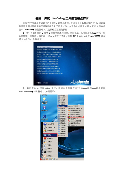
1、我们将制作好的u深度U盘启动盘连接电脑,重启电脑,在出现开机logo时按下启动快捷键,选择从U盘启动,进入u深度主菜单后选择【03】运行u深度win2003PE增强版(老机器),如图所示:
2、随后进入u深度03pe系统,在桌面上依次点击“开始——程序——磁盘管理——UltraDefrag碎片整理”,如图所示:
3、进入UltraDefrag碎片整理工具主界面,上方会显示电脑上各个盘的列表,很直观,此时我们点击选择需要进行碎片整理的磁盘,然后点击“整理”,如图所示:
4、工具开始工作,左下方会显示进度百分比,我们等待完成即可,如图所示:
5、完成后看到有碎片,点击“优化”进行处理,如图所示:
碎片整理的操作就到此为止了,需要整理碎片的用户可以按照本文的方法进行操作,我们在使用电脑过程中要经常注意维护电脑,让电脑一直出于健康状态。
希望这个方法可以帮助到有需要的人。
存储故障磁盘超强纠错技术简介
1. 概述背景近年来硬盘容量急剧增大,单块硬盘从过去几百G到现在主流的3TB、4TB,再到更高的6TB 硬盘,传统的RAID机制碰到了极大的挑战。
大容量硬盘再带来高性价比的同时,也使得硬盘数据的安全问题愈加明显,在这其中最突出的就是硬盘故障率过高。
经过大量实践考验的10年存储经验积累,我司将硬盘故障导致的故障时间减少80%,市场上磁盘故障率由3%降低到了0.4%,远低于业界水平。
这种质的飞跃,得益于我司的故障磁盘超强纠错技术,能够提供多种有效机制对磁盘和阵列进行容错处理,提高RAID可靠性:➢磁盘微代码处理➢磁盘错误修复/阵列巡检➢磁盘SMART检测及预拷贝➢磁盘两级坏道替换机制➢允许多块磁盘同时发生介质错误➢阵列超级块冗余设计2. 容错技术2.1磁盘微代码处理硬盘在读写过程中可能返回错误代码,所有的错误代码都以scsi sense code向RAID层返回,各种不同的错误代码均有其特定的含义,覆盖磁盘坏、磁盘介质错误、链路问题、磁盘abnormal 或是磁盘重分配扇区满等等。
RAID层将针对不同的错误代码,智能地采取不同的处理策略。
2.2磁盘错误修复/阵列巡检该技术主要适用于冗余RAID类型阵列。
磁盘读错误修复:当读RAID中磁盘数据的时候,其中一块磁盘出现读介质错误,并且读错误的条带为冗余条带。
根据RAID的算法特点,可以读出同一条带其他磁盘的数据,进行运算,得到该磁盘正确的数据。
将运算获得数据重新写到磁盘上,写成功之后,也意味着修复了该磁盘。
阵列巡检:系统周期性对冗余RAID进行数据一致性检测,对存在数据错误的硬盘坏道进行自动修复。
该机制的修复条件和修复措施基本同磁盘错误修复。
两者不同之处在于:磁盘错误修复是被动检测到磁盘有读错误上报及时进行处理,而阵列巡检则是主动监测阵列坏道状况,预先进行处理。
阵列巡检过程需要定义巡检周期。
巡检描周期是对所有需要扫描的RAID进行一次坏道巡检的时间间隔。
- 1、下载文档前请自行甄别文档内容的完整性,平台不提供额外的编辑、内容补充、找答案等附加服务。
- 2、"仅部分预览"的文档,不可在线预览部分如存在完整性等问题,可反馈申请退款(可完整预览的文档不适用该条件!)。
- 3、如文档侵犯您的权益,请联系客服反馈,我们会尽快为您处理(人工客服工作时间:9:00-18:30)。
S u p e r mi c r o 总 裁 兼 首 席 执 行 官
● A1 S A7 . 2 7 5 0 、 l x英 特 尔⑩ 凌
( 消息 来源: S u p e r Mi c r o C o mp u t e r , I n c )
( 上接 第 1 8 页)
● 一 一 体化 平 台: S i t e c o r e E x p e r i -
供实时支持 。
● 全球能力 : 对 于 在 世 界 各 地 开 展业 务 的品牌来说 , S i t e c o r e能 够 为 其 提 供 大 量 的 全 球 数 据 并 实 现 本 地 化 交
付。
( 消息 来源: S i t e c o r e )
e n c e Da t a b a s e与 S i t e c o r e E x p e r i e n c e
S u p e r m i c r o ( R ) 推出 1 U 3 2 ¨1 2 x 3 . 5 ¨ 硬 盘 存储 解 决 方案
标准机 架外 形和 免工具设计让您轻松部署和维修
加利福 尼业 州圣何 塞 2 0 1 4年 5月 2 8日 电 / . . 全 球 高性 能 、 高 效 率 服 务 器、 存 储 技 术 创 新 及 绿 色 计 算 领 域 的领
跑者 S u p e r Mi c r o C o mp u t e r , I n c . ( NA S ・
C h a r l e s L i a n g表 示 : “ 对 于 目前 需 要 在 最 小 功 耗 和 散 热 条 件 下 实现 快 速 数 据 访 问的分层存 储架构 来说 , S u p e r mi c r o 最新的 1 U 存 储 服 务 器 正 是 它 们 的 最 佳 解 决 方 案 。我 们 在 设 计 时 就 希 望 新 系 统 能够 节 省 能源 , 同时 尽 量 提 高 不 经 常 访 问数 据 的访 问 能 力 。 凭 借 我 们 的
紧凑型凌动 ( A t o m) C 2 0 0 0服 务器主板 和 至强 UP 配 置, 我 们 已经在 多种应用
中 实现 了性 能 、 容 量 和 节 能 的 完 美 平 衡, 同 时 保 有 一 个 高度 可 扩 展 、 具 有 成
本 效 益 的存 储解 决方 案 。 ”
紧 凑型、 低 功耗且基于 I n t e l ( I n t e 1 ) (  ̄ ) 凌
动 ( A t o m) C 2 7 5 0 的 冷 储 存 服 务 器 主 板, 通过该 l 丰板 降 低 转 速 或 关 闭 空 闲 驱 动 器及 管理 数 据 流 , 从 而 最 大 限 度 地 减
基 于 云 计 算 的 冷 储 存 和 驱 动 器 降
速
动 ( 8 核) 、 高达 6 4 GB、 1 2 x 3 . 5 英 寸 硬
4 0 0 W 电源
特尔⑩至强 ( X e o n )  ̄ E 3 — 1 2 0 0 v 3和
E 5 — 1 6 0 0 / 2 6 0 0 v 2处 理 器 的 多 种 配 置 。
完 整 的解 决 方 案 可 直 接 部 署 在 紧 凑 的
l u 3 2英 寸 机 架 内 , 支持高达 4 8 T B / 7 2 T B 3 . 5 英 寸 硬 盘 存 储 。2 个 1 G b E端 口或 1 0 G B a s e — T 、 S F P +端 口 带 来 了 灵 活的网络连接方案。此外, 该 系 统 采 用 拥 有 最 大 故 障 恢 复 能 力 的冗 余 4 0 0 W/
6 0 0 W 高 效 电源 。
● X9 S R H— T P F 、 l x英特 尔⑩ 至
强⑩ E 5 — 1 6 0 0 / 2 6 0 0 v 2系 列 ( 6 — 1 2 核) 、 高达 2 5 6 G B E C C L R / R DI M或6 4 GB E C C U DI MM 、 1 2 x 3 . 5 英寸硬盘 、 板 载
1 0 Gb E S F P + 、 冗余 6 0 0 W 电源
● 用 于分 析 的 大数 据 平 台或 数 据 湖( Da t a L a k e ) 、 向外 扩 展 , 云 环 境 内 的 对 象 存 储 平 台 ● 大 数 据 分 析 和 原 生 Ha d o o p 2 . 0实 时应 用
( S G- 5 0 1 8 A— AR1 2 L )
● X I O S L 7 、 l x英特 尔⑩ 至 强⑧
E 3 — 1 2 0 0 v 3 s e r i e s ( 4核 ) 、 高达 3 2 G B、 1 2 x 3 . 5 英 寸硬盘, 1 0 G b E附 加 卡 、 冗 余
盘、 1 0 G b E附 加 卡 、 冗余 4 0 0 W 电 源
少了功耗, 降低 了散热要求 。对于更多
数 据 密 集 型应 用 , 该 公 司 推 出了 搭 载 英
● A1 S A7 . 2 5 5 0 、 l x英特 尔⑩ 凌
动 ( 4核 ) 、 高达 6 4 G B、 1 2 x 3 . 5 英 寸 硬 盘、 1 G b E 、 冗余 4 0 0 W 电源 ● 线上 、 低层 、 横 向 扩 展 存 储
D AQ: S MC I 1 推 出全 新 的 紧 凑 型 具 有 成 本 效 益 的存 储 解 决 方 案 , 该 方 案配 备
了其 新 的 S S G. 5 0 1 8 A — A( R / S )1 2 L超 级
存 储服 务器 ( S u p e r S t o r a g e S e r v e r ) 。 这 种 专用存储 服务器搭 载 S u p e r mi c r o的
