JWG-1使用说明书
无线膜式燃气表说明书-钢壳

1前言本产品适用于城市管道燃气、天燃气和液化石油气的自动计量和收费控制。
该产品的使用提高了供气行业的现代管理水平,同时方便了用户的使用,解决了抄表难、入户难、监控难、收费难等诸多问题。
本产品执行标准GB/T6968‐2011膜式燃气表,采用公共频道的无线通信方式。
金卡高科技股份有限公司是国家级软件企业,浙江省高新技术企业,是集研发、生产、销售于一体的无线表专业厂家。
本产品符合GB3836.1-2010《爆炸性环境第1部分:设备通用要求》和GB3836.4-2010《爆炸性环境第4部分:由本质安全型“i”保护的设备》标准;防爆标志为ExibIIBT3Gb。
型式批准证书编号:2014F380-33JW-G1.6、2.5、4G2014F380-33JWML1.6、2.5、4FG企业宗旨是:人才为本,科技导航质量创牌,用户满意。
金卡高科技股份有限公司真诚感谢阁下对我们的支持,为确保正确安装及使用,请详阅本说明书。
2工作原理2.1产品组成部分:JW系列无线膜式燃气表JWML系列IC卡无线膜式燃气表膜式燃气基表√√智能控制模块√√电机阀√√IC卡模块√无线收发模块√√2.2工作原理:JW系列无线膜式燃气表、JWML系列IC无线膜式燃气表有四个气室,由两个皮膜分隔而成。
燃气流经时,在四个气室内产生不同的压强,使皮膜做往复运动,经过一系列的传动机构,再经传感系统,把机械运动转化为电信号送至智能控制模块。
实现计量、查询、提示和开关阀等各种功能。
3产品尺寸4技术指标参数名称单位 1.6型 2.5型4型公称流量m3/h 1.6 2.54最大流量m3/h 2.546最小流量m3/h0.0160.0250.04最大工作压力kPa15基本误差限%q min≤q<0.1q max时±30.1q max≤q≤q max时±1.5密封性kPa22.5kPa压力下3min内不泄漏最小读数dm30.2最大读数m399999使用温度℃‐25~55使用气体各类燃气、空气、无腐蚀性气体进出气管螺纹mm M30×2进出气管中心距mm130计量范围m30~99999.999m3计量精度级 1.5总压力损失Pa<250工作电压V DC4.8V–6.3V(4节碱性电池)静态电流uA≤20数据保存年>105产品使用环境和安装条件5.1环境温度:‐25℃~55℃5.2环境湿度:30%~85%RH5.3最大工作压力:15kPa5.4燃气表在运输途中不得倾倒、遭受严重碰撞和振动。
维金Lite方向控制阀门值,G1 8,G1 4和G3 8说明书

3
Strategic Rationale
• To penetrate the global in-line valve market
• $100m addressable market
• Highly competitive product to address the in-line valve market in all regions of the world
• Overview • Specification • Design features • Options & accessories • Viking Lite & Xtreme – product differences
• Price & product positioning • Launch date • Summary
Viking Lite
Directional Control Valves
G1/8, G1/4 & G3/8 Body Ported
08 November 2019
Viking Lite
Table of contents
• Strategic rationale • Product information
Accessories
• Manifold bar - Anodised aluminium • Pressure bar - Anodised aluminium
10
Viking Lite
Table of contents
• Strategic rationale • Product information
Acom JW-1 高级顶加载权重衡器用户手册说明书

Acom Corporation would like to thank you for purchasing our model JW-1 Advanced top loading balance. We are committed to creating high quality low maintenance products and supplying our customers with diligent customer service. This manual contains information on the proper assembly and use of the scale.
Disclaimer:
This company makes no representations or warranties, either expressed or implied, with respect to the contents hereof and specifically disclaims any warranties of merchantability or fitness for any particular purpose. Any software described in this manual is sold or licensed “as is”. Should the programs prove defective following their purchase, the buyer (and not this company, its distributors, or its dealers) assumes the entire cost of all necessary servicing, repair, and any incidental or consequential damages resulting from any defect in the software. Further, this company reserves the right to revise this publication and to make changes from time to time in the contents hereof without obligation to notify any person of such revision or changes.
JWK-1产品使用说明书
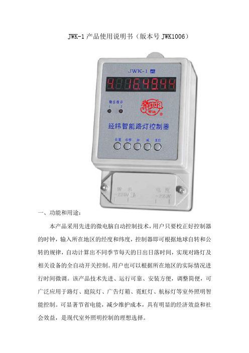
JWK-1产品使用说明书(版本号JWK1006)一、功能和用途:本产品采用先进的微电脑自动控制技术,用户只要校正好控制器的时钟,输入所在地区的经度和纬度,控制器即可根据地球自转和公转的规律,自动计算出不同季节每天的日出日落时间,实现对路灯及相关设备的全自动开关控制。
用户也可以根据所在地区的实际情况进行时间微调。
该产品技术先进、运行可靠、安装方便,调整简便,可广泛应用于路灯、庭院灯、广告灯箱、霓虹灯、航标灯等室外照明智能控制。
可显著节省电能,减少维护成本,具有明显的经济效益和社会效益,是现代室外照明控制的理想选择。
本控制器有两路输出,第一路为全夜灯,即天黑亮灯、天亮关灯;第二路用户可自己设定晚间关灯时间和早晨开灯时间,也可以设置成全夜灯。
用户可以让一部分路灯晚上长亮,另一部分路灯定时关闭,既满足了照明需要,又能最大限度的节省电能。
本产品可根据用户需要附加光控或雨控功能;如果是在-20度以下环境使用,可增加内部保温附件,保温附件在低于5度加温,高于10度停止加温。
请在购买时特别说明。
二、主要技术指标:1、使用范围:东经70~136°,北纬5~60°,全国各地均可使用。
2、时钟误差:±1秒/天。
3、一路输出:全夜灯,用户开关灯调整范围±99分。
二路输出:半夜灯/全夜灯,用户开灯调整范围±99分,关灯时间用户自定。
4、输出功率:220VAC/3A/10A.5、工作电压:220VAC/50/60Hz。
6、停电数据保护时间:四个月。
7、环境温度:-20~+60℃(低于-20度可增加内部保温附件)8、环境湿度:<95%9、外形尺寸:125×82×68mm10、重量: 365g三、使用说明:该产品投入使用前,用户务必进行时钟、经纬度的初次设定,请按以下步骤进行:1、了解面板及各部分功能用途:1)八位LED数码管,显示相关时间及数据。
2)五位按键,分别是:设置、右移、+1、-1、复位。
网络教学综合平台教师简明使用手册
安徽大学网络教学综合平台教师简明使用手册清华大学教育技术研究所2010 年02 月J lil 硼网络教学综合平台--教师用户简明使用手册图1-2平台登录首页(登录后点击“进入”按钮)教师首页”、课程教学” “精品课程”、和课程展示”第一部分登录系统第一步:登录网络教学综合平台如图所示:输入用户名和密码。
农卡胃"版盂It 強松WftJS ・Cl-dHf ・ 畫样軽軒哝期厦动■诜口貧哥林飙■母冉事,宙挣ii 诉诃推H ・T T rlR 平 iJ^TUtWlf*l»JWHTTR[ it 爭也工¥晴电于H 学禺強;t 序厦 讣!TF :科学与技*半隱RC¥ttHWSl£计.古羸霞鞏攻穆斗评罚童录議鲂乞+力建慳了■天的辛Ml 番* 工鼻址冏jsstieM ■纯.曲!(供丁览廿的曰主壬动功配.ffjtss Tilrar-#^if.H$L9KYT^畀利诗计琴診*■此"*ff1Wfirlift,忸是整出一 H 主"-ifrff灯说' 事丘比書怕理工制MF. 5F±*P±IS5iBft1T. *宦牯界辛主坯JSJtfJ 年TlH 力fte 可布■怔邛伺内L :■力杵握弋價的古式詮・样叮刊中. dn-KKliWBIhhdt*7T ■ ■■計 ・《 *1* 册,■ Ml HWf 血 E U W* 啬■Dp^^^on4 ■吕 urn*图1-1 访问网络教学综合平台登录系统后,继续点击“进入”按钮,进入平台,如下图所示页面。
»JE#■穴!E 套整甲J :査竹零决特辛,區丹岷讨■釈$摩垃*支片1•章创留.frtfjli.且三睾k,肉柞-马恵1;壬:t 厳出鸟再工mMdQ (DH1XB : 1 壬*则蓝:即鼻罔页面上方列出了四个导航栏,分别是:・欣注像用曲霰#峰齿3吃卜 «j |ig./ria n.m.■玄 1 Iff 昌伦即 | ltrF€# | E7N4JF . utt^ *1肯#叫r*K »SuH*4U«BtTf.5 st.-fS. £兀片主厅理弓貳十;事亡灯箱7.勺評岬If I 士丁響丁旳不贰岳讶ZAftFlfSFW 井ltftTlEfl-P*Pt3ttW tt^fiST«nfft2Hr'京E?聘用舸圧"¥蔺告:風络教学Mt ]号、冃「日互功辺Anciuici 円二勻s4个、整凋J MTiZ^ij&应申習询图1-4修改密码页面第二部分通用网络教学平台第一步:进入课程教学空间A *JT 妙 ffiti -fl 1H4撫学荷圧俵G E 掙亡祥4严莘甘芹 △曲咅ti 瞬住 CS Fl 上3;坛 'iftri*7FAwfflafl i 杠曲B 甲谓"忑星暉B 凸府珂百和宫丁1&=一读宦炜莒誓也也晦qgi 査H£律丼设弹甚盘看■逋亦|短正莊航覆I 门度轻耳亢鼻主丈两港皂济竿仃 迴J 輕[](« 删tftL 聊户)1尽0 「「『 敕攪妁课稈辱*2二岂配T 泊怙;齐土_|色<童!_(iitfr-rr ;TI = I图1-3进入系统之后的教师首页第二步:修改密码进入平台之后,您可以修改自己的密码。
JWG-1型防水材料特点
涂料招聘网中国涂料行业权威招聘网站!!!JWG-1型防水材料特点JWG-1防水组合是由JWG-1型渗透式防水剂(专利号:01106169.3)和JWG-M型防水膏(专利号:ZL01106168.5)组成。
JWG-1防水组合解决家庭浴室、卫生间、窗口、露台等漏水问题搭配设计。
产品可以用于军用设施和文物保护。
在浴室、卫生间、外墙、屋顶、露台、水池等瓷砖及水泥表面使用,能够真正实现了不刨不砸解决漏水问题。
任何人都可以独立轻松完成防水维修。
产品一经使用即可和建筑体融为一体,形成优质完美的防水层。
室外使用耐久性长达10年以上,而针对室内卫生间使用,防水效果终身有效。
现在全国已有十几万例漏水的卫生间、厨房、泳池浴池等验证了这套产品的神奇!防水剂简介:JWG—1防水剂(专利号:01106169.3)是一种无毒、无味、不燃、无污染、环保型高分子聚合物防水材料。
具有优良的渗透性、防水抗渗透性、耐腐蚀性、耐磨性及耐候性,施工简便快捷、省人省时省力、造价低、防水效果好。
不破坏原有装饰做防水维修。
防水膏简介:JWG-M型防水膏是由JWG-M型防水(专利号:ZL01106168.5)固化剂等材料复合调配制成,由白色膏的状防水膏和调节剂组成的无毒、不燃、不发挥的复合型绿色防水材料。
适用于屋面、墙面、地下室、卫生间、蓄水池、泳池浴池、外墙体渗漏、窗口渗漏等防水工程。
"刚柔互补、刚柔一体、凝固时间可调、硬度可调、带水施工"是久固JWG—M型防水膏区别于其它同类防水材料的重要标志。
K13防水材料特点针对现代家庭装修和工程装修对防水材料的环保、防霉、防水等性能要求而专门开发的新型双组分高性能环保型防水材料。
● 可以在潮湿基面上直接施工。
● 具有超强粘结力和极佳背面抗渗性。
● 涂层致密,凝结期短。
● 与混凝土、砖石等基材粘结力强。
● 抗压强度高,可用于迎水面防水面防水。
● 体积稳定,防止龟裂,涂层抗渗性强,可长期泡水。
电子天平电子秤校准作业指导书pdf
电⼦天平电⼦秤校准作业指导书pdf1.0 ⽬的:保证计量仪器的有效使⽤,确保产品实现过程的质量2.0 适⽤范围;本公司以下的电⼦天平及电⼦秤:2.1 JW-300 电⼦计重秤(北京宇权,300g/0.001g)2.2 T-500 电⼦天平(常熟双杰,500g/0.01g)2.3 JY-1001 电⼦天平(上海民桥,1000g/0.1g)2.4 JZC-3S 电⼦秤(福州科迪,3000g/0.5g)3.0 校准依据:3.1 CSB/QP-13《检测设备管理程序》3.2 JJG98-1990《⾮⾃动天平试⾏检定规程》3.3 JJF105《测量不确定度评定与表⽰》4.0 职责:4.1 品管部计量管理⼈员负责计量仪器的校准⼯作。
4.2 相关使⽤部门配合计量管理⼈员进⾏校准⼯作。
5.0 校准⽅法:5.1 校准项⽬:5.2 校准条件与设备:5.2.1 室内温度:18-28℃,湿度≤75%RH5.2.2 所⽤设备:已检定5~1000g ⼀组砝码(9 个).5.3 校准过程:5.3.1 外观:a. 天平上应有型号,名称,出⼚⼚名,最⼤秤量,分度值,准确度级别(⽤⼀个椭圆和椭圆⾥⾯的罗马数字,外加数字外脚标表⽰).b. 天平表⾯镀层应⾊泽均匀,不得有明显的划痕和擦伤.5.3.2 ⾃动校准:5.3.2.1 JW-300 电⼦计重秤(北京宇权,300g/0.001g)a. 按住功能转换键,同时按开/置零键开机,待显⽰” CAL-.1”时放⼿;b. 再按功能转换键,显⽰” YES-CAL.0-LOAD ”→” XXX.XX或”” XXX.XX”两种重量循环显⽰;c. 加⼊已检定的200g 砝码;d. 稳定后显⽰”CAL.2”并发出”嘟”声,按百分⽐/重量键退出.e. 校准结束.5.3.2.2 T-500 电⼦天平(常熟双杰,500g/0.01g) :a. 按”校正” (CAL键) ,显⽰窗显⽰”C-XXX- “进⼊⾃动校正状态(XXX 为校准砝码的重量).b. 将砝码放于秤台上,待稳定后天平显⽰砝码重量值.c. 显⽰值与标准砝码值不符合时(e≠ d,)重新进⾏校准.d. 校准完毕.5.3.2.3: JY-1001 电⼦天平(上海民桥,1000g/0.1g)a. 按⼀下键,天平显⽰全”0”再,长按10 秒打开,显⽰窗出现”CAL”符号;.b. 松开键,显⽰窗出现C-XXX(校正砝码值),将相应的校正砝码放于天平秤上;.c. 过⼗⼏秒后,天平⾃动校正完成.d. 若不准确,可按上法再进⾏⼀次校正.5.3.2.4 JZC-3S 电⼦秤(福州科迪,3000g/0.5g)a. 在秤盘上不加载任何物体,按住”清零”键开机.b. 此时显⽰”CAL”字样,待显⽰稳定后,按”清零”键⼀次,显⽰” 0KG”字样.c. 按”单位”键选择相适宜的砝码重量值(1000g),放上校准砝码,按”清零”键认,即刻显⽰校准砝码的重量值.d. 校准操作最好在开机预热1 ⼩时后进⾏,当误差超过±10%时,校准⽆效,重新校正.: 量⽖两外测量⾯接触后,游标上的”零”刻线和”尾”刻线与尺⾝相应刻线应相互重合.5.3.3 载荷点最⼤允许误差a. 载荷点确定:使⽤⾃动校准,各电⼦天平型号不同,选择的载荷点也不同:JW-300 电⼦计重秤(北京宇权,300g/0.001g): 0, 10g, 20g, 50g, 100 g, 100g共 6个点. T-500 电⼦天平(常熟双杰,500g/0.01g): 0, 20g, 50g, 100 g, 100g, 200g共6 个点. JY-1001 电⼦天平(上海民桥,1000g/0.1g): 0, 50g, 100g, 100 g, 200g, 500g共 6 个点. JZC-3S 电⼦秤(福州科迪,3000g/0.5g): 0.100g,200g,500g,500g,1000g共 6 个点.b. ⽅法: 从零载开始,逐渐加到天平的最⼤加法配衡(能达到天平最⼤载荷最好),再逐渐地卸下载荷,直⾄零载荷为⽌,记录相关的数据...c. 误差计算: 各载点的⽰值误差: E=I+1/2e-L.式中;E - 载点的⽰值误差I ---- 天平加载或卸载时的显⽰值.e --- 天平的分度值L --- 载荷量,即加⼊砝码的总重量.d. 测定结果判定: ⽐较各载点的⽰值值误差 E 是否超过该天平相应载荷时的最⼤允许误差绝对值MPE.(参阅电⼦天平的使⽤说明书及标⽰).e. 举例说明:以JZC-3S 电⼦秤为例5.3.4 ⽰值重复性:a. 载荷点确定:JW-300 电⼦计重秤(北京宇权,300g/0.001g): 载荷点200 g.T-500 电⼦天平(常熟双杰,500g/0.01g): 载荷点200g.JY-1001 电⼦天平(上海民桥,1000g/0.1g): 载荷点500gJZC-3S 电⼦秤(福州科迪,3000g/0.5g): 载荷点1000g.b. ⽅法: 在电⼦天平中央,加⼊载荷点要求的砝码重量,记录天平显⽰值和零位值,重复进⾏ 3 次, 每次载荷应返零⼀次..c. 结果计算与判定:测定结果的最⼤值与最⼩值之差为⽰值重复误差.⽰值重复性误差应不⼤于最⼤允许误差绝对值MPE.(参阅电⼦天平的使⽤说明书及标⽰).e. 举例说明:以JZC-3S 电⼦秤为例5.3.5 偏载(四⾓误差):XXXXXXXX有限公司标题:计量仪器校准作业指导书电⼦天平/电⼦秤编号:CSB/WI-QC-05-03版次:A修订号:0第4页共5 页发布⽇期实施⽇期JW-300 电⼦计重秤(北京宇权,300g/0.001g): 载荷点200 g.T-500 电⼦天平(常熟双杰,500g/0.01g): 载荷点200g.JY-1001 电⼦天平(上海民桥,1000g/0.1g): 载荷点500gJZC-3S 电⼦秤(福州科迪,3000g/0.5g): 载荷点1000g. b.⽅法:在秤盘上,按上图的1,2,3,4,5 位置依次放⼊规定砝码,记录天平显⽰值...c. 结果计算与判定:测试结果中的最⼤值与最⼩值之差即为偏载误差(四⾓误差). 偏载误差应不⼤于最⼤允许误差绝对值MPE.(参阅电⼦天平的使⽤说明书及标⽰).e. 举例说明:以JZC-3S 电⼦秤为例序号位置添加载荷砝码真实值载荷显⽰值偏载误差最⼤允许误差MPE结果判定11100010001000.00.3±0.5合格22100010001000.23310001000999.944100010001000.055100010001000.15.65.6.1 A 类不确定度(测量分散性):U A=式中: Xi --- 各测试点测试温度,℃X0 -- 各测试点测试温度的平均匀埴, ℃n --- 测试的次数5.6.2 B 类不确定度(砝码不确定度):U B(砝码检定时给出,详见检定证书)2 25.6.3 合成不确定度U C= U A+ U B5.6.4 扩展不确定度:U=k U C(k=2)5.7 校准周期:第1,2 项每⽉1 次,其它为6 个⽉校准⼀次5.6 量值溯源图6.0 记录及表格6.1《计量仪器校准报告》编制:审核:批准:⽇期:⽇期:⽇期:编号:CSB/WI-QC-05-03版次: A 第5页发布⽇期修订号:0 共5 页实施⽇期。
德力西电气 S(D)JW-G智能无触点交流稳压器产品样本2022年第1版 产品说明书

DJW-G-10kVA SJW-G30kVA SJW-G-200kVA交流稳压器智能无触点D (S )JW-G工业级■产品特征本系列工业级智能无触点交流稳压器分为单相DJW-G、三相SJW-G两种,主要由隔离变压器、SCR模块、CPU核心控制、实现了全无触点控制采用最新DSP运算计量芯片控制、快速交流采样、有效值校正、过零切换和快速补偿稳压技术,将智能仪表、快速稳压、故障诊断结合在一起,度高、响应速度快、无机械磨损、安全、高效。
广泛应用于工业、交通、邮电、通信、国防、铁路、科研等领域的大型机电设备、金属加工设备、生产流水线、电梯、医疗器械、刺绣轻纺设备、空调、广播电视、家用电器及大楼照明等需要稳定电压的用电,核心控制是SCR开关技术和变压器技术的完美结合,■ 选型指南额定功率 kVA JW-G□产品型号10:1020:2050:50100:100....1600:1600智能无触点交流稳压器D:单相S:三相■ 产品特点◇ CUP 智能控制、数字电路、稳定可靠;◇ 智能液晶显示:智能仪表实时显示电压、电流有效值,清晰、准确、人性化人机操作界面。
◇ 三相分调,输出电压不平衡度小于1%,每相输出电压的精度不变,无触点、无磨损、免维护。
◇ 高速反应:稳压响应时间小于40毫秒,对电脑自动化、设备及仪器,不产生电压变化影响。
◇ 高精度:产品输出电压精度±1%~±5%可设定, 最高稳压精度为±1%。
◇ 通讯接口:机内配置RS -232通讯接口(选购)。
◇ 抗干扰、净化能力强、使输出电力完全纯净。
◇ 适用范围广:稳压范围宽,可满足电源电网质量差、电压波动范围大的场所及设备使用。
◇ 保护功能齐全:设有过载、过压、欠压、短路等故障显示和保护功能,确保稳压器及负载安全运行。
◇ 预置功能强:过流保护限值可以任意设定。
◇ 适应性强:对电网和负载的适应性强,可在各种恶劣的电网和复杂的负载情况下,可靠地连续稳定工作。
G-1滚动灯箱控制器说明书
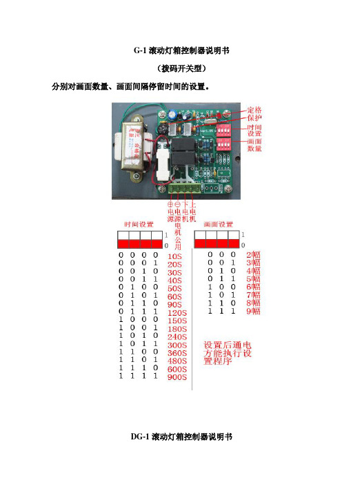
G-1滚动灯箱控制器说明书(拨码开关型)分别对画面数量、画面间隔停留时间的设置。
DG-1滚动灯箱控制器说明书(数显型)主要功能说明本控制器采用双传感器,画面幅数,和停留时间自行设置,时间显示具有双电路的时间控制功能。
依次按“←”键分别对画面数量、画面间隔停留时间、调整钟表时间、灯光开启时间、灯光关闭时间、设备(电机滚动系统)开始时间、设备(电机滚动系统)关闭时间的设置。
1、画面数量设定按“←”键,屏幕出现例:02”闪动,说明当前的画面数量为2幅,按“↑”“↓”键来设置画面的数量。
(按“确认”键保存设置,按“取消”键重新设置)画面数量最多可设置为9幅。
2、画面间隔停留时间设定依次按“←0.4”闪动,说明此时的间隔停留时间为“0.4”分钟,既为“24”秒钟,按“↑”“↓”键设置间隔停留时间。
间隔停留时间范围为0.1—9.9分钟可调(按“确认”键保存设置。
按“取消”键重新进行设置)。
3、调整钟表时间依次按“←”键,此时“00”闪动,说明此时进行分钟校准的操作步骤:按“↑”“↓”键调整分钟时间,再按“→”键切换为小时的设置,此时“18”闪动,再按下“↑”“↓”键调整时间的范围(按“确认”键保存设置。
按“取消”键重新进行设置)。
4、灯光定时设置①依次按“←”键,进行灯光开启时间设置,屏幕出现例:,此时“:00”闪动,按“↑”“↓”键进行分钟调整,再按下“→”键切换为小时的设置,屏幕上“18”闪动,按“↑”“↓”键对灯光开启时间进行范围调整(按“确认”键保存设置。
按“取消”键重新进行设置)。
②依次按“←”键,进入灯光关闭时间设置,屏幕出现例:,此时“:00”闪动,按↑”“↓”键进行分钟调整,再按下“→”键,进入“小时”操作步骤,此时“18”闪动,按“↑”“↓”键调整小时范围(按“确认”键保存设置。
按“取消”键重新进行设置)。
5、广告机设备(电机滚动系统)工作时间设置①依次按“←”键,进入设备开始时间设置,屏幕出现例:时“:00”闪动,按“↑”“↓”键进行“分钟”调整,再按“→”键,进入“小时”操作,此时“18:”闪动,再按“↑”“↓”键调整小时范围(按“确认”键保存设置。
XLJ-G1系列真空角阀商品说明书
Doc. no.XL-OMU0002-AVacuum Angle Valve(Vacuum Pilot)XLJ- -*G1 SeriesThank you for purchasing this SMC product.Be sure to read this Operation Manual carefully and understand its contents before operating this product to ensure the safety of the operator and this product.Please refer to the drawing and other informative documents for the construction and specifications of this product.Further, ensure your operating environment satisfies the requirements specified for the product.Keep this Operation Manual available whenever necessary.2540Safety Instructions - - - - - - - - - - - - - - - - - - - - - - - - - - - - 2 1. Product Specific Precautions 1 - - - - - - - - - - - - - - - - - - - - - - - - - - - - 4(Precautions on Design, Selection, Mounting, Piping, Wiring, Maintenance) 2. Product Specific Precautions 2 - - - - - - - - - - - - - - - - - - - - - - - - - - - - 5(Maintenance parts)3. Specifications - - - - - - - - - - - - - - - - - - - - - - - - - - - - 64 Construction and Outer dimensions - - - - - - - - - - - - -- - - -- - - - - - - - - - - - 75. Period and scope of warranty - - - - - - - - - - - - - - - - - - - - - - - - - - - - 86. Parts replacement procedure - - - - - - - - - - - - - - - - - - - - - - - - - - - - 9Safety InstructionsThese safety instructions are intended to prevent hazardous situations and/or equipment damage. These instructions indicate the level of potential hazard with the labels of “Caution,” “Warning” or “Danger.”They are all important notes for safety and must be followed in addition to International Standards (ISO/IEC)*1), and other safety regulations.*1) ISO 4414: Pneumatic fluid power -- General rules relating to systems ISO 4413: Hydraulic fluid power -- General rules relating to systemsIEC 60204-1: Safety of machinery -- Electrical equipment of machines (Part 1: General requirements) ISO 10218-1992: Manipulating industrial robots -- SafetyCaution Caution indicates a hazard with a low level of risk which, if not avoided, could resultin minor or moderate injury. Warning Warning indicates a hazard with a medium level of risk which, if not avoided, could result in death or serious injury.DangerDanger indicates a hazard with a high level of risk which, if not avoided, will resultin death or serious injury .Warning 1. The compatibility of the product is the responsibility of the person who designs theequipment or decides its specifications.Since the product specified here is used under various operating conditions, its compatibility with specific equipment must be decided by the person who designs the equipment or decides its specifications based on necessary analysis and test results.The expected performance and safety assurance of the equipment will be the responsibility of the person who has determined its compatibility with the product.This person should also continuously review all specifications of the product referring to its latest catalog information, with a view to giving due consideration to any possibility of equipment failure when configuring the equipment.2. Only personnel with appropriate training should operate machinery and equipment.The product specified here may become unsafe if handled incorrectly.The assembly, operation and maintenance of machines or equipment including our products must be performed by an operator who is appropriately trained and experienced.3. Do not service or attempt to remove product and machinery/equipment until safety is confirmed.1.The inspection and maintenance of machinery/equipment should only be performed after measures to prevent falling or runaway of the driven objects have been confirmed.2.When the product is to be removed, confirm that the safety measures as mentioned above are implemented and the power from any appropriate source is cut, and read and understand the specific product precautions of all relevant products carefully.3.Before machinery/equipment is restarted, take measures to prevent unexpected operation and malfunction.4. Contact SMC beforehand and take special consideration of safety measures if the product is to be used in any of the following conditions.1. Conditions and environments outside of the given specifications, or use outdoors or in a place exposed to direct sunlight.2. Installation on equipment in conjunction with atomic energy, railways, air navigation, space, shipping, vehicles, military, medical treatment, combustion and recreation, or equipment in contact with food and beverages, emergency stop circuits, clutch and brake circuits in press applications, safety equipment or other applications unsuitable for the standard specifications described in the product catalog.3. An application which could have negative effects on people, property, or animals requiring special safety analysis.4. Use in an interlock circuit, which requires the provision of double interlock for possible failure by using a mechanical protective function, and periodical checks to confirm proper operation.Safety InstructionsCaution1. The product is provided for use in manufacturing industries.The product herein described is basically provided for peaceful use in manufacturing industries.If considering using the product in other industries, consult SMC beforehand and exchange specifications or a contract if necessary.If anything is unclear, contact your nearest sales branch.Limited warranty and Disclaimer/Compliance RequirementsThe product used is subject to the following “Limited warranty and Disclaimer” and “Compliance Requirements”.Read and accept them before using the product.Limited warranty and Disclaimer1. The warranty period of the product is 1 year in service or 1.5 years after the product is delivered,whichever is first.*2)Also, the product may have specified durability, running distance or replacement parts. Please consult your nearest sales branch.2. For any failure or damage reported within the warranty period which is clearly our responsibility, a replacement product or necessary parts will be provided.This limited warranty applies only to our product independently, and not to any other damage incurred due to the failure of the product.3. Prior to using SMC products, please read and understand the warranty terms and disclaimers noted in the specified catalog for the particular products.*2) Vacuum pads are excluded from this 1 year warranty.A vacuum pad is a consumable part, so it is warranted for a year after it is delivered.Also, even within the warranty period, the wear of a product due to the use of the vacuum pad orfailure due to the deterioration of rubber material are not covered by the limited warranty.Compliance Requirements1. The use of SMC products with production equipment for the manufacture of weapons of mass destruction (WMD) or any other weapon is strictly prohibited.2. The exports of SMC products or technology from one country to another are govemed by the relevant security laws and regulation of the countries involved in the transaction. Prior to the shipment of a SMC product to another country, assure that all local rules goveming that export are known and followed.Common Precautions 1Be sure to read before handling.DesignWarning●All models1. The material of the body and the bonnet is A6063, the other materials for vacuum is SUS304, brass, equivalent material to SUS405,and PPS, and the seal material is FKM. In addition, the seal material sliding part for vacuum is applied vacuum grease (Y-VAC2). Use fluids those are compatible with using materials after confirming.2. Fluctuation of each voltage should be +/- 10% or less.Selection●All models1. Keep within the specified range of the pilot pressure.2. Fluid containing foreign matters and oil will cause malfunction and sealing failure. Remove such things from the fluid.Mounting● All models1. In high humidity environments, keep the valve packed until the time of installation.2. Perform piping so that excessive force is not applied to the flange sections. When there is vibration from heavy objects or attachments, etc., fix piping so that vibration will not apply torque directly to the flange section. Piping and wiring1. Before mounting, clean the surface of the flange seal and the O-ring with ethanol, etc.2. There is an indentation of 0.1 to 0.2mm in order to protect the flange seal surface, and it should be handled so that the seal surface is not damaged in any way.3. This product has piping directionality. Check the vacuum pump side and the chamber side shown on the construction drawing.4. A wire for wiring should be 0.5 to 1.25mm 2 or more as reference.5. In addition, the wire shall not be applied excessive force.6.The power supply shall be operated together with the power supply for a vacuum pump.If the fluid or reaction product (deposit) may cause the valve to become unsafe, the valve should be disassembled, cleaned and re-assembled by an operator who has sufficient knowledge andexperience (e.g. a specialist).CautionCautionWarningCaution1. Replace the bonnet assembly when the valve is approaching the end of its service life.*For the endurance cycles, refer to Section 5 (page 8).2. If damage is suspected prior to the end of the service life, perform early maintenance.3. SMC specified parts should be used for service. Refer to the Construction / Maintenanceparts table.4. When removing the valve seal and external seal, take care not to damage the sealingsurfaces. When installing the valve seal and external seal, be sure that the O-ring is not twisted.Common Precautions 2 Be sure to read before handling Maintenance PartsSMC specified parts should be used for service.Refer to the construction drawing.1.Replace the bonnet assembly when changing the sealant material. Due to the differentmaterials used, changing only the seal may prove inadequate.Bonnet assemblyDescriptionConstruction no.Valve size25 40Bonnet assembly 1 XLJ25-30-*G1 XLJ40-30-*G1 External seal/ valve sealDescriptionConstruction no.Valve size25 40External seal 3 AS568-030V AS568-035VValve seal 2 B2401-V24V B2401-P42VNote 1) Refer to the Construction of for the construction numbers.Note 2) A voltage symbol (same as How to Order) is entered into the mark *CautionOpen valve) When the solenoid valve is energized (simultaneously with the vacuum pump), theatmospheric vent port is closed, and the channel of the bonnet and the top of the piston are opened. If the pressure at the vacuum pump side decreases, the pressure at the top of the piston also decreases via the channels of the shaft and the body. The pressure difference generated at that time makes the piston move upward. If the pressure decreases more, the channel of the shaft is closed, but the pressure at the top of the piston decreases much more via the channel of the bonnet, and it opens the valve.Close valve) When energizing to the solenoid valve is stopped (simultaneously with the vacuum pump),the channel of the bonnet is closed, and the atmospheric vent port and the top of the piston are opened. As the top of the piston gets atmospheric pressure via the atmospheric vent port, the valve is closed as the piston moves downward with the built-in spring. When the piston moves downward further, the channel of the shaft is opened, and it leads atmosphere to the vacuum pump side. Note) Valve response depends on the pump capability. Please check and use this valve.ModelXLJ-25-*G1XLJ-40-*G1Flange (valve) size 2540Actuating type Normally closed (vacuum pilot)FluidEvacuation with inert gasOperating temperature oC 5~40 Direction of exhaust Fixed Note 1Operating pressure Pa (abs) Atmospheric pressure to 1×10⁻²Conductance l/s Note 2 1245Operating power voltage 100VAC, 200VAC,110VAC,220VAC,230VAC,240VAC,24VDC,12VDCElectrical entry GrommetLeakagePa ・m 3/sInternal 1.3 x 10⁻⁸at ambient temperature, excluding gas penetrationExternal1.3 x 10-6at ambient temperature, excluding gas penetrationType of flangeKF(NW)Main materialBody and bonnet: aluminum alloy, Main parts: SUS304 and FKM Solenoid valve: brass, SUS304, equivalent to SUS405, PPS, and FKMSurface treatment for bodyOutside: hard anodized Inside: basis materialVacuum greaseFluorine type grease: Y-VAC2Weight kg0.951.5ON operation(simultaneously with pump) Note 3 Valve opens by vacuum pressure of pump side.. OFF operation(simultaneously with pump)Pump side opens to atmosphere after closing the valve.Note 1 See “Operation Description” and “Construction Drawing”.Note 2 The conductance is “molecular flow” measured with an elbow pipe which has the samedimension with each flange.Chamber sideOFF OFF ON Vacuum pump side4.A B DEACDimensions [mm]The guaranteed period covers the period which finishes the earliest among 0.5 million operating cycles [with our durability test conditions], 18 months after shipping from us, and 12 months after starting the use of the product at your place or your customer’s place.Note: The product durability is varied depending on the operating conditions (such as a use with large flow rate).If the specification is not kept, or any non-conformance derived from mounting or replace of a device, an assembly, or an O-ring at your place occurs, the guarantee cannot be applied.If any failure occurs due to our fault during the guaranteed period, we will guarantee the non-conformance by delivering a substitute in the worst case. However, responsibility of any damage which is led by the product failure is not taken by us.Result of durability test(with the circuit shown on the right) Internal/ external leakage and operation were checked by opening and closing a valve at room temperature.It was confirmed that this product Satisfied the specification up to0.5 million cycles.6-1. PrecautionsBe sure to follow [1. Precautions 1] when disassembling the product for maintenance. Along with the precautions above, comply with the following precautions too.Warning•If it is expected that product materials may get stuck to the product, ensure safety isassured before handling. It is recommended to wear gloves and a mask.•Pay attention to the handling of components according to the procedure in the next itemonwards. Do not apply excessive force or impact. This will not only damage the productbut also decrease its performance and life expectancy.•It is not possible to disassemble the bonnet assembly of this product. If the componentsand assembly are damaged, or damage is expected, exchange the bonnet assemblyitself.•Do not disassemble the parts that are not explained in this operation manual. Theperformance and life may decrease. Also, it may cause danger.Step 1 Step 2 Step 4 Step 5 Step 6 Apply ethanol to a clea (such as BENCOT) to wipe off dust on O-ring sur face, and place the O-ring on the Loosen the bolts gradually in numerical order (alternately) with bonnet assembly held.Apply ethanol to cloth (such as BENCOT) wi pe off dust on surface and the e seal.A (gas release)Remove the e xte rnal seal from the bod y. (Mind damage the bod y mounting surface.)ppl y et han ol t o a c l ea n c uc h as B E NCOT) t o wi pe offt on t h e e xt e rn al s eal s urf and t he b od y m ount i ng s urf hen, m ount t h e e xt er nal s eal.Loosen the bolts gradually innumerical order (alternately) withbonnet assembly held.Step 4 Step 5A 40 size added WU1st Printing :UX 4-14-1, Sotokanda, Chiyoda-ku, Tokyo 101-0021 JAPANTel: + 81 3 5207 8249 Fax: +81 3 5298 5362URL Note: Specifications are subject to change without prior notice and any obligation on the part of the manufacturer.© 2009 SMC Corporation All Rights Reserved。
JWS开关说明书
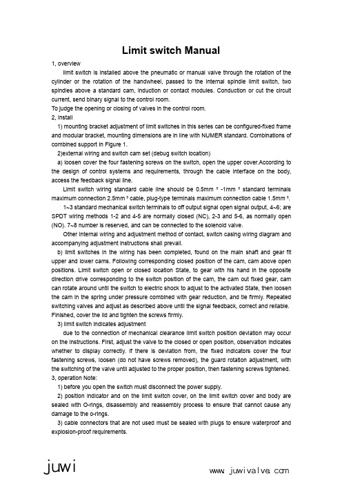
Limit switch Manual1,overviewlimit switch is installed above the pneumatic or manual valve through the rotation of the cylinder or the rotation of the handwheel,passed to the internal spindle limit switch,two spindles above a standard cam,induction or contact modules.Conduction or cut the circuit current,send binary signal to the control room.To judge the opening or closing of valves in the control room.2,install1)mounting bracket adjustment of limit switches in this series can be configured-fixed frameand modular bracket,mounting dimensions are in line with NUMER binations of combined support in Figure1.2)external wiring and switch cam set(debug switch location)a)loosen cover the four fastening screws on the switch,open the upper cover.According tothe design of control systems and requirements,through the cable interface on the body, access the feedback signal line.Limit switch wiring standard cable line should be0.5mm²-1mm²standard terminals maximum connection2.5mm²cable,plug-type terminals maximum connection cable1.5mm².1~3standard mechanical switch terminals to off output signal open signal output,4~6;are SPDT wiring methods1-2and4-5are normally closed(NC),2-3and5-6,as normally open (NO).7~8number is reserved,and can be connected to the solenoid valve.Other internal wiring and adjustment method of contact,switch casing wiring diagram and accompanying adjustment instructions shall prevail.b)limit switches in the wiring has been completed,found on the main shaft and gear fitupper and lower cams.Following corresponding closed position of the cam,cam above open positions.Limit switch open or closed location State,to gear with his hand in the opposite direction drive corresponding to the switch position of the cam,the cam out fixed gear,cam can rotate around until the switch to electric shock to adjust to the activated State,then loosen the cam in the spring under pressure combined with gear reduction,and tie firmly.Repeated switching valves and adjust as described above until the signal feedback,correct and reliable.Finished,cover the lid and tighten the screws firmly.3)limit switch indicates adjustmentdue to the connection of mechanical clearance limit switch position deviation may occur on the instructions.First,adjust the valve to the closed or open position,observation indicates whether to display correctly.If there is deviation from,the fixed indicators cover the four fastening screws,loosen(do not have screws removed),the guard rotation adjustment,with the switching of the valve until adjusted to the proper position,then fastening screws tightened.3,operation Note:1)before you open the switch must disconnect the power supply.2)position indicator and on the limit switch cover,on the limit switch cover and body aresealed with O-rings,disassembly and reassembly process to ensure that cannot cause any damage to the o-rings.3)cable connectors that are not used must be sealed with plugs to ensure waterproof andexplosion-proof requirements.juwiwww.juwivalve.com限位开关说明书1、概述限位开关是安装在气动阀门或手动阀门上面,通过气缸的转动或手轮的转动,传递给限位开关内部主轴,主轴上面有标准的两个凸轮,感应或接触模块。
JWY-1微机多功能油耗仪说明书

JWY-1 微机多功能油耗仪使用说明书Operating Manual尊敬的用户首先感谢您选用我公司的JWY-1 微机多功能油耗仪!在使用前请您仔细阅读本使用说明书,做好各项准备工作及记录,然后进行操作测试。
淄博双硕电子有限公司拥有本使用说明书的版权和解释权,并保留随时修改本说明书的权力。
在您使用我们产品的过程中,若对我们的产品有什么疑问或建议,请向技术服务部垂询。
本套设备自购买之日起保修壹年(人为性损坏、用户自行拆机不在保修范围之内),自购买之日起壹年内免费升级(软件),壹年后优惠升级。
用户在未付清全部款项之前,淄博双硕电子有限公司保留收回JWY-1 微机多功能油耗仪全部或部分的权力,以作相应的抵偿。
用户自购买之日起两个月内需将用户保修卡寄回:淄博双硕电子有限公司地址:淄博市张店区柳泉路286号邮编:255036安全注意事项为防止人员受伤、触电或引起火灾、仪器故障等,请您务必遵守下述注意事项:有关电源及充电安全的注意事项. 请使用220V 50Hz交流电源供给专配交流适配器对仪器进行充电。
. 初次使用或长久存放要有2至3次的充放电使用后内置电池才能达到正常的活性;仪器长时间不用时至少要二个月充电10~14小时一次,以保持内置电池活性,存放环境要阴凉、干燥、无腐蚀、灰尘。
. 一经发现交流适配器破损请立即更换,否则,有可能引起触电或火灾。
. 交流适配器插头插入插座时应保持良好接触,否则可能引起触电或火灾。
. 在拔插交流适配器插头时,务必用手拔插头而不能拉充电线。
否则会拉断充电线,引起故障。
安装注意事项请不要把本仪器放置或存放在以下位置,以免引起故障或不慎摔坏:. 不平稳的桌面或台面上。
. 日光直接照射的地方。
. 暖气设备附近。
. 温度剧烈变化的地方(避免结霜)。
. 温度过高或过低的地方。
. 湿度过高的地方。
. 灰尘过多的地方。
. 易受冲撞或震动的地方。
. 带有强烈磁场或有腐蚀性气体的地方。
电流变化幅度很大的设备附近。
GL-1系列过滤控制阀安装、使用、维护手册说明书

GL-1系列过滤控制阀安装、使用、维护手册(GL2-1、GL4-1、GL10-1、GL10-1S)扫描电子版为最新GL-1切换动画2一、操作面板Ⅰ液晶显示控制器前面板各种操作显示说明图1、LCD 控制阀显示屏流量模式“”显示界面当前工位:反洗S:0125:设定反洗用水量,由进水流量计计量D:0125:水量递减状态,到零切换;00.00t/h ;当前每小时进水量00000.0t :阀体长期累计通水量当前工位:正洗S:0100:设定正洗用水量,由进水流量计计量D:0100:水量递减状态,到零切换;00.00t/h ;当前每小时进水量00000.0t :阀体长期累计进水量当前工位:运行S:0005.5:设定周期水量,由进水流量计计量D:0005.5:递减状态,到零切换到反洗;00.00t/h ;当前每小时进水量00000.0t :阀体长期累计进水量操作按扭::手动转位;:参数设定;:移位;:加1A”和“”已开。
B、闭锁:设备无任何操作3分钟后,自动闭锁。
C、模式切换:开锁状态下,操作按扭在时间模式“”和流量模式“”显示之间进行切换。
D 、手动转位:开锁状态下,按此按钮多路阀切换到下一工位。
E 、参数设定:开锁状态下,按此按钮屏幕出现参数设定界面,再按此按钮确认和退出。
:数字移位。
G、:数字加1。
时间模式“”显示界面当前工位:反洗当前工位:正洗当前工位:运行34时间模式“”参数设定参数设定:按照原水条件介质和要求,分别设定反洗、正洗、运行水量。
背光时间为控制器无操作后到了所设定时间后液晶屏背光自动熄灭,控制阀检测到进水流量信号时自动点亮。
输出模式:设置0、1、2、3、4为电继电器输出控制方式,参见后续段落详细说明。
反洗次数:所设数字为表示每个周期执行反洗、正洗的次数。
中英文切换:设定0或1,屏显文字分别为中文或英文。
延时反洗:需对时钟设定和校验,北京时间24小时制,H 为小时,M 为分钟,S 为秒。
默认99表示不执行延时反洗,如果设定01H —30M —02D 当运行工位结束后等待到凌晨1:30反洗,02D 表示2天反洗一次。
LG WAW73JW1RP 直饮机 说明书

使用说明书LG牌WAW73JW1RP型直饮机使用说明书保管在容易找到的场所.使用前请阅读“安全注意事项”.使用说明书里包含产品保证书.本产品是家庭用,禁止商业或工业等使用。
使用产品前请阅读使用说明保留备用。
LG牌 直饮机的特征■ 不锈钢水箱我们使用“不锈钢”制造水箱以保持水的卫生质量。
■ 第二代 Electrolysis Sanitation Care™电解作用可在不使用化学药品的情况下将自来水转化为无菌水,其杀菌率为99.99 %。
这是 LG 电解杀菌系统。
■ UV Circular Sanitation™U V 杀菌分为 3 种类型,包括净化、循环和停电补偿,每种模式的操作时间 不同。
这种功能可在各种情况下保持安全给水。
■ 2 in 1 care™这种独特的过滤系统具有 2 种不同形式的供水 - 饮用水和水果及蔬菜清洗用水,这为您提供了方便。
■ 安装便捷采用壁挂式设计,但可根据顾客环境,按台式进行安装。
■ 8.0 L的充足净水量经过RO过滤的 8.0 L 大容量洁净水,供您方便使用。
温馨提示23目录安全注意事项 ..............................................................4~10各部分的名称及功能 . (11)- 指示部分净水处理过程 ..................................................................12使用前确认事项 .. (13)各部分的名称及功能 (14)- 操作部分使用前更换过滤器的周期及方法 ..........................................23~25日常检查 .........................................................................26故障申告前请确认 ...........................................................27水排管图 .........................................................................28产品规格 .........................................................................29产品包修卡温馨提示指示部分功能 (15)- 净水水位指示 - UV 杀菌指示使用方法 (16)- 想喝净水时 - 连续使用水时 - 使用烹饪用水时安装方法 ...................................................................17~18清扫方法 ...................................................................19~22使用为了防止使用不当造成的意外危险和损毁,请阅读下列内容正确安全使用本产品。
助焊剂使用说明书

助焊剂使用说明书(总8页)--本页仅作为文档封面,使用时请直接删除即可----内页可以根据需求调整合适字体及大小--东莞市军威化工科技有限公司东莞市中茂石油化工贸易有限公司助焊剂说明书概述JW-801系列是含有松香的消亮型助焊剂。
无论是在有铅还是无铅工艺中均可提供极高的可焊性和可靠性。
它独特的配方使其具有出色的助焊能力,并能有效减少锡珠的産生。
板下SMT零件的抗锡桥性能也优於其他産品。
特点及优势适用於有铅和无铅焊接的领先特点:连接器和板下SMT零件锡桥少优秀的通孔上锡性能-10mil通孔填满率>95%锡珠少优点:焊点平滑,消亮完全助焊剂分布均匀,低黏性可用於无铅和有铅工艺可以喷雾和发泡应用指南爲了保障稳定性的焊接性和电气可靠性,使用的线路板和零件应满足可焊性和离子清洁度的要求。
建议组装厂就这些专案和他们的供应商订立规范,让供应商提供出货分析报告,或由组装厂自行检验。
通常板子和零件进料检验的标准是≦5ug/in2,建议使用离子清洁度测试仪(Omegameter)以加热的溶剂测试。
在制造过程中对板子要小心处理,拿取时应该手持板子的边缘并使用乾净无纤维的手套。
并维持输送带,爪勾和夹具的清洁。
清洁时可使用清洗剂清洗。
JW-801 可用於喷雾和发泡。
喷雾时,可以使用一片纸板代替线路板通过助焊剂喷雾区,然後目检助焊剂喷涂均匀性。
也可以使用板子大小的耐热玻璃通过喷雾和预热区来进行检查。
健康与安全健康与安全资讯详见物质安全资料表(MSDS)吸入焊接作业産生的溶剂和活性剂挥发物质会造成头痛,眩晕,恶心。
工作区域应加装合适的排风装置来除去挥发物。
波峰焊设备出口处也需装有排风装置以彻底除去挥发物。
助焊剂使用过程中要注意穿合适的工作服及防护具避免皮肤和眼睛接触到助焊剂。
机器设置指南残留物清除:JW-801系列是免清洗助焊剂,残留物可安全的留在电路板上,如果需要清除,推荐使用JW-805溶剂型清洗剂。
技术规格腐蚀性和电性能测试腐蚀性测试J-STD-004 表面绝缘电阻(所有値以ohms计)JIS 表面绝缘电阻(所有値以ohms计)BELLCORE 表面绝缘电阻(所有值以ohms计)BELLCORE电迁移(所有値以ohms计)东莞市军威化工科技有限公司东莞市中茂石油化工贸易有限公司2传真:2助焊剂物质安全资料表一、物品与厂商资料二、成份辨识资料三、危害辨识资料四、急救措施五、灭火措施六、泄漏处理方法七、安全处置与储存方法八、暴露预防措施九、物理及化学性质十、安全性及反应性十一、毒性资料十二、生态资料十三、废弃处置方法十四、运送资料十五、法规资料十六、其他资料。
G1说明书

2
3.1.2 通话记录 .......................................................................... 24 3.1.3 来电警卫 .......................................................................... 25 3.1.4 群组管理 .......................................................................... 25 3.1.5 通话设置 .......................................................................... 26 3.2 信息乐园 ................................................................................ 28 3.2.1 新建信息 .......................................................................... 28 3.2.2 收件箱 ............................................................................ 30 3.2.3 已发信息 .......................................................................... 32 3.2.4 已存信息 .......................................................................... 32 3.2.5 电子邮件 .......................................................................... 33 3.2.6 语音信箱 .......................................................................... 37 3.2.7 小区广播 .......................................................................... 37 3.2.8 清除信息 .......................................................................... 38 3.2.9 信息设置 .......................................................................... 38 3.2.10 信息容量 ......................................................................... 39 3.3 商务特区 ................................................................................ 39 3.3.1 GPS 导航 .............................................................................. 39 3.3.2 英汉词典 .............................................................................. 39 3.3.3 蓝牙 .................................................................................. 39 3.3.4 STK ................................................................................... 40 3.4 个人助理 ................................................................................ 40 3.4.1 时间管理 .......................................................................... 40 3.4.2 计算专家 .......................................................................... 42
杰基国际设备说明书

• AccelePort Xem™ adapters (EBI bus is available directly from the adapter to EBI bus modules like PORTS/Xem™ or Modem/Xem™)
• Modem/Xem modules or other PORTS/Xem modules (the EBI bus is used between modules)
EBI cabling
To cable a PORTS/Xem module to the EBI bus, the EBI cable (from an Xem adapter, from an EPC/CON-16 concentrator, or from another PORTS/Xem or Modem/Xem module) is attached to the EBI IN connector. Use the EBI OUT connector to attach an EBI cable to the next module in the stack.
91000743 A
Figure 30. Three PORTS/16em modules cabled together
Figure 31. PORTS/Xem left panel
Installation Guidelines
- 1、下载文档前请自行甄别文档内容的完整性,平台不提供额外的编辑、内容补充、找答案等附加服务。
- 2、"仅部分预览"的文档,不可在线预览部分如存在完整性等问题,可反馈申请退款(可完整预览的文档不适用该条件!)。
- 3、如文档侵犯您的权益,请联系客服反馈,我们会尽快为您处理(人工客服工作时间:9:00-18:30)。
久固防水系列产品
JWG-1型久固防水剂使用说明书
JWG-1型渗透式结晶表面不成膜高效防水剂,是一种无毒、无味、不燃烧、不挥发、无色透明的碱性液体,0℃以上储存保质期5年。
使用方法
1.参考用量:每平方米约0.2㎏左右。
2.配制防水速凝剂:JWG-1型防水剂可与水玻璃按防水剂:水玻璃=1:(0.8-1)配
制成防水速凝剂。
3.操作方法:
(1)本防水剂摇匀即使用,严禁稀释;
(2)用低压喷射器喷洒施工,喷嘴距施工表面约15㎝左右,均匀喷涂做到无
漏喷,也可用毛刷涂刷;
(3)防水速凝剂的使用方法与JWG-3型堵漏剂的使用方法相同。
4.注意事项
(1)建筑表面要求坚固,裂缝、孔洞等缺陷部位修补好,再喷防水剂;
(2)建筑物表面处理干净做到无灰尘、无油污、无积水;
(3)施用防水剂后其表面未干时,如受雨淋、水浸、水冲需补喷;
(4)含水率低于90%的条件下均可施工;
(5)严寒地区,防水剂喷洒在建筑物表面立即结冰的条件下,不可施工;
(6)如不慎防水剂溅到眼睛里,立即用清水冲洗;
(7)如施工面孔洞裂缝较多时,用水将施工面润湿,再用水或801建筑胶和
水泥,全面涂刷一遍,将孔洞裂缝修不好,干硬后喷JWG-1型防水剂。
各防水分项的施工方法
(一)屋面防水
1、平屋面
(1)按照国家标准和设计要求做找平层、保温层、面层。
严格按规范对屋面进行养
护,待强度到达后,清净屋面面层再喷防水剂。
(2)屋面设分格缝,按国家标准和设计执行,分格间距不宜大于1.5m×1.5m,分格
缝应为透缝且宽度不宜超过10㎜,面层厚度做40~60㎜厚砂浆,要求面层压实、
平整,拐角阴阳角、女儿墙连接处抹成圆角。
(3)填充密封胶:喷防水剂1小时左右,先用细干砂将分格缝下部填实,上部留10
㎜深,在用钢丝刷将分格缝两边的浮浆、浮灰打掉,以利于密封胶的粘接。
然后填
充密封胶,并用铁钩将密封胶向分格缝两侧挂牢,填平分格缝。
穿屋面管等突出部
位根部嵌密封胶膏。
2、坡(斜)屋面
坡屋面防水层的施工方法基本同上“1”平屋面,只是坡(斜)屋面的分格缝间距加大,可设置为3~6m且可为半缝,砂浆厚度也可减小到20~40㎜。
如跨度、长度
较小,可不设分格缝。
(二)卫生间防水
1、新建卫生间
(1)抹找平层,向地漏处作泛水找坡。
(2)用1:2.5或1:3水泥砂浆抹15㎜厚以上,要求压实,特别注意管根、墙角压实抹成圆角。
按规范养护,遇有缝隙孔洞修补好,再喷涂防水剂。
(3)为弥补各类管道与水泥结合处因膨胀系数不同易产生缝隙,在喷涂防水剂后即用JWG-M型防水剂或其它密封材料嵌管根及地漏。
(4)待水泥干硬、防水剂干透后,方可蓄水。
2、卫生间维修
(1)墙缝、瓷砖缝、管根部渗漏:
将表面处理干,用水(防水剂)和水泥素灰将墙角、管根、地漏等部位的裂缝、孔洞等处密实,再用毛刷将瓷砖缝等水泥砂浆部位用防水剂全部涂刷一遍,刷完干
后(大约6小时),蓄水2小时无渗漏即达到了防水要求。
(2)管道损坏渗漏:
将原防水刨掉,更换管道,按“1新建卫生间”的要求抹好,待新抹水泥砂浆强度达到可站人的条件下,做防水施工,随即即可粘贴瓷砖,要求瓷砖缝隙水泥饱
满。
待瓷砖地面可上人后再用防水剂涂刷瓷砖缝做第二道防水,刷完干后(大约6
小时),蓄水2小时无渗漏即达到了防水要求。
(三)泳池、浴池及蓄水池及生活饮用水池
(1)新建
①处理好孔洞缝隙。
如缝隙孔洞大于5㎜应剔成倒“V”字形,用1:2水泥砂
浆(应添加膨胀剂)抹平压实;缝隙孔洞小于5㎜用素水泥膏用力挤压抹实,
再喷刷防水剂。
②喷刷防水剂2小时后,地漏、进出水管口、扶手等根嵌JWG-M型防水剂或
其它密封材料加固。
③待管根等加固材料干后,蓄水12小时无渗漏,即可贴瓷砖,贴砖后将砖缝
再用防水剂涂刷瓷砖缝做最后一道防水。
(2)维修
①水放净,表面处理干净、找漏源。
②孔洞、瓷砖缝、管道根部处理好。
③瓷砖缝等水泥砂浆表面全部涂刷防水剂。
④待防水剂及加固材料干后,进行24小时蓄水。
(四)地下室
1、新建地下室防水
(1)先检查施工部位,将松散部位、残余物彻底铲除,灰尘污垢要彻底
清理干净。
(2)混凝土裂缝、孔洞部分,用防水剂和水泥砂浆压实抹平,同原有混
凝土成一体。
(3)喷涂防水剂,施工顺序是先上后下。
2、地下室维修
(1)抽干地下室积水,表面清理干净。
(2)查找漏源做引流或堵漏。
(3)如表面无缺陷,直接喷涂防水剂;如表面有微孔等缺陷,须处理好
后再喷涂防水剂。
(4)待新做防水干后,用防水速凝剂对引流孔进行堵漏做防水。
包装与保质期
1.塑料桶包装,每桶重25±0.01公斤。
2.0℃以上贮存保质期5年。
