E-Writer plus 操作指导书
ALLWriter 高级编写器系列用户指南说明书
Release NotesVersion 1.01 July 22nd, 1999ContentTechnical Support2 Introduction3 About this manualProduct descriptionPackage contentHardware Overview4 The base unitThe adapterThe MatchCardThe converterInstalling the Software7 Checking your computer systemInstalling the softwareSetting Up the Hardware8 Tutorial9 Frequently Asked Questions (FAQ)13It is often the case that users experience problems when installing or using a product for the first time. ALLWriter comes with a user-friendly Windows software interface to make it an easy and comfortable learning task.If you have questions or run into any problems, please consult the following list for help. As with all other System General programmers, software download for new device supports are free.1.This Manual2.On-Line HelpPress <F1> for help any time after activating the software.3.Internet Web SiteYou can access either (server in Taiwan)or(server in U.S.)to download the latest version of software, supported chip list, and many other useful information.ALLWriter software contains demo mode which can run all by itself for practice or evaluation purpose.4.Your local distributorCheck out our web site to find the distributor nearest to you.5.System General E-mail and FAXIf all the above cannot resolve your problems, you can contact System General offices atSystem General Corp. (Taiwan)3F, No. 1, Alley 8, Lane 45Bao-Shing Road, Shin-DianTaipei, TaiwanTel: +886-2-2917-3005Fax: +886-2-2911-1283E-mail:************.twSystem General Corp. (U.S.A)1623 South Main StreetMilpitas, CA 95035U.S.A.Tel: 408-263-6667Fax: 408-262-9220E-mail:***********************We welcome feedback or comments from you to improve our products and service quality.Thank you for choosing System General ALLWriter universal programmer. If you run into any difficulties using this machine, you can consult the followings for help (1) this manual (2) on-line help (3) your local distributor. We are making every effort possible to make it a comfortable and rewarding experience using ALLWriter.About this manualThis manual is written to serve as a handy guide for you to get started quickly and acquainted with ALLWriter. The software that comes with ALLWriter contains comprehensive on-line help topics to lead you step by step toward operational details you may want to know. We suggest that you read through this manual before using the programmer but resort to the abundant help resources embedded in the software in case of difficulties. Product DescriptionAllWriter universal programmer is designed mainly for engineering applications. It supports virtually almost all the programmable devices in the market, including EPROM, EEPROM, Flash EPROM, Micro-controllers, PLD, CPLD, FPGA etc. It can be connected to PC through either RS-232C serial port or the IEEE1284 parallel port. The friendly Windows software interface allows you to operate the system in the most intuitive manners, while the unique MatchCard design delicately configures the system to support devices with versatile pin-outs and helps generate the best waveform quality. Like other System General programmers, the software upgrades for AllWriter are free.Package ContentWhen you unpack ALLWriter box, you should find the followings:(1)ALLWriter Base Unit1(2)DIP (Dual In-line Package) 48 pin adapter1(3)System Diskettes (Programming Drivers)3(4) Power Cable1(5) RS-232C Serial Port Cable (9 pin)1(6) Parallel Port Cable (25 pin)1(7) MatchCards(varied, package-type dependent)(8) This Owner’s Guide1ALLWriter base unit contains the full input range, low-noise power supplies and advanced pin driver circuitryto generate the cleanest environment and best waveform quality for reliable programming.The AdapterALLWriter comes with Dual In-Line Package (DIP) 48 pin adapter. Currently this is the only adapter available on ALLWriter. To handle device package types other than DIP, various converters are available for package conversion.LED Status Description ON LINEGreen Power-On OK OrangePower-On Fail Self Test FailPASS/FAIL GreenOperation Passed Including:Self Test OK, DRAM Test OK, Program Passed Orange Operation in ProcessRedOperation Failed Including:Self Test Fail, DRAM Test Fail Program FailACTIVE Red Socket operation in progressFlashing Red Socket waiting for IC insertion. Indicate an enabled socket.OffSocket not in operation.DIP 48 PinSocketThe MatchCardA MatchCard is special adapter card or configuration card that is inserted in the front edge of the Adapter. Each MatchCard includes special circuitry required to program a specific device family of specific package type. In practically all cases, ALLWriter must have a MatchCard inserted in the MatchCard slot of the DIP48 adapter in order to program a device. Changing the MatchCard inserted in the slot changes the configuration of the programming system and the devices supported. Therefore, be sure to insert the correct MatchCard before you program a specific device.If you do not know which MatchCard you need to program a particular device, simply run the ALLWriter software AW.EXE and click Chip List Viewer button under communication dialog (see example on page 9).A Device Select dialog box will appear and allow you to enter the device part number and show you the correct MatchCard to use.The ConverterConverters are needed to convert non-DIP device packages type into DIP one through which devices in various packages can be programmed on the default DIP48 adapter of ALLWriter. Converter sits between the actual device and the DIP-48 adapter of ALLWriter to serve as a package conversion, and has to be used with its associated MatchCard properly inserted in the MatchCard slot of the DIP48 adapter. In most of the cases, the names of MatchCard contain the prefix representing the package type of the converter that a specific MatchCard is supposed to work with. For instance, MatchCard PLCC-32-XXX-00 should be in place when PLCC32 converter (CVT-PLCC32-UNI-S00) is used.needed for each specific type of device package. Incidentally; if users already have converters from other programmer vendors, there is a good chance that these converters are, although not recommended, reusable on ALLWriter. A test can be easily conducted by treating the target device inserted on that converter as one device in DIP package and choosing one of the DIP48 MatchCards (DIP48-XXX) to see if it can be programmed.Checking Your Computer SystemYou need to connect AllWriter to a PC with minimal hardware and software requirements as below:ŸPC 486-33 SX or better.ŸMicrosoft Windows 95 or 98Ÿ8 MB RAMŸ 4 MB free disk space.Installing the SoftwareFollow the procedures below for the software installation:Step 1: Insert AllWriter Setup diskette #1 in the floppy driver (Drive A: or Drive B: )Step 2: Under Windows, click the Start button at the lower-left corner and select Run.Step 3: Enter the name of the floppy driver, where you inserted the Setup diskette, followed by ':\setup' (for example, A:\setup). Click Ok to start.TIPS: To start the software installation, you may also display the content of ALLWriterSetup diskette #1 and look for the file setup.exe. Simply point your mouse on this file anddouble-click to initiate the software installation process.Step 4: Follow the step-by-step instructions on the PC display until the installation is finished.Note: If you have had ALLWriter properly connected to your PC, you can turn the poweron ALLWriter now and wait until the system goes through self-test. The ‘On Line’ LEDwill turn green to indicate that the system has passed all tests and ready.Step 5: Click on the Start button at the lower-left corner of your screen again, point your mouse to Programs | AllWriter | AW in that sequence to display respective side menus and finally click on AW to launch AW.EXEStep 1:Make sure that the power is OFF on ALLWriter base unit.Step 2:Insert the Adapter on the base unit.To connect the adapter in the base unit, align flush the front end of the adapter toward the front end of the base unit. The guiding slots of the 2 female connectors on the base unit will slide the 2 maleconnectors on adapters onto the correct connecting position. Make sure to use both hands to pushdown the adapter from the front and rear ends evenly for connection.Connecting/Removing the adapter with power on the base unit might damage the system.The adapter might have been connected to the base unit when you received your AllWriter. However, the vibration from transportation might adversely affect the connection between the adapter and base unit, If so, simply follow the instruction above to reposition the adapter.Step 3: Connect the PC Communication port.Choose to connect either the serial port or parallel port from your AllWriter to the PC. The softwareallows you to choose either the serial or parallel communication. The required cables are included in the package. To protect your PC and AllWriter, make sure the power is off on both systems.Note: The serial port cable shipped by default with ALLWriter is a 9-pin D-type connector. You may need a converter to convert 9-pin into 25 pin, depending on the serial port connector type on your PC. Step 4: Connect the power cord.AllWriter uses a three-pronged power plug, which only fits the grounded electric outlet. This design isa safety precaution for the programmer operators, and a protective measure against possible ESDdamages on the programmer and devices. Please do not defeat the design.Step 5: Turn the power on to your PC and then ALLWriter.In some cases, the sequence of power-on can be important. Always turn your PC on beforeALLWriter.Always ensure that there are no devices in the programmer at this moment.Users are strongly urged to wear an ESD wrist strap when handling or inserting IC devices into the socket. This is to prevent ElectroStatics Discharge which may damage or impose adverse effects on the pin-driver circuitry in the adapter or IC devices through the insertionslots on the socket.Before You Start:Make sure that you have gone through the steps described in the sections of Installing the Software and Setting Up the Hardware. Check the communication cable between ALLWriter and PC to see that they are properly connected at both ends. Make sure that there is no device on the sockets then turn on the power on your PC before ALLWriter.Programming a Device with the Data on your PC using Serial PortStep 1: Executing ALLWriter softwareClick on the Start button at the lower-left corner of your screen again, point your mouse to Programs | ALLWriter | AW in that sequence to display respective side menus and finally click on AW to launch AW.EXE. You will see the picture as shown below on your PC display:TIPS: Demo and Chip List Viewer buttons can be activated as stand-alone utilities on your PC without ALLWriter physically connected. They are the perfect tools for you to practice thesoftware and get a feeling of how the software works.Step 2: Setting up Communication with PCCheck the radio boxes to tell ALLWriter the serial port you choose (COM1 or COM2) to connect on your PC, and specify the baud rate your PC supports. The default baud rate is set at 57600 bits persecond (bps). ALLWriter supports up to 230400 bps. All done, go ahead click on Connect button. The baud rate is irrelevant in parallel port communication.TIPS: If you encounter communication problem, it may worth a try to choose a lower baud rateNote: After the connection is mad,. you will see a dialog box “Use default task” popped up on yourscreen. Simply click on OK button to accept it. ALLWriter software is equipped with task managerwhich makes your programming task management easy. To understand more about task manager,refer to “Selecting the device to program” section in the on-line help.After Connect button is pressed, ALLWriter starts to set up communications with PC. It then gothrough a series of self testing and DRAM testing which can be aborted by hitting the Stop button on the same dialog box. After all these are done, you will see the system console window and ALLWriter automatically load the driver of the device you selected last time, if any, and device help window may pop up for your easy reference.Step 3: Select the device you want to programClick on the Device item on the main bar. On the pull-down menu, choose Select Device. The device selection display appears as follows. Suppose you want to program AMD 27C512 in PLCC32 package.Type in the Search text entry area ‘amd’ and select from Package drop-down list the ‘PLCC32’ to see:You can further narrow your search and selection scope by giving specific choices in Package andMatchCard drop-down lists. Since DIP48 adapter is the only adapter available for now, you may want to leave this entry as it is (Adapter drop-down list is grayed-out anyway) Assigning different values to Package and MatchCard drop-down lists will activate additional filtering functions on whatever search results currently displayed on the screen.Before you hit the OK button, make sure that you have the right MatchCard and/or converter specified on the device selection display for a specific device with specific package. Pull the lever on the DIP48 socket in upright position, insert the PLCC32 converter in bottom-justified position with the DIP48socket, and press down the lever. Then insert the target device on the converter.In this tutorial, you see red x-marks on every device in the screen. This is a warning sign saying that you can not select the device under current hardware configuration. Most of the time, you are dealing with an incorrect MatchCard inserted or haven’t inserted any MatchCard at all. Simply find the right one you need and insert it to make the red x-mark disappear.Note: To instruct ALLWriter to re-detect the MatchCard you newly inserts, click on thesmall icon button (with a tool tip: Use current Adapter/MatchCard) to the left ofMatchCard drop-down list.You can double-click the device row on the list or hit OK to confirm your selection. ALLWriter will start loading the device driver for that particular device and display some messages on the consolewindow.Step 4: Download the Data File.Click on the Data File menu item on the menu bar of the console window and select Download, the following screen will appear.Key in the name of your intended file or use Browse button to select it from the disk. ALLWriter will automatically detect the file format for you or you can activate File Format drop-down list to see the formats supported. After hitting OK, ALLWriter will start file downloading and relevant messages will be shown on the console window.Note: It may be a good idea to check on the Pre-fill RAM buffer box to pre-fillALLWriter memory with the virgin state data (the data you should read in a blank ICdevice), mostly FF or 00.Step 5: Program your Device.Now, you are ready to get down to the real business. Move your mouse pointer to the Device menu item on the console window menu bar to see various kinds of operations you can run on your device. Inparticular; you can select EPROM Identify to let ALLWriter identify the device part number for you, which can save you from the device selection labor we demonstrated earlier. Knowing exactly what you want to do, you may insert the target device into the socket on the adapter or converter.Users are strongly urged to wear an ESD wrist strap when handling or inserting IC devices into the socket. This is to prevent ElectroStatics Discharge which may damage or impose adverse effects on the pin-driver circuitry in the adapter or IC devices through the insertion slots on the socket.Since we downloaded the data file from PC, ALLWriter had stored the content in its memory and we can simply select Program to start the device programming. Program is actually a re-configurable,combined operation which normally consists of: (a) blank check (b) program and (c) verify. You can configure the combination by activating Options menu item and select Device Options to display all the re-configurable option items (see below). For more information, refer to the “Configuring YourOperations” section in the on-line help menu.Step 6: Done.To end the program session, close the ALLWriter software and switch off the ALLWriter programmer1.Why choose ALLWriter from System General?ALLWriter is the first laboratory type programmer from System General for R&D use. It carries all the merits and features of System General’s other models which enjoys the greatest reliability and fastest programming speed. ALLWriter has the friendliest Windows user interface software with rich functions to thoughtfully serve every engineer. More importantly, ALLWriter adopts the proprietary MatchCard technology to achieve the lowest (TOC) Total Ownership Cost.2.What versions of Windows are supported?A: Microsoft Windows 95, 98. Windows NT will be supported in the next major release.3.What is a MatchCard?A MatchCard is a special adapter card or configuration card that is inserted in the front edge of theAdapter. Each MatchCard includes special circuitry required to program a specific device family ofspecific package type. In practically all cases, ALLWriter must have a MatchCard inserted in theMatchCard slot of the DIP48 adapter in order to program a device. Changing the inserted MatchCard in the slot changes the configuration of the programming system and the devices supported. Therefore, be sure to insert the correct MatchCard before you program a specific device. ALLWriter software makes it easy for you, simply run the software and the device selection tool will provide you with all theinformation you need.4.How do I deal with device in other packages?Use converters! A converter is a small device to convert whatever type of package your device is in to the Dual-In-Line (DIP) package. It can be inserted into the socket on top of the DIP-48 adapter that comes with your ALLWriter. Converters under 48 pins are universal, meaning that you can simply use just one converter to cover all devices in the same package. In addition, in most of the cases, ALLWriter allows you to use other generic converters to best protect your previous investments.5.How do I know if a particular device I need to program is supported or not?Go to your local distributor’s or System General’s web site at or and follow the hyperlink of software release section, choose ALLWriter and you can download the latest version of software or a Portable Data Format (PDF) chip list file for your review.ALLWriter software is equipped with demo mode which allows it to run in standalone mode. You can try it out and also learn what MatchCard or converter you need to program a specific device.6.Should I connect the ALLWriter to the PC serial or parallel?Apart from any performance reasons (e.g. speed), it does not matter whether you choose the serial port or parallel port to connect the programmer to your computer.7.Where can I get the lists of the chips supported, MatchCard, converters and new driver softwareupdates?Visit your local distributor’s or System General’s web sites at either or. Follow the hyperlink of Products and look for ALLWriter. It contains all theinformation you need and more.。
EditPlus使用教程
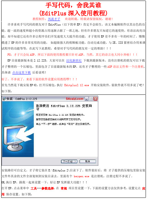
EP目前最新版本是2.12.225,大家可以在汉化新世纪下载到最新版本,没有注册机的朋友可以下载才子整理的一个压缩包,里面包含了目前最新版本的EP,还有才子整理的一些ASP语法文件和一个注册机,具体请点击这里下载后看说明!
#TITLE=ASP
#CASE=n
#T=setconn
Set conn = Server.CreateObject("ADODB.Connection")
#T=connopen
Conn.Open "Provider=Microsoft.Jet.OLEDB.4.0;Data Source=" & Server.MapPath(DB)
再切换到语法子项里,添加一个ASP的语法,这里是重点,仔细看,具体文件的使用方法将在后面介绍,先看设置如下图:
自动换行及制表符/缩进随你自己喜欢设置吧,才子反正是喜欢自动换行,缩进设置成4,仅供参考!如下图:
再切换到模板子项里,添加一个ASP的初始模板吧,以后只要新建一个ASP文件,就会自动帮你加上你模板中预设的内容,等会才子会在后面说明模板文件的使用方法,先看下面的添加方法,如下图:
好了,下面就是EP最重要的功能之一了,与IE、IIS的结合,首先,先在IIS里设置成主目录为D:\MyHomePage,这是不截图了,再在工具选项里添加Web服务器根目录,添加方法如下图:
才子这里的D:\MyHomePage是才子设置的一个主目录,里面就随便弄一个default.asp文件吧,随便写点内容如下:
OK,执行EP,跟我一起来设置一下,好让EP发挥最大功能!!!
打开EP,点击菜单中工具---参数选择,在常规项目里设置一下,下面的设置方法仅供参考,设置完点应用保存设置。如下图:
ESPS用户操作手册
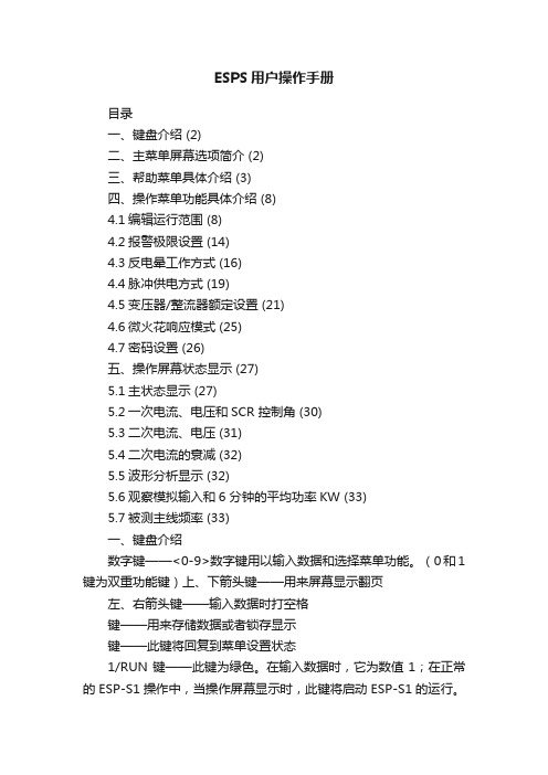
ESPS用户操作手册目录一、键盘介绍 (2)二、主菜单屏幕选项简介 (2)三、帮助菜单具体介绍 (3)四、操作菜单功能具体介绍 (8)4.1编辑运行范围 (8)4.2报警极限设置 (14)4.3反电晕工作方式 (16)4.4脉冲供电方式 (19)4.5变压器/整流器额定设置 (21)4.6微火花响应模式 (25)4.7密码设置 (26)五、操作屏幕状态显示 (27)5.1主状态显示 (27)5.2一次电流、电压和SCR 控制角 (30)5.3二次电流、电压 (31)5.4二次电流的衰减 (32)5.5波形分析显示 (32)5.6观察模拟输入和6 分钟的平均功率KW (33)5.7被测主线频率 (33)一、键盘介绍数字键——<0-9>数字键用以输入数据和选择菜单功能。
(0和1键为双重功能键)上、下箭头键——用来屏幕显示翻页左、右箭头键——输入数据时打空格键——用来存储数据或者锁存显示键——此键将回复到菜单设置状态1/RUN键——此键为绿色。
在输入数据时,它为数值1;在正常的ESP-S1操作中,当操作屏幕显示时,此键将启动ESP-S1的运行。
如ESP-S1已经处在工作状态,此键将重新启动斜率搜索。
HALT键——此键为红色。
在输入数据时,它为数值0;在正常ESP-S1操作中,当操作屏幕显示时,按下此键将会使火花消失,从而使ESP-S1操作停止,如ESP-S1已经处于报警停滞状态,按此键可消除报警。
键——在输入数据时,此键用来储存输入的数据和设置。
在正常ESP-S1操作中,按此键将锁存主要状态显示《DISPLAY HOLD》30秒钟,以便于操作人员记录读数。
运行中按此键将不会影响控制系统的工作。
二、主菜单屏幕选项简介ESP-S1共有三个主菜单屏幕,操作人员可以获取所有的控制功能和帮助菜单。
在主菜单显示的情况下,按下相应的数字键即可进入不同的操作。
我们先对每个操作选项加以简单的介绍。
系统通电后在键盘按下键,即可从主菜单进入第一主菜单(ESP-S1 Main Menu 1),此菜单具体选项如下:1、帮助菜单(Help Menu)——进入帮助菜单显示,这里可以帮助您解决在实际操作应用中遇到的个中问题。
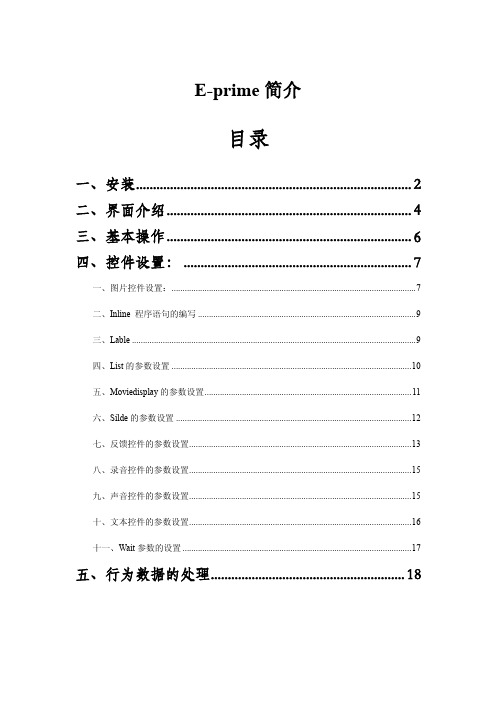
e-prime软件基本操作
在此注册,输入用户名和公司单位以及序列号,序列号格式如:4198A5-8D7E92-9E89BD。 e-prime1.0 在安装的时候需要插上狗才可以安装,而 2.0 不需要。
打开软件的界面如图:
二、界面介绍
菜单栏
快捷方式 结构视窗
属性视窗
工具箱
工作区
嵌入图片刺激 实现程序语句
设置标签 表单
五、Moviedisplay 的参数设置
①Filename 文件路径 ②Tart position 开始时间 ③Stop position 结束时间 ④Back color 背景颜色 ⑤Back style 背景风格 ⑥Streth 是否拉伸和屏幕匹配 ⑦End movie action 结束方式(terminate 视频播放完结束 jump 播放完跳转) 其它界面参数设置和图片控件类似不再详述
三、Lable
设置一个标签,在符合某一条件跳转到此
四、List 的参数设置
打开
会出现界面如下:
增加一行 增加多行 增加一列 增加多列 隐藏 summary List 呈现格式 删除行 删除列
Order 一般常用的有两种调取方式 sequential 顺序方式和 random 随机方式 另外还有一些参数界面如图:
六、Silde 的参数设置
打开
之后:
ActiveState 选择激活的 slide 项
具体功能与上边雷同不再赘述。 是各个控件的呈现格式不再赘述。 是加入一个文本控件 是加入一个图片控件 是加入一个视频控件 是加入一个声音控件 是加入一个录音控件
七、反馈控件的参数设置
打开 之后:
①Input object name 选择需要反馈的对象 ②Collect ACC stats 采集正确反应类型 ③Collect no response ACC stats 采集反应不正确类型 ④Collect correct RT stats 采集正确反应时间 ⑤Collect incorrect RT stats 采集反应不正确类型
数字信号控制e-WriterPro烧录之使用手册

图5 b) 在 EXTG 引脚上加入一低脉冲即开始进行烧录,如图 4 中的 T1(此动作等同于按下 e-WriterPro 上红色烧录键) c) 承b,可持续对EOP引脚进行轮询,若获得一低脉冲,如上图T2,则代表烧录已完成 d) 在EOP低脉冲期间(即上图T2期间),检查BIN1~BIN7等引脚的状态可得知烧录情况,如BIN1在 T2区间为低代表烧录成功,而BIN4在T2区间为低代表烧录失败,原因为IC非空
数字信号控制e-WriterPro烧录
使用手册
本资料版权为盛群半导体股份有限公司所有,非经盛群半导体股份有限公司书面授权同意,不得通过任何形 式复制、储存或传输。
内容
内容
1. 概要 .................................................................................................................................................................2 2. 方式一:外接烧录按钮 .................................................................................................................................2 3. 方式二:数字信号控制 .................................................................................................................................3 附录. e-WriterPro CN3 脚位定义图表..............................................................................................................5
e-prime新手教程,step by step教你如何使用e-prime,新手入门型
E-Prime使用说明简介E-Prime有许多功能,包括编写程序(E-Studio)、执行程序(E-Run)、整理data(E-DataAid)、修复data(E-Recovery)、合并data(E-Merge)。
一般来说,要编写程序我们会使用E-Studio。
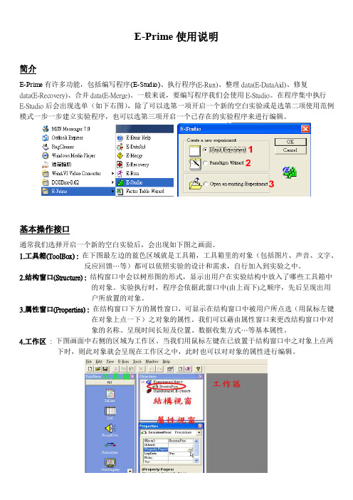
在程序集中执行E-Studio后会出现选单(如下右图),除了可以选第一项开启一个新的空白实验或是选第二项使用范例模式一步一步建立实验程序,也可以选第三项开启一个已存在的实验程序来进行编辑。
基本操作接口通常我们选择开启一个新的空白实验后,会出现如下图之画面。
1.工具箱(ToolBox) : 在下图最左边的蓝色区域就是工具箱,工具箱里的对象(包括图片、声音、文字、反应回馈…等)都可以依照实验的设计和需求,自行加入到实验之中。
2.结构窗口(Structure) : 结构窗口中会以树形图的形式,显示出用户在实验结构中放入了哪些工具箱中的对象。
实验执行时,程序会依据此窗口中(由上而下)之顺序,先后呈现出用户所放置的对象。
3.属性窗口(Properties) :在结构窗口下方的属性窗口,可显示在结构窗口中被用户所点选(用鼠标左键在对象上点一下)之对象的属性。
我们可以藉由属性窗口来更改结构窗口中对象的名称、呈现时间长短及位置、数据收集方式…等基本属性。
4.工作区: 下图画面中右侧的区域为工作区。
当我们用鼠标左键在已放置于结构窗口中之对象上点两下时,则此对象就会呈现在工作区之中,此时也可以对对象的属性进行编辑。
编辑实验程序举例说明假设我们现在的实验,想请受试者先看一个中文字中的部件(如:言),再看一个中文字(如:试),并请受试者判断先前看到的部件,是否有出现在后来看到的中文字中。
因此,本实验的呈现顺序为: 指导语画面→练习开始画面→练习(5个trial)→练习结束画面→正式实验(10个trial)→实验结束画面练习trial为:哔声→部件→遮蔽(mask)→中文字→回馈→全黑画面正式实验trial为:哔声→部件→遮蔽(mask)→中文字→全黑画面开始编辑1.时间轴:首先,在SessionProc图标上按鼠标左键一下,会出现属性窗口。
易飞ERP系统作业操作手册
易飞系统作业操作手册目录第一章基本作业操作____________________________________3第一节主画面基本操作_____________________________________3第二节录入作业基本操作___________________________________4第三节打印凭证基本操作___________________________________10第四节报表基本操作_______________________________________13第二章品号与BOM 信息的建立___________________________18第一节品号资料的建立_____________________________________ 18第二节BOM 资料的建立____________________________________24第三节相关报表的查询及列印________________________________27第三章客户订单至生成批次需求计划_______________________28第一节设置订单单据性质____________________________________28第二节客户信息资料的建立__________________________________29第三节报价单的录入________________________________________30第四节客户商品价格的录入__________________________________31第五节客户订单资料的录入__________________________________32第六节订单变更单的录入____________________________________33第七节生成批次需求计划维护及锁定__________________________34第八节发放LRP采购单______________________________________37第九节发放LRP工单_________________________________________38第十节相关报表的查询及列印________________________________39第四章请购单至采购进货_________________________________40第一节设置采购单单据性质__________________________________40第二节供应商信息资料建立__________________________________41第三节采购核价单的录入____________________________________42第四节供应商料件价格的录入________________________________43第五节请购单资料的建立____________________________________44第六节维护请购信息作业____________________________________45第七节从请购单生成采购单__________________________________46第八节采购单资料的建立____________________________________47第九节采购变更单的录入____________________________________48第十节采购进货单的录入____________________________________49第十一节采购退货单的录入__________________________________51第十二节相关报表的查询及列印______________________________52第五章工单至入库及委外进、退货_________________________53第一节设置工单单据性质___________________________________53第二节委外核价单的录入___________________________________54第三节委外价格的录入_____________________________________55第四节工单资料的建立_____________________________________56第五节工单变更单的录入___________________________________58第六节领、补料单及超领单的录入__________________________59第七节退料单的录入_______________________________________61第八节生产入库单的录入___________________________________63第九节委外进货单的录入___________________________________64第十节委外退货单的录入___________________________________65第十一节相关报表的查询及列印_____________________________66第六章客户订单至销货___________________________________67第一节出货通知单的录入___________________________________67第二节销货单的录入_______________________________________68第三节销退单的录入_______________________________________69第四节相关报表的查询及列印_______________________________70附表易飞系统作业流程图_______________________71第一章 基本作业操作第一节 主画面基本操作<主画面>双击¡易飞ERP 系统¡,图标找开系统登录画面选择公司名称(即套帐名称) 功能设置-第二节录入作业基本操作<主画面>1. 新增:在数据库中新增一笔信息,选择新增功能钮后,将进入信息新增状态。
e-Writer烧录器使用手册

e-Writer系列烧录器使用手册

e-Writer( ) (HOPE3000) ( e-Writer e-Writer 4P Jumper [ 4P DIP Switch ] )HOPE3000 HOPE3000 HOPE3000 HOPE3000HOPE3000 MS Windows HOPE3000 – DOS Command Modee-WriterPro LCD e-Writer plus e-monitor( LCM ) e-monitor e-monitorA HOPE3000 e-monitorBC e-Writer e-WriterD e-WriterPro ICP ICP ICPE e-WriterPro CN3 CN3 e-WriterPro( Writer) e-Writer e-Writer e-Writer plus e-WriterPro e-Writer e-Writer e-Writer plus e-Writer plus e-WriterPro e-WriterPro1.00 2009/03/111.01 2009/04/301.02 2009/06/151.03 2009/10/15 1. HOPE30002. HOPE30003. N-14.1.04 2010/01/20 Memory IC1.05 2010/04/29 1. e-Writer plus2. Memory IC3. HOPE30004.1.06 2011/01/12 1. ( )2. Dos Command Mode T3. Dos Command Mode E SPI Flash4. Pin Configuration5. DOS -C6. Dos Command –D EEPROM (.MEM) MCUEEPROM1.07 2011/01/14 1. Dos Command Mode P V B2.HOPE30001.08 2011/05/06 e-WriterPro1.09 2012/05/30 1. Dos Command Mode D IC2. Dos Command Mode S1.10 2012/07/10 1. ICP ( Case11) ICP ( D)2. HOPE3000 IC3. HOPE3000 V1.04 ( )4. e-WriterPro CN3 ( E)5. HOPE30001.11 2013/05/22 1. Case3 IC2.Dos Command Mode console CON Q1.12 2013/12/23 (6) (7) (7) (10) (10) (14) (17) (17)Case. 1 – MCU (17)Case. 2 – (19)IC (21)Case. 3 –Case. 4 – (23)Case. 5 – (25)Case. 6 – IC ( ) (26)Case. 7 – (28)Case. 8 – PC (Firmware) (29)Case. 9 – (31)Case. 10 – e-WriterPro (35)Case. 11 – e-WriterPro ICP(In-Circuit Programing) (37)HOPE3000 (38) (39) (39) (39) (39) (40) (40) (41) (42) (43) (44) (45)IC (45)HOPE3000 (46)IC (47) (47) (48) (49) (50) (52)HOPE3000 – Dos Command Mode (56) (56) (57) (62)e-monitor (64)e-monitor (65)e-monitor (66)e-monitor (67)e-monitor (67)A (70) (70)Writer (73)e-monitor (75)B (78)C e-Writer (79)D e-WriterPro ICP ICP (81)E e-WriterPro CN3 (87)e-Writer ( ) (MCU) OTP/Flash MCU(Program) (Data)PC PC PC HOPE3000 PC USB cable PC HOPE3000MCU MCU e-WriterPro e-Socket e-Writer e-Writer plus (Adaptor)( Writer) e-Writer e-Writer e-Writer plus e-WriterPro e-Writer e-Writer e-Writer plus e-Writer plus e-WriterPro e-WriterPro1USB Port (PC)( )MS Windows 2000/XP ( ) HOPE3000 ( )e-WriterPro1-1e-Writer pluse-Writer plus ( 1-2) ( 1-3)1-21-3e-Writer1-41. e-monitor – LCM e-Writer plus 6 e-monitor1-5USB cable USB ( 1-6) e-Writere-Writer 4P Jumper ( 4P DIP Switch) ( 1-1 )1-61HOPE3000 “HOPE3000V304Build20120316Install.EXE” ( release )2( 1-7) (Next)1-73HOPE3000 ( 1-8) (Next)1-84( 1-9) (Next)1-95( 1-10) (Next)1-106Install ( 1-11)1-117Finish ( 1-12)1-121-13(e-WriterPro) 1-14(e-Writer plus) 1-15(e-Writer)1-21-141-13LCD: e-Writer 4P DIP Switch 1-13OKReady/Busy /FailUSB USB PC( )5V ( )4P Jumper (DIP Switch) ( ) 1e-WriterDC 9V~16V DC e-Writer plus e-monitor e-monitor e-Writer plus LCD e-WriterPro LCD e-WriterPro Handler Handler e-WriterPro e-WriterPro 1 4P Jumper ( 4P DIP Switch) Short (Switch ON) SPIFlash MCU( HT83Fxx) OTP/Flash MCU Open1-151-16(Switch OFF)e-Writer4P Jumper ( 4P DIP Switch)1-2e-Writer/e-Writer plus 1-3e-WriterPro PinAD0 (ICPDA)8 HT46&HT48 Flash MCU AD1 (ICPDA) 6 HT46&HT48Flash MCUAD2 4AD3 2CLK (ICPCK)10CSB 12RWB 14SCL 3SDA 5VDD 18VPP20SCK 9 1SDI 11 2SDO 13 3CEB 15 4Ground (direct connection)16 17 19(VSS)1: 4P Jumper Jumper 4 Short = SCK , Open = Ground (direct connection)) (4P DIP Switch DIP 4 ON = SCK , OFF = Ground (direct connection))2: 4P Jumper Jumper 3 Short = SDI , Open = Ground (direct connection)(4P DIP Switch DIP 3 ON = SDI , OFF = Ground (direct connection))3: 4P Jumper Jumper 2 Short = SDO , Open= Ground (direct connection)(4P DIP Switch DIP 2 ON = SDO , OFF = Ground (direct connection))4: 4P Jumper Jumper 1 Short = CEB, Open = Ground (direct connection)(4P DIP Switch DIP 1 ON = CEB, OFF = Ground (direct connection))1-32MCU HT-IDE3000 Project Build MCU (.OTP/.MTP/.PND.. ) HOPE3000 MCU HT-IDE3000 HT-IDE3000PC HOPE3000MCUCase. 1 –PC MCU (.OTP/.MTP/.PND) MCU 1HOPE3000 / / ( 2-1)2-122-2 (OTP MTP PND)( 1) ( 2) ( 3)2-23( \ \ ) 2-32-3e-WriterPro ( 2-4)2-44( 2-5)2-4 IC ( IC ) Flash MCU MCU3 HOPE3000A2-5Case. 2 –Case. 1 PC HOPE3000 PC1 ~ 3Case. 1 1~342-6 2-75( 2-7) ( 1 2)( 3)2-62-762-7 ( )3 HOPE30004 HOPE3000AICCase. 3 –IC1 ~ 4Case. 2 1~452-8 ( 1) ----> ( 2) ( 3) Code( 4) ( 5) 2-92-862-9 ( 1) ROM ( 2) ( 3) ( 4)2-975~6 IC 2-10 ( 1) ( 2)3 HOPE30004 HOPE3000A2-10Case. 4 –Program ROM1~4Case. 2 1~452-11 1~3 ( 4) 2-1262-12 IC Program ROM 100H N+1 N 22( IC 22 23 …) 1~32-12 HOPE30002-1272-13 1 2 ( 3) 22-13Case 33 HOPE30004 HOPE3000ACase. 5 –( PC ) PC1~5Case2 1~56HOPE3000 PC USB71~5 (Ready LED ) (Fail LED ) ( 1~5)LED (Ready )8IC( 1~5 MCU ) ( 1-13~1-15 )9LED ( / LED LED )e-WriterPro e-Writer e-Writer plus3 HOPE30004 HOPE3000ABIC (Case. 6 –)IC IC IC IC IC HOPE3000 IC1/ / IC 2-142-142IC IC IC( 2-15)2-15e-WriterPro ( 2-16)2-163HOPE3000 IC Driver 2-17 IC / / IC HOPE30002-17HOPE3000 A Case. 7 –HOPE3000 DOS Command Mode1HOPE3000 Microsoft Windows HOPE3000 DOS Command Mode2HOPE3000 ( 3 ) DOS Command Mode WCMD.EXE ( 2-18)2-183DOS Command Mode ( 2-19 )2-19DOS Command Mode HOPE3000 - Dos Command Mode A(Firmware)Case. 8 – PCe-Writer plus( ) PC HOPE3000 ( HOPE3000 )e-Writere-Writer plus e-WriterProPC1/ /F/W ( 2-20 )2-2022-212-2132-222-23 HOPE3000 2-234F/W ( 2-24) HOPE30002-24HOPE3000 ACase. 9 –e-WriterProe-WriterProe-Writer e-Writer plus1/ /2-252-2522-26 ID62-2632-27 e-Mail( )HOLTEK2-2742-28 2-27 3 HOLTEK2-285HOLTEK e-Writer Pro Registry Key2-292-30 ( )2-306HOPE3000 ( 2-31 1)2-3172-326 1 HOLTEK2-32HOPE3000 ACase. 10 – e-WriterProe-WriterPro e-WriterPro e-WriterPro e-WriterPro e-WriterPro< 1>e-WriterPro CN3 Pin2/Pin4 2-33 2-342-332-34< 2>e-WriterPro 2-351)2-35E – e-WriterPro CN3 BIN1~BIN7 Pin & 42) &2-36T1 e-WriterPro 10ms < T1 < 500msT2 e-WriterPro 12ms < T2 < 100ms1) e-WriterPro J7( 3-37 ) e-WriterPro2-372) EXTG Pin 2-36 T1(e-WriterPro )3) 2 EOP Pin (Polling) 2-36 T24) EOP ( 2-36 T2 ) BIN1~BIN7 PinBIN1 T2 (Low) BIN4 T2 ICe-WriterPro ICP(In-Circuit Programing)Case. 11 –e-WriterPro ICP1ICP (e-WriterPro 1-1) e-WriterPro CN1( D – e-WriterPro ICP ICP )2HOPE3000 (.OTP/.MTP/.PND) / /32-38 ICP( D e-WriterPro ICP ICP 2-38 ICP HOPE3000 )2-384/ / …HOPE3000 De-WriterPro ICP ICPHOPE3000 HOPE3000 IC ( PC ) 3-13-13( 3-2 )OTP (OTP MCU)MTP (Flash MCU)PND (MCU with SPI Flash)APF (Advanced Programming File )R36 (HT81R36 )ICIC IC IC IC 3-12 IC( ) HOPE3000HOPE3000 ( )HOPE3000HEXHOPE3000 Intel HEXHOPE3000/ / (3-3)( 3-4)/ ICe-WriterPro IC / /3-33-2HOPE3000// /( 3-5 )F/WPC Case. 8 PC OptionIC OptionHT-IDE3000 ( )/ /( 3-6 )e-WriterIC ICHOPE3000 3-7 1 HOPE3000 Release Driver 2 (Firmware) ID3-73-5 3-63-4Code( Program), Option, Data, Voice ROM 3-8 ROM ROM ---- IC ROM ( ) HOPE3000 HOPE3000ROMHOPE3000ROM , / IC HOPE3000 HOPE30003-8( 3-9)IC Windows 0( ) F/W( e-WriterPro)3-93-10 DriverDriver Driver( ) Driver IC / / IC IC 3-10 Driver HT45F0V Driver 1.0 Driver IC Driver IC IC Driver DriverROM ROM Code Code Code + Option Code Option Code + Option + Data Code Option Data OTP/MTP/PNDV1.04 ( ) V1.04 ROMV1.04( ) ( ) Option ROM TRIM (HIRC/LVR .. ) ROM ( IC TRIM IC HOPE3000 IC IC TRIM ) 3-10( IC ) 3-11IC ( IC )IC IC ICIC IC IC IC ICIC IC Flash Type MCU ICIC / / HOPE3000 HOPE3000 ( ) / /HOPE3000Flash Type MCU ICDataData ROM IC SPI Flash MCU( HT83Fxx) ( IC SPI Flash) IDIC 3-11IC ( IC ) OTP MCUIC / / IC ( 3-12) IC ICIC IC IC ( 3-12 HT45R0F ) ICICIC3-12HOPE3000 HOPE3000 ( PC IC ) ( PC ) ( ) 4-14-1 4ICIC ( 4-2 )Driver HOPE3000 Driver IC \ \ IC ICHOPE3000 IC 04-2( 4-3)(.SPC)(.SPC)HOPE30004-3( ) ( ) ( 4-4)4-4ID — HOPE3000 IDIC OTP MCU ICIC ( IC ) -----> <-----4-4 Code Optiion Data Voice —IC Code Option Data Voice ROM Code Voice( 4-6) ( 4-4 Voice) IC ROM—( 4-9)4-5( )4-5。
e-multi 控制器使用手册说明书

控制器使用手册第3版目录第一章简介............................................................................................................. 1-1 1.1预期用途........................................................................................................... 1-1 1.2版本信息........................................................................................................... 1-1 1.3保修详情........................................................................................................... 1-1 1.4退货政策........................................................................................................... 1-1 1.5模具主产品或系统的移动或转售................................................................... 1-1 1.6版权................................................................................................................... 1-2 1.7计量单位和换算系数....................................................................................... 1-2第二章全球支持...................................................................................................... 2-1 2.1生产基地及各地办公室................................................................................... 2-1 2.2其他各国........................................................................................................... 2-2第三章安全............................................................................................................. 3-1 3.1简介................................................................................................................... 3-1 3.2安全隐患........................................................................................................... 3-2 3.3操作危险........................................................................................................... 3-5 3.4一般安全标识................................................................................................... 3-6 3.5缆线检查........................................................................................................... 3-7 3.6锁定安全........................................................................................................... 3-8 3.7接地连接......................................................................................................... 3-11 3.8处理................................................................................................................. 3-11 3.9E-Multi控制器安全隐患 ............................................................................... 3-12 3.10E-Multi 注塑单元安全隐患标注 .................................................................. 3-14 3.11E-Multi 注塑单元安全隐患标注 .................................................................. 3-15 3.12E-Multi 注塑单元上的安全标识 .................................................................. 3-17 3.13E-Multi 注塑单元安全防护 .......................................................................... 3-18 3.14E-Multi 注塑单元注塑规格 .......................................................................... 3-19 3.15打开E-Multi控制器的包装 .......................................................................... 3-20 3.16吊装E-Multi控制器 ...................................................................................... 3-22 3.17吊装E-Multi注塑单元 .................................................................................. 3-24 3.18EM1/ EM2 / EM3吊装连接.......................................................................... 3-25 3.19E-Multi 注塑单元的安全标准 ...................................................................... 3-27第四章概览............................................................................................................. 4-1 4.1控制器前侧....................................................................................................... 4-1 4.2控制器后侧–连接面..................................................................................... 4-2 4.3线缆支架........................................................................................................... 4-3第五章安装............................................................................................................. 5-1 5.1介绍................................................................................................................... 5-1 5.2将控制器连接至E-Multi .................................................................................. 5-2 5.3连接至机器人................................................................................................... 5-2 5.4控制器与注塑机的连接................................................................................... 5-3 5.5连接至手持HMI(选配) .................................................................................... 5-4第六章操作............................................................................................................. 6-1 6.1简介................................................................................................................... 6-1 6.2断开控制器....................................................................................................... 6-1 6.3打开................................................................................................................... 6-2 6.4关闭................................................................................................................... 6-2第7章- E-Multi控制器屏幕界面 ............................................................................ 7-1 7.1 介绍................................................................................................................... 7-1 7.2 机箱控制按钮................................................................................................... 7-2 7.3 E-Multi 触摸屏界面......................................................................................... 7-3 7.4 界面描述........................................................................................................... 7-8 7.5 概览界面........................................................................................................... 7-9 7.6 注塑设置界面................................................................................................. 7-13 7.7 保压设置界面................................................................................................. 7-16 7.8 恢复设置界面................................................................................................. 7-18 7.9 料筒温度控制–传统控制器* ..................................................................... 7-21 7.10 料筒温度设置- Mold-Masters界面............................................................. 7-23 7.11 集成热流道温度控制(选配)..................................................................... 7-26 7.12 集成E-Drive控制(选配) ........................................................................... 7-37 7.13 总览界面......................................................................................................... 7-39 7.14 设置界面(主管级别)................................................................................. 7-41 7.15 阀浇口设置界面............................................................................................. 7-43 7.16 喷嘴闭合设置界面......................................................................................... 7-45 7.17 闭合喷嘴设置界面—Kortec .......................................................................... 7-48 7.18 生产图界面..................................................................................................... 7-51 7.19 软件示波器..................................................................................................... 7-54 7.20 加工数据(PD) 表格界面.............................................................................. 7-57 7.21 主设置界面..................................................................................................... 7-59 7.22 系统设置界面................................................................................................. 7-61 7.23 E-Multi 旋转/伺服托架界面 ......................................................................... 7-64 7.24 自动清洁界面................................................................................................. 7-66 7.25 信息日志界面................................................................................................. 7-68 7.26 可编程输入/输出(I/O) ............................................................................ 7-70 7.27 生产设置界面................................................................................................. 7-73 7.28 驱动器监控界面............................................................................................. 7-74 7.29 任务监控界面................................................................................................. 7-76 7.30 驱动参数监控界面......................................................................................... 7-77 7.31 PID 设置 ......................................................................................................... 7-78 7.32 参考设置界面................................................................................................. 7-79 7.33 机器数据界面................................................................................................. 7-81 7.34 变量监视器界面............................................................................................. 7-82 7.35 延时设置界面................................................................................................. 7-84 7.36 校准设置界面................................................................................................. 7-85 7.37 报警界面......................................................................................................... 7-867.39 Euromap E67界面 .......................................................................................... 7-90 7.40 传统E67界面................................................................................................ 7-91 第八章维护保养...................................................................................................... 8-1 8.1清洁HMI屏幕.................................................................................................. 8-1 8.2预防性维护....................................................................................................... 8-1 8.3检查注塑压力油路(预加载压力)............................................................... 8-2 8.4喷嘴伸出调整-自动调整.................................................................................. 8-3 8.5注塑轴参考....................................................................................................... 8-5 8.6保养和维修您的控制器................................................................................... 8-6 8.7更新软件........................................................................................................... 8-7第九章故障诊断...................................................................................................... 9-1 9.1感温线电气检查............................................................................................... 9-1 9.2加热器连续性检查........................................................................................... 9-1 9.3传感器输出检查............................................................................................... 9-1 9.4振动器阀门检测............................................................................................... 9-1 9.5伺服电机温度检查........................................................................................... 9-2 9.6控制系统故障排除........................................................................................... 9-2第一章简介本手册的目的是帮助用户整合、操作和维护E-Multi控制器。
E版-3.9.0操作手册
目录目录 0第一章:系统概要 (2)第二章:系统结构 (3)第一节:网络拓扑图 (3)第二节:功能模块 (3)第三章:系统操作 (3)第一模块:登录系统 (4)第二模块:节目管理 (4)第一节:制作节目 (4)第一要素:编辑器 (4)1、新版编辑器 (4)2、旧版编辑器 (6)第二要素:节目制作 (8)1、名词介绍 (8)2、制作(旧版编辑器为例) (8)2。
1文字插入功能 (8)2。
1。
1静态文字使用方法 (8)2.1.2动态滚动字幕使用方法 (8)2.2图片插入功能 (9)2。
2.1背景图片使用方法 (9)2。
2。
2普通图片使用方法 (9)2.2.3广告图片使用方法 (10)2.2.4 Logo图片使用方法 (10)2。
3视频插入功能 (10)2。
3。
1 Flash动画插入使用方法 (10)2。
3。
2自动播放媒体插入使用方法 (11)2。
3。
3视频直播使用方法 (11)2。
4日期时间插入功能 (11)2。
5倒计时和正计时插入功能 (11)2.5.1倒计时使用方法 (11)2。
5.2正计时使用方法 (11)2.6 Office组件插入功能 (12)2。
7数据采集组件插入功能 (12)2.8天气预报插入功能 (12)2.9触摸卡片的使用方法 (12)2。
9。
1 摘要卡片 (12)2。
9。
2 图片卡片 (13)2.9.3 视频卡片 (13)2.10 选择模版功能 (13)2。
11播放时间设置 (13)2.12框架节目(互动节目)的制作 (13)2。
13插入按钮的使用方法 (13)2。
14 保存、新建场景、生成节目与预览 (14)第三节:节目管理界面 (14)第四节:节目发布设置 (15)第五节:节目审批 (16)第六节:下载管理 (16)第七节:删除节目 (16)第一要素:终端节目删除 (16)第二要素:管理端节目删除 (17)第八节:节目备份 (17)第九节:节目发布界面 (17)第十节:节目审批界面 (18)第三模块:终端管理 (18)第一节:插播消息 (18)第二节:终端信息管理 (18)第三节:终端监控管理 (19)第四节:终端带宽管理 (20)第五节:终端升级 (20)第四模块:系统设置 (20)第一节:权限管理 (20)第一要素:机构管理 (21)第二要素:角色管理 (21)第三要素:用户管理 (21)第二节:分发服务器管理 (22)第三节:数据采集服务 (22)第一要素:数据采集服务 (22)第四节:参数设置 (22)数据组件节目制作 (23)第五节个性化 (23)第五模块:系统日志 (24)第一节:用户操作日志 (24)第二节:播放日报表 (24)第三节:素材统计表 (24)第六模块:素材管理 (24)第一节:素材管理 (24)第一要素:素材上传 (24)大文件上传 (25)第二节:模版管理 (25)第一要素:背景模板 (25)第二要素:普通模板 (25)第三节:在线资源 (26)多媒体信息发布系统V3。
eprime操作.docx
E-Prime 使用明 1是一份老我的学料,是从网上找到的,在把它放上来,算作。
通自篇文章,用两三个小的你可以基本理解 E-Prime 的使用方法和程。
介E-Prime 有多功能,包括写程序 (E-Studio) 、行程序 (E-Run) 、整理data(E-DataAid) 、修复 data(E-Recovery) 、合并 data(E-Merge) 。
一般来,要写程序我会使用 E-Studio 。
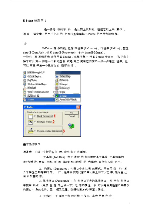
在程序集中行 E-Studio 后会出(如下右),除了可以第一开启一个新的空白或是第二使用范例模式一步一步建立程序,也可以第三开启一个已存在的程序来行。
基本操作接口通常我开启一个新的空白后,会出如下之画面。
1.工具箱 (ToolBox) : 在下最左的色区域就是工具箱,工具箱里的象(包括片、声音、文字、反回⋯等)都可以依照的和需求,自行加入到之中。
2.构窗口 (Structure) : 构窗口中会以形的形式,示出用在构中放入了哪些工具箱中的象。
行,程序会依据此窗口中 ( 由上而下 ) 之序,先后呈出用所放置的象。
3. 属性窗口 (Properties) : 在构窗口下方的属性窗口,可示在构窗口中被用所点(用鼠左在象上点一下)之象的属性。
我可以藉由属性窗口来更改构窗口中象的名称、呈短及位置、数据收集方式⋯等基本属性。
4.工作区 : 下画面中右的区域工作区。
当我用鼠左在已放置于结构窗口中之对象上点两下时,则此对象就会呈现在工作区之中,此时也可以对对象的属性进行编辑。
编辑实验程序举例说明假设我们现在的实验,想请受试者先看一个中文字中的部件(如:言),再看一个中文字(如:试),并请受试者判断先前看到的部件,是否有出现在后来看到的中文字中。
因此,本实验的呈现顺序为:指导语画面→练习开始画面→练习(5 个 trial)→练习结束画面→正式实验(10 个 trial)→实验结束画面练习 trial为:哔声→部件→遮蔽(mask)→中文字→回馈→全黑画面正式实验 trial为:哔声→部件→遮蔽(mask)→中文字→全黑画面开始编辑1.时间轴 : 首先,在 SessionProc 图标上按鼠标左键一下,会出现属性窗口。
E-Prime使用教程(PPT-58)教学文稿

❖实验材பைடு நூலகம்:
序号 启动词
1
市
2
市
3
巾
4
巾
词对 之一
省 省 省 省
词对 之二
县 层 县 层
答案
K d K d
水平
YY YN NY NN
E-Prime实验设计:
实验的运行
❖ 编译:把在E-Studio中设计调试好的实验 ,进行编译,生成同名的脚 本文件 。
❖ 脚本文件:把脚本文件拷入到需要实验的计算机上【该机器必须装有E -Prime环境(E-Run)】,或单机或共享使用,即可运行实验。
PST 公司还专门开发了与E-Prime 配套的反应盒SRBOX和自控灵敏度的话筒, SRBOX有5个反应键,分别对应于5 种颜色的小灯泡(红、白、蓝、绿、黄)相 对于普通键盘和鼠标反应,SRBox 的响应延迟时间很短,约为1.25ms。除了按 键和鼠标反应外, E-Prime系统还支持用自控灵敏度的话筒进行言语反应、以 及脚键反应。
S tim ( D R /K B & S D /R T & C R )
f e e d b
前面:指导语
后面:实验完毕,感谢语
E-Prime实验设计:
设计前准备--画出实验流程图
一个完整的实验
Block
指 导 语 +( D R /K B & S S ti D m /R T & C R ) f e e d b 结 语
Run:运行。在设计环境下运行所设 计好的程序或运行生成的脚本文件。
程序界面:
E-Merge – 构成和功能
E2Merge 是E2Prime 系统中一个关于数据处理的扩 展功能。通过使用E2Merge ,研究者可以把多个数据 文件快速、简单地合并,形成一个独立的数据文件,避 免每次只能打开一个数据文件的情况。
明基EZWrite 4.1 Lite 用户手册说明书

User ManualDisclaimerBenQ Corporation makes no representations or warranties, either expressed orimplied, with respect to the contents of this document. BenQ Corporation reserves the right to revise this publication and to make changes from time to time in the contentsthereof without obligation to notify any person of such revision or changes. CopyrightCopyright 2018 BenQ Corporation. All rights reserved. No part of this publication may be reproduced, transmitted, transcribed, stored in a retrieval system or translated into any language or computer language, in any form or by any means, electronic, mechanical, magnetic, optical, chemical, manual or otherwise, without the prior written permission of BenQ Corporation.Table of Contents i T able of Contents Introduction (1)Annotation (3)Palm eraser (5)Handwriting recognition (6)Selecting and modifying texts (10)T ool box (11)Stopwatch (12)Timer (13)Scoreboard (14)Draw (15)Importing images (16)Adding pages (17)Saving files (18)Wallpaper (19)Wireless sharing (20)QR code (20)InstaQPrint (20)Floating Annotation T oolbar (22)Setting (23)How to upgrade EZWrite (24)Comparison T able (25)4/30/18Introduction 1IntroductionEZWrite 4.1 is a writing and annotation application that allows you to treat the touchscreen like an interactive, multi-functional blackboard/whiteboard. EZWrite 4.1 supports 10-point touch.Function DescriptionExitClick to exit EZWrite 4.1.Save Click to save the drawings or annotations shown on thescreen. Refer to Saving files on page 18 for moreinformation.Share Click to share the file via QR code or Print . Refer toWireless sharing on page 20 for more information.ChangeBackground Click to change the background for EZWrite 4.1. ReferWallpaper on page 19 for more information.Select Click to select multi-objects. Refer to Selecting andmodifying texts on page 10 for more information.Pen T wo pen types are provided: Brush and Dual Pen. Referto Annotation on page 3 for more information.EraserClick clear all to erase all drawings/annotations on thescreen. Click circle erase to erase the handwriting in thecircle.Introduction2 T ool Box Click to choose from different tools. Refer to T ool boxon page 11 for more information.Import Files Click to import an image or text file into EZWrite 4.1.Refer to Importing images on page 16 for moreinformation.Undo Click to undo the previous operation.Redo Click to redo the cancelled operation.Add new page Click to add a new page of writing image. Refer toAdding pages on page 17 for more information.Page Reveals the page number of the current picture. Click toview the list of pages. Refer to Adding pages on page 17for more information.All functions in this manual vary by models. Details are listed on the last page.Annotation 3Annotation Click in EZWrite 4.1 to set brush type, color, and thickness. T wo other special types are provided: Dual pens and Brush mode.• 12 color options are available: red, pink, orange, yellow, light green, green, sky blue, dark blue, purple, white, grey, and black.• Dual pens allow two users to write or draw with different colors simultaneously. T eachers can create a more engaging learning experience by using two pens to write and highlight with two different colors, eliminating the need to change colors in atraditional classroom scenario.• With brush mode, different stroke thickness based on different types of tools used to write or draw on the screen can be displayed. Strokes created with fingers, the IFP stylus, watercolor brush or even pencil can be detected. This unique feature is especially ideal for drawing or artistic creation in art classes.Brush modeDual pens Regular penAnnotation4 watercolor brushpaintbrushpencilAnnotation5Palm eraserWhile you are writing with Pen on the display, you don’t have to switch to Eraser to erase the contents. Y ou can erase any contents just with your palm.Handwriting recognition 6Handwriting recognitionHandwriting recognition allows you to easily write letters (English, French, Spanish, and German), or draw graphics and diagrams on the display. It fulfills most of the discussion scenarios like mind mapping, brain storming, organization charts...etc. 1.Click in EZWrite 4.1.2.The main functions of handwriting recognition are as follows:Change colors Identify textsExport digital annotation Redo/UndoChange languagesHandwriting recognition 7 3.You can choose the language or languages you want to use.4.Y ou can start using the tool, which can recognize handwriting letters, graphics, and diagrams.5.Press Identify when your handwriting is not directly recognized.Handwriting letters, graphics, and diagramsRecognized handwriting letters, graphics, and diagramsHandwriting recognition8 RecognizeThe handwriting text can be recognized.ResizeY ou can resize the texts, graphics, and diagrams.ColorY ou can choose different colors for the texts, graphics, and diagrams.MoveY ou can freely move the graphics and diagrams.ReferencelineEraseis used to erase texts, and is used to erase diagrams.9Handwriting recognition6.Press Complete to export the digital annotation. The annotation can be exportedas an object/picture and set as the main page.Selecting and modifying texts 10Selecting and modifying textsSelect function allows you to select, rotate, move, zoom in/out multi-objects. The written texts (English, French, Spanish, and German) can be recognized automatically.1.Clickand directly write texts on the display.2.The texts can be recognized, rotated, and resized freely. The text color can bechanged as well.Tool box11T ool boxT ool box is a group of applications in EZWrite 4.1 that utilize the touchscreen allowing users greater collaboration and interaction with the display.Click in EZWrite 4.1 to launch the tool box menu.Function DescriptionCalculator Click to launch Calculator. A calculator will be presentedon the screen which you can use for computation.Geometry Board Click to launch Geometry Board. Geometry Boardimmediately transforms your hand drawings intogeometric constructions.Tool box 12StopwatchStopwatch allows you to create interactive time-sensitive games/activities.1.Click>in EZWrite 4.1.2.The Stopwatch settings screen will appear on the display as shown below.Stopwatch allows you to have up to five groups run time-based activities.StopwatchClick to launch Stopwatch. Refer toStopwatch on page 12 for more information.Timer Click to launch Timer. Refer toTimer on page 13 formore information.ScoreboardClick to launch Scoreboard. Refer to Scoreboard on page 14 for more information.DrawClick to launch Draw. Refer to Draw on page 15 for more information.Function Description1Stopwatch Displays the running time for the activity.2Start / Reset Click to start/stop or reset the stopwatch.3Group lapsDisplays the times for each lap recorded. The order of the laps is arranged from the fastest to the slowest.1.2.3.Tool box13TimerTimer allows you to display a countdown timer for timed games/activities.1.Click > in EZWrite 4.1.2.The Timer settings screen will appear on the display as shown below.3.Click STARTto begin the countdown timer as shown below.Function Description1Time settingSwipe up/down to set the amount of countdown time for the timer.The longest the timer can be set to is 99 minutes and 59seconds.2Start Click to start the timer.1.2.Tool box14 ScoreboardScoreboard allows you to create 2 to 5 touchscreen scoreboards for use in interactive score-based games/activities.1.Click > in EZWrite 4.1.2.Select the number of scoreboards you want to use.3.The scoreboards will appear on the display.4.Swipe up or down on a scoreboard to increase or decrease the score.- Click / to increase/decrease the distance between scoreboards.- The team with the current highest score will have a crown () above theirscoreboard. If all teams have the same score, no crown will appear.Tool box15DrawDraw allows you to randomly draw 1 to 5 participants from a pool of up to 99 candidatesfor interactive games/activities.1.Click > in EZWrite 4.1.2.The Draw screen will appear on the display as shown below.Function Description1Participants Click to select the number of participants to be drawn.The maximum number of participants is five.2Candidates Swipe up/down to set the pool of candidates from whichthe participants will be drawn.The number of candidates in the pool must be higher than thenumber of participants selected.3Draw Displays the current participant drawn.4Start Click to start the drawing process.5Participants List Displays the total list of participants drawn.1.2.3.4.5.Importing images 16Importing imagesClick to import images that are stored internally or on a connected storage device, which you can then edit on.When an image has been selected and imported, it will appear in EZWrite 4.1 as shown below.- Click and drag on the image to move the imported image.- Zoom in and out with two fingers moving on the imported image.- Click to delete the imported image.- Clickto import another image.Adding pages17Adding pagesClick to view a list of pages which have been added.- Click / to add a new page to draw or create annotations on.- Click on a thumbnail or click / to navigate between the pages.- Select the thumbnail of a page and click to delete the page selected.- Click to copy the page selected.- T o save multiple pages, delete all undesired pages then click . Refer to Saving fileson page 18 for more information.The maximum number of pages is 30.Saving files18 Saving filesThe display allows you to save drawings or text files either in the internal memory of thedisplay, in connected storage devices, or in the cloud for download by mobile devices. 1.Click and select the page(s) of the drawings or annotations you want to save.2.Y ou can save the pages as PDF or separate pictures. Click Confirm to proceed.3.Y ou can save the file(s) in the internal memory of the display or connected storagedevices.- Click Internal storage to save the image in the User > Current Account > folder named with the date folder found in EZFinder.- Click the name of any connected external storage device to save the image in the corresponding storage device.- For saving files, the default storage is the personal folder. After you have saved a file, the next file you want to save will be saved in the most recently used folder.4.Y ou can access files via internal storage (your personal folder) or external storage(at the root folder).Supported file types:• T ext files: Office documents, such as a Word, PowerPoint, Excel, or PDF• Image files: JPG, PNG, tiffWallpaper19WallpaperY ou can import a wallpaper from internal storage or USB. Supported file types are JPG and PNG. If the resolution is not FHD, it would keep the same ratio and be zoomed out to fit the screen. Due to the built-in ratio adjustment mechanism, it is recommended that you use up to 1920x1080 image resolution to fit the aspect ratio.Wireless sharing 20Wireless sharingY ou can wirelessly transfer contents to mobile devices via QR code, Email, or InstaQPrint.QR code1.To save the file in the cloud for download, clickand you can save the file via QRcode.2.The image will be saved to the cloud with a corresponding QR code, and the imagewill appearing on the display as shown below.3.Scan the QR code with a mobile device and the image will appear on the mobiledevice’s default web browser. Follow the browser’s image saving procedure to savethe image in the mobile device.InstaQPrint1.Y ou can save the file via Print .• Images saved to the cloud will be stored there for download for only 30 minutes.• When saving to the cloud in the T eam Post tool a QR code will be created for each drawing board shown.Wireless sharing212.Click Print to proceed. Y ou can transfer files via WiFi, USB, or LAN withoutprinter model, or brand limitation.For the list of supported printers, see https:///list_of_supported_printers.php.Floating Annotation Toolbar22 Floating Annotation T oolbarThe Floating Annotation T oolbar is a convenient function that allows you to quickly write or create annotations on any screen that the display is showing. Under any input source or in the Android interface, touch and hold two fingers spaced about 20 – 50 mm apart on the screen for more than two seconds to launch the Floating Annotation T oolbarmenu as shown below.DescriptionClose and Move Long press this button to drag and move the FloatingAnnotation T oolbar around. Y ou can also click the buttonto close the floating toolbar and clear all the brushes.Annotate Click to switch the color of the brush. Color options areblue, red, green, and black.Palm eraser is provided for you to erase any contents on thedisplay just with your palm while you are writing withoutswitching to Eraser.Whiteboard Click to start EZWrite 4.1.Clear All Click to erase all annotations on the screen.Y ou may also quickly erase any annotations made by wiping anywriting or drawings on the touchscreen using a balled-up fist.File Folder Click to open the most recent file folder.Screenshot Click to take a screenshot of the entire screen, includingthe handwriting.InstaQPrint Click to start InstaQPrint.Setting23Setting1.Click to access Setting.2.The plam eraser is on by default. Y ou can set the function to off.3.If you want to automatically start EZWrite as your IFP boots up, set the function toon. It is off by default.How to upgrade EZWrite24How to upgrade EZWrite1.Open EZWrite 4.0/4.1, click , and select About.2.Click confirm and will start downloading. If complete, click install.Comparison Table25 Comparison T ableBasic Tool Pencil10 pts10 pts10 pts Brush N/A N/A YesDual Pen N/A N/A Yes Eraser Yes Yes Yes Circle eraser Yes Yes YesPalm eraser Yes Yes Yes Background-6 colors andtemplates-Importwallpaper6 colors-6 colors-Import wallpaper Recording Yes (720P)N/A N/AFile Open/ Save Image import Yes Yes Yes MS Office Import Yes (PPT,Word, PDF)N/A N/A Save to internalmemory Yes Yes Yes Save to USB Yes Yes Yes Share with QRcode Yes Yes Yes Share withPrinting Yes N/A N/A Share with Email Yes N/A N/APage Pages preview Yes Yes YesAdd page Yes (Max: 30pages)Yes (Max: 15pages)Yes (Max: 15pages)Annotation HandwritingrecognitionYes, Text(English,French,Spanish,German,number) anddiagramYes, Text (English,number) anddiagramYes, Text (English,French, Spanish,German, number)and diagramFloating tool(Making Noteson other apps)Yes, with 2fingers(full outputcapabilities toany displaysources)Yes, with 2 fingersNo Palm eraser(full outputcapabilities to anydisplay sources)Yes, with 2 fingersNo Palm eraser(full outputcapabilities to anydisplay sources)Comparison Table26Tool box Timer Yes Yes Yes Buzzer Yes Yes Yes Draw lots Yes Yes Yes Scoreboard Yes Yes YesTeam Post Yes, no Palmeraser N/A N/A Geometry Yes Yes Yes Calculator Yes Yes Yes Advancedoneclick switch Yes N/A N/A Advancedrecording Yes N/A N/A。
ESKT32ICPB 使用手冊说明书
ESKT32ICPB 使用手册版本: V1.10 日期: 2020-07-02Rev.1.10 22020-07-02ESKT32ICPB 使用手册目錄1. 總體概況 (3)1.1 ESKT32ICPB ...................................................................................................................31.2 硬體簡介 ..........................................................................................................................31.3 SW 簡介 (4)2. 燒錄範例 .....................................................................................................................53. Isolation Power 使用說明..........................................................................................64. 原理圖 . (6)Rev.1.10 32020-07-02ESKT32ICPB 使用手册1. 總體概況1.1 ESKT32ICPBESKT32ICPB 是專為HT32 MCU 開發的ICP 轉接板,搭配e-Writer32可對目標板MCU 在線燒錄。
1.2 硬體簡介ESKT32ICPB 提供三種燒錄介面:SWD-20P 、SWD-10P 、SWD-6P ,使用者可根據需求選擇燒錄介面。
图1 ESKT32ICPB●V DD Ready (D1)ESKT32ICPB 燒錄電源由客戶的目標板提供,電源VDD 接VDD33 PIN (D1點 亮,表示燒錄電源V DD Ready)。
E-Writer plus 操作指导书
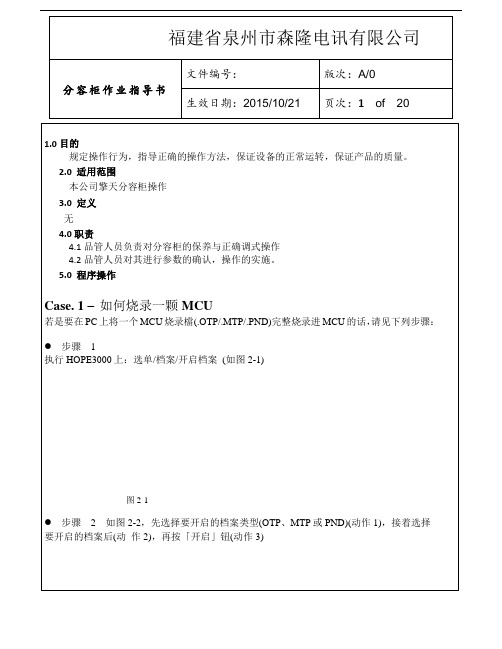
图2-2步骤3接着下载所开启的档案到烧录器上(选单\档案\下载),如下图2-3图2-3如果使用的是e-WriterPro的话,需再选择烧录的包装(如下图2-4)图2-4步骤4下载完毕后,若至此动作都成功的话,下方讯息窗口会显视「动作完全且成功」(如图2-5)。
接着便可开始烧录,依序按图2-4红框内「查空」、「烧录」、「校验」、「锁IC」(若要锁IC时)等按钮以便完成烧录,另外若是Flash MCU的话可按「擦除」将MCU里所有数据清除若有其它接口上细节问题,请见第3章「HOPE3000主功能介绍」;若是烧录过程有任何错误产生,请查询附录A「系统及错误讯息」以得到进一步的说明Case. 2 –如何自动烧录Case. 1是实现在PC上烧录,但都需要使用者按下「查空」、「烧录」、「校验」等钮才能完成烧录,这里介绍一种只要在HOPE3000上设定一次,之后只要按一次「自动烧录」钮即可完成上述烧录动作,适合在PC上做大量烧录使用。
操作方式见下列步骤:● 步骤1 ~ 3步骤同Case. 1的步骤1~3● 步骤4按下下图2-6红框内的「智能烧录」钮。
之后出现的智能烧录功能接口如图2-7● 步骤5在智能烧录功能接口中(图2-7),选择欲执行的烧录动作(重复图中动作1、2),再将设定下载烧录器上(动作3)图2-6步骤6若下载成功,上图2-7右下角的「自动烧录」按钮会致能。
接着按下该钮便会执行所选的烧录动作(每按一次执行一次)若有其它接口上细节问题,请见第3章「HOPE3000主功能介绍」或第4章「HOPE3000智能烧录功能介绍」;若是烧录过程有任何错误产生,请查询附录A「系统及错误讯息」以得到进一步的说明Case. 3 –如何只烧录部份IC有些应用可能会有多次烧写IC的需求,即每次只烧部份的数据,以下步骤即介绍如何烧录部份数据●步骤 1 ~ 4同Case. 2的●步骤5接着设定烧录范围,如下图2-8。
首先从「所有烧录动作」列中选取「烧录」(动作1),接着按下「---->」按钮(动作2),这时「欲执行的烧录动作」列中就出现「烧录」,按下去之后(动作3),底下「动作设定」区即会致能。
PULSAtron Series E Plus说明书

The PULSAtron Series E Plus offers manual control over stroke length and stroke rate as standard with the option to choose between 4-20mA and external pace inputs for automatic control.Twenty distinct models are available, having pressure capabilities to 300 PSIG (21 BAR) @ 3 GPD (0.5 lph), and flowcapacities to 600 GPD (94.6 lph) @ 30 PSIG (2 BAR), with a turndown ratio of 100:1. Metering performance is reproducible to within ± 2% of maximum capacity.Please refer to the reverse side for Series E PLUS specifications.FEATURES•Automatic Control, available with 4-20mADC direct orexternal pacing, with stop function.• Manual Control by on-line adjustable stroke rate and stroke length.• Auto-Off Manual switch.• Highly Reliable timing circuit.• Circuit Protection against voltage and current upsets.• Panel Mounted Fuse.• Solenoid Protection by thermal overload with auto-reset.• Water Resistant, for outdoor and indoor applications.• Indicator Lights, panel mounted.• Guided Ball Check Valve Systems, to reduce back flow and enhance outstanding priming characteristics.• Safe & Easy Priming with durable leak-free bleed valve assembly (standard)PULSAtron Series E PlusCONTROLSManual Stroke Rate • Turn-Down Ratio 10:1Manual Stroke Length • Turn-Down Ratio 10:14-20mADC Direct or External Pacing with Stop • Automatic ControlBENEFITS• Reliable metering performance.• Rated “hot” for continuous duty. • High viscosity capability. • Leak-free, sealless, liquid end.Punta Gorda, FL 33982Tel: (941) 575-3800Fax: (941) 575-4085An ISO Certified CompanyNOTE: Inches x 2.54 = cm /* the LPH8 is designed without a bleed valve available.SPECIFICATIONSEMP021 A22DIMENSIONSENGINEERING DATAImportant: Material Code - GFPPL=Glass-filled Polypropylene, PVC=Polyvinyl Chloride, PE=Polyethylene, PVDF=Polyvinylidene Fluoride, CSPE=Generic formulation of Hypalon, a registered trademark of E.I. DuPont Company. Viton is a registered trademark of E.I. DuPontCompany. PVC wetted end recommended for sodium hypochlorite。
E-prime操作教程
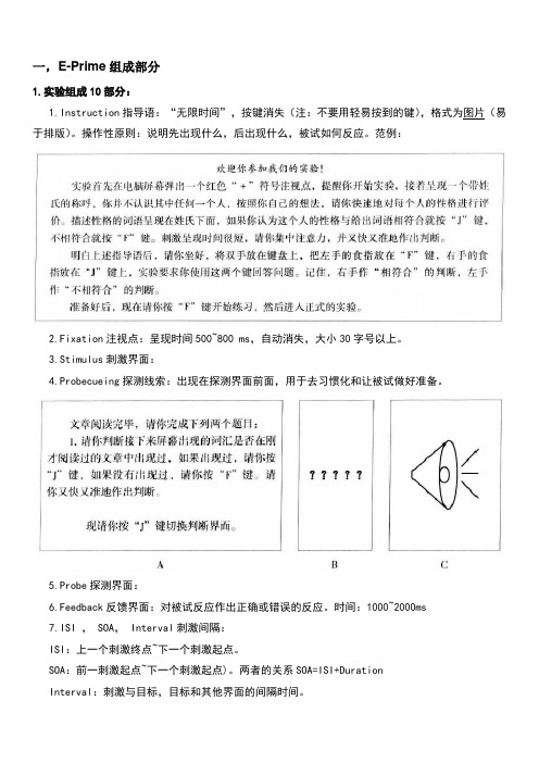
一,E-Prime组成部分1.实验组成10部分:1.Instruction指导语:“无限时间”,按键消失(注:不要用轻易按到的键),格式为图片(易于排版)。
操作性原则:说明先出现什么,后出现什么,被试如何反应。
范例:2.Fixation注视点:呈现时间500~800 ms,自动消失,大小30字号以上。
3.Stimulus刺激界面:4.Probecueing探测线索:出现在探测界面前面,用于去习惯化和让被试做好准备。
5.Probe探测界面:6.Feedback反馈界面:对被试反应作出正确或错误的反应。
时间:1000~2000ms7.ISI , SOA, Interval刺激间隔:ISI:上一个刺激终点~下一个刺激起点。
SOA:前一刺激起点~下一个刺激起点)。
两者的关系SOA=ISI+DurationInterval:刺激与目标,目标和其他界面的间隔时间。
8.Buffer Interval 实验缓冲:500~1200ms。
被试作反应后推迟下一个Trial的呈现。
反馈界面也起到缓冲的效果。
9.Mask 掩蔽界面:400~1000ms,常用于启动效应实验和记忆实验。
在记忆实验中,消除刺激的感觉记忆。
10.Exp End 结语界面:1000~1500ms,如,“实验完毕,谢谢您的参与!”2.实验程序控制5要素Duration呈现时间:固定时间,变化时间(设置变量或数组),无限时间(“-1”,“infinite”) Mode呈现方式(=消失方式):自动(不需要设置),按键(无限时间+设置按键在刺激界面),反应(无限时间+反应键在探测界面),自动+反应(固定时间+反应键)Format呈现格式:刺激物属性:字符(字体,大小,前景颜色?,背景颜色,下划线),图片(尺寸大小,文件大小,亮度,色调?,饱和度?,灰度?,对比度);位置;边框(大小,颜色)Response反应方式:键盘反应(字母,数字,功能键);语音反应;外接反应键;脚踏板反应Data logging数据收集:反应时Response Time ;RT ,正误Accuracy;ACC,反应Response;RESP,实验流程示意图3.实验过程Procedure:Session Procedure全过程;CEP Core Experimental Procedure(运行一次是一次Trial,一个Block=指导语+CEP+结束语)4.实验设计的4模式:Paralleling并联模式:(图B)完成CEP1再完成CEP2。
SmartAVI EZWALL-PLUS 2X2 用户手册说明书
EZWALL-PLUS 2X2User ManualMulti-Format Video Wall Controller2x2 HD Video Wall Controller HDMI, DVI, and VGA Input Integrated USBMedia PlayerWHAT’S IN THE BOX? INTRODUCTIONFEATURES APPLICATIONSTECHNICAL SPECIFICATIONS HARDWARE INSTALLATION FRONT PANEL CONTROLIR REMOTE CONTROL CONTROL VIA ETHERNET/IP LIMITED WARRANTY STATEMENT TABLE OF CONTENTS WHAT’S IN THE BOX 2 3 3 3 47 5 9 11 14The EZWALL-PLUS 2X2 offers top-notch HD-HDMI output for five different types of signal inputs. Create striking 2x2 wall displays easily with simple signal switching and flexible connectivity. The EZWALL-PLUS 2X2 even features a fully-integrated USB media player.The EZWALL-PLUS 2X2 is capable of expanding any supported video input to four-large screens at 1080p, thus showcasing its stunning picture quality. In this guide, you will learn how to install and optimize your experience with the EZWALL-PLUS 2X2 using basic steps. These steps will include setting up the hardware, activating and connecting your system, and offer helpful tips on how to best use the EZWall-PLUS 2X2’s excellent selection of picture modes to enhance your video wall.• Corporate or Educational Presentations • Airport Installations • Wall Displays • Digital Signage • Dealer Rooms • Control Rooms • Shopping Centers • Security • Point-of-Sale• Entertainment Venues • Corporate Lobbies •RestaurantsINTRODUCTION• Four screen (2x2) multi-layout, multi-format video wall controller • Outputs: (4) HDMI• Inputs: (1) HDMI, (1) VGA, (1) DVI• Integrated USB media player for digital video, imagery, and audio • Internal EDID learning• 1080p (1920 x 1080 @ 60 Hz) Full HD resolution output • No additional hardware or software required • Supports control via Front Panel Buttons • Supports control via IR Remote control • Supports control via TCP/IP •HDCP and HDMI 1.4 compliantFEATURESAPPLICATIONSTECHNICAL SPECIFICATIONS*PLEASE NOTE: EZ-WALL-PLUS 2X2 only supports the primary formats listed above. Any unlisted formats are not compatible with EZWall-PLUS 2X2.For the safety of your equipment, please read the safety instructions carefully before using or installing this device.• This equipment uses 12V/3A external power supply; power supply supports 100-240V AC voltage input, only use the provided power supply.• Please make sure to power off when you connect cables or carry the equipment.• Do not bundle the cables, rather separate the power cables and signal cables to prevent interference.• Keep cooling vent openings free of any obstructions to allow proper facilitation of cool air to the device • All maintenance work should be done by professional maintenance personnel.• Position EZWALL-PLUS 2X2 conveniently and keep it unplugged.• Connect the HDMI output cables between the EZWALL-PLUS 2X2 and your video wall screens.• Connect any input to their corresponding signal source input connector (Blu-ray player, computer, etc). • Optionally connect the IR-EYE (receiver) to the IR input jack on the EZWALL-PLUS 2X2 • Optionally connect an audio source to the audio input jack on the EZWALL-PLUS 2X2.• Optionally connect an Ethernet cable for additional control over your LAN or the internet (TCP/IP) • Optionally connect USB storage devices• Optionally connect speakers. (You can use sound via HDMI instead if your systems support this.) • Turn on the EZWALL-PLUS 2X2 and wait a few seconds for the unit to initialize.HDMI Output and TV ConnectionHDMI1 connect to LCD1(Display 1);HDMI2 connect to LCD2(Display 2);HDMI3 connect to LCD3(Display 3);HDMI4 connect to LCD4(Display 4).The following diagram shows the inputs available in on the back panel:HARDWARE INSTALLATIONDevice Pictures and Dimensions9.5” (241 mm) W x 2” (51 mm) H x 8” (183 mm) D (without Tripod);9.5” (241 mm) W x 2” (51 mm) H x 8” (203 mm) D (with Tripod);Figure 6-1: System topology diagram9.5” (241 mm)2” (51 m m )HARDWARE INSTALLATION (Continued)LANUSB12HDMI 3HDMI OUTPUT4IN OUTAUDIORS232VGADVI 12VIR STEREO SPEAKERAUDIO OUTPUTPC AUDIOVGADVIUSBHDMIRS232VGA HDMI USB DISKPCFigure 7-1FRONT PANEL CONTROLWALL MODEAn Image can be displayed across four HD screens 2X2.To switch between listed sources, press: 1. VGA2. HDMI/DVI3. USBTo switch to Video Wall mode, press the WALL button. To switch to Clone mode, press the CLONE button. Pressing the LOCK button will disable the other buttons.FRONT PANEL CONTROL (Continued)CLONE MODEThe image can be displayed on each display individually.Figure 8-1Figure 8-2Figure 8-3WALL MODE - VIDEO FLIPMany HDTV displays have a bezel that is wider on the bottom than it is on the top and sides. The Wall mode video flip feature fixes this by allowing you to flip the top two displays in your video wall by 180 degrees so the wide edges are no the outside of the video wall.An Image can be displayed across four HD screens 2X2.S m a r t A V ISmartAVISmartAVISmartAVI S m a r t A V IS m a r t A V IS m a r t A V ISmartAVISmartAVI SmartAVISmartAVISmartAVIFigure 9-1IR REMOTE CONTROLNote that when not using all four displays the unused displays will be a clone of output #1.Figure 10-1: 1X2 Mode (F1 Button)Figure 10-2: 2X1 Mode (F2 Button)IR REMOTE CONTROL (Continued)CONTROL VIA ETHERNET/IPEZWALL-PLUS 2X2 TCP/IP control is a feature that allows mode switching and other configurations to be con -trolled remotely via HTTP . Manage your EZWALL-PLUS 2X2 with ease from anywhere in the world. First, find the IP address for the EZ-Wall-Pro. Finder.exe (Smart IP-Finder) is conveniently available on our website (please visit /helpful-links.html for this and our full list of compatible third-party software). Download the IP address finder software for your device. The EZWALL-PLUS 2X2 and its IP address should appear in the display as shown in the figure 10-1.Enter the IP address into the web browser of your choice. When asked for the username and password, enter the default credentials, admin/admin. You can change the User ID and password by clicking the configurations tab. You should then see the EZWALL-PLUS 2X2 Home/Welcome page as shown in figure 10-2.Figure 11-1Figure 11-2CONTROL VIA ETHERNET/IP (Continued)Click the CONFIGURATION tab in the top toolbar to configure your network settings.You can easily switch to WALL MODE or CLONE MODE based on your set up.Figure 12-1Figure 12-2CONTROL VIA ETHERNET/IP (Continued)Figure 13-1USB functionThe EZWALL-Plus can support video, audio, picture, and text files from a USB Drive.Video includes many different formats such as MP4, AVI, MPEG, WMV, RMVB with resolutions up to 1080P.LIMITED WARRANTY STATEMENTA. Extent of limited warrantySmartAVI Technologies, Inc. warrants to the end-user customers that the SmartAVI product specified above will be free from defects in materials and workmanship for the duration of 1 year, which duration begins on the date of purchase by the customer. The customer is responsible for maintaining proof of date of purchase. SmartAVI’s limited warranty covers only those defects which arise as a result of normal use of the product, and do not apply to any:a. Improper or inadequate maintenance or modificationsb. Operations outside product specificationsc. Mechanical abuse and exposure to severe conditionsIf SmartAVI receives (during applicable warranty period) a notice of defect, SmartAVI will at its discretion replace or repair the defective product. If Smart-AVI is unable to replace or repair the defective product covered by the SmartAVI warranty within a reasonable period of time, SmartAVI shall refund the cost of the product.SmartAVI will have no obligation to repair, replace or refund unit until customer returns the defective product to SmartAVI.Any replacement product could be new or like new, provided that it has functionality at least equal to that of the product being replaced.Smart-AVI limited warranty is valid in any country where the covered product is distributed by SmartAVI.B. Limitations of warrantyTo the extent allowed by local law, neither SmartAVI nor its third party suppliers make any other warranty or condition of any kind whether expressed or implied with respect to the SmartAVI product, and specifically disclaim implied warranties or conditions of merchantability, satisfactory quality, and fitness for a particular purpose.C. Limitations of liabilityTo the extent allowed by local law, the remedies provided in this warranty statement are the customers sole and exclusive remedies.To the extent allowed by local law, except for the obligations specifically set forth in this warranty statement, in no event will SmartAVI or its third party suppliers be liable for direct, indirect, special, incidental, or consequential damages whether based on contract, tort or any other legal theory and whether advised of the possibility of such damages.D. Local lawTo the extent that this warranty statement is inconsistent with local law, this warranty statement shall be considered modified to be consistent with such law.Designed and Manufactured in the USANOTICEThe information contained in this document is subject to change without notice. Smart-AVI makes no warranty of any kind with regard to this material, including but not limited to, implied warranties of merchantability and fitness for particular purpose. Smart-AVI will not be liable for errors contained herein or for incidental or consequential damages in connection with the furnishing, performance or use of this material. No part of this document may be photocopied, reproduced, or translated into another language without prior written consent from Smart-AVI Technologies, Inc. 20180720800.AVI.2131Tel: (818) 503-6200 | Fax: (818) 503-6208 2455 W Cheyenne Ave, Suite 112, Las Vegas, NV 。
- 1、下载文档前请自行甄别文档内容的完整性,平台不提供额外的编辑、内容补充、找答案等附加服务。
- 2、"仅部分预览"的文档,不可在线预览部分如存在完整性等问题,可反馈申请退款(可完整预览的文档不适用该条件!)。
- 3、如文档侵犯您的权益,请联系客服反馈,我们会尽快为您处理(人工客服工作时间:9:00-18:30)。
图2-2步骤3接着下载所开启的档案到烧录器上(选单\档案\下载),如下图2-3图2-3如果使用的是e-WriterPro的话,需再选择烧录的包装(如下图2-4)图2-4步骤4下载完毕后,若至此动作都成功的话,下方讯息窗口会显视「动作完全且成功」(如图2-5)。
接着便可开始烧录,依序按图2-4红框内「查空」、「烧录」、「校验」、「锁IC」(若要锁IC时)等按钮以便完成烧录,另外若是Flash MCU的话可按「擦除」将MCU里所有数据清除若有其它接口上细节问题,请见第3章「HOPE3000主功能介绍」;若是烧录过程有任何错误产生,请查询附录A「系统及错误讯息」以得到进一步的说明Case. 2 –如何自动烧录Case. 1是实现在PC上烧录,但都需要使用者按下「查空」、「烧录」、「校验」等钮才能完成烧录,这里介绍一种只要在HOPE3000上设定一次,之后只要按一次「自动烧录」钮即可完成上述烧录动作,适合在PC上做大量烧录使用。
操作方式见下列步骤:● 步骤1 ~ 3步骤同Case. 1的步骤1~3● 步骤4按下下图2-6红框内的「智能烧录」钮。
之后出现的智能烧录功能接口如图2-7● 步骤5在智能烧录功能接口中(图2-7),选择欲执行的烧录动作(重复图中动作1、2),再将设定下载烧录器上(动作3)图2-6步骤6若下载成功,上图2-7右下角的「自动烧录」按钮会致能。
接着按下该钮便会执行所选的烧录动作(每按一次执行一次)若有其它接口上细节问题,请见第3章「HOPE3000主功能介绍」或第4章「HOPE3000智能烧录功能介绍」;若是烧录过程有任何错误产生,请查询附录A「系统及错误讯息」以得到进一步的说明Case. 3 –如何只烧录部份IC有些应用可能会有多次烧写IC的需求,即每次只烧部份的数据,以下步骤即介绍如何烧录部份数据●步骤 1 ~ 4同Case. 2的●步骤5接着设定烧录范围,如下图2-8。
首先从「所有烧录动作」列中选取「烧录」(动作1),接着按下「---->」按钮(动作2),这时「欲执行的烧录动作」列中就出现「烧录」,按下去之后(动作3),底下「动作设定」区即会致能。
接着设定烧录部份的Code(动作4),再按下「选择」钮(动作5)以便出现如图2-9中的窗口作进一步的范围设定图2-821● 步骤6在下图2-9中的模式选择「图标」(动作1)后窗口左侧即出现可供选择的ROM 区块。
接着按下「增加选择」钮(动作2)后,指定要烧录的区块(动作3),最后按「确定」(动作4)储存设定并离开设定窗口图2-9步骤7重复步骤5~6以便加入「擦除」、「查空」、「校验」或「锁IC」等烧录动作,如图2-10。
接着将设定下载到烧录器上(动作1),若成功,「自动烧录」按钮会致能,最后按下「自动烧录」按钮(动作2)即会执行指定的动作,之后每按一次「自动烧录」按钮即完成一次烧录若有其它接口上细节问题,请见第3章「HOPE3000主功能介绍」或第4章「HOPE3000智能烧录功能介绍」;若是烧录过程有任何错误产生,请查询附录A「系统及错误讯息」以得到进一步的说明图2-10Case. 4 –如何烧录序号或其它自订数据如果要将序号或其它数据烧入Program ROM,则需要使用智能烧录里的使用者自订数据功能,以下步骤即介绍如何使用这个功能:●步骤1~4同Case. 2的1~4●步骤5如图2-11动作1~3,将「使用者自订数据」加入「欲执行的烧录动作」列后,执行「动作设定」区中的「设定」功能(动作4)后,出现如图2-12的使用者自订数据设定窗口● 步骤6设定自订数据细节。
图2-12展示了「在IC中Program ROM的地址100H处烧录一笔数据」的设定,数据是以N+1数学式子产生,N的初值为22(即所烧第一颗IC为22,第二颗为23,…)。
完成动作1~3等设定后,按「确定」以便储存设定并离开此窗口。
※图2-12中的其它设定细节请见第四章「HOPE3000智能烧录功能介绍」的「使用者自订数据设定窗口」一节图2-12● 步骤7接着将设定下载到烧录器上,如图2-13的动作1。
下载成功后,可以看见红框2中出现第一笔要烧的数据;接着按下「自动烧录」钮(动作3)以进行数据的烧录,每按一次即烧录一笔,而每次执行完自动烧录后,红框2的地方会显示下一笔要烧的资料图2-13另外要提的是在Case 3中设定部份烧录时也可以同时设定使用者自订资料。
若有其它接口上细节问题,请见第3章「HOPE3000主功能介绍」或第4章「HOPE3000智能烧录功能介绍」;若是烧录过程有任何错误产生,请查询附录A「系统及错误讯息」以得到进一步的说明Case. 5 –如何离线烧录若是需要离线烧录(即不需接PC即可操作烧录器)时,需先连上PC将烧录档及烧录动作设定下载至烧录器,再按下烧录器上的烧录键以进行烧录,详细步骤请见下列:● 步骤1~5下载烧录档案及烧录动作设定至烧录器。
同Case2的步骤1~5● 步骤6接着关闭HOPE3000程序,移除烧录器上与PC连接的USB接头● 步骤7将电源接上烧录器。
此时烧录器会检查在步骤1~5下载的数据是否正确,如果正确,烧录器会停在待机状态(Ready,即黄色LED灯会亮起);否则为错误状态(Fail,即红色LED 灯会亮起),需重新下载数据到烧录器(即重做步骤1~5)※注意:黄色LED灯(Ready灯)亮起才可继续下一步● 步骤8放上IC(该型号需与在步骤1~5中所下载烧录档的MCU型号一样),按下烧录器上的烧录命令键(即图1-13~1-15的烧录键)以进行烧录● 步骤9检查LED指示灯以确认烧录是否成功(绿色/蓝色LED灯慢闪且其它二个LED灯暗灭)注:e-WriterPro是蓝灯,e-Writer及e-Writer plus是绿灯若有其它接口上细节问题,请见第3章「HOPE3000主功能介绍」或第4章「HOPE3000智能烧录功能介绍」;若是烧录过程有任何错误产生,请见查询附录A「系统及错误讯息」以得到进一步的说明;对于烧录器上的灯号有问题者请见附录B「烧录器灯号及状态」Case. 6 –如何读取IC上的数据(不需开启烧录檔)一般要读取IC上的数据之前,要先开档将该IC的烧录档下载至烧录器或烧录器上已有该IC 的资料,这里介绍一种在没有该IC的烧录檔或烧录器上纪录的数据并非属于该IC时,仍可直接透过HOPE3000读取IC上的数据,详细步骤如下:如图2-14图2-14● 步骤2接着出现选择IC的对话盒,从「从所有IC」中选择所要读取的IC(如图2-15)后,按「确定」钮离开图2-15如果使用的是e-WriterPro的话,需再选择烧录的包装(如下图2-16)图2-16● 步骤3之后HOPE3000会下载所选IC型号的Driver到烧录器上,如果成功的话,可以见到下图2-17的烧录动作按钮有部份致能,这时就可直接按「读取」钮直接读取IC的数据,读取之后再执行「选单/档案/上载」即可将IC上的数据显示在HOPE3000程序上图2-17若有其它接口上细节问题,请见第三章「HOPE3000主功能介绍」;若是烧录过程有任何错误产生,请查询附录A「系统及错误讯息」以得到进一步的说明Case. 7 –如何以下命令的方式执行烧录动作HOPE3000支持命令模式,即DOS Command Mode功能,启动方式如下:● 步骤1关闭HOPE3000程序,开启Microsoft Windows下的「命令提示字符」程序※注意:HOPE3000程序与DOS Command Mode程序不能同时执行,否则会影响烧录结果3步骤所指定的目录),再输入DOS Command Mode的执行档名:WCMD.EXE (如图2-18)图2-18● 步骤3这时会出现DOS Command Mode的参数及简易的使用说明(如图2-19红框处),接着按说明输入命令即可其它DOS Command Mode的详细使用内容,请见「第五章HOPE3000 - Dos Command Mode 介绍」;若是烧录过程有任何错误产生,请查询附录A「系统及错误讯息」以得到进一步的说明Case. 8 –如何连上PC更新烧录器韧体(Firmware)e-Writer plus(注)支持连PC更新韧体功能,以下介绍如何将它的韧体版本更新至HOPE3000内含的版本(更新前请确定HOPE3000是最新的版本)● 步骤1执行「选单/工具/F/W更新」以启动韧体更新窗口(如图2-20中上方红框)。
注意下图右下角方框处为更新前的韧体版本图2-20● 步骤2如下图2-21便是韧体更新窗口,请按下「开始」钮以开始进行韧体的更新。
图2-21● 步骤3若此时已连上烧录器,则韧体开始更新图2-22图2-23● 步骤4若更新成功,则韧体更新窗口会显示「F/W已更新完成」(如图2-24),接着HOPE3000会自动重置烧录器。
待联机成功后,更新后的韧体版本会显示在下图右下角若有其它接口上细节问题,请见第三章「HOPE3000主功能介绍」;若是韧体更新过程有任何错误产生,请查询附录A「系统及错误讯息」以得到进一步的说明Case. 9 –如何注册及启用烧录器拿到一台新的e-WriterPro时,需要做烧录器启用的动作,否则是无法做任何烧录动作的。
要启用烧录器需取得烧录器的注册码,而注册码则透过烧录器注册流程取得,以下是注册及启用烧录器的步骤● 步骤1执行「选单/工具/启用烧录器」以启动「启用烧录器」窗口。
注意当烧录器未启用时,下图2-25右下角会出现这台烧录器未启用的讯息图2-25● 步骤2下图2-26为烧录器启用窗口,图中方框为侦测到的烧录器ID,请按下方「立即注册!」按钮来为这台烧录器注册若已取得注册码者,可直接跳到步骤6来启用烧录器● 步骤3注册窗体画面,图中2-27三项是必填项目,其中e-Mail请填写您正在使用的信箱地址,用以收取注册码信件用(请勿填非您本人使用之信箱,以免注册码被他人知悉)。
32其它字段也请填妥以方便我们为您做售后服务,相关使用者信息HOLTEK会严加保密。
输入完成后,请按「注册」钮。
图2-27● 步骤4当注册成功时,即会出现下图2-28之对话窗口,此时便可直接去图2-27中指定的信箱收信。
若注册失败,请再试步骤3;若一直无法注册成功,请联络HOLTEK以解决此问题图2-28● 步骤5若信箱指定正确,可在您的信箱中见到一封由HOLTEK发出,主旨为「e-Writer Pro RegistryKey」信件图打开信件,则可以见到下图2-30中红框的注册码(图中为信件片段)图2-30步骤6此时HOPE3000会在启用画面,只要输入注册码(图2-31红框1),再按「启用」钮即可进行烧录器启用图2-31步骤7若启用成功,则会出现图2-32的成功讯息,之后便可使用烧录器做烧录。
