螺丝标准二
常用螺丝制造标准
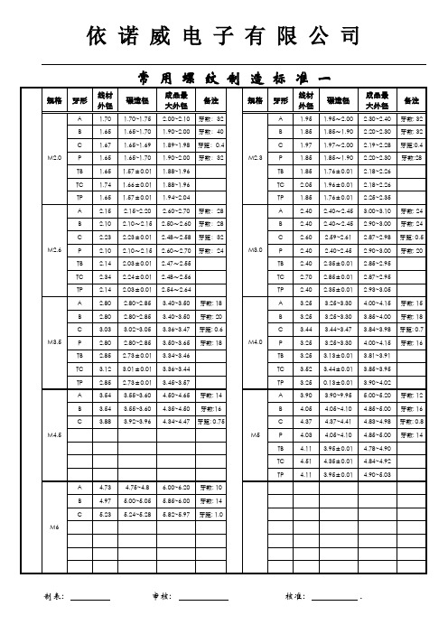
3.30 3.35 3.56 3.35 3.40 3.65 3.40 2.55
3.30~3.35 3.35~3.40 3.56~3.59 3.35~3.40 3.31~3.35 3.49~3.51 3.31~3.35 2.55~2.60
4.11~4.26 4.08~4.21 3.99~4.14 4.09~4.21 4.09~4.21 3.94~4.01 4.09~4.21 3.17~3.27
碾造径
1.95~2.00 1.85~1.90 1.97~2.00 1.85~1.90 1.76±0.01 1.96±0.01 1.76±0.01 2.40~2.45 2.40~2.45 2.59±0.01 2.40~2.45 2.35±0.01 2.85±0.01 2.35±0.01 3.25~3.30 3.25~3.30 3.42~3.45 3.25~3.30 3.13±0.01 3.44±0.01 0.13±0.01 3.90~9.95 4.05~4.10 4.38~4.43 4.05~4.10 3.95±0.01 4.35±0.01 3.95±0.01
成品最 大外径
2.00~2.10 1.90~2.00 1.89~1.98 1.90~2.00 1.88~1.96 1.88~1.96 1.94~2.04 2.60~2.70 2.50~2.60 2.48~2.58 2.60~2.70 2.47~2.55 2.48~2.56 2.54~2.64 3.40~3.50 3.40~3.50 3.36~3.47 3.50~3.65 3.34~3.46 3.36~3.44 3.45~3.57 4.50~4.65 4.35~4.50 4.34~4.47
备注
牙数:32 牙数:40 牙距:0.4 牙数:32
普通螺栓的标准及其规格表
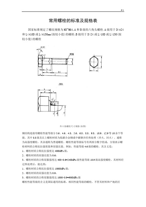
常用螺栓的标准及规格表国家标准规定了螺纹规格为M3~M64,A和B级的六角头螺栓.A级用于D<=24和L<=10D或L<=150mm(按较小值)的螺栓;B级用于D>24或L>10D或L>150(按较小值)的螺栓外六角螺栓尺寸规格(如图)钢结构连接用螺栓性能等级分3.6、4.6、4.8、5.6、6.8、8.8、9.8、10.9、12.9等10余个等级,其中8.8级及以上螺栓材质为低碳合金钢或中碳钢并经热处理(淬火、回火),通称为高强度螺栓,其余通称为普通螺栓。
螺栓性能等级标号有两部分数字组成,分别表示螺栓材料的公称抗拉强度值和屈强比值。
例如,性能等级4.6级的螺栓,其含义是:1、螺栓材质公称抗拉强度达400MPa级;2、螺栓材质的屈强比值为0.6;3、螺栓材质的公称屈服强度达400×0.6=240MPa级性能等级10.9级高强度螺栓,其材料经过热处理后,能达到:1、螺栓材质公称抗拉强度达1000MPa级;2、螺栓材质的屈强比值为0.9;3、螺栓材质的公称屈服强度达1000×0.9=900MPa级螺栓性能等级的含义是国际通用的标准,相同性能等级的螺栓,不管其材料和产地的区别,其性能是相同的,设计上只选用性能等级即可。
常用螺丝规格表强度等级所谓8.8级和10.9级是指螺栓的抗剪切应力等级为8.8GPa和10.9Gpa8.8 公称抗拉强度800N/MM2 公称屈服强度640N/MM2 一般的螺栓是用"X.Y"表示强度的,X*100=此螺栓的抗拉强度,X*100*(Y/10)=此螺栓的屈服强度(因为按标识规定:屈服强度/抗拉强度=Y/10)===============如4.8级则此螺栓的抗拉强度为:400MPa屈服强度为:400*8/10=320MPa=================另:不锈钢螺栓通常标为A4-70,A2-70的样子,意义另有解释度量当今世界上长度计量单位主要有两种,一种为公制,计量单位为米(m)、厘米(cm)、毫米(mm)等,在欧州、我国及日本等东南亚地区使用较多,另一种为英制,计量单位主要为英寸(inch),相当于我国旧制的市寸,在美国、英国等欧美国家使用较多。
常用螺栓螺距表

螺丝规格与螺距螺纹规格牙距M2 标准 0.40 细牙 0.25M2.5 标准 0.45 细牙 0.35M2.6 标准 0.45 细牙 0.35M3 标准 0.50 细牙 0.35M3.5 标准 0.60 细牙 0.35M4 标准 0.70 细牙 0.50M5 标准 0.80 细牙 0.50M6 标准 1.00 细牙 0.75M8 标准 1.25 细牙1 1.00 细牙2 0.75M10 标准 1.50 细牙1 1.25 细牙2 1.00 细牙3 0.75 M12 标准 1.75 细牙1 1.50 细牙2 1.25 细牙3 1.00 M14 标准 2.00 细牙1 1.50 细牙2 1.00M16 标准 2.00 细牙1 1.50 细牙2 1.00M18 标准 2.50 细牙1 2.00 细牙2 1.50 细牙3 1.00钢结构连接用螺栓性能等级分3.6、4.6、4.8、5.6、6.8、8.8、9.8、10.9、12.9等10余个等级,其中8.8级及以上螺栓材质为低碳合金钢或中碳钢并经热处理(淬火、回火),通称为高强度螺栓,其余通称为普通螺栓。
螺栓性能等级标号有两部分数字组成,分别表示螺栓材料的公称抗拉强度值和屈强比值。
例如:性能等级4.6级的螺栓,其含义是:1、螺栓材质公称抗拉强度达400MPa级;2、螺栓材质的屈强比值为0.6;3、螺栓材质的公称屈服强度达400×0.6=240MPa级性能等级10.9级高强度螺栓,其材料经过热处理后,能达到: 1、螺栓材质公称抗拉强度达1000MPa级; 2、螺栓材质的屈强比值为0.9;3、螺栓材质的公称屈服强度达1000×0.9=900MPa级螺栓性能等级的含义是国际通用的标准,相同性能等级的螺栓,不管其材料和产地的区别,其性能是相同的,设计上只选用性能等级即可。
强度等级所谓8.8级和10.9级是指螺栓的抗剪切应力等级为8.8GPa 和10.9GPa 8.8 公称抗拉强度800N/MM2 公称屈服强度640N/MM2 一般的螺栓是用"X.Y"表示强度的,X*100=此螺栓的抗拉强度,X*100*(Y/10)=此螺栓的屈服强度(因为按标识规定:屈服强度/抗拉强度=Y/10)如4.8级则此螺栓的抗拉强度为:400MPa;屈服强度为:400*8/10=320MPa。
philip2螺丝头的标准

Philip2螺丝头,通常是指Phillips #2螺丝头,是Phillips螺丝头的一种常见规格。
Phillips螺丝头是一种十字形的槽口设计,由亨利·菲利普斯在20世纪30年代发明,用于改进传统平头或十字槽螺丝的使用效率和可靠性。
Phillips #2螺丝头的标准特征包括:
1. 槽口形状:十字形,有两个对角线槽口,槽口角度约为45度。
2. 槽口尺寸:相比于Phillips #1和#3,#2螺丝头的槽口深度和宽度居中。
它的尺寸设计旨在提供良好的扭矩传递,既不会过于紧而导致螺丝刀滑出,也不会过于松导致扭力不足。
3. 使用范围:Phillips #2螺丝头是最常用的规格之一,广泛应用于各种家用电器、家具、电子设备和其他工业产品中。
在使用Phillips #2螺丝刀进行操作时,应确保螺丝刀与螺丝头的槽口紧密配合,以防止滑牙或损坏螺丝头。
此外,尽管Phillips螺丝头设计用于减少“跳牙”现象(即螺丝刀在高扭矩下从槽口中弹出),但在高负荷应用中仍可能遇到这个问题,因此在某些专业或重型应用中,可能会选择其他类型的螺丝头设计,如Pozidriv 或Torx 等。
螺丝常见标准
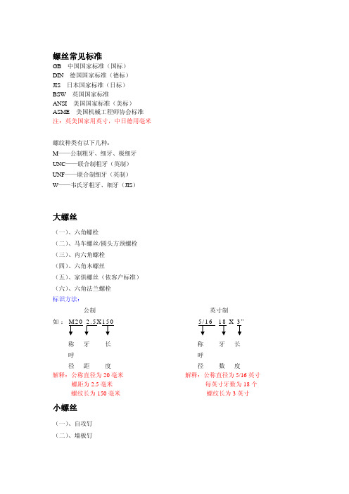
15.500 19.000 18.500 18.000 17.500 21.000 20.500 20.000 19.500 23.000 22.500 22.000 21.000 24.000 26.500 29.500 32.000 35.000 37.500 40.500 43.000
14.0 1.00 1.25 1.50 2.00
16.0 1.00 1.50 2.00
17.0 1.00 1.50
18.0 1.00 1.50 2.00
5.500 5.250 5.000 6.500 6.250 6.000 7.500 7.250 7.000
8.500 8.250 8.000 7.750 9.500 9.250 9.000 8.750 8.500 0.355 10.000 9.500 11.000 10.750 10.500 10.250 13.000 12.750 12.500 12.000 15.000 14.500 14.000 16.000 15.500 17.000 16.500 16.000
7
12
1.3750
1-3/8
6
12
1.5000
1-1/2
6
12
1.6250
1-5/8
1.7500
1-3/4
5
2.0000
2
4.5
2.2500
2-1/4
4.5
2.5000
2-1/2
4
2.7500
2-3/4
4
3.0000
3
4
3.2500
3-1/4
4
3.5000
3-1/2
4
3.7500
3-3/4
常用螺栓的标准及规格表
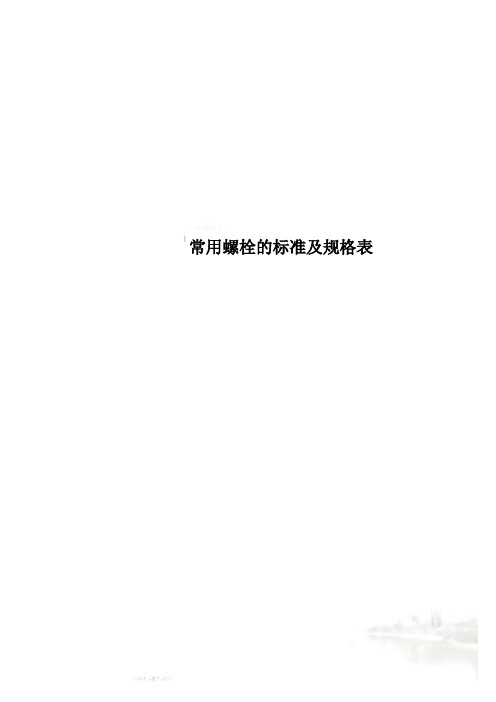
常用螺栓的标准及规格表常用螺栓的标准及规格表国家标准规定了螺纹规格为M3~M64,A和B级的六角头螺栓.A级用于D<=24和L<=10D或L<=150mm(按较小值)的螺栓;B级用于D>24或L>10D或L>150(按较小值)的螺栓外六角螺栓尺寸规格(如图)钢结构连接用螺栓性能等级分3.6、4.6、4.8、5.6、6.8、8.8、9.8、10.9、12.9等10余个等级,其中8.8级及以上螺栓材质为低碳合金钢或中碳钢并经热处理(淬火、回火),通称为高强度螺栓,其余通称为普通螺栓。
螺栓性能等级标号有两部分数字组成,分别表示螺栓材料的公称抗拉强度值和屈强比值。
例如,性能等级4.6级的螺栓,其含义是:1、螺栓材质公称抗拉强度达400MPa级;2、螺栓材质的屈强比值为0.6;3、螺栓材质的公称屈服强度达400×0.6=240MPa 级性能等级10.9级高强度螺栓,其材料经过热处理后,能达到:1、螺栓材质公称抗拉强度达1000MPa级;2、螺栓材质的屈强比值为0.9;3、螺栓材质的公称屈服强度达1000×0.9=900MPa级螺栓性能等级的含义是国际通用的标准,相同性能等级的螺栓,不管其材料和产地的区别,其性能是相同的,设计上只选用性能等级即可。
常用螺丝规格表类别规格牙距成品外径线径类别规格牙数(每英寸)成品外径线径最大最小±0.02mm 最大最小±0.02mm国标粗牙60° M1.4 0.30 1.38 1.34 1.16英制粗牙55°1/8 40 3.145 3.03 2.70 M1.7 0.35 1.68 1.61 1.42 5/32 32 3.945 3.795 3.38 M2.0 0.40 1.98 1.89 1.68 3/16 24 4.732 4.592 4.00 M2.3 0.40 2.28 2.19 1.98 1/4 20 6.32 6.165 5.45 M2.5 0.45 2.48 2.38 2.15 5/16 18 7.905 7.737 6.94 M3.0 0.50 2.98 2.88 2.60 3/8 16 9.49 9.312 8.40 M3.5 0.60 3.47 3.36 3.02 7/16 14 11.07 10.88 9.84 M4.0 0.70 3.98 3.83 3.40 1/2 12 12.66 12.46 11.22 M4.5 0.75 4.47 4.36 3.88 9/16 12 14.25 14.04 12.81 M5.0 0.80 4.98 4.83 4.30 5/8 11 15.83 15.61 14.27 M6.0 1.00 5.97 5.82 5.18美制粗牙60°4# 40 2.824 2.695 2.37 M7.0 1.00 6.97 6.82 6.18 5# 40 3.154 3.026 2.69 M8.0 1.25 7.96 7.79 7.02 6# 32 3.484 3.333 2.91 M9.0 1.25 8.96 8.79 8.01 8# 32 4.142 3.991 3.57 M10 1.50 9.96 9.77 8.84 10# 24 4.8 4.618 4.05 M11 1.50 10.97 10.73 9.84 12# 24 5.461 5.279 4.70 M12 1.75 11.95 11.76 10.7 1/4 20 6.322 6.117 5.45 M14 2.00 13.95 13.74 12.5 5/16 18 7.907 7.687 6.93 M16 2.00 15.95 15.74 14.5 3/8 16 9.491 9.254 8.40 M18 2.50 17.95 17.71 16.2 7/16 14 11.08 10.82 9.83 M20 2.50 19.95 19.71 18.2 1/2 13 12.66 12.39 11.32国标细牙M4.0 0.50 3.97 3.86 3.58 9/16 12 14.25 13.96 12.80 M4.5 0.50 4.47 4.36 4.07 5/8 11 15.83 15.53 14.26 M5.0 0.50 4.97 4.86 4.57 美制4# 48 2.877 2.713 2.44 M6.0 0.75 5.97 5.85 5.41 5# 44 3.157 3.036 2.7360° M7.0 0.75 6.97 6.85 6.41 粗牙60°6# 40 3.484 3.356 3.02 M8.0 1.00 7.97 7.83 7.24 8# 36 4.145 4.006 3.63 M9.0 1.00 8.97 8.83 8.24 10# 32 4.803 4.651 4.23 M10 1.00 9.97 9.82 9.23 12# 28 5.461 5.296 4.81 M10 1.25 9.96 9.81 9.07 1/4 28 6.324 6.16 5.68 M12 1.25 11.97 11.76 11.07 5/16 24 7.909 7.727 7.16 M12 1.50 11.96 11.79 10.89 3/8 24 9.497 9.315 8.74 M14 1.50 13.96 13.79 12.89 7/16 20 11.08 10.87 10.18 M16 1.50 15.96 15.79 14.89 1/2 20 12.67 12.46 11.76 M18 1.50 17.95 17.73 16.86 9/16 18 14.25 14.03 13.25 M20 1.50 19.95 19.65 18.85 5/8 18 15.83 15.62 14.83类别规格牙数或牙数成品外径线径类别规格牙数或牙数成品外径线径最大最小±0.02mm 最大最小±0.02mm国标7660° M3.0 1.2 3.0 2.85 2.38美制铁板A牙60°2# 32 2.23 2.13 1.78 M3.5 1.4 3.5 3.35 2.75 3# 28 2.56 2.46 2.08 M4.0 1.6 4.0 3.85 3.15 4# 24 2.89 2.79 2.28 M4.5 1.8 4.5 4.35 3.47 5# 20 3.30 3.20 2.60 M5.0 2 5.0 4.85 3.90 6# 18 3.58 3.45 2.78 M6.0 2.5 6.0 5.85 4.67 7# 16 4.01 3.86 3.10日制A 牙铁铁钉60° M2.0 32 2.10 2.00 1.70 8# 15 4.26 4.11 3.30 M2.3 32 2.40 2.30 1.95 9# 14 4.55 4.40 3.45 M2.6 28 2.70 2.60 2.10 10# 12 4.92 4.77 3.75 M3.0 24 3.10 3.00 2.42 12# 11 5.60 5.46 4.30 M3.5 18 3.65 3.50 2.83 14# 10 6.45 6.29 5.05 M4.0 16 4.15 4.00 3.25美制铁板AB牙60°2# 32 2.23 2.08 1.78 M4.5 14 4.65 4.50 3.60 3# 28 2.56 2.46 2.05 M5.0 12 5.20 5.00 4.00 4# 24 2.89 2.74 2.28 M6.0 10 6.20 6.00 4.85 5# 20 3.30 3.20 2.57 M8.0 9 8.20 8.00 6.48 6# 20 3.53 3.43 2.80日制AB 牙铁铁钉M2.0 40 2.00 1.90 1.65 7# 19 3.91 3.78 3.13 M2.3 32 2.30 2.20 1.85 8# 18 4.21 4.04 3.38 M2.6 28 2.60 2.50 2.10 10# 16 4.80 4.65 3.80 M3.0 24 3.00 2.90 2.40 12# 14 5.40 5.31 4.38 M3.5 20 3.50 3.40 2.83 1/4 14 6.25 6.05 5.18 M4.0 18 4.00 3.85 3.25 墙板钉细6# 17 3.60 3.40 2.70 M4.5 16 4.50 4.35 3.60 7# 16 4.00 3.75 3.0360° M5.0 16 5.00 4.85 4.03 牙60°8# 15 4.30 4.05 3.20 M6.0 14 6.00 5.85 4.95 10# 12 4.95 4.70 3.72 M8.0 12 8.00 7.85 6.70 墙板钉粗牙60°6# 9 3.90 3.65 2.65日制木螺丝60° M2.7 1.2 2.77 2.63 2.10 7# 9 4.20 3.90 2.90 M3.1 1.3 3.17 3.03 2.40 8# 9 4.60 4.30 3.20 M3.5 1.4 3.60 3.40 2.75 10# 8 5.30 4.90 3.70 M3.8 1.6 3.90 3.70 3.00德标(C/B)钉40°M2.5 1.1 2.5 2.25 1.80 M4.1 1.8 4.20 4.00 3.20 M3.0 1.35 3.0 2.75 2.10 M4.5 2 4.60 4.40 3.50 M3.5 1.6 3.5 3.20 2.45 M4.8 2.1 4.92 4.68 3.70 M4.0 1.8 4.0 3.70 2.78 M5.1 2.2 5.22 4.98 3.95 M4.5 2 4.5 4.20 3.10 M5.5 2.4 5.62 5.38 4.30 M5.0 2.2 5.0 4.70 3.45 M5.8 2.6 5.92 5.68 4.45 M6.0 2.6 6.0 5.70 4.20强度等级所谓8.8级和10.9级是指螺栓的抗剪切应力等级为8.8GPa和10.9Gpa8.8 公称抗拉强度800N/MM2 公称屈服强度640N/MM2一般的螺栓是用"X.Y"表示强度的,X*100=此螺栓的抗拉强度,X*100*(Y/10)=此螺栓的屈服强度(因为按标识规定:屈服强度/抗拉强度=Y/10)===============如4.8级则此螺栓的抗拉强度为:400MPa屈服强度为:400*8/10=320MPa=================另:不锈钢螺栓通常标为A4-70,A2-70的样子,意义另有解释度量当今世界上长度计量单位主要有两种,一种为公制,计量单位为米(m)、厘米(cm)、毫米(mm)等,在欧州、我国及日本等东南亚地区使用较多,另一种为英制,计量单位主要为英寸(inch),相当于我国旧制的市寸,在美国、英国等欧美国家使用较多。
常用螺栓的标准及规格表

常用螺栓的标准及规格表常用螺栓的标准及规格表国家标准规定了螺纹规格为M3~M64,A和B级的六角头螺栓.A级用于D<=24和L<=10D或L<=150mm(按较小值)的螺栓;B级用于D>24或L>10D或L>150(按较小值)的螺栓外六角螺栓尺寸规格(如图)钢结构连接用螺栓性能等级分3.6、4.6、4.8、5.6、6.8、8.8、9.8、10.9、12.9等10余个等级,其中8.8级及以上螺栓材质为低碳合金钢或中碳钢并经热处理(淬火、回火),通称为高强度螺栓,其余通称为普通螺栓。
螺栓性能等级标号有两部分数字组成,分别表示螺栓材料的公称抗拉强度值和屈强比值。
例如,性能等级4.6级的螺栓,其含义是:1、螺栓材质公称抗拉强度达400MPa级;2、螺栓材质的屈强比值为0.6;3、螺栓材质的公称屈服强度达400×0.6=240MPa 级性能等级10.9级高强度螺栓,其材料经过热处理后,能达到:1、螺栓材质公称抗拉强度达1000MPa级;2、螺栓材质的屈强比值为0.9;3、螺栓材质的公称屈服强度达1000×0.9=900MPa级螺栓性能等级的含义是国际通用的标准,相同性能等级的螺栓,不管其材料和产地的区别,其性能是相同的,设计上只选用性能等级即可。
常用螺丝规格表类别规格牙距成品外径线径类别规格牙数(每英寸)成品外径线径最大最小±0.02mm 最大最小±0.02mm国标粗牙60° M1.4 0.30 1.38 1.34 1.16英制粗牙55°1/8 40 3.145 3.03 2.70 M1.7 0.35 1.68 1.61 1.42 5/32 32 3.945 3.795 3.38 M2.0 0.40 1.98 1.89 1.68 3/16 24 4.732 4.592 4.00 M2.3 0.40 2.28 2.19 1.98 1/4 20 6.32 6.165 5.45 M2.5 0.45 2.48 2.38 2.15 5/16 18 7.905 7.737 6.94 M3.0 0.50 2.98 2.88 2.60 3/8 16 9.49 9.312 8.40 M3.5 0.60 3.47 3.36 3.02 7/16 14 11.07 10.88 9.84 M4.0 0.70 3.98 3.83 3.40 1/2 12 12.66 12.46 11.22 M4.5 0.75 4.47 4.36 3.88 9/16 12 14.25 14.04 12.81 M5.0 0.80 4.98 4.83 4.30 5/8 11 15.83 15.61 14.27 M6.0 1.00 5.97 5.82 5.18美制粗牙60°4# 40 2.824 2.695 2.37 M7.0 1.00 6.97 6.82 6.18 5# 40 3.154 3.026 2.69 M8.0 1.25 7.96 7.79 7.02 6# 32 3.484 3.333 2.91 M9.0 1.25 8.96 8.79 8.01 8# 32 4.142 3.991 3.57 M10 1.50 9.96 9.77 8.84 10# 24 4.8 4.618 4.05 M11 1.50 10.97 10.73 9.84 12# 24 5.461 5.279 4.70 M12 1.75 11.95 11.76 10.7 1/4 20 6.322 6.117 5.45 M14 2.00 13.95 13.74 12.5 5/16 18 7.907 7.687 6.93 M16 2.00 15.95 15.74 14.5 3/8 16 9.491 9.254 8.40 M18 2.50 17.95 17.71 16.2 7/16 14 11.08 10.82 9.83 M20 2.50 19.95 19.71 18.2 1/2 13 12.66 12.39 11.32国标细牙M4.0 0.50 3.97 3.86 3.58 9/16 12 14.25 13.96 12.80 M4.5 0.50 4.47 4.36 4.07 5/8 11 15.83 15.53 14.26 M5.0 0.50 4.97 4.86 4.57 美制4# 48 2.877 2.713 2.44 M6.0 0.75 5.97 5.85 5.41 5# 44 3.157 3.036 2.7360° M7.0 0.75 6.97 6.85 6.41 粗牙60°6# 40 3.484 3.356 3.02 M8.0 1.00 7.97 7.83 7.24 8# 36 4.145 4.006 3.63 M9.0 1.00 8.97 8.83 8.24 10# 32 4.803 4.651 4.23 M10 1.00 9.97 9.82 9.23 12# 28 5.461 5.296 4.81 M10 1.25 9.96 9.81 9.07 1/4 28 6.324 6.16 5.68 M12 1.25 11.97 11.76 11.07 5/16 24 7.909 7.727 7.16 M12 1.50 11.96 11.79 10.89 3/8 24 9.497 9.315 8.74 M14 1.50 13.96 13.79 12.89 7/16 20 11.08 10.87 10.18 M16 1.50 15.96 15.79 14.89 1/2 20 12.67 12.46 11.76 M18 1.50 17.95 17.73 16.86 9/16 18 14.25 14.03 13.25 M20 1.50 19.95 19.65 18.85 5/8 18 15.83 15.62 14.83类别规格牙数或牙数成品外径线径类别规格牙数或牙数成品外径线径最大最小±0.02mm 最大最小±0.02mm国标7660° M3.0 1.2 3.0 2.85 2.38美制铁板A牙60°2# 32 2.23 2.13 1.78 M3.5 1.4 3.5 3.35 2.75 3# 28 2.56 2.46 2.08 M4.0 1.6 4.0 3.85 3.15 4# 24 2.89 2.79 2.28 M4.5 1.8 4.5 4.35 3.47 5# 20 3.30 3.20 2.60 M5.0 2 5.0 4.85 3.90 6# 18 3.58 3.45 2.78 M6.0 2.5 6.0 5.85 4.67 7# 16 4.01 3.86 3.10日制A 牙铁铁钉60° M2.0 32 2.10 2.00 1.70 8# 15 4.26 4.11 3.30 M2.3 32 2.40 2.30 1.95 9# 14 4.55 4.40 3.45 M2.6 28 2.70 2.60 2.10 10# 12 4.92 4.77 3.75 M3.0 24 3.10 3.00 2.42 12# 11 5.60 5.46 4.30 M3.5 18 3.65 3.50 2.83 14# 10 6.45 6.29 5.05 M4.0 16 4.15 4.00 3.25美制铁板AB牙60°2# 32 2.23 2.08 1.78 M4.5 14 4.65 4.50 3.60 3# 28 2.56 2.46 2.05 M5.0 12 5.20 5.00 4.00 4# 24 2.89 2.74 2.28 M6.0 10 6.20 6.00 4.85 5# 20 3.30 3.20 2.57 M8.0 9 8.20 8.00 6.48 6# 20 3.53 3.43 2.80日制AB 牙铁铁钉M2.0 40 2.00 1.90 1.65 7# 19 3.91 3.78 3.13 M2.3 32 2.30 2.20 1.85 8# 18 4.21 4.04 3.38 M2.6 28 2.60 2.50 2.10 10# 16 4.80 4.65 3.80 M3.0 24 3.00 2.90 2.40 12# 14 5.40 5.31 4.38 M3.5 20 3.50 3.40 2.83 1/4 14 6.25 6.05 5.18 M4.0 18 4.00 3.85 3.25 墙板钉细6# 17 3.60 3.40 2.70 M4.5 16 4.50 4.35 3.60 7# 16 4.00 3.75 3.0360° M5.0 16 5.00 4.85 4.03 牙60°8# 15 4.30 4.05 3.20 M6.0 14 6.00 5.85 4.95 10# 12 4.95 4.70 3.72 M8.0 12 8.00 7.85 6.70 墙板钉粗牙60°6# 9 3.90 3.65 2.65日制木螺丝60° M2.7 1.2 2.77 2.63 2.10 7# 9 4.20 3.90 2.90 M3.1 1.3 3.17 3.03 2.40 8# 9 4.60 4.30 3.20 M3.5 1.4 3.60 3.40 2.75 10# 8 5.30 4.90 3.70 M3.8 1.6 3.90 3.70 3.00德标(C/B)钉40°M2.5 1.1 2.5 2.25 1.80 M4.1 1.8 4.20 4.00 3.20 M3.0 1.35 3.0 2.75 2.10 M4.5 2 4.60 4.40 3.50 M3.5 1.6 3.5 3.20 2.45 M4.8 2.1 4.92 4.68 3.70 M4.0 1.8 4.0 3.70 2.78 M5.1 2.2 5.22 4.98 3.95 M4.5 2 4.5 4.20 3.10 M5.5 2.4 5.62 5.38 4.30 M5.0 2.2 5.0 4.70 3.45 M5.8 2.6 5.92 5.68 4.45 M6.0 2.6 6.0 5.70 4.20强度等级所谓8.8级和10.9级是指螺栓的抗剪切应力等级为8.8GPa和10.9Gpa8.8 公称抗拉强度800N/MM2 公称屈服强度640N/MM2一般的螺栓是用"X.Y"表示强度的,X*100=此螺栓的抗拉强度,X*100*(Y/10)=此螺栓的屈服强度(因为按标识规定:屈服强度/抗拉强度=Y/10)===============如4.8级则此螺栓的抗拉强度为:400MPa屈服强度为:400*8/10=320MPa=================另:不锈钢螺栓通常标为A4-70,A2-70的样子,意义另有解释度量当今世界上长度计量单位主要有两种,一种为公制,计量单位为米(m)、厘米(cm)、毫米(mm)等,在欧州、我国及日本等东南亚地区使用较多,另一种为英制,计量单位主要为英寸(inch),相当于我国旧制的市寸,在美国、英国等欧美国家使用较多。
螺丝标准规范
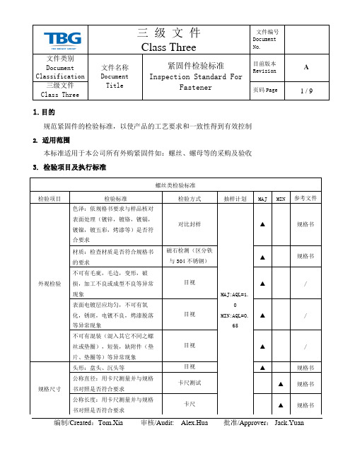
文件类别Document Classification 文件名称DocumentTitle紧固件检验标准Inspection Standard ForFastener目前版本RevisionA三级文件Class Three页码Page 1 / 9 1.目的规范紧固件的检验标准,以使产品的工艺要求和一致性得到有效控制2. 适用范围本标准适用于本公司所有外购紧固件如:螺丝、螺母等的采购及验收3.检验项目及执行标准螺丝类检验标准检验项目检验标准检验方式抽样计划MAJ MIN 参考文件外观检验色泽:依规格书要求与样品核对表面处理(镀锌,镀铬,镀镉,镀镍,镀五彩,烤漆等)是否符合要求对比封样MAJ:AQL=1.MIN:AQL=0.65▲规格书材质:检查材质是否符合规格书的要求磁石检测(区分铁与304不锈钢)▲规格书不可有毛疵,毛边,变形,破损,加工不良或成型不良等异常现象目视▲/表面电镀层应均匀,不可有氧化,锈斑,电镀不良,烤漆脱落等异常现象目视▲/不可有混装(混入其它不同之螺丝或垫圈),短装,缺附件(垫片、垫圈等)等异常现象目视▲/规格尺寸头形:盘头、沉头等目视▲规格书公称直径:用卡尺测量并与规格书对照是否符合要求卡尺测试▲规格书公称长度:用卡尺测量并与规格书对照是否符合要求卡尺▲规格书文件类别 Document Classification文件名称 Document Title紧固件检验标准Inspection Standard ForFastener 目前版本RevisionA 三级文件 Class Three页码Page2 / 9注释:○1中性盐水喷雾试验法:依据IEC 68-2-11之规范施行.测试条件: (Tested condition)a) 盐雾浓度(Consistency of salt spray): 5±1% b) 氯化钠(NaCl): 99.8%以上c) 试验温度(Test temperature): 35±2℃ d) 喷雾量(Spray amount): 1-2 ml/hr/80cm^2 e) 酸碱值: 35±2℃时,PH 值6.5-7.2 f) 试验时间: 24小时.g) 实验湿度(Test Humidity): 85%以上;h) 压缩空气压力(Compress air pressure): 1.25 kgf/cm^2○2扭力测试:螺钉试件的杆部(镀层或无镀层的)应夹紧在与螺钉螺纹相匹配的、开合的、螺纹模具或其他装置内;螺钉夹紧部分不应损伤,且至少有两扣完整螺纹伸出夹紧装置并除螺钉末端外至少有两扣完整螺纹夹紧在夹具内。
螺丝标准表
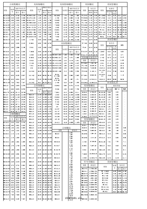
丝攻钻孔径
精度等级 规格
RH4.5.6 M1.0*0.25 M1.1*0.25 M1.2*0.25 M1.4*0.3 M1.6*0.35 M1.7*0.35 M1.8*0.35 M2.0*0.4 M2.2*0.45 M2.3*0.4 M2.5*0.45 M2.6*0.45 M3.0*0.5 M3.5*0.6 M4.0*0.7 M5.0*0.8 M6.0*1.0 M7.0*1.0 M8.0*1.25 M10*1.5 M10*1.25 M12*1.75 M12*1.25 0.86 0.96 1.06 1.24 1.41 1.51 1.61 1.78 1.95 2.08 2.25 2.35 2.73 3.17 3.62 4.56 5.45 6.45 7.31 9.18 9.31 11.04 11.31
公制粗螺纹
2级牙钻孔径 规格
M1.0*0.25 M1.1*0.25 M1.2*0.25 M1.4*0.3 M1.6*0.35 M1.7*0.35 M1.8*0.35 M2.0*0.4 M2.2*0.45 M2.3*0.4 M2.5*0.45 M2.6*0.45 M3.0*0.5 M3.0*0.6 M3.5*0.6 M4.0*0.7 M4.0*0.75 M4.5*0.75 M5.0*0.8 M6.0*0.8 M6.0*1.0 M7.0*1.0 M8.0*1.25 M9.0*1.25 M10*1.5 M11*1.5 M12*1.75 M14*2.0 M16*2.0 M18*2.5 M20*2.5 M22*2.5 M24*3.0 M27*3.0 M30*3.5
公制细螺纹
规格 标准径 2级牙钻孔径 最大 最小
11.153 10.917 11.520 11.400 12.676 12.376 13.153 12.917 13.676 13.376 14.153 13.917 14.676 14.376 15.153 14.917 15.676 15.376 16.153 15.917 16.210 15.835 16.676 16.376 17.153 16.917 18.210 17.835
标准kb2螺丝头径

标准kb2螺丝头径KB2螺丝是一种常用的螺丝类型,它具有一定的标准尺寸和严格的制造标准。
在实际应用中,人们常常需要了解KB2螺丝头径的标准规格,以便正确选用和使用。
接下来,我将详细介绍KB2螺丝头径的相关知识。
KB2螺丝头径是指螺丝头的直径,也可称为螺丝的大小。
在国际上,常用的螺纹标准有美国UNC、英国BSW、德国DIN等,其中DIN已发展为国际ISO标准,成为了世界各国通行的标准。
KB2螺丝头径的标准尺寸是指在ISO标准中规定的可选尺寸范围。
例如,KB2螺丝头径的标准尺寸可以是M1.6、M2、M2.5、M3等。
其中,字母"M"表示"metrisch",表示规定的是“公制”尺寸;数字表示螺丝头直径,单位是毫米(mm)。
KB2螺丝头径的标准尺寸不仅仅是为了统一螺丝规格,更是为了方便工业生产和交流。
标准化的螺丝头径尺寸在工业生产中有着广泛的应用,例如机械制造、汽车制造、电子设备、家居装饰等各个领域。
标准KB2螺丝头径的选用需要根据具体的需求来确定。
在选用螺丝时,需要考虑到使用环境、所需承受的载荷、紧固力度等因素。
一般来说,KB2螺丝头径越大,其承受的载荷也越大。
因此,在选择螺丝头径时,需要根据具体的应用情况进行选择。
此外,除了螺丝头径的标准尺寸外,螺丝长度也是需要注意的。
螺丝的长度会影响到螺丝的可用程度。
在选用螺丝时,需要根据实际情况确定螺丝长度,以确保螺丝能够完全穿过被连接物,并提供足够的螺纹长度来完成紧固。
在使用螺丝时,还需要注意螺丝连接的牢固性。
螺丝连接可以通过适当的扭矩控制来实现,以确保螺丝在使用过程中不易松动。
同时,还应使用适当的螺纹处理、螺纹润滑剂等辅助工具,以提高螺纹的连接性能。
综上所述,KB2螺丝头径是一种常用的螺丝规格,有着严格的制造标准和标准尺寸。
在实际应用中,了解和掌握KB2螺丝头径的标准规格对于正确选用和使用螺丝具有重要的意义。
希望通过以上的介绍,能够帮助读者更好地理解和应用KB2螺丝头径的相关知识。
TAPTITEII三角自攻螺丝标准

TAPTITEII三角自攻螺丝标准DUO-TAPTITE CORFLEX ?DUO-TAPTITEReduced In-Place Cost!!TAPTITE II ? and DUO-TAPTITE ? thread rolling screws reduce in-place fastener costs and provide vibration resistant assemblies. TAPTITE II ? and DUO-TAPTITE ? thread rolling screws are used to create strong, uniform load carrying internal threads into untapped nut members upon installation. When REMINC developed the original TAPTITE ? TRILOBULAR? shape thread rolling screw, it revolutionized the use of threaded fasteners in high production assembly. Assembly efficiency and joint performance along with lower in-place fasten-ing cost, havebeen the benefits of using TAPTITE ? screws. TAPTITE II ? and DUO-TAPTITE ? screws and bolts continue these benefits along with meeting the quality and performance needs of the future.Lower In-Place Fastening CostsOnly 15% of the total in-place cost of a fastening is the cost of the screw or bolt. TAPTITE II ? and DUO-TAPTITE ? screws and bolts lower the cost of the remaining 85%.The following is a list of some of the cost-savings advantages of using TAPTITE II ? and DUO-TAPTITE ? thread rolling screws.-Elimination of separate tapping operations and associated costs. -Built-in resistance to vibrational loosening eliminates the need for lock washers, adhesives, or plastic patches and plugs. - Generates stronger mating threads with uninterrupted grain flow due to work hardening of the nut for higher stripping resistance. -Accepts larger pilot hole variations than drilled and tapped holes. -Works in punched, drilled, cored and extruded holes in many different metals. -With use of CORFLEX ? metallurgy, can be provided in grade strengths of high tensile bolts for use in struc-tural applications in deep thread lengths of engagement. -No assembly line cross threading. -Prevailing torque often equals or exceeds locking screw standards. - Manufactured to REMINC standards all over the world by over 68 of the world’s leading fastener, fastenerprocessing and tooling companies.Originators of the TRILOBULAR? Family of Fasteners Providing Technical Support, Marketing Support and Innovative Fastener DesignCOPYRIGHT 2001, Research Engineering & Manufacturing Inc.level bolts are required. COPYRIGHT 2001, Research Engineering & Manufacturing Inc.Why TAPTITE II ? Over TAPTITE ?Screws? TAPTITE II ? screws bring benefits to both fastener manufacturer and end user. TAPTITE II ? screws were designed to: - Provide a more efficient manufacturing method and tool design to result in a more consistent product.- Be applicable to the quality and SPCphilosophies of today’s market by utilizing the capabilities of today’s state of the art tooling and fastener manufacturing equipment. - Provide more consistent torque performance, lowerthread forming torque and lower end load necessary to initiate thread forming, thanany other thread forming or thread rollingscrew including the original TAPTITE ? screw.Behind the scenes, REMINC has provided its licensed manufacturers with a total quality system for manu-facturing TAPTITE II ? fasteners. Included are design and processing failure mode and effects analysis pro-cedures, statistical in process control data collectionsystem, and improved inspection procedures and cri-teria. Although all REMINC products are designed for consistent manufacture and performance, TAPTITE II ? fasteners were physically re-designed tomeet the above quality system, to be the quality flag-ship of TRILOBULAR? products.Note: TAPTITE II ? is often designated TYPE TT AND TT-II“The Controllable Product ?”COPYRIGHT 2001, Research Engineering & Manufacturing Inc.Better starting stability – Axial AlignmentLess misalignment at start of driving operation . . . the self-aligning characteristic of DUO-TAPTITE ? screws reduces operator fatigue; eliminates interruptions in produc-tion; adds speed to every fastening opera-tion. Suitable for automated and robotic assembly. B – Higher prevailing torque Superior elastic action of a DUO-TAPTITE ? screw gives it better lock-ing characteristics than many fasteners specifically designed aslocking screws! Competitive round-bodied, thread-forming fasteners have nolocking torque. Graph shows comparison of DUO-TAPTITE ? screw with IFI-124 minimum requirement for self-locking screws.TYPICAL ANGULARITYLower starting end pressureLower starting end pressure combines with lower driving torque to reduce time and power costs right down the line. A –Higher strip-to-drive ratio The higher, more uniform, strip-to-drive torque ratio of DUO-TAPTITEscrews pro-vides a built-in safety factor against over-driving. Eliminates broken screws, dam-aged mating threads and inferior fastenings.Torque-tension comparison M8 x 1.25 DUO-TAPTITE ? vs.TAPTITE ? FastenerSuperior tension at any given applied torque (with normal clamping pressure) is a major factor in the better holding capa-bility of a DUO-TAPTITE ? screw.NOTE: All screws were tested in unthreaded weld nuts of uniform hardness (Rockwell B 82-84) hav-ing 7.1mm hole diameters. End pressure wasmanually developed, measured and recorded by anelectronic load cell and recorder. Drive, prevailingand strip torque values, and torque-tension valueswere measured with a GSE torque cell and re-corded on a BLH electronic recorder. All test datais based on 5/16 - 18 or M8 x 1.25 screws.COPYRIGHT 2001, Research Engineering & Manufacturing Inc.Suggested hole sizes for TAPTITE II ? & DUO-TAPTITEScrews and Bolts at various percentages of thread engagementEXAMPLE - The shaded areaindicates that an M5 - 0.8 screw size in a 4.58 hole size provides 80% threadengagement.Because the above values are based on a linear relation between hole size and percentage thread engagement, the hole data becomes less accurate for engagements less than 70%.Note also, these hole sizes are based on the U.S. basic thread depth of .6495 times the pitch and are calculated using nominal screw diameters.Hole = D - (0.6495 x P x %), where D = nominal screw diameter.(1) Pilot holes listed under 90% & 85% (Thread Percent) also recommended for single punch extruded holes.See Page 11For Pilot Hole Tolerance in terms of thread percentage, we suggest +5% to -10% of the nominal value, percent thread value.EXAMPLE: If 80% is the percent thread for the nominal hole, the minimum hole would yield 85% thread and themaximum hole would yield 70% thread.COPYRIGHT 2001, Research Engineering & Manufacturing Inc.Recommended pilot hole sizes forTAPTITE II ? & DUO-TAPTITE ?Screws and Bolts for steel nut member thicknesses (Expressed in terms of screw diameters)APPLICATION DUTY CLASS - A general term used here to group material thickness in terms of screw diameters. For example, the average material thicknesslisted under "medium-heavy" equals 75% of the screw diameter.COPYRIGHT 2001, Research Engineering & Manufacturing Inc.NOTES: - Torque values for metric sizes in New-ton-meters - Torque values for inch sizes in pound-inches - Plate dimensions for metric sizes in mil-limeters and for inch sizes in inches - Torque values were developed using hex washer head screws,zinc plated plus lubricity wax, driven at low speed underlaboratory-controlled conditions. - Values shown represent the above con-ditions only and should not be used in lieu of proper application testing. The data is presented to provide the user with an estimate of what could be achieved in an actual application having a thicker or thinner nut member harder or softer material, different hole or fas-tener all contribute to variations in torque performance. - Recommended tightening torque is in-tended to induce approximately 30,000 to 50,000 psi clamping force. - Prevailing first removal torque, the torque necessary to remove the screw after the head has been un-seated, is an indication of TAPTITE II ? screws inherent resistance of free turning which is an indication of resistance to loosen-ing under vibration, even without screw head being seated. * Indicates probability that nut threads will strip. ? Indicates probability that screw will break.COPYRIGHT 2001, Research Engineering & Manufacturing Inc.The above hole sizes are suggested starting points to be confirmed by actual testing. Extrusion Dimensions can vary due to tooling design and material being extruded.Approximate Material Thickness "T"Suggested extruded holes in light-gauge steel for TAPTITE II ? and DUO-TAPTITE ?Screws & Bolts (Continued from page 11)COPYRIGHT 2001, Research Engineering & Manufacturing Inc.Lengths greater than 25mm ± 1.3mmCOPYRIGHT 2001, Research Engineering & Manufacturing Inc.Self-aligning point feature‘finds’ the holes, lines them upand fastens them in oneoperation.COPYRIGHT 2001, Research Engineering & Manufacturing Inc.TEST PARAMETERS -Test material: cold-rolled draw qualityaluminum killed steel platehardened to Rb 50-55Test washer: .063 thick steelClearance hole: .180(#6), .200(#8), .220(#10),.280(1/4”)Drive speed: 250 RPM under loadDriver end load: 8lbs.- These values may vary proportionately to application.Smaller hole sizes for example, will increase drive, first off,strip torques, etc. Material thickness will also effect torque/ tension values as indicated in the table. These values were derived from averages of over 1800 laboratory tests under specific conditions. These values are to be used only as aguide since actual application performance results may vary.Reusable - Subjecting the POWERLOK? screw to increasingclamp load results in continuously in-creasing thread flankcontact so that unit pressure between mating surfaces tends to remain constant, an important factor in diminishing galling and abra-sion. Together with the burnishing action of the TRILOBULAR? crests means continued locking ef-fectiveness, after repeated insertions and removals. Locking performance - Will meet or exceed IFI 124 (inch) or IFI 524 (metric) Specifications for Pre-vailing Torque Locking Screws. Transverse vibration test data available upon request. Actual perform-ance will vary depending on effective finish lubricity and nut condition.No special taps - You save time and money by using a regular nut or Class 2B (6G) tapped hole. POWERLOK? is precision made - so the hole thread doesn’t have to be. Applications - Widely used in automotive and other mass-assembly operations. You can use POWERLOK?screws wherever you need reliable vibration resistance, continued high performance, despite repeated assem-bly/disassembly using normal tapped holes. They can be used in pre-tapped holes in ductile metals. STANDARD MATERIAL - Depending on part size, low carbon, medium carbon or alloy steel is selected. Then the steel is hardened and tempered to the optimum combination of tensile strength and toughness. Ten-sile or torsional strength can be more than twice that of machine screws. Screws can be made in strength levels to suit a wide range of application requirements. Property Class 10.9 is often preferred. Finishes can be supplied as required.The PLASTITE ? family of TRILOBULAR? screws for fastening in plastic The following is intended as a guide tochoosing threaded fasteners which will provide optimum application and per-formance characteristics in a wide range of plastics. It contains detailed information on PLASTITE ? thread- rolling screws. Because of the variations in the manu-facture of individual grades of plastics,particularly in the quantity of filler used, it is imperative that tests be conducted on each proposed application by a com-petent engineering laboratory. REMINC/CONTI’s network of licensees provide this testing service usually wit out obligation. This provides the design engineer with recommendations in the following areas: type of fasteners,quantity and sizes, design of the fasten-ing site or boss, hole sizes. Torque val-ues needed for power tool settings dur-ing assembly, including: drive, strip, seating, breakaway and prevailing off torque. A written report on the test re- sults is usually provided.How the TRILOBULAR? familyoptimizes fastener performance and lowers in-place costs. PLASTITE ? TRILOBULAR? thread-rolling screws were developed specifi-cally for use in plastics. They combine a unique TRILOBULAR? cross-sectionalform with deep, wide, spaced threads. Easier to drive. Three swaging lobes with full relief of the thread form reduce driving effort and operator fatigue. More holding power . The three-lobed design of PLASTITE ? screws takes full advantage of the cold flow characteris-tics of many plastics by allowing plastic material to recover and fill in between the lobes. This establishes maximum resistance to vibrational loosening. In addition, the screws’ deep, coarselyspaced threads provide a heavier shear area and deeperthread engagement in the plastic, further enhancing holding capabilities. COPYRIGHT 2001, Research Engineering & Manufacturing Inc.Size #2-#12Sizes M2-M5FINISH:Over 3/4"± .050"Over 20mm ± 1.3As Requested Over 1/4" Dia.M6-M8All Lengths ± .050"All Lengths ± 1.3COPYRIGHT 2001, Research Engineering & Manufacturing Inc.COPYRIGHT 2001, Research Engineering & Manufacturing Inc.1. Size/TPI –The PLASTITE ? 48-2 screw size designation combines the commonly used numerical screw size with the major diameter (Max. “D”) as measured with ordi-nary micrometers, followed by thenumber of threads per inch. 2. Recommended pilot hole sizes are subject to variation dependent on depth of engagement, ease of driving required and material being tapped. Users of PLASTITE ? 48-2 screws should perform their own test to determine the most efficient pilot hole size for their own particular use, or contact the appli-cation engineering department of a qualified supplier or REMINC.MATERIAL:Low Carbon Steel,Suitably Hardened and Tempered FINISH:As Requested LENGTH TOLERANCES Nom.Length Tol.Thru 3/4"± .030"Over 3/4"± .050"Over 1/4" Dia.All Lengths ± .050"。
螺丝标准
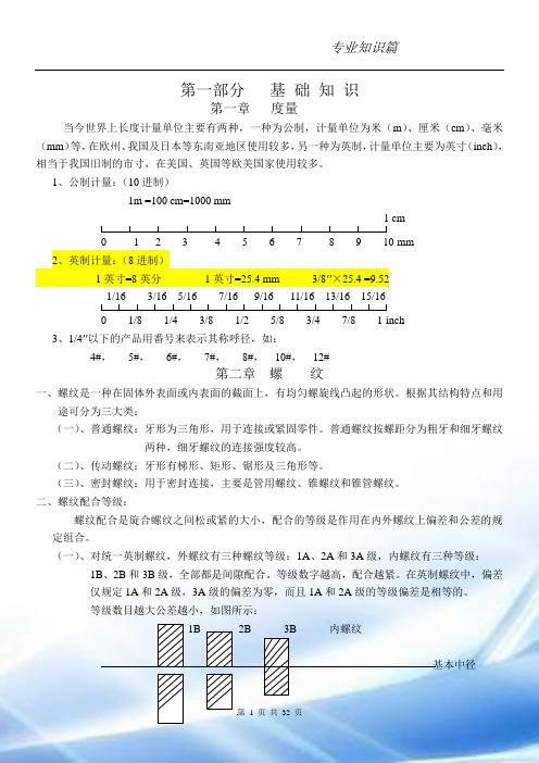
第一部分基础知识第一章度量当今世界上长度计量单位主要有两种,一种为公制,计量单位为米(m)、厘米(cm)、毫米(mm)等,在欧州、我国及日本等东南亚地区使用较多,另一种为英制,计量单位主要为英寸(inch),相当于我国旧制的市寸,在美国、英国等欧美国家使用较多。
1、公制计量:(10进制)1m =100 cm=1000 mm0 1 2 3 4 5 6 7 8 9 10 mm2、英制计量:(8进制)1英寸=8英分1英寸=25.4 mm 3/8''×25.4 =9.520 1/8 1/4 3/8 1/2 5/8 3/4 7/8 1 inch3、1/4''以下的产品用番号来表示其称呼径,如:4#,5#,6#,7#,8#,10#,12#第二章螺纹一、螺纹是一种在固体外表面或内表面的截面上,有均匀螺旋线凸起的形状。
根据其结构特点和用途可分为三大类:(一)、普通螺纹:牙形为三角形,用于连接或紧固零件。
普通螺纹按螺距分为粗牙和细牙螺纹两种,细牙螺纹的连接强度较高。
(二)、传动螺纹:牙形有梯形、矩形、锯形及三角形等。
(三)、密封螺纹:用于密封连接,主要是管用螺纹、锥螺纹和锥管螺纹。
二、螺纹配合等级:螺纹配合是旋合螺纹之间松或紧的大小,配合的等级是作用在内外螺纹上偏差和公差的规定组合。
(一)、对统一英制螺纹,外螺纹有三种螺纹等级:1A、2A和3A级,内螺纹有三种等级:1B、2B和3B级,全部都是间隙配合。
等级数字越高,配合越紧。
在英制螺纹中,偏差仅规定1A和2A级,3A级的偏差为零,而且1A和2A级的等级偏差是相等的。
等级数目越大公差越小,如图所示:1B 2B 3B 内螺纹基本中径3A 外螺纹2A1A1、1A和1B级,非常松的公差等级,其适用于内外螺纹的允差配合。
2、2A和2B级,是英制系列机械紧固件规定最通用的螺纹公差等级。
3、3A和3B级,旋合形成最紧的配合,适用于公差紧的紧固件,用于安全性的关键设计。
TAPTITE II 三角自攻螺丝标准
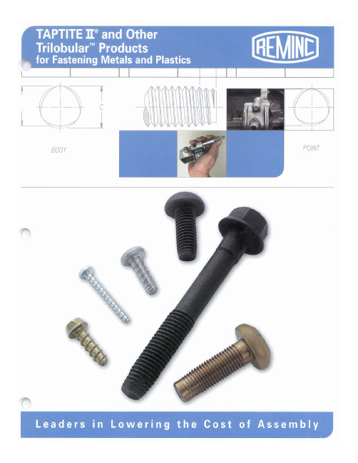
DUO-TAPTITE CORFLEX ®DUO-TAPTITEReduced In-Place Cost!!TAPTITE II ® and DUO-TAPTITE ® thread rolling screws reduce in-place fastener costs and provide vibration resistant assemblies. TAPTITE II ® and DUO-TAPTITE ® thread rolling screws are used to create strong, uniform load carrying internal threads into untapped nut members upon installation. When REMINC developed the original TAPTITE ® TRILOBULAR™ shape thread rolling screw, it revolutionized the use of threaded fasteners in high production assembly. Assembly efficiency and joint performance along with lower in-place fasten-ing cost, have been the benefits of using TAPTITE ® screws. TAPTITE II ® and DUO-TAPTITE ® screws and bolts continue these benefits along with meeting the quality and performance needs of the future.Lower In-Place Fastening CostsOnly 15% of the total in-place cost of a fastening is the cost of the screw or bolt. TAPTITE II ® and DUO-TAPTITE ® screws and bolts lower the cost of the remaining 85%.The following is a list of some of the cost-savings advantages of using TAPTITE II ® and DUO-TAPTITE ® thread rolling screws.-Elimination of separate tapping operations and associated costs. -Built-in resistance to vibrational loosening eliminates the need for lock washers, adhesives, or plastic patches and plugs. -Generates stronger mating threads with uninterrupted grain flow due to work hardening of the nut for higher stripping resistance. -Accepts larger pilot hole variations than drilled and tapped holes. -Works in punched, drilled, cored and extruded holes in many different metals. -With use of CORFLEX ® metallurgy, can be provided in grade strengths of high tensile bolts for use in struc-tural applications in deep thread lengths of engagement. -No assembly line cross threading. -Prevailing torque often equals or exceeds locking screw standards. - Manufactured to REMINC standards all over the world by over 68 of the world’s leading fastener, fastenerprocessing and tooling companies.Originators of the TRILOBULAR™ Family of Fasteners Providing Technical Support, Marketing Support and Innovative Fastener DesignCOPYRIGHT 2001, Research Engineering & Manufacturing Inc.level bolts are required. COPYRIGHT 2001, Research Engineering & Manufacturing Inc.Why TAPTITE II ® Over TAPTITE ®Screws? TAPTITE II ® screws bring benefits to both fastener manufacturer and end user. TAPTITE II ® screws were designed to:- Provide a more efficient manufacturing method and tool design to result in a more consistent product.- Be applicable to the quality and SPCphilosophies of today’s market by utilizing the capabilities of today’s state of the art tooling and fastener manufacturing equipment. - Provide more consistent torque performance, lower thread forming torque and lower end load necessary to initiate thread forming, thanany other thread forming or thread rollingscrew including the original TAPTITE ® screw.Behind the scenes, REMINC has provided its licensed manufacturers with a total quality system for manu-facturing TAPTITE II ® fasteners. Included are design and processing failure mode and effects analysis pro-cedures, statistical in process control data collectionsystem, and improved inspection procedures and cri-teria. Although all REMINC products are designed for consistent manufacture and performance, TAPTITE II ® fasteners were physically re-designed tomeet the above quality system, to be the quality flag-ship of TRILOBULAR™ products.Note: TAPTITE II ® is often designated TYPE TT AND TT-II“The Controllable Product ®”COPYRIGHT 2001, Research Engineering & Manufacturing Inc.Better starting stability – Axial AlignmentLess misalignment at start of driving operation . . . the self-aligning characteristic of DUO-TAPTITE ® screws reduces operator fatigue; eliminates interruptions in produc-tion; adds speed to every fastening opera-tion. Suitable for automated and robotic assembly. B – Higher prevailing torque Superior elastic action of a DUO-TAPTITE ® screw gives it better lock-ing characteristics than many fasteners specifically designed aslocking screws! Competitive round-bodied, thread-forming fasteners have nolocking torque. Graph shows comparison of DUO-TAPTITE ® screw with IFI-124 minimum requirement for self-locking screws.TYPICAL ANGULARITY** Starting angle of four specimens of each type measured at 20x full size on an optical comparator.Lower starting end pressureLower starting end pressure combines with lower driving torque to reduce time and power costs right down the line. A – Higher strip-to-drive ratio The higher, more uniform, strip-to-drive torque ratio of DUO-TAPTITE® screws pro-vides a built-in safety factor against over-driving. Eliminates broken screws, dam-aged mating threads and inferior fastenings.Torque-tension comparison M8 x 1.25 DUO-TAPTITE ® vs.TAPTITE ® FastenerSuperior tension at any given applied torque (with normal clamping pressure) is a major factor in the better holding capa-bility of a DUO-TAPTITE ® screw.NOTE: All screws were tested in unthreaded weld nuts of uniform hardness (Rockwell B 82-84) hav-ing 7.1mm hole diameters. End pressure wasmanually developed, measured and recorded by anelectronic load cell and recorder. Drive, prevailingand strip torque values, and torque-tension valueswere measured with a GSE torque cell and re-corded on a BLH electronic recorder. All test datais based on 5/16 - 18 or M8 x 1.25 screws.COPYRIGHT 2001, Research Engineering & Manufacturing Inc.Suggested hole sizes for TAPTITE II ® & DUO-TAPTITE®Screws and Bolts at various percentages of thread engagementEXAMPLE - The shaded areaindicates that an M5 - 0.8 screw size in a 4.58 hole size provides 80% threadengagement.Because the above values are based on a linear relation between hole size and percentage thread engagement, the hole data becomes less accurate for engagements less than 70%.Note also, these hole sizes are based on the U.S. basic thread depth of .6495 times the pitch and are calculated usingnominal screw diameters.Hole = D - (0.6495 x P x %), where D = nominal screw diameter.(1) Pilot holes listed under 90% & 85% (Thread Percent) also recommended for single punch extruded holes.See Page 11For Pilot Hole Tolerance in terms of thread percentage, we suggest +5% to -10% of the nominal value, percent threadvalue.EXAMPLE: If 80% is the percent thread for the nominal hole, the minimum hole would yield 85% thread and themaximum hole would yield 70% thread.COPYRIGHT 2001, Research Engineering & Manufacturing Inc.Recommended pilot hole sizes forTAPTITE II ® & DUO-TAPTITE ®Screws and Bolts for steel nut member thicknesses (Expressed in terms of screw diameters)APPLICATION DUTY CLASS - A general term used here to group material thickness in terms of screw diameters. For example, the average material thickness listed under "medium-heavy" equals 75% of the screw diameter.COPYRIGHT 2001, Research Engineering & Manufacturing Inc.Typical Torque Performance of TAPTITE II ®Screws in Cold Rolled Steel COPYRIGHT 2001, Research Engineering & Manufacturing Inc. NOTES: - Torque values for metric sizes in New-ton-meters - Torque values for inch sizes in pound-inches - Plate dimensions for metric sizes in mil-limeters and for inch sizes in inches - Torque values were developed using hex washer head screws, zinc plated plus lubricity wax, driven at low speed under laboratory-controlled conditions. - Values shown represent the above con-ditions only and should not be used in lieu of proper application testing. The data is presented to provide the user with an estimate of what could be achieved in an actual application having a thicker or thinner nut member harder or softer material, different hole or fas-tener all contribute to variations in torque performance. - Recommended tightening torque is in-tended to induce approximately 30,000 to 50,000 psi clamping force. - Prevailing first removal torque, the torque necessary to remove the screw after the head has been un-seated, is an indication of TAPTITE II ® screws inherent resistance of free turning which is an indication of resistance to loosen-ing under vibration, even without screw head being seated. * Indicates probability that nut threads will strip. † Indicates probability that screw will break.COPYRIGHT 2001, Research Engineering & Manufacturing Inc.The above hole sizes are suggested starting points to be confirmed by actual testing. Extrusion Dimensions can vary due to tooling design and material being extruded.Approximate Material Thickness "T"Suggested extruded holes in light-gauge steel for TAPTITE II ® and DUO-TAPTITE ® Screws & Bolts (Continued from page 11)COPYRIGHT 2001, Research Engineering & Manufacturing Inc.Lengths greater than 25mm ± 1.3mmCOPYRIGHT 2001, Research Engineering & Manufacturing Inc.Self-aligning point feature‘finds’ the holes, lines them upand fastens them in oneoperation.COPYRIGHT 2001, Research Engineering & Manufacturing Inc.TEST PARAMETERS -Test material: cold-rolled draw qualityaluminum killed steel platehardened to Rb 50-55Test washer: .063 thick steelClearance hole: .180(#6), .200(#8), .220(#10),.280(1/4”)Drive speed: 250 RPM under loadDriver end load: 8lbs.- These values may vary proportionately to application.Smaller hole sizes for example, will increase drive, first off,strip torques, etc. Material thickness will also effect torque/tension values as indicated in the table. These values werederived from averages of over 1800 laboratory tests underspecific conditions. These values are to be used only as aguide since actual application performance results may vary.Exceed IFI locking screw standards Have locking action you can’t wear out!Reusable - Subjecting the POWERLOK® screw to increasing clamp load results in continuously in-creasing thread flank contact so that unit pressure between mating surfaces tends to remain constant, an important factor in diminishing galling and abra-sion. Together with the burnishing action of the TRILOBULAR™ crests means continued locking ef-fectiveness, after repeated insertions and removals. Locking performance - Will meet or exceed IFI 124 (inch) or IFI 524 (metric) Specifications for Pre-vailing Torque Locking Screws. Transverse vibration test data available upon request. Actual perform-ance will vary depending on effective finish lubricity and nut condition.No special taps - You save time and money by using a regular nut or Class 2B (6G) tapped hole. POWERLOK® is precision made - so the hole thread doesn’t have to be. Applications - Widely used in automotive and other mass-assembly operations. You can use POWERLOK®screws wherever you need reliable vibration resistance, continued high performance, despite repeated assem-bly/disassembly using normal tapped holes. They can be used in pre-tapped holes in ductile metals. STANDARD MATERIAL - Depending on part size, low carbon, medium carbon or alloy steel is selected. Then the steel is hardened and tempered to the optimum combination of tensile strength and toughness. Ten-sile or torsional strength can be more than twice that of machine screws. Screws can be made in strength levels to suit a wide range of application requirements. Property Class 10.9 is often preferred. Finishes can be supplied as required.The PLASTITE ® family of TRILOBULAR™ screws for fastening in plasticThe following is intended as a guide to choosing threaded fasteners which will provide optimum application and per-formance characteristics in a wide range of plastics. It contains detailed information on PLASTITE ® thread-rolling screws.Because of the variations in the manu-facture of individual grades of plastics, particularly in the quantity of filler used, it is imperative that tests be conducted on each proposed application by a com-petent engineering laboratory.REMINC/CONTI’s network of licensees provide this testing service usually wit out obligation. This provides the design engineer with recommendations in the following areas: type of fasteners, quantity and sizes, design of the fasten-ing site or boss, hole sizes. Torque val-ues needed for power tool settings dur-ing assembly, including: drive, strip, seating, breakaway and prevailing off torque. A written report on the test re-sults is usually provided.How the TRILOBULAR™ familyoptimizes fastener performance and lowers in-place costs.PLASTITE ® TRILOBULAR™ thread-rolling screws were developed specifi-cally for use in plastics. They combine a unique TRILOBULAR™ cross-sectional form with deep, wide, spaced threads.Easier to drive. Three swaging lobes with full relief of the thread form reduce driving effort and operator fatigue.More holding power . The three-lobed design of PLASTITE ® screws takes full advantage of the cold flow characteris-tics of many plastics by allowing plastic material to recover and fill in between the lobes. This establishes maximum resistance to vibrational loosening. In addition, the screws’ deep, coarsely spaced threads provide a heavier shear area and deeper thread engagement in the plastic, further enhancing holdingcapabilities.COPYRIGHT 2001, Research Engineering & Manufacturing Inc.Size #2-#12Sizes M2-M5FINISH:Over 3/4"± .050"Over 20mm ± 1.3As RequestedOver 1/4" Dia.M6-M8All Lengths ± .050"All Lengths± 1.3®®COPYRIGHT 2001, Research Engineering & Manufacturing Inc.COPYRIGHT 2001, Research Engineering & Manufacturing Inc.1. Size/TPI – The PLASTITE ® 48-2 screw size designation combines the commonly used numerical screw size with the major diameter (Max. “D”) as measured with ordi-nary micrometers, followed by the number of threads per inch.2.Recommended pilot hole sizes are subject to variation dependent on depth of engagement, ease of driving required and material being tapped. Users of PLASTITE ® 48-2 screws should perform their own test to determine the most efficientpilot hole size for their own particular use, or contact the appli-cation engineering department of a qualified supplier or REMINC.MATERIAL:Low Carbon Steel,Suitably Hardened and TemperedFINISH:As Requested LENGTH TOLERANCES Nom.Length Tol.Thru 3/4"± .030"Over 3/4"± .050"Over 1/4" Dia.All Lengths ± .050"MATERIAL:Low Carbon Steel,Suitably Hardenedand TemperedFINISH:As RequestedLENGTH TOLERANCESNom.Length Tol.Thru 3/4"± .030"Over 3/4"± .050"Over 1/4" Dia.All Lengths± .050" Recommended length of thread engage-ment is two screw diameters minimum.The range of suggested hole sizes is largebecause of the range of densities in ther-moplastic compounds and length of threadengagements. Generally low density plas-tic can use smaller hole diameters. Longlength of engagement (2 to 3 diameters)require larger holes.Tamper Resistant yet Removablefor Service.PUSHTITE® II fasteners are normally avail-able with a drive system in the head forremoval, adjustment or final tightening.Where adjustment or removal is not re-quired they are available without slot, re-cess or socket in the head.Performance in graphs is basedon the average of several testsin different materials.COPYRIGHT 2001, Research Engineering & Manufacturing Inc.CORFLEX ® - EXPANDS THE COST SAVINGS HORIZON TAPTITE II ®, TAPTITE ® CA and DUO-TAPTITE ® screws are capable of performing in large diameter sizes in deep thread engagements. The past limitation in exploiting the in-place c o s t s a v i n g s o f l a r g e s i z e TRILOBULAR™ products was that the required screw hardness was achieved through case hardening. Case harden-ing is detrimental to structural appli-cations as the fastener would be sus-ceptible to differing modes of “brittle” failure. Tougher! That’s the whole reason why CORFLEX ® fasteners were invented! Screws come in many different strengths; ordinary machine screws are manufactured from non-hardened, low-carbon steel. Regular tapping screws are manufac-tured from low-carbon steel case hardened to 107 ksi minimum strength. Metric Grade 9.8 or inch Grade 5 ma-chine screws are manufactured to 930 MPA and 120 ksi minimum respec-tively. They are manufactured from low to medium carbon alloy or boron intensified steel. Metric Grade 10.9 or inch Grade 8 ma-chine screws are manufactured from medium carbon alloy steel to 1040 MPA and 150 ksi strength respec-tively.But until CORFLEX ®-I technology, there was no thread-forming orthread-rolling fastener with both the thread forming hardness of a tapping screw and the toughness of a grade strength machine screw!CORFLEX ®-I, TAPTITE II ®, TAPTITE ® CA and DUO-TAPTITE ® and screws and bolts are unique: They are manu-factured from 4037 alloy steel and custom heat treated throughout towhatever strength is required! Thiscould be Grade 8.8, 9.8, 10.9, 12.9 or anything in between! CORFLEX ®-I screws are neutral hard-ened so the bolt or screw has uniformstructure similar to grade strength machine screws. Then, after bolt strength is heat treated to the re-quired properties of applications, the thread rolling zone is induction hard-ened for thread forming capability.This selective zone heat treating isdone on customized automatic feed induction hardening machines. It is this two stage heat treatment that makes the CORFLEX ®-I version TAPTITE II ®, TAPTITE ® CA and DUO-TAPTITE ® screws unique; strong and tough in the load bearing areas but very hard in the thread rolling area. The combination of strength and t o u g h n e s s e n a b l e s , t h e CORFLEX ®-I screw to bend without breaking and withstand alternating or cyclical loads. Tension can be applied and relaxed almost indefinitely with-out encouraging fatigue cracking. C O R F L E X ®-N v e r s i o n s o f TAPTITE II ®, TAPTITE ® CA and DUO-TAPTITE ® screws are neutral hardened and tempered to desired strength or grade level. A subsequent zone hardening of the thread rollingpoint is not necessary as the intended use of CORFLEX ®-N screws and bolts is in soft ductile non-ferrous materials, such as zinc and aluminum. Addition-ally, POWERLOK ® screws are heat treated to CORFLEX ®-N Metallurgy. Above is an illustration of the excellent thread forming capability of a CORFLEX ®-I TAPTITE II ® bolt in producing deep threads of one diameter length or greater in heavy (multiple punch) extrusions as required for structural applications. COPYRIGHT 2001, Research Engineering & Manufacturing Inc. THE TOUGHER THREAD ROLLING SCREWSHEAT TAILORED FOR EXTRA RUGGEDNESS Pin-point precision of high hardness zone in axial section of CORFLEX ®-I TAPTITE II ® screw is shown by crescent shaped area in chemically etched mounts. “Punishment Proved” Performance: The unusual tapping and fastening capabilities of the CORFLEX ®-I screw are illustrated by this test. A ½-13 diameter CORFLEX®-I screw withstands a 25° body bend after having formed an internal thread with a 95% engagement in a section of 5/8” thick-ness of cold rolled steel. CAN ANY OTHER SELF-THREADING SCREW DO AS MUCH?INSPECTION PROCEDURE: TRILOBULAR™ products can be checked with standard micrometers for D and 60° vee-anvil micrometers for C. Alternatively, C may be gauged using plain-hole ring gauges. These must have accurate holes as tabled for mini-mum and as tabled plus .025mm (.001 inch) for maximum.The values shown are for guidanceonly. They are not to be used for de-sign criteria. Their use and reliancethereon for any purpose by anyone isentirely voluntary and at the sole riskof the user. REMINC is not responsiblefor any loss, claim, or damage result-ing from their use. Consult our applica-tion engineers or the application engi-neering department of one of ourmany qualified producers for your spe-cific application data.ORDERING/SUPPLY:When ordering from qualifiedTRILOBULAR™ producers, be sure inall cases to specify thread size, nomi-nal length, head and point style,whether it is TAPTITE II® orDUO-TAPTITE® etc., strength grade ifCORFLEX®-N or CORFLEX®-I is in-volved, any other special features re-quired, finish and quantity.TECHNICAL ASSISTANCE:This brochure contains basic informa-tion needed to achieve the cost sav-ings potential of TRILOBULAR™ fas-teners.To obtain further assistance and a listof qualified manufacturers, callREMINC at 401-841-8880 or E-mail atreminc@.COPYRIGHT 2001, Research Engineering & Manufacturing Inc.Head Dimensions: All TRILOBULAR™screws and bolts can be provided with anystandard head style, to ISO, ANSI or anyother international standard.Lengths: TAPTITE II®, DUO-TAPTITE® andPOWERLOK® screws and bolts are manufac-tured to applicable local standards on threadlength and screw length. Tolerances listed inbrochure are suggested only. Due to thegreater manufacturing variation in producinggimlet pointed screws, EXTRUDE-TITE® andTAPTITE® CA screws are manufactured totolerancing as stated on Page 13. PLASTITE®and PUSHTITE® II screws are manufacturedto length tolerances as stated on Pages 18 -20.Available Sizes: Sizes listed are the mostpopular standard sizes. TRILOBULAR™ prod-ucts can be supplied in standard miniaturescrew and large bolt sizes not listed. Specialsize/pitch combinations are also available.Materials: TRILOBULAR™ screws and boltsare manufactured from low to medium car-bon steel in the case hardened version andfrom various grades of alloy steel to meet thegrade strength requirements of CORFLEX®-Iselective hardened version.Metallurgy: TAPTITE II® screws are sup-plied in two metallurgical categories; casehardened or selective hardened to REMINCCORFLEX® grade strength levels. Applicablestandards would include SAE-J81 for inchscrews and SAE-J1237 for metric.TAPTITE II® CORFLEX®-I screws can be sup-plied to metric grades equivalent to 8.8, 10.9and 12.9 and inch Grades 8 and 5 or to spe-cial hardness and toughness requirements.Case hardened fasteners are not recom-mended for use in die cast or extruded alumi-num or zinc particularly when galvanic condi-tions, severe load or thermal cycling is pre-sent. CORFLEX®-I or CORFLEX®-N are recom-mended for these conditions.POWERLOK® screws are manufactured tometric Grade 10.9 or inch Grade 8.POWERLOK® screws can be provided as casehardened but are not recommended unlessused in a light duty application.All TRILOBULAR™ products can be producedin various stainless steel grades or from non-ferrous materials. (Stainless steel and non-ferrous product have limitations on threadforming capabilities.)DISCLAIMER CLAUSEREGISTERED TRADEMARKS LICENSEDBY REMINC USED IN THIS BROCHURETAPTITE II®, TYPE TT®, DUO-TAPTITE®,EXTRUDE-TITE®, POWERLOK®, KLEERLOK®,THE CONTROLLABLE PRODUCT®, CORFLEX®,PLASTITE®, ENGINEERED FASTENINGS®Finish: TRILOBULAR™ screws and boltscan be supplied with all commercially avail-able finishes and coatings. Electroplatedfinishes should be avoided on high strengthgrades. The addition of a wax lubricant isrecommended on high surface friction fin-ishes such as zinc. Electroplated fastenersshould be baked.Options: All TRILOBULAR™ products canbe supplied with several optional configura-tions, i.e. with shoulders, dog points, andwith washer assembly. TAPTITE II®screws can be supplied with optional cap-tive point or with “CA” gimlet point (seePage 5).Optional Extras: Tables in this brochurecover only the standard, threadconfigurations and point styles available onT A P T I T E I I®/D U O-T A P T I T E®CORFLEX® parts. Many variations are pos-sible including:- Sems versions with captive washers.Extra large heads and/or underhead col-lars to suit individual needs.- Underhead earthing nibs to ensure earthc o n t i n u i t y t h r o u g h p a i n t e dsurfaces;- Unrolled root diameter dog points toassist location;- Unrolled pitch-diameter ‘captive’ dogpoints for extra security;- Partly threaded shanks for captivescrews in cover plates;- Security drive systems for tamper resis-tance.Performance: TAPTITE II® andDUO-TAPTITE® screws in either case hard-ened or CORFLEX® version meet or exceedthe performance requirements of SAE-J81,J1237, DIN 7500, GM 6171M,GM6202M,Ford WD-951 and 952, Ford ES-20003-S100 as well as several other automotive,OEM, and industrial specifications. POWER-LOK® screws meet the performance re-quirements of IFI-124 and 524.The following are aids to assist on the useof TAPTITE II® and DUO-TAPTITE® fasten-ers.Percent thread chart ……………… Page 8Pilot hole sizes ……………………… Page 9Typical torque performance ….. Page 10Typical single punchextruded holes ………… Pages 11 & 12Die cast cored holes …………..… Page 12CORFLEX® …………………….… Page 21RS Technologies Fastener TestEquipmentMeasures torque and tension vs.angle, combined with electronicdata acquisitionTukon Micro-Hardness TesterProvided micro-hardness andmicro-structure analysisJunkers Design TransverseVibration TesterSimulates accelerated serviceconditions to predict joint integrity.COPYRIGHT 2001, Research Engineering & Manufacturing Inc.。
螺丝标准
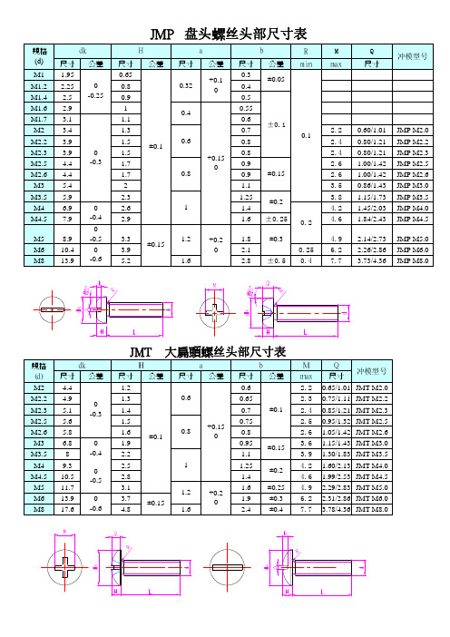
±0.15 ±0.2 ±0.25 ±0.3 ±0.5
JMR 圆头螺丝头部尺寸表
规格
M1 M1.2 M1.4 M1.6 M1.7 M2 M2.2 M2.3 M2.5 M2.6 M3 M3.5 M4 M4.5 M5 M6 M8 M R 尺寸 公差 尺寸 公差 尺寸 公差 尺寸 公差 min max 1.95 0 2.25 2.5 -0.25 2.9 3.1 3.4 3.9 0 3.9 -0.3 4.4 4.4 5.4 0 5.9 6.9 -0.4 0 7.9 8.9 -0.5 0 10.4 13.9 -0.6 0.8 0.45 +0.1 0.9 0.5 0.32 0 1 0.6 ±0.1 1.1 0.65 0.4 1.2 0.7 1.3 0.8 0.1 1.5 0.9 0.6 1.5 ±0.1 0.9 +0.15 ±0.15 1.7 1 0 1.7 1 0.8 2 1.2 ±0.2 2.3 1.4 2.6 1.6 ±0.25 1 3 1.9 0.2 ±0.3 3.4 2.1 1.2 +0.2 4 2.5 ±0.4 0.25 ±0.15 0 5.4 1.6 3.3 ±0.5 0.4
C 尺寸 公差 尺寸 公差 約 dk H
1.95 2.35 2.75 3.1 3.3 3.9 4.3 4.5 4.9 5.1 5.9 6.9 7.9 8.9 9.9 11.9 15.8 0 -0.25 0.6 0.1 0 0.7 0.85 -0.1 0.95 0.15 1 1.15 0 1.25 1.3 -0.15 0.2 1.4 1.45 1.65 0.25 1.9 0 2.2 -0.2 2.45 0.3 2.7 0 3.3 0.4 4.3 -0.3
0.35 0.4 ± 0.4 0.5 0.075 0.5 0.6 0.7 0.8 0.9 ±0.1 1 1.3 1.7 ±0.15 1.2 1.3 1.4 ±0.1 1.5 1.6 1.9 2.2 2.5 2.8 ±0.15 3.1 3.7 4.8 ±0.2 0.6 0.65 0.7 0.7 0.8 +0.15 0.85 0.8 0 1 1.15 1.3 1 1.5 1.7 1.2 +0.2 2 0 1.6 2.8 ±0.1 0.1 0.1 0.1 0.1 0.1 0.1 0.1 0.2 0.2 0.2 0.25 0.4 2.2 2.3 2.4 2.5 2.6 3.6 3.9 4.2 4.6 4.9 6.2 7.7
m20螺丝标准尺寸

m20螺丝标准尺寸M20螺丝标准尺寸。
M20螺丝是一种常见的紧固件,广泛应用于机械设备、建筑结构、汽车制造等领域。
M20螺丝的标准尺寸对于工程设计和生产制造具有重要意义。
本文将对M20螺丝的标准尺寸进行详细介绍,以便读者更好地了解和应用这一常用零部件。
M20螺丝的标准尺寸主要包括直径、螺距、长度等方面的参数。
首先,M20螺丝的直径是指螺丝外径的尺寸,通常为20mm。
其次,螺距是指螺丝螺纹的间距,对于M20螺丝来说,螺距通常为2.5mm。
此外,M20螺丝的长度根据具体的使用要求而定,常见的长度包括20mm、30mm、40mm等,也可以根据需要定制非标尺寸。
在实际应用中,选用合适的M20螺丝标准尺寸对于确保装配质量和使用性能至关重要。
如果螺丝直径过大或者过小,都会导致螺纹无法匹配或者承载能力不足;而螺距不合适则会影响螺丝的旋紧效果;螺丝长度过长或者过短也会影响装配的紧固效果和安全性。
因此,在设计和选择M20螺丝时,需要充分考虑实际使用环境和要求,合理确定螺丝的标准尺寸。
除了标准尺寸外,M20螺丝的材质和表面处理也是需要重点关注的问题。
常见的M20螺丝材质包括碳钢、合金钢、不锈钢等,不同的材质具有不同的强度和耐腐蚀性能,需要根据具体使用环境和要求进行选择。
此外,表面处理如镀锌、镀镍、磷化等也会影响螺丝的耐腐蚀性能和外观效果,需要根据具体要求进行选择。
总的来说,M20螺丝的标准尺寸是设计和选择过程中至关重要的一环,合理选择合适的尺寸可以确保装配质量和使用性能。
在实际应用中,需要充分考虑螺丝的直径、螺距、长度、材质和表面处理等因素,以便选用最合适的M20螺丝,从而满足工程设计和生产制造的要求。
通过本文对M20螺丝标准尺寸的介绍,相信读者对于这一常用零部件有了更深入的了解,能够在实际工作中更加准确地选择和应用M20螺丝,为工程设计和生产制造提供更好的支持和保障。
希望本文能够对读者有所帮助,谢谢阅读!。
常用螺栓的标准及规格表

M2.3 0.40 2.28 2.19 1.98 M2.5 0.45 2.48 2.38 2.15 M3.0 0.50 2.98 2.88 2.60 M3.5 0.60 3.47 3.36 3.02 国 M4.0 0.70 3.98 3.83 3.40 标 粗 M4.5 0.75 4.47 4.36 3.88 牙 M5.0 0.80 4.98 4.83 4.30 M6.0 1.00 5.97 5.82 5.18 60° M7.0 1.00 6.97 6.82 6.18 M8.0 1.25 7.96 7.79 7.02 M9.0 1.25 8.96 8.79 8.01 M10 1.50 9.96 9.77 8.84 M11 1.50 10.97 10.73 9.84 M12 1.75 11.95 11.76 10.7 M14 2.00 13.95 13.74 12.5 M16 2.00 15.95 15.74 14.5 M18 2.50 17.95 17.71 16.2 M20 2.50 19.95 19.71 18.2 M4.0 0.50 3.97 3.86 3.58 M4.5 0.50 4.47 4.36 4.07 M5.0 0.50 4.97 4.86 4.57 M6.0 0.75 5.97 5.85 5.41 M7.0 0.75 6.97 6.85 6.41 国 M8.0 1.00 7.97 7.83 7.24 标 M9.0 1.00 8.97 8.83 8.24 细 牙 M10 1.00 9.97 9.82 9.23 M10 1.25 9.96 9.81 9.07 60° M12 1.25 11.97 11.76 11.07 M12 1.50 11.96 11.79 10.89 M14 1.50 13.96 13.79 12.89 M16 1.50 15.96 15.79 14.89
- 1、下载文档前请自行甄别文档内容的完整性,平台不提供额外的编辑、内容补充、找答案等附加服务。
- 2、"仅部分预览"的文档,不可在线预览部分如存在完整性等问题,可反馈申请退款(可完整预览的文档不适用该条件!)。
- 3、如文档侵犯您的权益,请联系客服反馈,我们会尽快为您处理(人工客服工作时间:9:00-18:30)。
螺丝常见于机械,电器及建筑物等,一般为金属制造,呈圆筒形,表面刻有凹凸的沟,如一个环绕螺丝侧面的倾斜面,让螺丝可紧锁著螺丝帽或其他物件。
螺丝的顶部直径较大,可呈圆形或等六边形,让工具如螺丝起子或扳手可转动螺丝。
较突出的顶部亦令螺丝不会钻得太深入而穿过物料,及提高螺丝对物料的压力。
目录[隐藏]
1 基本注音
2 规格定义
3 螺丝型号
4 相关词条
5 螺丝相关中英文对照
6 参考资料
螺丝-基本注音
螺丝螺丝,luósī。
(screw)螺钉。
见“螺杆”
螺丝通常可随意移除或重新嵌紧而不损其效率,亦比钉提供更大的力量,也可重覆使用。
主要分类包括普通螺丝、自攻螺丝和膨胀螺丝三种。
螺丝-规格定义
螺丝一、螺纹种类:
A:三角螺纹( 60 度) :结合/ 锁紧
B:管用三角螺纹( 55 度):结合/ 锁紧
C:梯形螺纹( 30 or 29 度) :动力传动
D:方螺纹( 90 度) :动力传动
二、常用螺丝种类:
A:Machine Screw:机械螺丝
B:Tapping Screw:自攻螺丝(分使用于金属与使用于塑料二种)
B-1:Sheet Metal Tapping Screw (铁板牙自攻螺丝)
B-2:Plastic Tapping Screw( 塑料用,自攻螺丝)
C:Wooden Screw :木工螺丝
D:Drywall Screw :水泥墙螺丝
螺丝三、常见螺丝材质:
a、Low Carbon Steel :低碳钢
b、SS-304 :Stainless Steel 304
c、SS-302:Stainless Steel 302 :结构韧性较好
d、Aluminum 5052 :铝合金5052
d、Brass:黄铜
e、Bronze:青铜
f、UNS C11000 Copper:锑铜
四、常见螺丝规格与标示:
A、公制螺丝
B、美规螺丝
C、英制螺丝
A、公制机械螺丝:Metric
Ex、M3 x 6 –P P B:M3 机械螺丝,6mm 长,十字,圆扁头,镀黑。
Finish Code、外观处理规格
Head Code、头部外型
螺丝-螺丝型号
螺丝Drive Code:头部剖沟,特征型号
Length Code:螺丝长度(mm)
A-1:Thread Code:螺丝型号
公制螺丝直接以螺丝外径标示螺丝型号,
如M3 即螺丝外径为3。
00mm。
;M4 即螺丝外径为4。
00mm。
Metric Thread Size x Pitch:
Note:公制螺丝于螺丝型号后方,有时会注明螺丝牙距。
如M3x0。
5 ,M4x0。
70,M5x0。
8 ,M6x1。
但因为标准规范,通常不提。
螺丝A-2:Length Code:螺丝长度:
公制螺丝,直接标示螺丝长度,单位为mm。
螺丝之总长度标示,只计算头部以下之长度,不含头部高度。
但平头螺丝例外,其螺丝之总长度标示含头部高度。
A-3:Drive Code/ 头部剖沟,特征。
一般常用规格如下:
a、Slotted:一字( Minus )
b、Phillips:十字( Plus )
c、Phil-Slot:一字/十字
d、Hex Scoket:内六角
e、One Way:单向(只可锁入,不可退出)
A-4:Head Code/ 头部外型。
一般常用规格如下:
a、Flat:平头(锁入后,顶部与工作件齐平)
b、Oval:色拉头
c、Round:圆头
d、Pan:圆扁头
e、Truss:大圆扁头
f、Hex :六角头。
A-5:Finish Code/ 外观处理。
螺丝一般常用规格如下:
a、Z:Zine-Plated:镀锌
b、Ni:Ni-Plated:镀镍
c、Tin-Plated:镀锡
d、Zine Plated / Green Iridite:镀锌绿膜处理。
e、Radiant Plated:镀五彩
f、Passivate:抗氧化处理。
g、Alodial Finish:无外观处理
公制自攻螺丝:于品名后方直接标示Tapping Type。
Ex:M3 x 6 –PPB,Tapping Type:
M3 自攻螺丝,6mm 长,十字,圆扁头,镀黑。
一般以产品别或标示,再判断为Sheet Metal 或塑料部品使用。
B:美规螺丝。
a、一般以番号标示,如#2-56,#4-40,#6-32,#8-32,#10-24。
b、或以英制外径表示,
如0.086-56,0.112-40 ,0.138-32 ,0.164-32 ,0.190-24。
Ex:632 –8 –P P B:
Finish Code:外观处理规格
Head Code:头部外型
Drive Code:头部剖沟,特征型号
Length Code:螺丝长度
Thread Code:螺丝型号
B-1:Thread Code:螺丝型号
螺丝一般常用规格如下:
a、#2-56 (0.086-56):2 番56 牙
b 、#4-40 (0.112-40) :4 番40 牙
c、#6-32 (0.138-32) :6 番32 牙
d、#8-32 (0.164-32) :8 番32 牙
e、#10-24 (0.190-24):10 番24 牙
B-2:Length Code:螺丝长度
美规螺丝长度须经换算,才是公制mm尺寸。
换算公式:(Length Code / 32) x 25.40 = 公制长度mm
B-3,B-4,B-5 :标示方式与公制相同。
C:英制螺丝:
C-1:Thread Code:
标示皆将分母为8,再直接称分子之番号。
Ex:1/8 x 0.50 –PPB: 1 分牙螺丝x 0.50”长,PPB
Ex:5/16 x 0.50 –PPB = 2.5/8 x 0.50-PPB :2 分半牙螺丝x 0.50”长,PPB
Ex:5/32 x 0.50 –PPB =1.25/8 x 0.50-PPB: 1 分2 厘半螺丝x 0.50”长,PPB
Ex:1/4 x 0.50-PPB= 2/8 x 0.50-PPB: 2 分牙螺丝x 0.50”长,PPB
注:有时会标示粗牙或细牙。
UNF:细牙:电子业较常用。
螺丝UNC:粗牙:重机械结构较常用。
Ex:3/8 x 0.50 ,UNF –PPB: 3 分细牙螺丝x 0.50”长,PPB。
C-2:Length Code:
为英吋标示,须乘以25.40 换算为mm。
用扣规量,与公制牙型吻合是公制螺纹,与英制螺纹吻合是英制螺纹。
也可以用卡尺量螺纹的外径,和螺距。
公制螺纹外径是以毫米为单位,如6,8,10,12,18,20毫米等等螺距也是以毫米为单位,如0.5,0.75,1,1.5,2,3,等等
英制螺纹外径是以英寸为单位,(每英寸等于25.4毫米)如3/16,5/8,1/4,1/2,等等所以用公制卡尺量外径读数常带不规则的小数。
英制螺距是用每英寸含多少个牙表示。
把卡尺定在25.4毫米,把一个尺尖对齐螺纹牙尖,另一个尺尖如对齐螺纹牙尖就是英制螺纹,如对不齐螺纹牙尖应该是公制螺纹。
测量螺距时最好把螺纹的牙尖倒印在白粉笔上,粉笔上的印比较清晰,便于测量。
测公制螺距应该测量一段长度,如10,15,20,毫米等等,数一下含多少牙,算出螺距用英吋为单位规定螺纹规格的为英制螺纹,如:G1"。
用公制单位毫米规定螺纹规格的为公制螺纹。
如:M30。
英制是一英吋(24.5厘米)内有多少牙来定的,一般是55度角。
公制是两牙尖的间距是多少MM来定的螺距,一般是60度角。
