上海全锐 EA-1500使用说明书
PQ1500 操作手册说明书

PQ1500 OPERATION MANUAL“IMPORTANT SAFETY INSTRUCTIONS”“Read all instructions before using.”When using a sewing machine, basic safety precautions should always be taken,including the following:DANGER – To reduce the risk of electric shock.q The sewing machine should never be left unattended while plugged in. Always unplug the sewing machine from the electrical outlet immediately after using and before cleaning.q Always unplug before changing the light bulb. Replace bulb with same type rated 120V 15 watts for 120V model or rated 240V 15watts for 220-240V model. WARNING – To reduce the risk of burns, fire, electric shock, or injury.q Do not allow this sewing machine to be used as a toy. Close attention is necessary when the sewing machine is used by or near children.q Use this sewing machine only for its intended use as described in this manual. Use only accessories recommended by the manufacturer as contained in this manual. q Never operate this sewing machine if it has a damaged cord or plug, if it is not working properly, if it has been dropped or damaged, or dropped into water. Return the sewing machine to the nearest authorized dealer or service center for examination, repair, electrical or mechanical adjustment.q Never operate the sewing machine with any air openings blocked. Keep ventilation openings of the sewing machine and foot control free from the accumulation of lint, dust, and loose cloth.q Never drop or insert any object into any opening.q Do not use outdoors.q Do not operate where aerosol (spray) products are being used or where oxygen is being administered.q To disconnect, turn the main switch to the symbol “O” position which represents off, then remove plug from outlet.q Do not unplug by pulling on cord. To unplug, grasp the plug, not the cord.q Keep fingers away from all moving parts. Special care is required around the sewing machine needle.q Always use the proper needle plate. The wrong plate can cause the needle to break.q Do not use bent needles.q Do not pull or push fabric while stitching. It may deflect the needle causing it to break.q Turn off power to the machine by flipping the ON/OFF switch to the symbol “O” before making any adjustments in the needle area, such as threading the needle, changing the needle, threading the bobbin or changing the presser foot etc.q Always unplug the sewing machine from the electrical outlet when removing covers, lubricating, or when making any other user servicing adjustments mentioned in the instruction manual.q This sewing machine is not intended for use by young children or infirm persons without supervision.q Young children should be supervised to ensure that they do not play with this sewing machine.CAUTION For U.S.A. only– This appliance has a polarized plug (one blade wider than the other) to reduce the risk of electric shock, this plug is intended to fit in a polarized outlet only one way.If the plug does not fit fully in the outlet, reverse the plug.If it still does not fit. Contact a qualified electrician to install the proper outlet.Do not modify the plug in any way.“SAVE THESE INSTRUCTIONS”“This sewing machine is intended for household use.”CONGRATULATIONS ON CHOOSINGA BROTHER SEWING MACHINEYour machine is the home use sewing machine available.To fully enjoy all the features incorporated into it, we suggest that you study this booklet.PLEASE READ BEFORE USING YOUR SEWING MACHINEFor safe operationq Be sure to watch the needle while sewing. Do not touch moving parts such as the balance wheel, thread take-up or needle while the machine is operating.q Remember to turn off the power switch and unplug the cord when:q Operation is completedq Replacing or removing the needle or any other partsq A power failure occurs during useq Maintaining the machineq Leaving the machine unattendedq Do not place anything on the foot controller.q Plug the machine directly into the wall. Do not use extension cords.For a longer service lifeq When storing your sewing machine, avoid direct sunlight and high humidity locations. Do not store the sewing machine beside a space heater, iron, or other hot objects.q Use only neutral soaps or detergents to clean the case. Benzene, thinner, and scouring powders can damage the case and machine, and should never be used.q Do not drop or hit the machine.q Always consult the operation manual when replacing any accessories, the presser feet, needle or other parts to assure correct installation.For repair or adjustmentIn the event that a malfunction occurs or adjustment is required, first follow the troubleshooting table in the back of the operation manual to inspect and adjust the machine yourself. If the problem persists, please consult your nearest authorized Brother service center.CONTENTS Accessories Names of Parts Before You Begin Changing Needles and Light BulbThreading Stitch Samples and Needle Chart Changing Presser FeetBasic Sewing Caring for Your Machine Trouble ShootingCONTENTSAccessories.......................................................................1Name of Parts....................................................................2Before You Begin.. (3)Tension Dial..............................................................3Power Cord and Foot Controller ...............................3Power Switch ............................................................3Hand Wheel ..............................................................3Stitch Length Regulator ............................................3Reverse stitch lever ..................................................3Presser Foot Lift Lever..............................................4Knee Lift....................................................................4Pressure Adjustment Dial .........................................4Thread Cutter Button ................................................5Needle Stop Position Button.....................................5Light Switch...............................................................5Feed Dog Adjustment Knob......................................5Changing Needles and Light Bulb.. (6)Changing the Needle ................................................6Changing the Feed Pin .............................................6Changing Light Bulbs................................................6Threading (7)Bobbin Winding.........................................................7Bobbin Insertion........................................................8Upper Threading.......................................................9Using the Automatic Needle Threader......................9How to Pull Out the Bobbin Thread (10)Stitch Samples and Needle Chart (11)Stitch Samples........................................................11Thread Tension.......................................................11Changing Presser Feet (12)Changing Presser Feet...........................................12Presser Feet ...........................................................12Basic Sewing. (13)Basic Sewing ..........................................................13Pin Feeding (for hard-to-handle fabrics).................13Pin Feeding Unit .....................................................13Rolled Hem Foot.....................................................14Zipper Foot..............................................................15Invisible Zipper Foot................................................161/4” Foot..................................................................16Quilting Foot............................................................17Walking Foot...........................................................17Lining ......................................................................18Seam Guide............................................................18Caring for Your Machine (19)Cleaning the Machine .............................................19Lubrication Points ...................................................19Trouble Shooting (20)CONTENTS AccessoriesNames of PartsBefore You BeginChanging Needles and Light BulbThreading Stitch Samples and Needle Chart Changing Presser FeetBasic Sewing Caring for Your MachineTrouble Shooting1AccessoriesNo.Part NamePart Code 1CoverXA0917-0522Medium Screwdriver 125877-0013Small Screwdriver 125878-0014Cleaning Brush XA4527-0015Knee LiftXA0830-0016Needles and Case 1 Size 9(ORGAN HLX5) 2 Size 111 Size 14X80805-0011 Size 161 Ballpoint Needle7Lining Plate Screw (2)062670-8128Fabric Separator 184720-0019Feed Pin138483-00110Feed Pin Changer 117934-00911General Purpose Foot XA1425-00112Bobbin (5)SA15913Spool CapXA2111-00014Rolled Hem Foot X57138-00115Zipper Foot112797-00116Invisible Zipper Foot 148475-001171/4” Foot XA7258-00118Quilting Foot XA7255-10119Walking Foot XA7253-00120Seam Guide XA7256-00121Foot Controller XA3931-051Optional Accessories22Fabric Extension TableSA506NoteFoot controller: Model N5VThis foot controller can be used for sewing machine model PQ1500.CONTENTS AccessoriesNames of PartsBefore You BeginChanging Needles and Light BulbThreadingStitch Samples and Needle Chart Changing Presser FeetBasic SewingCaring for Your Machine Trouble Shooting2Names of PartsCONTENTS AccessoriesNames of PartsBefore You BeginChanging Needles and Light BulbThreadingStitch Samples and Needle Chart Changing Presser FeetBasic Sewing Caring for Your Machine Trouble Shooting3Before You Begin (1)CONTENTS AccessoriesNames of PartsBefore You BeginChanging Needles and Light BulbThreading Stitch Samples and Needle Chart Changing Presser FeetBasic SewingCaring for Your Machine Trouble Shooting4V Push the knee lift all the way in.CONTENTS AccessoriesNames of PartsBefore You BeginChanging Needles and Light BulbThreading Stitch Samples and Needle Chart Changing Presser FeetBasic SewingCaring for Your MachineTrouble Shooting5Before You Begin (2)Foot Pressure and Feed Dog PositionSelect one of four feed dog positions according to your needs.NoteChanging Needles and Light Bulb6CONTENTS AccessoriesNames of Parts Before You Begin Changing Needles and Light BulbThreadingStitch Samples and Needle Chart Changing Presser FeetBasic SewingCaring for Your MachineTrouble Shooting7Threading (1)1Put spool of thread on spool pin.V Use spool cushion when using cross wound thread.V Use spool cap when using parallel-wound thread.2Lift thread guide bar all the way up,and run thread through triangular thread guide as shown in drawing.3Run thread through bobbin winding thread guide as shown in drawing.4Run thread through top thread notch 1, and align bottom thread notch 2with guide pin on bobbin winder shaft.5Press bobbin stop up against empty bobbin. If the bobbin stop does not slide easily between the top and bot-tom of the bobbin, check that the bob-bin is seated properly with the guide pin (4) inserted into the lower notch.8vention spring.and cause lower thread breakage.CONTENTS AccessoriesNames ofPartsBefore You BeginChanging Needles and Light BulbThreading Stitch Samples and Needle Chart Changing Presser FeetBasic Sewing Caring for Your MachineTrouble Shooting9Threading (2)2Take thread in your left hand, and gently pull it forwards.V Do not force the needle threader lower than the eye of the needle which is in the highest position.V Pull thread to the right, and make sure it has been caught with the hook.the end of the thread.CONTENTS AccessoriesNames of Parts Before You Begin Changing Needles and Light BulbThreading Stitch Samples and Needle Chart Changing Presser FeetBasic Sewing Caring for Your MachineTrouble Shooting101While gently holding the end of the needle thread, turn the hand wheel towards you to raise the needle.V Turn the hand wheel once completely.V Lift foot and run both upper and bob-bin threads under and behind presser foot.Needle (HLX5)Thread #9#11#14#16#30#30#30#20#50#60q The automatic needle threader cannot be used with the thread-needle combinations illustrated in the chart to the left. Transparent nylon thread can be used regard-less of the chart, providing the needle used is a #14 or #16.CONTENTS AccessoriesNames of PartsBefore You BeginChanging Needles and Light BulbThreadingStitch Samples and Needle Chart Changing Presser FeetBasic SewingCaring for Your Machine Trouble Shooting11Stitch Samples and Needle Chartother needle designed for use with knit fabrics.CONTENTS AccessoriesNames of Parts Before You BeginChanging Needles and Light BulbThreading Stitch Samples and Needle Chart Changing Presser FeetBasic SewingCaring for Your Machine Trouble Shooting12Changing Presser FeetPresser Feetq General purpose Foot This foot is used for most sewing. (Can also be used for sewing thick fabrics or seams.)V When sewing thick seams, lightly guide the fabric with your hand and on the down-ward side of the seam.V Can also be used with pin feeding q Zipper FootUse to attach fasten-ers other than con-cealed fasteners.q 1/4” FootFor quilt and patch-work piecing with 1/4” or 1/8” seam allowance.q Walking Foot For sewing or quilt-ing on fabrics which stick or tend to slipUseful for sewing multiple layers as in quilting.VUse only feet supplied with your PQ1500. Each foot is spe-cially designed for this machine and has clearance for the pin at the rear of each foot. Use of other presser feet with the PQ series machines may damage or break the pin mechanism.CONTENTS AccessoriesNames of Parts Before You BeginChanging Needles and Light BulbThreading Stitch Samples and Needle Chart Changing Presser FeetBasic Sewing Caring for Your Machine Trouble Shooting13foot, and position fabric under foot.through fabric, step gently on foot controller.thread.V When using thread trimmer:4Push thread trimmer button (this willcause the upper and bobbin threads to be cut automatically and the needle to stop in a raised position.)5Lift presser foot and remove fabric.2Lift presser foot, and turn fabric us-ing needle as an axis.3Lower foot continue sewing.the reverse stitch button and sew a few stitches back to reinforce your seam, then go back to normal sew-ing and finish the seam. Do the same at the end of a seam.Pin Feeding (for hard-to-handle fabrics)neatly by sewing by pin feeding.Pin Feeding UnitV For safety, the feed pin is automatically lowered when presser foot is raised.dicator needle is in the right position.145With your right hand, put the edge of the rolled hem under the presser foot, from the spot where the threads come out. Insert the edge so that it lies directly under the needle.6Pull gently on threads in left hand while sewing the first 3-4 stitches to hold them in place.7Fold hem over about 0.5 cm and continue feeding folded hem un-der foot while sewing.Names of PartsBefore You Begin Changing Needles and Light Bulb Threading Stitch Samples and Needle Chart Changing Presser Feet Basic Sewing Caring for Your Machine Trouble Shooting15CONTENTS AccessoriesNames of Parts Before You BeginChanging Needles and Light BulbThreading Stitch Samples and Needle Chart Changing Presser FeetBasic SewingCaring for Your Machine Trouble Shooting16CONTENTS AccessoriesNames of Parts Before You Begin Changing Needles and Light BulbThreadingStitch Samples and Needle Chart Changing Presser FeetBasic Sewing Caring for Your Machine Trouble Shooting171Insert the forked part of the op-eration lever while raised in an upright position onto the screw as shown and then insert the capscrew.2Tighten the screw securely with a screwdriver. Tightening ad-equately is important as the screw might loosen due to the foot and forked operation lever vibration.1819CONTENTS AccessoriesNames of PartsBefore YouBeginChangingNeedles andLight BulbThreadingStitch Samples andNeedle Chart ChangingPresser FeetBasic SewingCaring for Your MachineTrouble Shooting20Trouble ShootingVBefore taking your sewing machine in for service, check the following chart.ENGLISH116-635 193635-0061 Printed in Japan。
激光测距仪 TM1500
激光测距仪 TM1500激光测距仪 TM1500是现代测量工具中最为重要的一种,它具备了高度的精度和准确性,因此被广泛使用在工业和建筑等领域。
本文将会针对激光测距仪TM1500的使用方法、原理、性能和优点进行详细说明。
一、使用方法1. 打开激光测距仪在使用激光测距仪之前,需要先将其打开。
按下电源开关即可完成打开,此时屏幕将会亮起。
2. 对准测量目标将激光测距仪对准想要进行测量的目标,确保激光光线能够照射在目标上。
3. 进行测量按下测量键,激光测距仪将会发射一束激光光线,触发测量。
在完成测量后,屏幕将会显示测量结果。
4. 关闭激光测距仪完成测量后,需要将激光测距仪关闭。
长按电源开关即可完成关闭。
二、工作原理激光测距仪TM1500是通过发射激光光线并接收反射光线来完成距离测量的。
工作过程中,激光器发射的激光束被投射到距离测量目标上,激光束被反射后返回测量仪上的探测器。
当激光测距仪收到反射光时,它将会第一时间计算出光线的传播时间,然后通过计算来估算出测量目标的距离。
为了确保高精度的测量,激光测距仪TM1500还具有其他一些特殊的技术,例如反射率校准、温度校准和风速校准等。
这些技术确保了激光测距仪在现实世界中的高可靠性和准确性。
三、性能特点激光测距仪TM1500是一种高性能的工具,具有以下优点:1. 高精度激光测距仪TM1500的精度非常高,可以精确到毫米级别。
2. 多功能激光测距仪TM1500具有多种测量模式,可以用于测量距离、面积和体积等多种不同的功能。
3. 显示直观激光测距仪TM1500可以在屏幕上显示测量结果,并且还能够提供可视化的辅助线条,确保测量结果的可读性和准确性。
4. 轻巧便携激光测距仪TM1500体积小巧、重量轻,方便使用者随身携带,适用于各种场合的测量需求。
5. 多应用场景激光测距仪TM1500适用于各种建筑和工业场景,可以用于测量建筑物的高度、空间的大小、房间尺寸和站区位置等,任何需要精确测量的地方。
VarioStar 1500焊机说明书

VarioStar 1500/ 2500/3100操作说明书配件明细MIG/MAG焊机尊敬用户介绍非常感谢您选择福尼斯(Fronius),祝贺您购买福尼斯(Fronius)生产的新技术的高端产品!本操作手册将帮助您更好地使用新设备。
仔细地研读本手册,您很快会熟知福尼斯(Fronius)产品具有的许多强大功能,将真正体现出您采购本设备的最大优势。
敬请注意专用安全规则,并遵守!这样将确保使用中更安全。
当然,要仔细善待您的产品,可延长产品使用寿命和可靠性-也是体现最佳优势的基本要求。
安全规则危险!表示紧急危险情况,如不避免,将导致死亡或严重伤害。
此标志限于许多极度境遇,不用于物品损害,除非有人员伤害卷入的情况警告!表示潜在的危险情况,不避免,能导致死亡或严重伤害。
此标志不用于物品损害,除非有人员伤害卷入的情况。
小心!表示潜在的危险情况,不避免,可能导致次要或中度伤害。
此标志也用来警惕可引起物品损坏类的不安全行为。
注意!表示存在能影响焊接效果和设备损坏的风险的情况重要!表示实用经验提示和其他有用的特殊功能,不是有害和危险的标志。
上面出现的符号,必须更加注意相关内容!概述本设备是依照技术水准、符合所有安全规范生产。
不过,非法操作或滥用仍然会导致如下危险:——使用人员或他人的生命安全及安康——设备及用户/使用者的其他物品——设备工作效能任何启动、操作、维修及维护本设备的人员必须具备:——相应资质——熟知焊接——理解并正确执行本手册使用说明操作手册必须随时保留在设备所在场所。
除操作手册之外,常规可用的、当地事故预防和环境保护规则的复件必须能随时查到,当然也要实际遵守。
设备上的所有安全说明、危险和警告——必须保持清晰易读——不允许损坏和擦除——不允许遮掩、糊住或涂画设备上的安全说明、危险和警告,可参阅机器操作手册前部的“一般说明”任何可能影响机器安全的故障必须立即解决,然后才能给设备上电。
注意安全!限定用途设备仅可用来进行“约定用途”的工作。
ELITE 1500中文说明书(现用的)

BUSHNELL YARDAGE ELITE 1500型激光测距望远镜 使用说明书——为了得到最佳性能和最长的使用寿命,使用前请仔细阅读此说明一、简介:ELITE 1500型激光测距仪发射一种不可见的对眼睛安全的红外脉冲。
复杂的线路和高精度时钟可瞬时校准距离,它通过测量每一个脉冲从测量者到目标,并返回的时间来测量距离。
在大多数情况下ELITE 1500的距离修正值是+/-1码(0.914米)。
仪器的最大量程依靠待测目标的反射率。
大多数情况下能达到1000码,高反射率情况下能达到1500码。
仪器能测的最长、最短距离根据不同目标的反射特性和当时的环境状况不同。
目标物的颜色、表层、尺寸和形状都会影响反射率和测程。
颜色越亮,量程越远。
红色具有很高的反射率,黑色反射率最低。
明亮的表面比暗淡的表面测距远。
待测物体的角度也有影响,90度角测量时(即:物体表面与发射的脉冲垂直)测距远,而有斜度时,测量距离就会受到限制。
光线的强弱也会影响量程。
阳光充足时量程提高。
二、功能结构:三、操作简介:首先将9V方电池按正确极性装入电池安装处;>>电源:轻按“发射键”测距仪内部电源即打开!通过目镜可看见测距仪处于准备测量状态。
>>单位切换:通过长按“模式键”可直接切换单位:米(M)或码(Y)>>测量:在打开电源,单位切换好以后,通过测距仪目镜中的“内部液晶显示屏”瞄准被测物体。
轻按“发射键”,测量的距离立即会显示在“内部液晶显示屏”上。
>>提示:用户可通过“+/-2屈光度调节器”来调节被测物体,远近的清晰度。
瞄准越近的物体,“屈光度调节器”因往左旋转;相反,瞄准越远的物体,“屈光度调节器”因往右旋转.七、常见故障的排除:仪器没有显示——压下发射键按纽;——如果有必要,请更换电池;转换测量目标时没有清除上一次的测量值——上一次测量值不需清除,只需对准新的目标,按下发射键按纽并保持,直到出现测量值。
MSAP-EE1500用户手册
设备有完善的告警状态指示。位于前面板的发光二极管显示各种告警,并结合有告警状态的声音提示功呢。告警状态指示灯说明如下:
□电源(PWR):绿色,系统电源接通时,长亮。
□运行(RUN):绿色,CPU正常运行时,均匀闪烁。
□总告警(ALM):红色,本端设备光纤、E1接口检测到告警时,长亮。
□对端告警指示灯(RMA):红色,当对端设备光接口、E1接口有任何告警状态时,长亮。
3.8
□标准RS232接口(DB25)
□最高速率:19.2Kbps
(数据信道接口位置见设备后面板示意图,出线端子定义见接口说明部分)
3.9
标准机型:482.6mm(约19英寸)×220mm×45mm(约1U)
4
图1 MSAP-EE1500多业务专线接入平台组网示意图
注:MSAP-EE1500也可与和局端集中式机型配合使用,组成星状网络。
设备配置为双光接口且强制A接口工作的情况下,光接口A工作正常时,该指示灯显示绿色长亮;光接口A检测到告警状态时,该指示灯显示红色长亮;当光接口A检测到误码时,该指示灯显示黄色长亮。
□光接口B工作状态指示灯(OIB):
设备配置为单光口的情况下,该指示灯不亮。
设备配置为双光口保护的情况下,光接口B处于主用工作状态且工作正常时,该指示灯显示绿色长亮;光接口B检测到告警状态时,该指示灯显示红色长亮;当光接口B检测到误码时,该指示灯显示黄色长亮;光接口B处于备用状态且没有检测到告警状态时,该指示灯灭。
□帧失步告警指示灯(LOF):红色,当光接口检测到帧失步时,长亮(该红灯只指示主用光口的状态)。
□光口1E-3误码告警指示灯(1E-3):红色,当主用光接口检测到10-3误码告警时,长亮(该红灯只指示主用光口的状态)。
CA1500的简易操作
CA1500的简易操作一、开机1. 打开瑞美系统。
2. 检查冲洗液储存罐,若液面过低,请用蒸馏水或去离子水将灌充满。
3.. 打开位于主件左侧的电源开关,本仪器将自动进行自检并进入准备状态。
注意:在打开电源后,检测部最长需要30分钟达到预设温度并开始分析。
当温度达到指定范围时,屏幕所显示的信息“NOT READY”将转变成“READY”。
二、试剂准备1. 试剂的配置:(生产商:Dade Behring Marburg GmBh的试剂)PT:用4ml蒸馏水溶解;TT:用5ml自带凝血酶时间测定试剂的缓冲液溶解;Fbg:用1ml蒸馏水溶解;APTT、Cacl2:开盖后可直接使用;CleanⅠ、CleanⅡ可直接使用,其主要成分是次氯酸钠;OVB:开盖后直接使用;D-Dimer Plus试剂(Re):用4mlD-Dimer Plus复溶液溶解;D-Dimer Plus加速剂:用5ml蒸馏水溶解。
2.. 试剂位置的查看在主菜单屏幕上按下[Set Reagents]键,并显示所选参数组中试剂的位置。
目前常用的试剂位置如下:A2→CleanⅠ;E3→CleanⅡ;C7→PT;C8→APTT;C5→Fbg;C6→Cacl2;C4→TT;C2→RE;D12→AC;E1→OVB。
并将相应的试剂准备充足。
3. 补充反应管打开放应管加料斗,按动盖子的前面部分使其弹开,打开并添加反应管,反应管加料斗可以容纳300个反应管。
然后关闭反应管加料斗。
注意:禁止过度填充加料斗,否则将造成堵塞。
三、样本准备(1).凝血四项的抗凝剂为枸橼酸钠,其与静脉血的比率为1:9。
抽取1.8ml静脉血置入血凝管内颠倒摇匀。
标本应在2个小时内检测完毕,抽血时间不宜过长以免影响结果。
如果发现标本有凝块、溶血应及时与临床护士联系。
(2).将要监测的标本收集到一起,以3000转/分的速度离心15分钟。
(3).将离心好的标本排列放到指定试管架上,并编号、扫条码、收费,然后放到进样槽内待测。
1500V直流开关柜实操手册041226(可编辑修改word版)

1500kV 直流开关柜深圳地铁一期工程牵引降压混合变电所直流开关柜设备是由上海成套厂生产, 本直流开关为空气绝缘、金属封闭户内式。
柜体为轻型自攻螺钉紧固、镀锌钢板框架的坚固自承结构。
其底部及顶部开放保障了空气流通,可释放直流快速断路器工作时喷发的热气体。
开关柜前、后、侧面的防护等级为IP20。
一、参数二、结构深圳地铁一期工程牵引降压混合变电所直流开关柜一般主要由2 台进线柜、4 台馈线柜、1 台负极柜及1 台联跳柜组成。
(车辆段及会展中心变电所除外)三、功能直流开关柜主要用于DC1500V 的电能分配,通过正线柜及馈线柜给接触网供电,再通过列车回流到负极柜,最后回到负极。
直流开关柜可通过开关对接触网的供电进行控制,合理分配电能。
直流开关柜具有测量电压及电流功能,同时配置了几种直流保护,具体如下:1.继电保护装置配置1.11500V 直流馈线断路器本体内设大电流脱扣保护Imax(深圳地铁整定10000A)。
1.21500V 直流馈线开关柜内设DCP-106 微机型综合性保护装置。
1.3牵引变电所负极柜内设一套框架保护(由DCP116 实现)。
1.4向接触网同一供电区间供电的两馈线断路器设双边联跳装置,车辆段不设双边联跳。
2.DCP-106 保护功能配置2.1电流速断保护IOP2.2过电流保护OCP2.3热过负荷保护TIP2.4∆I 电流增量+di/dt 电流变化率保护ROR2.5带线路测试的合闸及自动重合闸LT3.DCP-106 保护符号说明3.1电流速断保护IOP 符号定义:+I>>电流速断整定值、-I>>逆向电流整定值、t>>电流速断整定时间。
3.2过电流保护OCP 符号定义:+I>过电流整定值、t>过电流时间整定值。
3.3接触网热保护符号定义:K-wam 接触网过热报警参数、K-trip 接触网过热跳闸参数、K-reset 接触网热继电器复归参数、K-spl 接触导线电流分劈系数、I-tn 允许的持续电流值、T- th 时间乘数。
全锐温控器操作说明

全锐温控器操作说明
1、在温控器上有0到4个档位或者是0到7个档位,其中0档是停机档,5到7是强制冷档,在这一档位上冰箱的压缩机就会呈现出不停机的状态。
2、温控器上的数字越大,在冰箱内部它的温度也就越低,在春秋季节,我们调整温控器是一般是将温度器调制3档。
3、为了更好的达到食品保鲜和省电的目的,在夏季我们可将温控器调到1档或者是2档,在冬季将其调整为4档或者是5档。
4、在夏季进行温控器调节时,需要将温控器调节到2到4档。
夏季档数调节过大会造成冰箱不停机,冰箱的内外温差大,更多的热量就会通过箱壁进入到冰箱的内部。
为了更好的保证冰箱的运行,就需要将冰箱的温控器调整的小一些,保持冰箱的压缩机有一定的开停比例。
5、在冬季调整温控器时,需要将的温控器调大较大的位置,冰箱周围的温度低,冰箱的压缩机的停机时间相对较长,但是冰箱的冷冻室所负荷的温度达不到要求,所以在冬季可以选择将冰箱的温控器调整的稍大些,保证冰箱冷冻室中的温度。
【仪器说明书】5E-CHN2000元素分析仪使用说明书
5E-CHN2000 使用说明书
1 介绍 ............................................................................................................................................... 3 2 安装 ............................................................................................................................................. 10
仪器安装................................................................................................................................. 10 电源安装................................................................................................................................. 12 环境要求................................................................................................................................. 14 坩埚的安装............................................................................................................................. 15 净化管的安装......................................................................................................................... 17 数据通讯的安装..................................................................................................................... 18 3 可选项的安装 ............................................................................................................................. 19 天平的安装............................................................................................................................. 20 打印机的安装......................................................................................................................... 22 4 系统设置 .................................................................................................................................... 23 图例操作面板控制和功能..................................................................................................... 23 电源供应................................................................................................................................. 25 主界面浏览.................. 26
压端子机PRT-E1500W调试说明

压端子机PRT-E1500W调试说明1、在打开全自动端子机电源开关后,要等到指示灯亮了之后才开始使用.2、留意机器内外部有没有异响,如果发现异响及时的停止作业和反馈给维修师傅听,让其判断是否正常可以继续工作.3、认真的选择刀片和安装刀片,由有经验的人员操作,装刀之前必须要确定是否配套,确定没有错的情况下才进行安装,装刀完成后必须使用手摇测试,先是关闭高速全自动端子机的电源,按下调模按钮后,使用专用的扳手手摇动主从动轮,使得机器冲压行程到最大,如果手摇不懂,应该考虑是否压力过大或者其他,检查调试到OK.作业前需检查各个螺丝是否松动,方可开始作业.4、注意装料:装上需要打的端子,使用内六角板手调节进料压板,使端子可以轻松的通过,目测送料位置是否合适,如果觉得不行,应该及时进行调节.5、测试拉力:调机到OK状态后,取线材试打,进行拉力测试,按下拉人测试归零键调至归零,把测试用的端子线材夹好,进行测试,测试结果不再标准范围内的话,请机修人员重新调节,知道达到标准为止.6、生产完成后整理好良品、废次品,并清理干净机台周边的环境卫生。
安装安装必须是专业人士,这样才能够确保安装的准确性和安全性。
另外才能够确认,在安装过程的调试能够调试到位,方便后期的生产投入能够顺利进行。
整套设备主要包含以下几个部分:振动盘、直振、端子机、机架。
设备出厂时端子机已按客户的端子配好模具,调试好压接高度及压接位置的送料机构。
设备到厂出料口位置的调节。
安装步骤如下:首先将机架落地于水平地面上,机架上的端子机及机箱内部都不用动,调节六个脚杯的高度,使机台处于水平位上松开机台左面的三角形分布的固定脚螺丝,将振动盘放置于固定脚上,调节振动盘的位置,使出料口刚好对准直振的入料口,取一两个料轻轻滑动,使送料顺畅。
机器的机械部分安装完成后,接好气管,插上电源。
进行压接调试接地线别忘记全自动端子机的静电都比较大,为了安全,一定要记得接地线不能够忘记接。
上海欧陆科仪 ET1500毒性分析仪 说明书
ET1500毒性分析仪使用说明书目录第一部分仪器 (1)第一章仪器概述 (1)1.1 仪器描述 (1)1.2 应用场合 (1)1.3 测量原理 (1)1.4 仪器特性 (1)1.5 技术参数 (2)1.6 基本配置 (2)第二章仪器安装 (3)2.1 开箱 (3)2.2 安装环境 (3)2.3 工作电源 (3)2.4 连接PC (3)第三章仪器操作 (4)第四章操作流程 (5)4.1 开/关机 (5)4.2 直接测量 (6)4.3 毒性测量 (7)4.4 设定 (9)4.5 数据库 (11)第五章仪器维护 (12)第六章常见故障 (13)第二部分软件 (14)第一章安装 (14)第二章操作 (14)2.1 打开 (14)2.2 功能介绍 (14)2.3 操作说明 (15)2.3.1 查询全部 (15)2.3.2 删除所有记录 (16)2.3.3 按日期查询 (17)2.3.4 打印全部记录 (18)2.3.5 加入打印序列 (18)2.3.6 打印序列内容 (19)2.3.7 数据备份 (19)第一部分 仪器第一章 仪器概述1.1仪器描述图1.1所示的ET 1500毒性分析仪是一种基于生物传感技术的毒性检测系统,根据发光细菌在新陈代谢时的发光进行定性和定量检测。
它提供一种快捷有效的水质及食品毒性状况的检测手段,可以快速、准确地评估毒性,仅需几步简单操作就能给出科学、可靠的分析结果。
图1.11.2 应用场合特别适合于饮用水及食品毒性监测和对突发的水体污染事件的快速检测。
也可用于监测管网里的危险物质变化、污水处理厂进水和出水的相对毒性等。
1.3 测量原理仪器使用发光细菌试剂,这种细菌在进行新陈代谢时会发出光,当这些细菌处于有重金属和其他有机物及微生物造成的毒性环境中时,它们发出的光受到抑制,毒性越强,对发光细菌代谢的抑制作用越强,发光被抑制得越明显,根据其光强度的变化即可快速准确地测试出样品的毒性。
智能1500智能备电源的产品介绍说明书
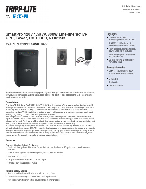
SmartPro 120V 1.5kVA 980W Line-Interactive UPS, Tower, USB, DB9, 6 OutletsMODEL NUMBER:SMART1500Protects connected mission-critical equipment against damage, downtime and data loss due to blackouts, brownouts, power surges and line noise. Ideal solution for point-of-sale applications, VoIP systems and small business networks.DescriptionThe SMART1500 SmartPro® 120V 1.5kVA 980W Line-Interactive UPS provides battery backup and AC power protection against blackouts, brownouts, power surges and line noise that can damage electronics or destroy data. Ideal for backing up point-of-sale applications, VoIP systems and small business networks, the SMART1500 switches to battery mode in milliseconds to keep your connected equipment running long enough to shut down safely with no data loss.Featuring six NEMA 5-15R outlets (one switchable) and a six-foot power cord with 120V NEMA 5-15P input, the SMART1500 has an internal battery that provides 20 minutes of support at half load and seven minutes at full load. Front-panel LEDs indicate line power, battery power, overload, voltage regulation and battery status. An alarm sounds to indicate power failure, overload or a low battery.Automatic voltage regulation (AVR) maintains 120V nominal output over an input range of 75V to 147V without using battery power. EMI/RFI noise filtering improves your equipment’s performance and prevents damage. A 480-joule surge suppression rating protects your equipment from harmful power surges. With PowerAlert® software (available via free download), the SMART1500 enables safe unattended system shutdown and file saves in case of a prolonged power failure.FeaturesProtects Mission-Critical EquipmentProvides fully regulated AC output for point-of-sale applications, VoIP systems and small business networksqAudible alarm signals loss of utility power, overload or low batteryq6 NEMA 5-15R outletsq6 ft. power cord with 120V NEMA 5-15P inputq480-joule surge suppression ratingqReliable Battery BackupSupports half load up to 20 min. and full load up to 7 min.qInternal batteries designed for hot-swap field replacementq96% line-power efficiency rating saves money in energy costsq HighlightsCorrects under- andovervoltages from 75V to 147V q6 NEMA 5-15R outlets—1switchable via network interface qFront-panel LEDs indicate load, power and battery statusesqMonitoring of power conditionsvia PowerAlert®q20 min. runtime at half load; 7min. at full loadqPackage IncludesSMART1500 SmartPro 120V1.5kVA 980W Line-InteractiveUPSqUSB cableqDB9 cableqOwner’s manualqSpecificationsCold-start capability enables turn-on in battery mode during blackoutsqLoad Bank with Switchable OutletCan control one outlet remotely to reboot equipment or shed nonessential loadsq Automatic Voltage Regulation (AVR)Maintains 120V nominal output over input range of 75V–147V without using battery powerq EMI/RFI Line Noise FilteringRemoves electromagnetic and radio frequency interference that can disrupt or damage equipment’s performanceq LED IndicatorsFront-panel LEDs indicate line power, battery power, overload, voltage regulation and battery statusq Communications PortsUSB & Serial ports enable data-saving unattended shutdown when used with PowerAlert software,available via FREE download from /products/power-alertq Small-Footprint Tower HousingMounts on wall with optional UPSWM accessoryq© 2023 Eaton. All Rights Reserved. Eaton is a registered trademark. All other trademarks are the property of their respective owners.。
IDEALARC AC1500操作手册说明书
Operator’s ManualSave for future reference Date PurchasedCode: (ex: 10859)Serial: (ex: U1060512345)For use with machines having Code Numbers: 11418Register your machine:/registerAuthorized Service and Distributor Locator: /locatorvvfor selecting a QUALITY product by Lincoln Electric. We want you to take pride in operating this Lincoln Electric Company product ••• as much pride as we have in bringing this product to you!PageInstallation.......................................................................................................................Section A Technical Specifications.......................................................................................................A-1 Location ...............................................................................................................................A-2 Input Wiring..........................................................................................................................A-2 Output Connections..............................................................................................................A-2 Wire Feeder Connections.............................................................................................A-2 Connection of AC-1500 to NA-4 with Switch for ʻCurrent Controlʼ.......................................A-3 Connection of AC-1500 to NA-4 with rheostat for current control or LT-6............................A-3 Output Studs................................................................................................................A-4Auxiliary Power............................................................................................................A-4 Duty Cycle............................................................................................................................A-4________________________________________________________________________________Operation.........................................................................................................................Section B Safety Precautions and Graphic Symbols..............................................................B-1 Product Design Application..................................................................................................B-2 Setting the Machine or Remote Control...............................................................................B-2 Setting the Output Current...................................................................................................B-2 Weld with Manual Electrodes...............................................................................................B-2 Product Description.......................................................................................................B-2,B-3 ________________________________________________________________________________Accessories.....................................................................................................Section C Optional Kit............................................................................................................C-1 Maintenance....................................................................................................Section D Safety Precautions................................................................................................D-1 ________________________________________________________________________Troubleshooting..............................................................................................Section E Safety Precautions.................................................................................................E-1 How to Use Troubleshooting Guide.......................................................................E-1 Troubleshooting Guide....................................................................................E-2,E-3 ________________________________________________________________________ Wiring Diagrams and Dimension Print..........................................................Section F ________________________________________________________________________Parts Pages.................................................................................P-556, P-28, P-84 Series ________________________________________________________________________vivi TABLE OF CONTENTSTECHNICAL SPECIFICATIONS - IDEALARC®AC-1500* Thomas & Betts wire terminals (or equal) recommended above are required to comply with applicable U.L. standards for safety. A #30 hex (Allen) key wrench is required for assembly of terminals to wire. Based on National Electrical Code - 100% Duty Cycle 40˚C (104˚F) Ambient.RATING: IP21 ENCLOSURE, INSULATION 155°(F)Connection of AC-1500 to NA-4S-15667with Switch for ‘Current Control’6-18-76AConnection of AC-1500 to NA-4with rheostat for current control.S-156026-22-84HOUTPUT STUDSConnect the work cables to the ʻTo Workʼ stud on the front of the AC-1500. Connect the electrode cables to the ʻMin,ʼʻMedʼ or ʻMaxʼ studs for the output desired.Actual current ranges for each stud are indicated on the nameplate above each stud. Recommended cable sizes are listed below. Both the ʻTo Workʼ and ʻMaxʼ studs have two terminals to simplify connection of recommend-ed cables in parallel. Tighten the nuts with a wrench.Select cables required for combined work and electrode cable lengths up to 150ʼ from the following table:Maximum Allowable Current for Copper Welding CableDutyCycle One 4/0Two 4/0Four 4/0Five 4/0100%650100012001500Cables in accessory kit recommended below have termi-nals as required to comply with applicable U.L. stan-dards for safety.150ʼ combined length electrode and work cables. AUXILIARY POWER1000 volt-amperes of 115 volt AC power are available from #31 and #32 on the AC-1500 terminal strip.D U TY C YC LEThe AC-1500 is rated for 100% duty cycle at 1500 amps and 44 volts.PRODUCT DESCRIPTION Array Specifications are 50 Hz, 380 volt unit with a Power factor correction as a standard feature.Output terminals, control power terminal strip, and controls are recessed or hinged covered to affect a "dead front". Due to the excessive amount of stray magnetic flux developed by the saturable reactor, the center sections of the welder side panels are made of a high impact, self-extinguishing, chemical resistant plastic material. USE OF METALLIC PANELS IN THEIR PLACE WILL RESULT IN EXCESSIVE HEAT-ING OF THE PANELS AS WELL AS THE SHEET METAL SCREWS USED IN THE ASSEMBLY OF OTHER CASE PARTS.Output welding current is available in three overlap-ping ranges by means of externally connecting the electrode cables to the Min., Med., or Max. tap elec-trode studs(See Technical Specifications in the Installation Section).Input Line Voltage Compensation maintains a rea-sonably constant output within a range of ±10% change in supply line voltage.Cooling of the welder is accomplished by drawing air in through the louvered case front panel, through the reactor and transformer assemblies, and out the lou-vered case rear panel. The two totally enclosed fan motors used have sealed ball bearings and require no lubrication maintenance.Handling of the welder and any attached devices should be done with a fork-lift or pallet-jack capable of loads exceeding the combined weight of the system. Overload/Thermal Protection is provided in three areas: the 115 volt AC auxiliary power is fused for 8 amps; the saturable reactor control power circuit is protected by a 40 amp fuse; the welder output power circuit is protected by the familiar current transformer-Klixon thermostat breaker. In the event of a control cir-cuit or welder overload, the output contactors will open and the fan motors will continue to operate. If the overload is detected by the thermostatic breaker, the temperature light located on the front panel will illuminate until a safe operating temperature is reached.Output Contactor control is provided by two S78 contactors connected in parallel. Input line contactors are not provided. The customer is expected to provideline starting and circuit breaking equipment.Pilot light indicates when the supply lines to the welder are electrically "hot". This means that the welder input power and control transformers are ener-gized when the pilot light is on.Input Circuit Plan:The AC-1500 is not intended for the connection of flexible supply cables. Instead, the following table may be used for planning of supply cables routed in conduit (See Technical Specifications in the Installation Section).Starting Device:The pushbuttons located on the front panel are not connected to any kind of starting or stopping device. They are not necessary to operating the welder. If pushbutton operation is desired, an input contactor must be professionally installed and wired to the pushbutton assembly. The AC-1500 does not have an input contactor. Therefore, include an exter-nal starter or disconnect switch when planning the input circuit. Once the input circuit is energized, the pilot light on the front panel should glow. High voltage is present inside the machine. Do not open the machine enclosure.Input Panel is made accessible by removal of the right side panel assembly (as viewed from front). Supply lines and grounding lead should be brought into the welder through the hole provided in the case rear panel. Connections to the input panel should be made as instructed on the wiring diagram attached to the welder. The grounding lead connection is to be made to the grounding stud provided on the welder base directly below the input panel.Location of installation should be such that the welder cooling air exhaust area (the case rear panel) is free of any obstructions that could impede air flow.A dry location should be chosen. The welder should not be placed on a surface that is inclined enough that it creates a risk of the machine falling overControl Circuit connections for wire feeder equip-ment are to be made per instructions on the wire feed-er diagram to the terminal strip provided under the hinged cover on the case front panel of the welding power supply. A strain relief strap to the right of the terminal strip is provided for attaching either the feed-er control and remote current control cables or both simultaneously. A grounding screw located just to the right of the terminal strip is provided for connecting the wire feeder grounding lead. All connections must be made with the welding power supply turned off.Hand Welding with stick electrode or semiautomatic arc welding is not recommended since OCV exceeds the 80 volts RMS limit allowed by standards for such use. (Unit is within 100 volt allowable limit for auto-matic or mechanically guided welding.)Scott Connection information for tandem arc applica-tion and paralleling of Scott connected units for tan-dem arc application is available. (See list of wiring diagrams.)I solated Auxiliary Power of 1000 volt.-amp., 115 volts AC is available at terminals #31 and #32 on the terminal strip under the hinged cover on the case front panel of the welder. The circuit is fused with an 8 amp slow blow fuse located in the nameplated section of the welder front panel.OPTIONAL KIT:Remote control K775.This Troubleshooting Guide is provided to help you locate and repair possible machine malfunctions.Simply follow the three-step procedure listed below.Step 1.LOCATE PROBLEM (SYMPTOM).Look under the column labeled “PROBLEM (SYMP-TOMS)”. This column describes possible symptoms that the machine may exhibit. Find the listing that best describes the symptom that the machine is exhibiting.Step 2.POSSIBLE CAUSE.The second column labeled “POSSIBLE CAUSE” lists the obvious external possibilities that may contribute to the machine symptom.Step 3.RECOMMENDED COURSE OF ACTIONThis column provides a course of action for the Possible Cause, generally it states to contact your local Lincoln Authorized Field Service Facility.If you do not understand or are unable to perform the Recommended Course of Action safely, contact your local Lincoln Authorized Field Service Facility.HOW TO USE TROUBLESHOOTING GUIDEService and Repair should only be performed by Lincoln Electric Factory Trained Personnel.Unauthorized repairs performed on this equipment may result in danger to the technician and machine operator and will invalidate your factory warranty. For your safety and to avoid Electrical Shock, please observe all safety notes and precautions detailed throughout this manual.__________________________________________________________________________AC-1500 SCOTT CONNECTION DIAGRAMAC-1500 SCOTT CONNECTION DIAGRAMM14364 4-8-83EAC-1500 AND DC-1500’s18.7422.3053.5036.1220.0038.003.69.406 D I A .M T G . H O L E SS -157094-18-75BJapaneseChineseKoreanArabicREAD AND UNDERSTAND THE MANUFACTURER’S INSTRUCTION FOR THIS EQUIPMENT AND THE CONSUMABLES TO BE USED AND FOLLOW YOUR EMPLOYER’S SAFETY PRACTICES.SE RECOMIENDA LEER Y ENTENDER LAS INSTRUCCIONES DEL FABRICANTE PARA EL USO DE ESTE EQUIPO Y LOS CONSUMIBLES QUE VA A UTILIZAR, SIGA LAS MEDIDAS DE SEGURIDAD DE SU SUPERVISOR.LISEZ ET COMPRENEZ LES INSTRUCTIONS DU FABRICANT EN CE QUI REGARDE CET EQUIPMENT ET LES PRODUITS A ETRE EMPLOYES ET SUIVEZ LES PROCEDURES DE SECURITE DE VOTRE EMPLOYEUR.LESEN SIE UND BEFOLGEN SIE DIE BETRIEBSANLEITUNG DER ANLAGE UND DEN ELEKTRO-DENEINSATZ DES HERSTELLERS. DIE UNFALLVERHÜTUNGSVORSCHRIFTEN DES ARBEITGEBERS SIND EBENFALLS ZU BEACHTEN.JapaneseChineseKoreanArabicLEIA E COMPREENDA AS INSTRUÇÕES DO FABRICANTE PARA ESTE EQUIPAMENTO E AS PARTES DE USO, E SIGA AS PRÁTICAS DE SEGURANÇA DO EMPREGADOR.。
Firemaster FP1500灌水淋浇工具说明书

Available Accessories Artillery Nozzle Kit (PN 121840AR) Cavalry Nozzle Kit (PN 121840CA)Cone Safety Red 18” tall (PN OBJ-714) Fill Hose 25’ (PN J-2439) Footpedal Transmitter IntelAControl® (PN OBJ-2530FT)Grit Catcher 6” (PN OB00016A) Grit Catcher 8” (PN OB00018A)Hand Held Transmitter IntelAControl® (PN OBJ-2530HT)Infantry Nozzle Kit (PN 121840IN) Kit -Emergency Hand Crank (PN OBJ-300) Manhole Cover Hook (PN 015-438) Nozzle Extension - Finned 1/2” (PN J-40-7) Nozzle Extension - NonFinned 1/2” (PN J-40-3) Root Cutter Kit (PN OBJ-1467) Rotating Beacon - Magnetic Mount (PN RL650A) Strobe Light - Magnetic Mount (PN SL650A) Tiger Tail - 2" x 36" (PN J-2204) Tiger Tail - 3” x 36” (PN J-2203)Tiger Tail - 3” x 42” (PN J-2205)The Ultimate WorkhorseWith a water tank that doubles the capacity of any smaller trailer unit and a powerful engine/pumpcombination, this model efficiently tackles a wide range of line cleaning duties all the way up to 24” mains. The rigid chassis and axle design give it stability, so you can haul a full tank of water at highway speeds. Standard unit color is safety yellow or white -customer choice. Can be custom painted to match almost any color, for an additional charge.“Swinger” Reel—190°PivotMakes line cleaning a simple job because it allows for:•Easy access to the manhole regardlessof how trailer is parked •Tethered hand control •Variable-speed control •Hydraulic driven •‘Catwalk’ fenders350 Gallon Polyethylene T ankPlate mounted with sump and side baffles Crowned top & side stabilizers for addedstrengthSufficient water supply for necessary water flow12” Manhole with basketHigh-Impact Thermoplastic Sewer HoseEasy to keep clean (retains no bacteria-causing residue).Maintains stiffness and is abrasion resistant.Standard 400’ of 1/2”hose reaches from manhole to manhole.Reel capacity is 1,000’ of 1/2” hose. Cummins Diesel Engine 65hpMurphy safety gauges with auto -shutdown Variable electronic throttle control 18GPM@4,000PSI Pump•Triplex pump Single-Axle Trailer The Trailer Jetter is rated to carry a full tank of water to the job . . .•6” channel frame•A-frame hitch •25-5/16” ball hitch•7,000 lb. DOT-rated axle •ST-235 x 85R16 tires •Electric brakesOther Standard Components •Two nozzles: penetrator & flusher •PVC tank drain valve with stainless steel strainer •Direct driven “live” hydraulic system with 17-gallon tank•17-gallon fuel tank with cap-mounted gauge.•Air purge system•20' Leader hose contrasting color •Two (2) aux 12V power supply outlets •2” PVC fill pipe •Level Wind Guide Standard Components$30,695.00Price includes Delivery/TrainingSignature: _______________________Printed Name: ____________________Date: __________PRICE: Alternate Price With Steel Shroud: $38,606.00h Prices and features subject to change . without notice. Quantities may beTrailer JetterAvailable Options 100’ 1/2” Extra Hose on Main Reel (PN OBJ-100-12AH)200’ 1/2” Extra Hose on Main Reel (PN OBJ-200-12AH)Anti-Freeze System (PN OBJ-234) Arrow Board (PN OBJ-144) Auto Level Wind Guide Mounted (PN OBJ-9032) Cone Holder Only (PN OBJ-137) Custom Decals (two) 73HP Kubota Diesel Engine (PN OBJ-73KO) 80HP JohnDeere Diesel Engine (PN OBJ-80JDO)85HP Cummins Diesel Engine (PN OBJ-85CO)E-Stop Assembly (PN IC-100405-01)Foot Control Swinger (PN OBJ-187A) Garden Hose Reel 1/2” - 50’ (PN OBJ-123000L) Garden Hose Reel Electric 100’ (PN OBJ-294) Garden Hose Reel Manual 100’ COX (PN OBJ-293) Hydraulic Surge Brakes (PN 3500SB) IntelAControl® Complete Package (P N OBJ-530CP)IntelACount® (PN OBJ-2430E)Low Water Shutdown (PN OBJ-2424)Level Wind Guide w/Counter (PN OBJ-2430A)Paint Custom (Paint Code Required) (PN P AINT -CUSTOM)STDP aint - Safety Yellow (PN PAINT-1Y)STD P aint - White Enamel (PN PAINT-3W)P intle Hitch (PN OBJ-1081P)Pulsator LP301A (PN 22737)Recirculation System (PN OBJ-1/2"RECIRC ) Rotating Beacon-Fixed (PN OBJ-241B ) Side Panels (two) - Painted (PN OBJ-2523P) Spare Tire Holder w/Tire 16” (PN OBJ-9060-700016) Tank Shroud Aluminum (PN 3500ADS) Tank Shroud Steel (PN 3500SS) Wireless Remote (PN OBJ-101)Tire & Rim 16” Spare 8 lug (PN J-700-19) Upstream Pulley Guide (PN J-2401) Washdown Gun w/Hose (PN 15007-B) Wireless Repeater IntelAControl®(PN OBJ-2530WR) Work Light - Magnetic Mount (PN OBJ-500R)3518-SC CORPORATE HEADQUARTERS4713 Gettysburg Rd | Mechanicsburg, PA 17055。
R1500激光测距仪使用说明书
R1500|1200米激光测距仪使用说明书目次1 用途 (1)2 主要性能及技术规格 (2)3 镜内符号及功能 (2)4 测距操作 (3)5 使用注意事项 (4)6 附件 (4)1 用途R1500激光测距仪是一种高级的激光测距系统,可以快速提供精确测量的距离。
其独特的光学性能可以在任何情况下提供清晰的图像。
该激光测距仪用的是最新的数字电路设计和光学系统,同时,在镜片质量和价格上是其他任何产品都无法超越的。
该测距仪具备高档望远镜和激光测距双重功能。
具有测距时间快、距离显示直观、测距精度高,耗电省,不使用时自动断电等特点。
该仪器体积小、外形美、重量轻,便于携带;机内使用一节9V电池,更换方便。
该测距仪广泛用于高尔夫球、打猎等体育、野外活动的距离测量;也广泛用于电杆、桥梁和建筑工地的距离测量;还可用于一般的地形测量、仓储测量等。
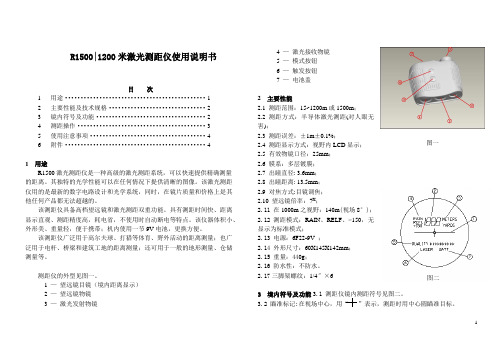
测距仪的外型见图一。
1 —望远镜目镜(境内距离显示)2 —望远镜物镜3 —激光发射物镜4 —激光接收物镜5 —模式按钮6 —触发按钮7 —电池盖2 主要性能2.1 测距范围:15~1200m或1500m;2.2 测距方式:半导体激光测距(对人眼无害);2.3 测距误差:±1m±0.1%;2.4 测距显示方式:视野内LCD显示;2.5 有效物镜口径:25mm;2.6 膜系:多层镀膜;2.7 出瞳直径:3.6mm;2.8 出瞳距离: 13.5mm;2.9 对焦方式:目镜调焦;2.10 望远镜倍率:7X;2.11 在1000m之视野:140m(视场8°);2.12 测距模式:RAIN、RELF、>150,无显示为标准模式;2.13 电源:6F22-9V;2.14 外形尺寸:60X145X142mm;2.15 重量:440g;2.16 防水性:不防水。
2.17三脚架螺纹:1/4″×63 境内符号及功能3.1 测距仪镜内测距符号见图二。
3.2 瞄准标记:在视场中心,用“”表示,测距时用中心圆瞄准目标。
AG-1500 抗菌氛围吹风机用户手册说明书

USER MANUAL- ENGLISHThank you for choosing Air Guard. Please read the following safety information carefullybefore operating the machine. This information includes important safeguards aboutinstallation, usage, and maintenance. Pay attention to all warning labels and instructionsin this manual and printed on the machine.l Keep this device dry.l Always connect to a grounded circuit to avoid risk of electrocution.l Before connecting the machine to power, always check the voltage indicate on the machine matches to your local AC voltage. Do not use the machine if AC power voltage does not match. l Disconnect the machine from AC power before servicing and when not in use.l If the supply cord is damaged, contact your local dealer for replacement.l This product is for indoor use only! Do not expose to rain or moisture. If fluid is spilled, disconnect AC power and clean with a damp cloth. If fluid is spilled onto electronic parts,immediately unplug the machine and contact your local dealer for advice.l No user serviceable and modifiable parts inside. Never try to repair this product, an unauthorized technician may lead the machine to damage or malfunction.l For adult use only. Children being supervised not to play with the machine. Never leave the machine running unattended.l The machine is not to be used by persons (including children) with reduced physical, sensory or mental capabilities, or lack of experience and knowledge.l Installed in a well ventilated area. Provide at least 50 cm space around the machine.l Never add flammable liquid of any kind to the machine.l Make sure there are no flammable materials close to the machine while operating.l Only use Air Guard Antibacterial Solution. Other solution may lead to heater clog and malfunction.l If the machine fails to work, unplug the machine and stop operation immediately. Contact your local dealer for advise .l Before transporting the machine, make sure the fluid tank is completely drained.l Air Guard Antibacterial Solution may present health risks if swallowed. Do not drink Air Guard solution. Store it securely. In case of eye contact or if solution is swallowed immediately look for medical advice.Immediately upon receiving the antibacterial vaporizer, carefully unpack the carton, check the content to ensure that all parts are present and have been received in good condition. If any parts appear damaged or mishandled from shipping, notify the shipper immediately and retain the packing material for inspection.What is included: 1 x AG-1500 Antibacterial Vaporizer1 x Wireless Remote Control1 x Power Cord1 x User ManualProduct DimensionsH 381 mmL 344 mmW 193 mmStep 4: Turn on the machine by connecting the power cord. Heat-up takes approximatley 6 minutes. Once the machine has reached operating temperature, the LCD screen will display “Ready To Fog”. LCD control panelWireless receiver (antenna) Power Switch Breaker Power InletFog Output NozzleControl Panel OperationSet output time 30, 60, 90, 120, 150 or 180 seconds Set output volume to normal or high Turn On/Off wireless controlOutput Time30 SecOutput VolumeNormalWirelessOffWireless remote control system W-1 consists of a transmitter equipped with two buttons to activate, deactivate and an onboard receiver attached to the rear panel of AG-1500.W-1 Wireless TransmitterPress [A] button to emit fog and press [B] button to stop.In an unobstructed open space the effective distance is 50 meters, usage depending on obstacle level the effective distance is 10-25 meters.Wireless ReceiverRegistering transmitterTransmitter can be paired or deleted from the receiver. Each receiver can pair up to 10 transmitters. Follow below steps to pair or delete transmitter from receiver.Step 1: Power off AG-1500 Antibacterial VaporizerStep 2: Press and hold [DOWN] buttonStep 3: Turn power on and release [DOWN] button when LCD display blinksStep 4: Follow the menu instruction to pair or delete transmitterNotes:One machine can be controlled by up to 10 transmitters while one transmiter can be paired with an unlimited number of machines.Transmitter battery replacementIf the effective distance seems to decrease, it is possible the battery level is low and requires replacement. In order to replace the battery, undo the three screws on the back of transmitter to release the cover. Replace with the same type and specification of battery which is 27A 12VUse Air Guard FLD / FLV Antibacterial Solution for AG-1500. Themachine is tested and calibrated with this fluid to achieve the bestoutput performance. Warranty will be voided if any other type ofliquid is used, improper use of liquid may lead to machine failure andmalfunction.․Do not allow the machine and fluid to become contaminated.․Regularly fill distilled water to fluid tank and run the machine to clean the system. After cleaning, refill Air Guard fluids into fluid tank and make sure machine can produce fogproperly.․It is recommended to run the machine on a monthly basis in order to achieve best performance and output condition.․Excessive dust, liquid and dirt built up will degrade performance and cause overheating. Breaker ResetDisconnect AC power before resetting the breaker. Only replace fuse with same typeand rating.Step 1: Disconnect AC power.Step 2: Flip breaker to ON position.Step 3: Turn on machine for testing.Breaker100-120V = 15A 250V220-240V = 8A 250V- Input voltage- Rated power- Warm-up time- Fluid consumption- Fluid tank capacity- Compatible fluid- Ambient temp. range- Output- Control- Connection- Dimension- Weight US model : AC 100-120V, 50 / 60Hz 12A EU model : AC 220-240V, 50 / 60Hz 6A 1450W 6 minutes (approx.) 40 ml/min 2.4L (0.63gal) Air Guard FLD Antibacterial Solution Air Guard FLV Antibacterial Solution 0 °C - 40 °C (32 °F-104 °F) 2 meters height Timer Wireless IEC (Power) L344 W193 H381 mm (L13.54 W7.60 H15 inch) 10.7 kg (23.6 lbs)M22 Moisture Co., Ltd.Tel : +886 3 2227470 Fax : +886 3 2227469 e-mail : ******************.twC08AG1500。
