[整理]DCSSU-25操作手册
DCS操作说明资料
DCS操作说明资料DCS(Distributed Control System,分布式控制系统)是一种广泛应用于工业控制领域的自动化控制系统。
它能够集中控制多个分散的控制单元,通过数据通信实现对工业过程的监控与操作。
下面是一份DCS操作说明的资料,详细介绍了DCS系统的配置、操作和故障处理等方面的内容。
一、DCS系统配置1.硬件配置1.1主控制器:负责控制整个DCS系统的主要模块,包括CPU、存储器和输入输出接口等。
1.2输入输出模块:用于接收和发送实时过程数据。
1.3通信网络:建立控制系统内部不同模块之间的通信连接。
1.4控制台:供操作人员进行监控和操作的界面。
2.软件配置2.1SCADA软件:用于数据采集与处理,实现对工业过程的监控和控制。
2.2PLC程序:编写用于控制工业过程的程序,与SCADA软件进行通信。
二、DCS系统操作1.登录系统输入用户名和密码,进入DCS系统。
2.监控界面2.1实时数据显示:显示工业过程的各种参数,如温度、压力等。
2.2图形界面:通过图形化方式展示工业过程的设备、管道等情况,便于操作人员理解。
3.控制操作3.1自动操作:按照预设的控制策略进行控制。
3.2手动操作:手动开关控制设备,进行临时控制。
3.3调整参数:根据工艺要求调整设备参数,如温度、压力设定值等。
4.报警管理4.1报警显示:当系统出现异常情况时,显示相应的报警信息。
4.2报警处理:针对不同的报警情况,进行相应的处理措施。
5.数据记录与分析5.1数据记录:对工业过程中的关键参数进行实时记录,生成数据记录。
5.2数据分析:对工艺过程中的数据进行分析,寻找潜在问题和改进机会。
三、DCS系统故障处理1.报警解除1.1确认报警情况:判断是真实报警还是误报警。
1.2解除报警:根据具体情况采取相应的解除措施。
2.故障排查2.1跟踪报警日志:查找故障发生的时间和原因。
2.2检查设备及传感器:确认设备和传感器是否正常工作。
Su-25T教程详解及说明
第 二 步 : 切 换 到 对 地 攻 击 模 式 [7] 。 用 [C] 键 选 择 内 部 机 枪 , 用 [Ctrl+Space]键选择机炮吊舱并且在 HUD 和 WCS 面板上确认。调整发射间距 /机炮吊场模式到修正“FIX”模式。发射数量切换到 PO2。
如果飞机有 4 个机炮吊舱,那么再多按以下[Ctrl+Space]。调整发射间 距/机炮吊场模式到修正“FIX”模式。发射数量切换到 PO2
KMGU-2 子母弹投放器需要将瞄准点移到目标上方,以便容器有时间打 开投放舱门。
C.非制导火箭及内部机炮: 非制导火箭包括所有每有装备制导系统的火箭以及导弹。他们包括 UB32 火箭发射器中的 S5,B8 火箭发射其中的 S8,以及 s24 和 s25。自带机炮包 括 30 毫米 GSh301。 1、 目视确定目标 2、 用[7]键选择对敌模式,同时用[D]键切换到非制导火箭武器,或者 按[c]选择机炮。同时在 HUD 上确认武器选择正确。然后手动操作飞机已小 攻角向目标俯冲。 3、 当目标瞄准环套在目标上并且进入发射距离后,“LA”的发射字样会
DCS操作员站操作说明
第三章DCS 系统操作员站操作规程3.1操作员站的登录和退出机组正常运行时,禁止任何人随意退出和登录操作员站。
3.1.1操作员站的登录除了大小修和特殊情况外,操作员站应该不存在登录问题,即在正常运行过程中不会发生登录的情况。
在大小修和特殊情况时,运行人员登录操作员站,需要在热控人员的指导下,由值长同意,运行人员方可以分配给相应的运行人员的用户名和密码登录,禁止使用和自己职责不相符的用户名和密码登录。
运行人员有权保护自己的用户名和密码。
登录窗口位于屏幕主菜单的“工程师功能”的“登录”项,单击鼠标左键即可出现登录窗口。
写入相应登录级别的用户名、口令、域号,单击“登录”按钮确认,即进入相应的级别。
3.1.2操作员站的退出除了大小修和特殊情况外,禁止任何人随意退出操作员站。
在大小修和特殊情况时,运行人员退出操作员站,需要在热控人员的指导下,由值长或主值同意。
退出窗口位于屏幕主菜单的“系统功能”的“退出”项,单击鼠标左键即可出现退出窗口。
输入“退出密码”,即可退出操作员在线系统。
3.2操作员站画面操作指导3.2.1操作员站总体画面操作介绍3.2.1.1功能区说明:在操作员监视屏幕上显示运行画面,监视屏幕可划分为9个区。
3.2.1.1.1I 区:工具栏菜单区。
用鼠标单击其中的图标按钮,可弹出相应的功能菜单。
3.2.1.1.1.1向前翻页快捷图标:此按键具有记忆功能,可以按顺序记忆打开的所有画面,点击此图标可按图形的先后顺序进行图形文件的显示切换,在当前窗口中显示前一幅流程图。
3.2.1.1.1.2历史页快捷图标:此按键具有记忆功能,可以按顺序记忆打开的所有画面,点击此图标可选择打开已浏览过的任一幅流程图。
3.2.1.1.1.3向后翻页快捷图标:此按键具有记忆功能,可以按顺序记忆打开的所有画面,点击此图标可按图形的先后顺序进行图形文件的显示切换,在当前窗口中显示后一幅流程图。
3.2.1.1.1.4图形管理快捷图标:点击此图标将弹出“图形管理”功能菜单。
(整理)DCSSU-25操作手册.
LOCK ON中文讲解课程本章节主要讲解苏系战机起飞操作步骤飞机起飞步骤大体分为三个部分一:启动发动机二:滑出停机坪上跑道三:起飞首先是启动发动机的步骤,我们所实用的机型是SU-25T,只所以不是SU-27,是因为SU-27T是LOCK ON中操作步骤比较复杂的机型,它的启动步骤包含其他机型的启动步骤,同时也有所复杂,所以我们用SU-25T来讲解飞机的启动步骤现在我们在SU-25T的座舱里可以看到飞机的所以仪表都处在关闭状态,因为主电源是关闭状态,我们通过Shif+“R“键打开飞机的主电源,注意仪表开始有变化,观察气压高度计,我们通过Shif+“-“和Shif+“=“将气压高度计归零,这是SU-25T在LOCK ON中的标准操作步骤,至于为什么要将它归零,我也不知道!好,一切仪表正常,准备启动发动机,我们按Ctrl+“L“键点亮翼灯,向塔台表明我们要启动发动机,确认节流阀收到低按键盘右侧(空格右边第2个键)文斗丝间和HOME键,让发动机启动,注意发动机的转速表开始变化,发动机已经启动,SU-25T是双阀战斗机,目前版本的LOCKON当中的所有可用机型都是双阀,所以我们可以单独的启动左发动机和右发动机,通过按ATT GR+HOME键来来启动左发动机,通过Shif+HOME键来启动右发动机,目前版本的LOCKON中SU-25T以及SU-25的启动步骤是相同并且是最复杂的,其他大部分机型的启动步骤中,进入座舱后,电源本身是打开的,仪表也不需要矫正,直接启动发动机即可,现在我们回到SU-25T的座舱观察仪表,发动机及启动完全属于怠速状态,接下来我们需要滑出停机坪上跑道,如果我们对于存在的机场并不熟悉的话,并不清楚上跑道的路线,这时候我们可以通过键盘左边数字键(小键盘)的4号键和6号键左右旋转头部视角,观察机场寻找上跑道路线,当然有的时候由于距离或者角度的关系,左右观察也找不到上跑道的路线,这个时候我们可以通过按F2键切换到机外视角,用小键盘的(右边数字键)“/“键和“*“键切换视角的远近,按照机场远的距离能够看清整个机场,寻找上跑道路线。
DCS操作

FM171B模块介绍
• FM171B模块是智能型16路晶体管开关量 输出模块,是和利时公司采用的现场总线 技术而新开发的DO信号输出模块。 FM171B模块作为Profibus-DP的从站通过 Profibus-DP总线把采集到的信号及相关诊 断信息上传到Profibus-DP主站。它是智能 型现场总线产品,能够与其他公司系统相 连,也是构成和利时MACiAS-MACS系统结构
• • • HOLLiAS-MACS系统由上下两个网络层次组成:监控网络和控制网络。 上层监控网络主要用于工程师站、操作员站和现场控制站的通讯连接。 下次控制网络存在于各个现场控制站内部,主要作用于主控单元和智能I/O单元的通讯连接。
• 监控网络
–
–
现场监控网络为冗余高速以太网链路,使用五类屏蔽双绞线及光纤将各个通讯节点连接到中心交换机上。该 网络中主要的通讯节点有工程师站、操作员站、现场控制站,采用TCP/IP通讯协议,不仅可以提供100Mbps 的数据连接,还可连接到Internet,进行数据共享。 监控网络实现了工程师站、操作员站、现场控制站之间的数据通讯。通过监控网络,工程师站可以把控制算 法程序下装到现场控制站的主控单元上,同时工程师站和操作员站也可以从主控单元上采集实时数据,用于 人机界面上数据的显示。
使用模块
FM148A模块介绍
• FM148A模块与配套的段子底座FM131A连 接,形成了一个完整的智能I/O单元。它的 适用范围广,可以接受二进制电流设备的 电流信号,也能接受四线制电流设备的电 流信号,还能够接受电压信号。当所采集 的模拟量信号类型产生变化时,不需要在 模块内部进行任何设置,只改变信号线在 段子底座FM131A的接线方式,因此它在使 用中方便灵活。
su25t飞行手册
su25t飞行手册
摘要:
一、SU-25T飞行手册简介
1.SU-25T的背景和历史
2.飞行手册的目的和适用对象
二、飞行手册的主要内容
1.飞行手册的结构和章节划分
2.各章节的主要内容概述
三、飞行手册的使用方法
1.阅读和理解飞行手册的顺序
2.飞行前需要完成的准备工作
3.飞行中需要遵循的操作步骤
四、飞行手册的重要性和作用
1.保证飞行安全和任务成功的重要工具
2.帮助飞行员了解飞机性能和操作限制
3.提高飞行员的操作技能和应变能力
正文:
SU-25T飞行手册是一本为SU-25T战斗机飞行员提供操作指南和飞行技巧的书籍。
SU-25T是苏联/俄罗斯一型单座双发全天候低空攻击战斗机,主要用于近距离空中支援和战场遮断任务。
飞行手册分为若干章节,包括飞机概述、飞行特性、飞行性能、武器系
统、导航设备、飞行规则和程序等。
飞行员需要熟悉和掌握这些内容,以确保飞行安全和任务成功。
阅读和理解飞行手册是飞行前的重要准备工作。
飞行员应按照飞行手册的顺序,逐步了解和掌握飞机的相关信息。
在飞行过程中,飞行员需要遵循飞行手册中提供的操作步骤和程序,以确保飞机的安全和稳定。
飞行手册对于飞行员来说具有非常重要的作用。
它不仅可以帮助飞行员了解飞机的性能和操作限制,还可以提高飞行员的操作技能和应变能力。
DCSSU-25操作手册-9页精选文档
LOCK ON中文讲解课程本章节主要讲解苏系战机起飞操作步骤飞机起飞步骤大体分为三个部分一:启动发动机二:滑出停机坪上跑道三:起飞首先是启动发动机的步骤,我们所实用的机型是SU-25T只所以不是SU-27是因为SU-27T是LOCK ON中操作步骤比较复杂的机型,它的启动步骤包含其他机型的启动步骤,同时也有所复杂,所以我们用SU-25T来讲解飞机的启动步骤现在我们在SU-25T的座舱里可以看到飞机的所以仪表都处在关闭状态,因为主电源是关闭状态,我们通过Shif+R“键打开飞机的主电源,注意仪表开始有变化,观察气压高度计,我们通过Shif+“和Shif+“将气压高度计归零,这是SU-25T在LOCK ON中的标准操作步骤,至于为什么要将它归零,我也不知道!好,一切仪表正常,准备启动发动机,我们按L“键点亮翼灯,向塔台表明我们要启动发动机,确认节流阀收到低按键盘右侧(空格右边第2个键)文斗丝间和HOME键,让发动机启动,注意发动机的转速表开始变化,发动机已经启动,SU-25T是双阀战斗机,目前版本的LOCKON当中的所有可用机型都是双阀,所以我们可以单独的启动左发动机和右发动机,通过按ATT GR+HOME键来来启动左发动机,通过Shif+HOME键来启动右发动机,目前版本的LOCKON中SU-25T以及SU-25的启动步骤是相同并且是最复杂的,其他大部分机型的启动步骤中,进入座舱后,电源本身是打开的,仪表也不需要矫正,直接启动发动机即可,现在我们回到SU-25T的座舱观察仪表,发动机及启动完全属于怠速状态,接下来我们需要滑出停机坪上跑道,如果我们对于存在的机场并不熟悉的话,并不清楚上跑道的路线,这时候我们可以通过键盘左边数字键(小键盘)的46号键左右旋转头部视角,观察机场寻找上跑道路线,当然有的时候由于距离或者角度的关系,左右观察也找不到上跑道的路线,这个时候我们可以通过按F2键切换到机外视角,用小键盘的(右边数字键)“键和““键切换视角的远近,按照机场远的距离能够看清整个机场,寻找上跑道路线。
【免费下载】DCS系统操作手册
DCS系统操作手册1、系统界面。
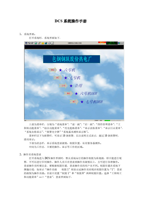
打开系统时,系统界面如下:上部为菜单栏,分别为“系统菜单”,“前一副”,“后一副”,“图形管理菜单”,“工程师功能菜单”,“综合功能菜单”,“历史趋势菜单”,“显示表格菜单”,“显示日志菜单”,“系统名称显示”,“报警光字牌”“系统基本属性显示框”。
菜单栏以下为报警栏,可显示10条报警,以点说明方式显示,超过10条报警时,滚动显示。
下部为状态栏,显示系统登录级别、权限位置,还有服务器属性。
中间为工作区,主要的操作、显示等工作的区域。
2、操作员系统登录打开系统进入DCS操作界面时,默认系统运行的操作权限为监视级,即只能进行观察,不可以进行任何操作,操作人员只有登录到操作员级别以上,方可进行各种操作。
登录操作员时要注意,要根据权限位置,登录操作员的用户名不同。
权限位置在系统下侧偏右端,如显示“操作员级权限1”则表示此操作员站现在权限位置为“1”,登录的级别为操作员级。
目前只设置“权限1”和“权限0”两种权限位置。
选择“工程师工程功能菜单”—>“登录”,登录界面如下:登录操作员时:,权限1对应的操作员登录的用户名为ops,没有密码。
权限0对应的操作员登录的用户名为ops0,没有密码。
登录到操作员后,可对系统进行基本操作,添加趋势,查看报警等。
3、趋势查询操作画面上有各种数据显示点,右键单击该点,选择点趋势,可查看该点的趋势画面。
注意:趋势画面是记录可以查看前推最近一次下装服务器到当前时间的点趋势。
点趋势画面如下:上侧,分别显示该点的点名,时间间隔。
时间间隔可以输入从1~60的整数,单位是秒,时间间隔是趋势曲线变化的时间率,即输入5秒,曲线5秒钟变化一次。
趋势曲线的状态可分为“跟踪”和“历史”两种状态,选择跟踪,曲线便根据时间间隔和实际数据变化而实时更新,选择历史则曲线不再变化,而点趋势画面下侧的“前推”和“后推”按钮可用,每推一次即翻一页。
趋势显示的方式分为“曲线”和“数字”两种,选择数字,则点的趋势以数据方式显示。
DCS系统操作手册
DCS系统操作手册1、系统界面。
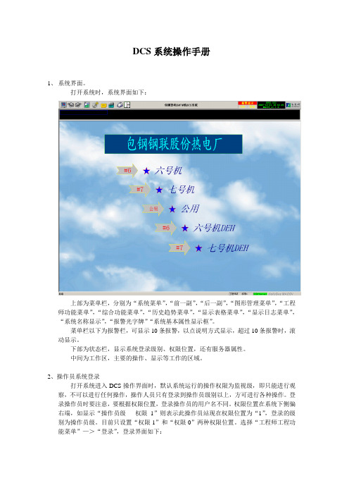
打开系统时,系统界面如下:上部为菜单栏,分别为“系统菜单”,“前一副”,“后一副”,“图形管理菜单”,“工程师功能菜单”,“综合功能菜单”,“历史趋势菜单”,“显示表格菜单”,“显示日志菜单”,“系统名称显示”,“报警光字牌”“系统基本属性显示框”。
菜单栏以下为报警栏,可显示10条报警,以点说明方式显示,超过10条报警时,滚动显示。
下部为状态栏,显示系统登录级别、权限位置,还有服务器属性。
中间为工作区,主要的操作、显示等工作的区域。
2、操作员系统登录打开系统进入DCS操作界面时,默认系统运行的操作权限为监视级,即只能进行观察,不可以进行任何操作,操作人员只有登录到操作员级别以上,方可进行各种操作。
登录操作员时要注意,要根据权限位置,登录操作员的用户名不同。
权限位置在系统下侧偏右端,如显示“操作员级权限1”则表示此操作员站现在权限位置为“1”,登录的级别为操作员级。
目前只设置“权限1”和“权限0”两种权限位置。
选择“工程师工程功能菜单”—>“登录”,登录界面如下:登录操作员时:,权限1对应的操作员登录的用户名为ops,没有密码。
权限0对应的操作员登录的用户名为ops0,没有密码。
登录到操作员后,可对系统进行基本操作,添加趋势,查看报警等。
3、趋势查询操作画面上有各种数据显示点,右键单击该点,选择点趋势,可查看该点的趋势画面。
注意:趋势画面是记录可以查看前推最近一次下装服务器到当前时间的点趋势。
点趋势画面如下:上侧,分别显示该点的点名,时间间隔。
时间间隔可以输入从1~60的整数,单位是秒,时间间隔是趋势曲线变化的时间率,即输入5秒,曲线5秒钟变化一次。
趋势曲线的状态可分为“跟踪”和“历史”两种状态,选择跟踪,曲线便根据时间间隔和实际数据变化而实时更新,选择历史则曲线不再变化,而点趋势画面下侧的“前推”和“后推”按钮可用,每推一次即翻一页。
趋势显示的方式分为“曲线”和“数字”两种,选择数字,则点的趋势以数据方式显示。
DCS World Su-25T Flight Manual EN

[SU-25T FROGFOOT]DCSDCS World Su-25TEagle Dynamics iFlight Manual[Su-25T Frogfoot]DCS World Su-25T is a free-to-play PC game. It includes the Su-25T attack aircraft with missions and a campaign. It is also the base for installation of the payware add-ons (modules) like DCS: A-10C Warthog or DCS: P-51D Mustang.General discussion forum in English: http://forums.eagle.ru/[Su-25T Frogfoot]Table of ContentsAIRCRAFT INTRODUCTION (1)S U-25ТF ROGFOOT (1)GAME AVIONICS MODE (3)N AVIGATION M ODE (5)A IR TO A IR M ODE (6)A IR TO G ROUND M ODE (7)SU-25T COCKPIT INSTRUMENTS (8)IAS – TAS Indicator (9)Configuration Indicator (9)AOA Indicator and Accelerometer (10)Attitude Direction Indicator (ADI) (10)Horizontal Situation Indicator (HSI) (11)Vertical Velocity Indicator (VVI) (11)Radar Altimeter (12)Tachometer (12)Fuel Quantity Indicator (13)Jet Engine Turbine Temperature Indicators (13)SPO-15 "Beryoza" Radar Warning Receiver (14)Weapon Status Panel (16)Weapon System Control Panel (17)Autopilot (ACS) Panel (18)O PERATIONAL M ODES OF THE S U-25ТHUD AND TV I NDICATORS (21)Basic HUD Symbology (21)Navigation Mode (22)Фи0 (Fi0) - Longitudinal Aiming Close Air Combat Mode (23)"Air-to-Surface" Weapon Mode (25)Precision Strike (28)Fixed Reticle Sight (35)RADIO COMMUNICATIONS AND MESSAGES (36)R ADIO C OMMANDS (36)R ADIO M ESSAGES (40)V OICE M ESSAGES AND W ARNINGS (42)SU-25T ADVANCED FLIGHT DYNAMICS MODEL (44)Cold Engine Start Procedure From the Parking Ramp (46)Eagle Dynamics[Su-25T Frogfoot]In-Air Automatic engine start (46)S PECIAL C ONSIDERATIONS FOR F LYING THE S U-25T (47)Taxi (47)Take-off (47)Crosswind Take-off (47)Landing (47)Crosswind Landing (48)Common Landing Errors (48)Stalls and Spins (48)WEAPONS DELIVERY (50)A IR-TO-A IR W EAPONS (50)R-73 and R-60 short range missiles (50)Internal Gun and Gun Pods Application Against Air Targets (51)A IR-TO-G ROUND W EAPONS (51)Unguided, Low-Drag Bombs (51)Unguided, High-Drag Bombs (52)TV Targeting Aided Bombing (52)Unguided Rockets and Internal Gun (53)Gun Pods (54)TV-Guided Bombs and Missiles (55)Laser Designation Missiles (56)Laser Beam-Riding Missiles (58)Antiradar Missile Delivery (60)SUPPLEMENTS (62)A ERODROME ID S (62)A CRONYM L IST (63)[Su-25T Frogfoot]Eagle Dynamics 1AIRCRAFT INTRODUCTIONSu-25Т FrogfootThe Su-25 has limited capabilities to search for and attack moving, small-sized armored units. After its introduction, it was clear that there was a need for creating a specialized anti-tank aircraft. In1976, the USSR Council of Ministers issued authorization for the commencement of the design andconstruction of an all-weather attack aircraft with anti-tank weapons.The primary anti-tank guided missile (ATGM) system for the Su-25T is the "Vikhr". This was later followed by the "Vikhr-M" with laser guidance. The primary aiming system, "Shkval", providesacquisition and automatic target guidance. This works in conjunction with the "Prichal" system that provides laser illumination and rangefinder.For low-light operations, the aircraft can be equipped with a fuselage-mounted pod with a low-level television camera. This system is termed "Mercury." "Mercury" provides an electro-optical aiming system to "Shkval" for night-time operations.Figure 1: Su-25TThe television image from the aiming systems is transferred to the IT-23M television monitor (TVM), which is positioned in the upper right portion of the instrument panel. "Shkval" provides a 23-fold[Su-25T Frogfoot]2target magnification, "Mercury" – provides a five-fold level of magnification. This helps identifying distant targets: a house – 15 km, a tank – 8-10 km, a helicopter like an "Apache" – 6 km.The integrated Electronic Warfare (EW) system provides detection and direction finding of air,ground, and naval radar emitters, with an accuracy of +/- 30 degrees in azimuth. The EW system can detect and classify radars emitting in the 1.2-18 GHz bands. Adjustable, Electronic Attack (EA)jamming can be used to reduce the effectiveness of weapon control radars operating in continuous wave and pulse modes. EA pods can be fixed to under-wing suspension hard points. For protection against infrared-guided missiles, expendable flares are used. The Su-25T is equipped with 192 flare cartridges. Also for protection against infrared-guided missiles, the electro-optical jamming system "Sukhogruz" is installed in the tail section of the aircraft. This powerful cesium lamp with an energy consumption of 6 kW creates an amplitude-modulated jamming signal that prevents infrared-guided missiles from guiding.To engage air defense radars, the Su-25T can be equipped with the "Viyuga" or "Phantasmagoria" target designation pods. This allows the Su-25T to designate targets for anti-radar missiles such as the Kh-58 and Kh-25MPU.Although the Su-25T is much improved from the standard Su-25 in regards to its weapon delivery capabilities, its flight performance has taken a step back. The added weight in particular has given the Su-25T poor performance and handling. The Su-25T is a powerful weapon platform, but it takes a skilled pilot to fly it well.When flying the Su-25T in DCS World, it is suggested that you set your input controls for pitch, roll and rudder to linear axis. This will provide the most realistic control of the aircraft.[Su-25T Frogfoot]Eagle Dynamics 3GAME AVIONICS MODEThe Game Avionics Mode provides "arcade-style" avionics that make the game more accessible andfamiliar to the casual gamer.This mode can be selected from the Gameplay Options tab or by setting the Game Presets to Game.Figure 2: Game Avionics Mode Radar DisplayThe display, located in the top right corner of the screen, is a top down view with your aircraft (green circle) located at the bottom center of the display. Symbols above your symbol are located in front of you, symbols to the right and left are located to the side of you.The images below illustrate the various features of the Game Avionics Mode. Note that you will see different symbols depending what mode the aircraft is in: Navigation, Air to Air or Air to Ground.Game Avionics Mode Radar Display[Su-25T Frogfoot]4 GAME AVIONICS MODEHowever, each mode will have the following data in common:∙Mode . Indicated outside of the top left corner of the display. This can show NAV (navigation), A2A (air to air) or A2G (air to ground). Mode keys:o Navigation: [1]o Air to Air: [2], [4] or [6] oAir to Ground: [7]∙Radar Range . Outside the top right of the display is the current range setting of the easy radar.Radar range keys:o Zoom in: [=] oZoom out: [-]∙ True Airspeed (TAS). Outside the lower left of the display is the true airspeed of your aircraft.∙ Radar Altitude . Outside the lower right of the display is the radar altimeter that indicates your altitude above the ground or water.∙Current Heading . Inside the display at the center top is your current aircraft magnetic heading.[Su-25T Frogfoot]Eagle Dynamics 5Navigation ModeFigure 3: Navigation ModeUnique symbols of the Navigation mode include:∙ (Player symbol). Your aircraft is indicated as a green circle at the bottom of the display. ∙ (Airfield symbol). This blue symbol indicates friendly airfields.∙ (Current waypoint symbol). This green circle indicates your current waypoint. You can cycle your waypoint with the [LCtrl - ~] (tilde) key.∙ (Waypoint symbol). This green triangle indicates other waypoints in your flight plan. ∙(Route line). Green route lines are connecting the waypoints in your flight plan.Navigation ModeCurrent Heading Friendly Airfield Current waypoint WaypointTrue AirspeedRadar RangeRoute linePlayerRadar Altitude[Su-25T Frogfoot]6 GAME AVIONICS MODEAir to Air ModeFigure 4: Air to Air ModeUnique symbols of the Air to Air mode include:∙ (Player symbol). Your aircraft is indicated as a green circle at the bottom of the display. ∙ (Friendly aircraft). All friendly aircraft are indicated as blue circles with lines coming from them that indicate flight direction.∙ (Enemy aircraft). All enemy aircraft are indicated as red circles with lines coming from them that indicate flight direction.∙ (Friendly missile). A friendly missile is indicated as a blue dot. ∙(Enemy missile). An enemy missile is indicated as a red dot.Useful key commands when in Air to Air mode include:∙ Auto Lock Center Aircraft: [RAlt - F6] ∙ Auto Lock Nearest Aircraft: [RAlt - F5] ∙ Auto Lock On Next Aircraft: [RAlt - F7] ∙Auto Lock Previous Aircraft: [RAlt - F8]Air to Air ModeCurrent HeadingFriendly missile Friendly aircraftTrue AirspeedRadar RangeEnemy aircraftPlayerRadar AltitudeEnemy missileEagle Dynamics 7Air to Ground ModeFigure 5: Air to Ground ModeUnique symbols of the Air to Ground mode include:∙ (Player symbol). Your aircraft is indicated as a green circle at the bottom of the display. ∙ (Friendly ground unit). All friendly ground units are indicated as blue squares. ∙ (Enemy ground unit). All enemy ground units are indicated as red squares.∙ (Friendly Air Defense Unit). A friendly air defense unit is indicated as a blue trapezoid with three lines coming from it.∙(Enemy Air Defense Unit). An enemy air defense unit is indicated as a red trapezoid with three lines coming from it.Useful key commands when in Air to Ground mode include:∙ Auto Lock Center Ground Target: [RAlt - F10] ∙ Auto Lock Nearest Ground Target: [RAlt - F9] ∙ Auto Lock On Next Ground Target: [RAlt - F11] ∙ Auto Lock Previous Ground Target: [RAlt - F12]Air to Ground ModeCurrent HeadingFriendly Air Defense UnitFriendly Ground UnitTrue AirspeedRadar Range Enemy Air Defense UnitPlayer Radar AltitudeEnemy Ground UnitFriendly AirfieldSU-25T COCKPIT INSTRUMENTSFigure 6: The Su-25Т Instrument Panelnding gear control lever2.Autopilot (ACS) control panel3.Angle of Attack (AOA) indicator and Accelerometer ("G meter")4.Airspeed indicator (IAS)5.Attitude direction indicator (ADI)6.Vertical velocity indicator (VVI)7.Tachometer (revolutions per minute or RPM)8.Fuel quantity indicator9."EKRAN" built-in test system display10.SPO-15 "Beryoza" radar warning receiver (RWR) panel13 2312158SU-25T COCKPIT INSTRUMENTS11.IТ-23М cathode ray tube (CRT) television (TV) display12.Aircraft clock13."Sukhogruz" infrared (IR) jammer indicator lamp14.Weapon system control panel (WCS)15.Flaps, slats, airbrake and landing gear configuration indicator16.Radar altimeter17.Barometric pressure altimeter18.Horizontal situation indicator (HSI)19.Neutral (takeoff) trim in pitch, roll and yaw indicator lamp20.Weapon status panel21.Engine temperature22.Hydraulic pressure meters23.Warning lampsIAS – TAS IndicatorThe IAS - TAS gauge indicates the aircraft’s True Air speed (TAS) in the interior of the gauge and Indicated Airspeed (IAS) in the outer portion of the gauge. The speed scale ranges from 0 to 1,100 km/h.TAS IASFigure 7: IAS-TAS IndicatorConfiguration IndicatorThe configuration indicator for mechanical devices shows the position of the landing gear, flaps, and airbrakes. If the landing gear is not successfully extended or retracted, a red lamp lights in the center of the indicator.Eagle Dynamics 910 SU-25T COCKPIT INSTRUMENTSFigure 8: Configuration IndicatorAOA Indicator and AccelerometerThe Angle of Attack (AoA) indicator and accelerometer displays the current angle of attack and G-load. The left part of the indicator shows the AoA in degrees, whilst the G-load is shown in the right part.Figure 9: AOA Indicator and AccelerometerAttitude Direction Indicator (ADI)The Attitude Direction (or Director) Indicator (ADI) shows the current angles of pitch and aircraft roll. In the lower part of the indicator is a slip indicator. Changing the rudder position eliminates slipping, so try to have the indicator in the central position. On the front portion of the indicator are the required bank and pitch indicators to reach the next waypoint. When both bars are in the central position, the aircraft is following the correct course. During landings, the W-shaped glide slope deviation indicator provides Instrument Landing System (ILS) direction.AirbrakesFlaps, maneuver positionFlaps, take-off and landing positionLanding gear warningLanding gearAoA indicatorG-loadEagle Dynamics 11Figure 10: Attitude Direction Indicator (ADI)Horizontal Situation Indicator (HSI)The Horizontal Situation Indicator (HSI) provides a top/down view of the aircraft in relation to the intended course. The compass rotates so that the current heading is always shown at the top. The Course Arrow shows the required heading and the Bearing Pointer points to the next waypoint. Distance to the next waypoint and required heading are shown numerically at the top. The ILS localizer and glide slope bars are in the center.Figure 11: Horizontal Situation Indicator (HSI)Vertical Velocity Indicator (VVI)The Vertical Velocity Indicator measures the aircraft’s vertical speed, i.e. rate of climb or sink. The Slip Indicator backs up the Slip Indicator on the ADI. The Turn Indicator shows the turn direction, though the rate of turn shown is only approximate.Required headingPitch scale Required bank Required altitude Required pitchAircraft datumBank scaleSlip indicatorCurrent HeadingDistance to waypoint Bearing pointerRequired headingILS barsDesired course arrowFigure 12: Vertical Velocity Indicator (VVI) Radar AltimeterThe radar altimeter indicates altitude above the ground from 0 to 1500 meters.Figure 13: Radar altimeterTachometerThe tachometer is intended for measuring rotor RPM of both engines. Measuring is indexed in percent from maximum rotor RPM.Turn indicatorVertical velocity indicatorSlip indicator12SU-25T COCKPIT INSTRUMENTSEagle Dynamics 13Figure 14: TachometerFuel Quantity IndicatorFuel quantity (P) shows the fuel remaining in all tanks. Fuel quantity (T) shows the fuel remaining in the feeder tank.If external fuel tanks are carried, a warning light indicates that they are nearing empty.Figure 15: Fuel Quantity IndicatorJet Engine Turbine Temperature IndicatorsThe two inter-stage turbine temperature indicators show the temperature of the exhaust gas from the left and right engine turbines.All tanks fuel quantityTank warningBingo (RTB required)Feeder tank fuel quantity14 SU-25T COCKPIT INSTRUMENTSFigure 16: Engine Temperature IndicatorSPO-15 "Beryoza" Radar Warning ReceiverThe RWR display indicates any threat radars illuminating ("painting") the aircraft. Information is presented as symbols representing the type and direction to the threat. Six illuminated symbols at the bottom of the display notify the pilot of the threat radar type. The system indicates both enemy and friendly radars.The system provides detection of radar signals at the following angles: Azimuth - +/- 180, and Elevation Range - +/- 30.The maximum number of threats on screen: Unlimited. The threat history display duration time: 8 seconds.Function modes: All (acquisition) or Lock (the "ОБЗОР/ОТКЛ" switch).Threat types:П – airborne radar З – long-range radar X – medium-range radar H – short-range radar F – early warning radar C–AWACS"Relative elevation" lights, "power of emission" gauge lights and "Lock/Launch" lights are only in regards to the primary threat.If the time between radar spikes of threat radar is eight or more seconds, the azimuth lights will not blink.In the case of an acquisition-type spike, the low frequency audio tone will sound.Eagle Dynamics 15If a radar is in lock mode, the "Lock/Launch" indicator will light up, along with a steady, high frequency audio tone.If a radar-guided missile launch is detected, the "Lock/Launch" light will flash, along with a high pitched audio tone.An ARH missile can be detected by the system after a missile establishes a lock using its own radar seeker. In this case, the missile will become the primary threat. The cue to recognize an ARH missile is the rapid increase in signal strength ("power of emission" lamps).Figure 17: "Beryoza" SPO-15LM indicatorThe ability to correctly interpret the information indicated on the RWS panel is vital in combat. As an example, let’s take a look at the situation shown in the picture above. As is seen in the picture, two threats are indicated on RWS panel:1.The primary threat at 50 degrees left (10 o’clock) is indicated in the form of a large yellow lamp. The lamp above "П" symbol, which means "interceptor", is lit. This type of threat includes all fighters. The circular scale of signal power ("light strip") consists of yellow segments that show the relative emission power of the primary threat’s radar. The large red circle under the aircraft symbol indicates that your aircraft has been locked by the primary threat radar. The lit, yellow hemispheres marked as "В" and "Н" in the center of the aircraft silhouette, indicate the threat’s relative altitude to yours. In this situation, the primary threat is at the same altitude as your own, within 15 degrees in elevation.Consequently, the display can be interpreted in the following way: your primary threat is aDirection to the primary threatOwn aircraft mark on the "light strip"Primary threat typeSecondary threat typePower light"Light strip" - Relative emission power of the primary threat, estimated range to threatRelative elevation of the primary threatRed flashing lamp - launch indicationDirection to the secondary threat16 SU-25T COCKPIT INSTRUMENTS fighter approaching from 10 o’clock; it is near co -altitude with you; and judging by the signal strength and lock light, it is ready to launch a missile. 2.The secondary threat is positioned at 10-30 degrees azimuth (1-2 o’clock right), and this is indicated by the two green lamps. The green "Х" symbol in the threat types line indicates that you're being targeted by a medium-range radar. There is no additional data on secondary threats.In a complex threat environment, it is often difficult to define the threat type and direction. In this case it is recommended to use the RWS mode filter [RShift-R] that removes all emitters operating in acquisition mode.The RWR can produce multiple audio alerts. You can adjust their volume by pressing [RAlt-,] – [RAlt-.] keys.Weapon Status PanelThe weapon status panel is located beneath the throttle handle in the left side cockpit instrument panel. The type, quantity and readiness of the currently selected weapon and the remaining gun ammunition are indicated.Figure 18: Weapon status panel∙The yellow lamps in the upper row indicate weapon availability and presence on hardpoint stations. When ordnance is launched or released, the corresponding yellow lamp goes dark.∙ The green lamps in the lower row indicate currently selected weapons that are ready for launch or release.∙The currently selected weapon type is indicated in the upper right of the panel: Б for bombs, УР for missiles, НРС for rockets,ВПУ for the built-in 30 mm cannon.∙The remaining cannon rounds are indicated in the lower right of the panel: К for full,1/2 for one-half, 1/4 for one-quarter.Weapon availabilityWeapons ready for useWeapon type indicatorGun rounds remaining (in quarters)Eagle Dynamics 17Weapon System Control PanelThe weapon system control panel can be seen near the bottom of the left instrument panel. Among other functions, this panel is used to control weapon salvo quantity [LCtrl-Space] and release interval [LShift-V] / [V].Figure 19: Su-25T Weapon System Control PanelThe weapon system control panel includes:∙ the release mode switch with positions ЗАЛП – 0.1 - 0.2 – 0.3 – 0.4 – СЕРИЯ КМГУ-МБД for free-fall ordnance, and 0 – ФИКС – ПРОГР for use with gunpods. ∙the salvo size switch with positions ПО 1 - ПО 2 – ПО 4 – ВСЕ.The release mode switch controls the manner in which air to ground weapons are employed:∙ ЗАЛП (SALVO) – all weapons in the salvo are released simultaneously.∙ 0.1 – 0.4 – individual weapons in the salvo are released with the selected interval (in seconds) between them.∙СЕРИЯ КМГУ-МБД (SSC-MJM SERIES) – a special release mode for the KMGU submunitions dispenser and multiple ejection rack (MER). KMGU submunitions are dispensed at 2-second intervals, MER munitions are released 0.3 seconds apart, according to the total quantity specified by the salvo size switch.∙ 0 – gunpods boresighted (aligned with aircraft longitudinal axis) for firing in a dive. ∙ ФИКС (FIX) – gunpods barrel depression set to a fixed value for strafing runs in level flight. The barrel depression angle is controlled with [RCtrl - [ ] and [RCtrl - ] ].∙ПРОГР (PROGR) – gunpod barrel depression angle under automatic control for strafing a target designated with the onboard laser rangefinder from level flight.The salvo size switch is cycled with [LCtrl - Space] and selects the quantity of ordnance to be released with each pull of the trigger:∙ПО 1 – ПО 2 – ПО 4 – ВСЕ(Singly – In pairs – Four at a time – All) – The quantity of ordnance to be released.Note that even the ПО 1 setting will still release ordnance hung from the outermost weapon stations in symmetric pairs, to avoid excessively unbalancing the aircraft. Only the four innermost wing stations provide individual weapon release with this setting.MERs always release all attached weapons together. It is not possible to command individual bomb release from the Su-25T’s MERs.When using onboard or podded guns, the salvo size switch positions assume a different meaning: ∙ПО 1(FOR 1)– Internal cannon only.∙ПО 2(FOR 2) – Firing with a single pair of gunpods.∙ПО 4 (FOR 4) – Firing with all gunpods.With gunpods selected, strafing in a line can be accomplished from level flight in the ФИКС (FIX) mode, controlling barrel deflection with [RCtrl-[] and [RCtrl-]].The ПРОГР (PROGR) mode is used to concentrate gunpod fire on a point target from horizontal flight. For this it is necessary to depress the barrels to the desired angle with [RCtrl-[] and [RCtrl-]], switch on the laser rangefinder - [RShift-O], maneuver the aircraft to put the pipper over the target and pull and hold the trigger. The gun barrels will automatically start firing at the right time, then deflect automatically in vertical plane to stay on target.Autopilot (ACS) PanelThe ACS-8 automatic control system (ACS or "autopilot") panel is located in the left instrument panel. It indicates the ACS operational mode and includes six illuminated pushbuttons.The available ACS operating modes include:∙Route-following and Landing;∙Combat steering;∙Attitude hold mode (retains current pitch and bank);∙Barometric altitude hold;∙Barometric altitude and bank angle hold;∙Emergency leveling mode;∙Radar altitude hold with automatic terrain avoidance;∙Momentary override (programming) mode.Figure 20: ACS Panel18SU-25T COCKPIT INSTRUMENTSThe attitude and/or altitude hold modes attempt to retain the aircraft and/or altitude as it was the moment the mode was engaged.In all modes except for "Emergency leveling", "Route-following" and "Landing," the ACS is limited to ±60 degrees in bank and ±35 degrees in pitch. When any of these limits is reached, the ACS disengages and the aircraft reverts to manual control. ACS modes cannot be engaged beyond these limits.The ACS is further limited to 15 degrees angle of attack (AOA) and 0-3 G, as measured by the aircraft instruments. It is not recommended to engage the autopilot at AOAs exceeding 12 degrees. If AOA exceeds 12 degrees while the autopilot is active, the pilot should immediately advance the engine throttles to increase airspeed and thrust.The "momentary override" mode is engaged by pressing and holding [LAlt-~] in any autopilot mode (corresponding to the "SAU" trigger on the control stick of the real Su-25T). This mode allows temporary manual control of the aircraft, usually to adjust the desired attitude and/or altitude. This override mode has two peculiarities in the "Combat steering" ACS mode (see the description of the "Combat steering" mode further below).Pressing [LAlt-9] will disable any engaged ACS modes (corresponding to the "OTKL. SAU" trigger on the control stick of the real Su-25T).∙Route-following mode - АУ-МАРШР. This mode is selected by pressing the [А] or [LAlt-6] key with the aircraft avionics in the "ENROUTE" or "RETURN" navigation operational mode.The autopilot follows the assigned flight path.∙Landing mode - АУ-ПОСАД. This mode is selected by pressing the [А] or [LAlt-6] key with the aircraft avionics in the "LANDING" navigation operational mode, which is switched toautomatically from the "ENROUTE" and "RETURN" navigation operational modes whenapproaching a runway. The "Landing" ACS mode keeps the aircraft on the landingaerodrome’s glide slope beacon. The AC S switches off automatically after descending to 50meters altitude above ground level (AGL). If the aircraft departs the glide slope beacon forany reason, the ACS mode switches automatically from "Landing" to "Attitude to horizon"mode. The "Landing" ACS mode is normally disengaged by the pilot for a manual landingfrom an altitude of 100-200 m AGL. Autopilot descent to the 50 m AGL minimum isrecommended only in conditions of poor visibility, when the runway is obscured by fog.∙Combat steering mode - АУ-МАРШР-КВ. This mode is selected by pressing the [А] or [LAlt-6] key when a target or terrain point is locked by the onboard "Shkval" targetingsystem. The autopilot uses bank to steer the aircraft onto the locked target bearing. Thepitch axis is used to maintain altitude. Engaging the "Momentary override" mode АУ-МАРШР by pressing and holding [LAlt-~] allows the pilot to control the aircraft only in thepitch axis - the ACS retains control of bank angle. After releasing the "override" mode, theautopilot returns the aircraft to the initial altitude.∙Attitude hold mode - АУ. This mode is selected by pressing [LAlt-1]. It stabilizes the current angles of pitch and bank.∙Barometric altitude and bank angle hold mode - АУ-КВ. This mode is selected by pressing [LAlt-2]. It stabilizes the current pressure altitude above sea level (ASL) and angle ofbank. It is convenient for making continuous level turns.Eagle Dynamics 19。
DCS操作说明书

本文导语说到DCS的操作,不少化工人都关心应该从哪儿学起?实际应用中应该注意哪些问题?其实,DCS是现场施工的平面体现,真正要学还是应从现场学起,然后和DCS 的操作界面对应起来。
首先要有扎实的理论基础知识,然后才能结合DCS的操作方案来很好地调整或控制现场。
比如:理解反应时,针对不同的反应,理解温度、压力、流量、组分含量、分布等对反应的影响,多个控制手段,分清主次,弄清各个参数对反应影响的大小,如何调到最优等。
经验人士说,熟读DCS操作手册是第一步,因为这些是经验总结,而后根据实际操作慢慢理解消化。
小7接着上次DCS的介绍,今天来说DCS系统的操作方法。
本文列举的是河南某化工公司离子膜烧碱项目的DCS操作说明。
一、总体说明1.系统软件本规程所涉及的操作均在操作站上实现,系统软件由ADVANTROLPRO 2.50和组态文件构成。
系统的所有操作均在Advantrol软件下实现。
2.本规程提及的术语1)注意:表示涉及的事物或操作可能引起不可预测的危险后果。
2)警告:表示涉及的事物或操作能引起可预见的系统运行故障。
3)危险:表示涉及的事物或操作将引起系统停运,甚至设备损坏及人身伤害。
3.操作员操作职责1)监视DCS系统运行,预防可能产生的危险。
2)随时干预系统运行,确保安全、正常生产。
3)系统授权运行参数的更改。
4.系统异常情况处理1)DCS操作界面数据不刷新(正常情况数据每秒刷新一次),手自动切换无法操作等情况,应联系DCS 维护人员进行维护,同时立即到现场操作。
2)出现变送器故障,自动控制过程应立即切回手动。
3)出现阀门执行机构,回路输出卡件等故障现象,应改为现场操作。
4)出现DCS系统回路输入卡件故障时应把相应控制回路切回手动,并更换故障卡件,检查确认故障消除后方可再次投入自动。
5)DCS系统出现异常断电,应改为现场操作。
重新上电后,要求工程师检查系统情况,检查回路参数等系统数据是否正常,确认各调节阀的开度。
dcs系统操作说明

1
冗余CONTROLNET控制网
1
冗余 控制器
NET OK NET OK NET
1
1
I/O机架
4、5、7、8磨机系统的 变频器频率检测设定、 电子秤检测设定信号、 磨机电流、大瓦温度信 号及运行、故障信号,
管道化系统的流量检 测、矿浆密度、槽液 位、电机电流检测及 泵、电机、电子秤的 启动停止信号
1、2、3、6磨机系统的 变频器频率检测设定、 电子秤检测设定信号、 磨机电流、大瓦温度信 号及运行、故障信号,
高压溶出系统的流量检 测、矿浆密度、槽液位 、电机电流检测及泵、 电机、电子秤的启动停 止信号 .
中国铝业股份有限公司郑州研究院
第一部分 DCS系统综述
3、PlantScape系统概述 PlantScape TM作为Honeywell公司90年代最新推出的开放型控制系统, 以Windows NT 为操作系统,包含了最新设计的混合型控制器(Hybrid Controller)和实时控制网 (ControlNet) ,以及高级的工程工具和应用 软 件包,成为新一代系统的标准。 3.1 PlantScape TM主要采用以下新的技术: --Microsoft Windows NT 服务器,具有动态数据高速缓存、报警、 人 机界面 历史数据收集和报表生成等功能。 --紧凑型的混合控制器具有连续调节和离散控制的综合功能。 --面向目标(Object-oriented)的工程工具和丰富的控制功能块库, 可以 更快更 方便 地组态控制策略。 --开放的实时控制网(ControlNet) --安全的Internet浏览技术,提供在线的系统文件和技术支持。
中国铝业股份有限公司郑州研究院
第二部分 原矿浆自动配料系统方案
DCS控制系统操作指南

3 操作指导窗口调用按扭(未定义) 4 登录对话框调用按扭
OFFUSER:无权限用户 ONUSER:工艺操作员 ENGUSER:系统管理员
○! 注:正常运行时为 ONUSER,请勿更改。
第2页
各窗口调用如图示: 第3页
导航窗口
1
2
34
5
6
工具栏
工具栏 :
1、保持显示按钮 2、调用按钮 3、默认尺寸按钮
4、大尺寸按钮 5、中尺寸按钮 6、更新按钮
第4页
现场过程报警窗口如图示:
工具栏
显示 序号
报警 报警 报警 报警点位号
报警 状态
当前 值
当前 报警
第6页
操作面板如下图示:
相关符号含义:
数据项目:PV:测量值;SV:设定值;MV:阀位输出值 操作模式:MAN:手动;AUT:自动;CAS:串级 报警状态:NR:正常,其他符号为报警
第7页
改变SV、MV值的方法:
1. 双击SV/MV数据项区域调出改工变位对号话框数据项目 当前值
2. 从系统导航窗口中调出
3. 输入窗口名称调出
6、流程图画面 7、趋势组画面 8、操作组画面 9、单点趋势画面
第2页
系统工具栏功能说明:
1 2 34 5 6 7
8 9 10 11 12 13
14
1 过程报警窗口调用按扭 红色闪烁:表示有现场报警且未被响应 红色静止:表示有现场报警但被响应 正常颜色:表示无现场报警
数据项目 列表
2. 单击SV/MV指针调出如图框: 工位号
最新DCS控制系统操作说明

D C S控制系统操作说明DCS控制系统操作说明一、DCS控制系统电源开关顺序1、先开UPS电源开机:按住ON 按键6秒,UPS自动启动关机:按住OFF 按键6秒,UPS自动关闭2、DCS控制柜开关顺序开机:先从背面开始,背面开机顺序:K(总开关)→K1(机柜风扇)→K2(DCS机柜照明)→K3(交换机A HUB01)→K4(PS1电源组件)→K5(PS2电源组件)→K6(PS3 24V电源组件)→K7(外配供电24V电源);然后是正面,正面开机顺序:开关从上到下依次开启(位置放在I处)。
关机:先从正面,关机顺序:开关从下到上依次关闭(位置放在O处);然后是背面,背面关机顺序:K7→K6→K5→K4→K3→K2→K1→K备注:机柜风扇不需要开时,可以将开关K1不送电。
3、操作台后电源插座按下按钮灯亮,插座通电;按钮抬起灯灭,断电。
4、按一下显示器电源开关,灯亮显示器开;灯灭,显示器关。
5、按下主机电源按钮,灯亮主机开始启动,进入操作系统。
二、大王工程DCS控制系统操作界面进入顺序鼠标左键双击桌面上的图标SunyTech8.0进入工程管理器操作界面鼠标左键单击人机界面,人机界面字体背景色变蓝,鼠标左键单击打开运行系统(带有人的图像的黄色三角图标)则进入画面运行系统。
在用户登录菜单中选择身份a.工程师密码:456b.操作员密码:123以这两个身份都可以进入大王DCS系统,但以操作员身份进入系统后不能执行退出系统命令。
如果以操作员身份进入,再想退出画面运行系统,可回到登陆画面执行用户管理,重新选择工程师身份进入,这样就可以执行退出系统命令,回到工程管理器画面。
进入系统:点击流程画面即可进入系统的各个画面对系统设备进行操作。
首先进入的是罐区流程图画面每个画面底部都有7个操作按钮,可以分别进入登陆画面、罐区流程、一塔流程、二塔流程、报警、万能报表、数据汇总的画面。
在罐区流程图中可以监控各个罐的液位、装车流量、3台装车鹤管连锁切断阀的控制。
DCSSU-25操作手册精品文档17页
LOCK ON 中文讲解课程本章节主要讲解苏系战机起飞操作步骤飞机起飞步骤大体分为三个部分一:启动发动机二:滑出停机坪上跑道三:起飞首先是启动发动机的步骤,我们所实用的机型是SU-25T只所以不是SU-27是因为SU-27T是LOCK ON中操作步骤比较复杂的机型,它的启动步骤包含其他机型的启动步骤,同时也有所复杂,所以我们用SU-25T来讲解飞机的启动步骤现在我们在SU-25T的座舱里可以看到飞机的所以仪表都处在关闭状态,因为主电源是关闭状态,我们通过Shif+R“键打开飞机的主电源,注意仪表开始有变化,观察气压高度计,我们通过Shif+“和Shif+“将气压高度计归零,这是SU-25T在LOCK ON中的标准操作步骤,至于为什么要将它归零,我也不知道!好,一切仪表正常,准备启动发动机,我们按Ctrl+L“键点亮翼灯,向塔台表明我们要启动发动机,确认节流阀收到低按键盘右侧(空格右边第2个键)文斗丝间和HOME键,让发动机启动,注意发动机的转速表开始变化,发动机已经启动,SU-25T是双阀战斗机,目前版本的LOCKON当中的所有可用机型都是双阀,所以我们可以单独的启动左发动机和右发动机,通过按ATT GR+HOME键来来启动左发动机,通过Shif+HOME键来启动右发动机,目前版本的LOCKON中SU-25T以及SU-25的启动步骤是相同并且是最复杂的,其他大部分机型的启动步骤中,进入座舱后,电源本身是打开的,仪表也不需要矫正,直接启动发动机即可,现在我们回到SU-25T的座舱观察仪表,发动机及启动完全属于怠速状态,接下来我们需要滑出停机坪上跑道,如果我们对于存在的机场并不熟悉的话,并不清楚上跑道的路线,这时候我们可以通过键盘左边数字键(小键盘)的4号键和6号键左右旋转头部视角,观察机场寻找上跑道路线,当然有的时候由于距离或者角度的关系,左右观察也找不到上跑道的路线,这个时候我们可以通过按F2键切换到机外视角,用小键盘的(右边数字键)“键和““键切换视角的远近,按照机场远的距离能够看清整个机场,寻找上跑道路线。
SU25操作
本帖适用于飞过Lockon但对SU25不熟悉的人速查之用。
不适合初学Lockon者。
凡是与SU27/SU33相通的内容,都忽略不写。
主要用于指出特殊之处。
全部内容来自于1.1内置教学(Training)录像与手册。
SU25用于CAS(Combat Air Support)任务。
它的主要武器是炸弹、火箭、战术空地导弹。
它的海平面最大速度是970KM/H或0.8马赫。
最大航程1250千米。
升限7000米。
仪表:空速表,外圈是正常的指示空速(Indicated Airspeed)。
内圈带颜色的是真空速(True AirSpeed)。
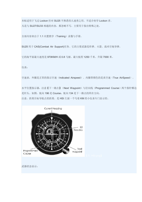
水平位置指示器,注意【下一路点】(Next Waypoint)与径向线(Programmed Course)两个指针哪边是针头。
如图,航向196是Course;航向134是下一路点的所在方向。
注意,距离目标导航点的距离,是HSI左面一个写着KM的小仪表专门显示的。
【图HSI.png】武器状态显示:瞄准具(ASP-17 Gunsight);不是“HUD”中间准星;外圈距离;小三角显示飞机当前姿态(坡度)。
瞄准具下方几个灯:左上:激光测距仪状态右上:发射许可左下:无法发射武器【图Gunsight】火控系统设置发射数量(Shift空格)和发射间隔(V)对投放炸弹非常重要。
机炮攻击也有很多设置。
机炮攻击:按7对地,按C机炮。
打。
连发、点射切换:Shift C(见火控系统相关开关的状态)有吊舱时,Shift空格切换数量。
火控显示2或4表示只使用对应数量的吊舱。
在仅使用吊舱时,可以CTRL= CTRL-调整吊舱枪口俯角。
在仅使用吊舱攻击时,开启激光测距仪(Shift o)并保持飞机坡度为0,按住扳机不放,对地开火——火控系统将自动调整吊舱俯角使炮弹落于刚刚按下扳机时瞄准的那一点。
普通炸弹攻击俯冲式:比目标高2500m以上;俯角在20到40度之间;速度700km/h;襟翼1档。
CCRP:平飞,飞近,开激光测距仪,瞄准,按住扳机不放,直飞。
DCS系统操作员站操作规程

DCS系统操作员站操作规程DCS系统操作员站操作规程1.操作员站的登录和退出1.1机组正常运行时,禁止任何人随意退出和登录操作员站。
1.2操作员站的登录除了大小修和特殊情况外,操作员站应该不存在登录问题,即在正常运行过程中不会发生登录的情况。
在大小修和特殊情况时,运行人员登录操作员站,需要在热控人员的指导下,由值长或主值同意,运行人员方可以值长或主值分配给相应的运行人员的用户名和密码登录,禁止使用和自己职责不相符的用户名和密码登录。
运行人员有权保护自己的用户名和密码。
登录窗口位于监视器右上角的菜单下的单击鼠标左键即可出现登录窗口。
1.3操作员站的退出除了大小修和特殊情况外,禁止任何人随意退出操作员站。
在大小修和特殊情况时,运行人员退出操作员站,需要在热控人员的指导下,由值长或主值同意。
退出窗口位于监视器右上角的菜单下的,单击鼠标左键即可出现退出窗口。
2.操作员站画面操作指导2.1操作员站总体画面操作介绍西门子T-XP系统操作员站画面总体分为三个区间,位于监视器上部的区间是屏幕标题,位于监视器中部的区间是基本显示区,位于监视器下部的区间是屏幕注脚。
2.1.1屏幕标题区间包括以下几部分内容::始终显示日期和时间,时间每秒刷新。
:“工厂流程”按钮。
单击本按钮,打开一个下拉菜单。
该菜单包括我厂所有流程区域画面名称。
左边的:全厂概貌图按钮。
单击本按钮,立即切换到我厂概貌图。
:报警顺序显示按钮。
单击本按钮,选择专为操作员设置的报警顺序列表。
:通用报警指示符。
F:故障(硬件),O:需要操作人员确认的故障信息,L:局部故障,A:报警,W:警告,T:允差,C:状态变化,M:维护和修理。
:“过程”按钮。
用于选择棒图/曲线的概貌画面。
左边的:全厂概貌曲线/棒图按钮。
:“IC报警显示”按钮。
专为热控工程师设置的报警显示,用于选择DCS故障报警。
:“系统”按钮。
单击本按钮,打开一个下拉菜单,本菜单包含控制下列各项内容的按钮,系统登录、报警确认、报表和长期归档。
(整理)DCSSU-25操作手册.

(整理)DCSSU-25操作手册.LOCK ON中文讲解课程本章节主要讲解苏系战机起飞操作步骤飞机起飞步骤大体分为三个部分一:启动发动机二:滑出停机坪上跑道三:起飞首先是启动发动机的步骤,我们所实用的机型是SU-25T,只所以不是SU-27,是因为SU-27T是LOCK ON中操作步骤比较复杂的机型,它的启动步骤包含其他机型的启动步骤,同时也有所复杂,所以我们用SU-25T来讲解飞机的启动步骤现在我们在SU-25T的座舱里可以看到飞机的所以仪表都处在关闭状态,因为主电源是关闭状态,我们通过Shif+“R“键打开飞机的主电源,注意仪表开始有变化,观察气压高度计,我们通过Shif+“-“和Shif+“=“将气压高度计归零,这是SU-25T在LOCK ON中的标准操作步骤,至于为什么要将它归零,我也不知道!好,一切仪表正常,准备启动发动机,我们按Ctrl+“L“键点亮翼灯,向塔台表明我们要启动发动机,确认节流阀收到低按键盘右侧(空格右边第2个键)文斗丝间和HOME键,让发动机启动,注意发动机的转速表开始变化,发动机已经启动,SU-25T是双阀战斗机,目前版本的LOCKON当中的所有可用机型都是双阀,所以我们可以单独的启动左发动机和右发动机,通过按ATT GR+HOME键来来启动左发动机,通过Shif+HOME键来启动右发动机,目前版本的LOCKON中SU-25T以及SU-25的启动步骤是相同并且是最复杂的,其他大部分机型的启动步骤中,进入座舱后,电源本身是打开的,仪表也不需要矫正,直接启动发动机即可,现在我们回到SU-25T的座舱观察仪表,发动机及启动完全属于怠速状态,接下来我们需要滑出停机坪上跑道,如果我们对于存在的机场并不熟悉的话,并不清楚上跑道的路线,这时候我们可以通过键盘左边数字键(小键盘)的4号键和6号键左右旋转头部视角,观察机场寻找上跑道路线,当然有的时候由于距离或者角度的关系,左右观察也找不到上跑道的路线,这个时候我们可以通过按F2键切换到机外视角,用小键盘的(右边数字键)“/“键和“*“键切换视角的远近,按照机场远的距离能够看清整个机场,寻找上跑道路线。
DCS操作规程

DCS 操作资料前言所谓集散控制系统(即DCS,英文名称为Distributed Control System),其含义是利用微处理机或微型计算机技术对生产过程进行集中管理和分散控制的系统,是一种新型的过程控制系统。
这个系统以多台微型计算机分散应用与过程控制全部信息通过通信网络由上位计算机监控,实现最佳化控制;通过CRT装置,通信总线键盘,打印机等装置又能高度集中地操作、显示和报警。
整个装置继承了常规模拟仪表控制系统和计算机集中控制系统的优点,并且克服了单微机控制系统危险性高度集中以及常规仪表控制功能单一,人/机联系差的缺点,可以方便地用于工业装置的生产控制和经营管理。
本《操作规程》是针对《某化工厂磷酸装置CENTUM CS3000 DCS控制系统》所做的,主要介绍了DCS系统使用方法,就正确使用该DCS系统向操作人员提供了指导性意见.本规程所涉及的操作均在操作站上实现.系统的开启与停止、操作人员口令等系统维护工作由专职人员完成,未经授权人员不得进行此操作.操作站计算机、键盘和鼠标为专用设备,严禁挪用。
特别注意:为保证系统正常运行,不允许在操作站计算机上安装运行其它与该系统无关的软件,否则将可能造成严重后果。
网络CENTUM CS 3000 可以连到V net 或以太网。
图1-6 CENTUM CS3000的网络连接图1. V网(V-net)V net 是可以连接象FCS、HIS、BCV 和CGW 站的10Mbps 实时控制总线,它可以双冗余的,有两种类型的电缆:(1)YCB111 电缆:连接除了HIS 以外的站,最大距离500m(2) YCB141 电缆:连接HIS ,最大距离185m,YCB111 电缆和YCB141 电缆可以由电缆转换器单元或总线转发器连接,当这两种电缆混合使用,最大长度按如下计算:YCB141 电缆长度+YCB111 电缆长度×0。
4≤185m2. 以太网(Ethernet)HIS与ENG、HIS 与上位机可以由以太网连在一起;上位计算机和个人计算机在以太网上可以访问CENTUM CS 3000 系统上的信息和趋势数据,以太网也也用于从HIS 发送趋势数据文件到上位机。
- 1、下载文档前请自行甄别文档内容的完整性,平台不提供额外的编辑、内容补充、找答案等附加服务。
- 2、"仅部分预览"的文档,不可在线预览部分如存在完整性等问题,可反馈申请退款(可完整预览的文档不适用该条件!)。
- 3、如文档侵犯您的权益,请联系客服反馈,我们会尽快为您处理(人工客服工作时间:9:00-18:30)。
LOCK ON中文讲解课程本章节主要讲解苏系战机起飞操作步骤飞机起飞步骤大体分为三个部分一:启动发动机二:滑出停机坪上跑道三:起飞首先是启动发动机的步骤,我们所实用的机型是SU-25T,只所以不是SU-27,是因为SU-27T是LOCK ON中操作步骤比较复杂的机型,它的启动步骤包含其他机型的启动步骤,同时也有所复杂,所以我们用SU-25T来讲解飞机的启动步骤现在我们在SU-25T的座舱里可以看到飞机的所以仪表都处在关闭状态,因为主电源是关闭状态,我们通过Shif+“R“键打开飞机的主电源,注意仪表开始有变化,观察气压高度计,我们通过Shif+“-“和Shif+“=“将气压高度计归零,这是SU-25T在LOCK ON中的标准操作步骤,至于为什么要将它归零,我也不知道!好,一切仪表正常,准备启动发动机,我们按Ctrl+“L“键点亮翼灯,向塔台表明我们要启动发动机,确认节流阀收到低按键盘右侧(空格右边第2个键)文斗丝间和HOME键,让发动机启动,注意发动机的转速表开始变化,发动机已经启动,SU-25T是双阀战斗机,目前版本的LOCKON当中的所有可用机型都是双阀,所以我们可以单独的启动左发动机和右发动机,通过按ATT GR+HOME键来来启动左发动机,通过Shif+HOME键来启动右发动机,目前版本的LOCKON中SU-25T以及SU-25的启动步骤是相同并且是最复杂的,其他大部分机型的启动步骤中,进入座舱后,电源本身是打开的,仪表也不需要矫正,直接启动发动机即可,现在我们回到SU-25T的座舱观察仪表,发动机及启动完全属于怠速状态,接下来我们需要滑出停机坪上跑道,如果我们对于存在的机场并不熟悉的话,并不清楚上跑道的路线,这时候我们可以通过键盘左边数字键(小键盘)的4号键和6号键左右旋转头部视角,观察机场寻找上跑道路线,当然有的时候由于距离或者角度的关系,左右观察也找不到上跑道的路线,这个时候我们可以通过按F2键切换到机外视角,用小键盘的(右边数字键)“/“键和“*“键切换视角的远近,按照机场远的距离能够看清整个机场,寻找上跑道路线。
机外视角并不一定打开的,我们可以通过游戏选项的设定打开或关闭机外视角,当机外视角处于关闭状态时我们按F2键是没有反映的,这个时候如果要观察机场我们可以通过按F10键进入地图视窗,通过点击上面的加号减号按钮操作鼠标来放大机场,观察自己所在停机坪位置选择上跑道路线,不过地图视窗也可以通过游戏选项选择打开或者关闭的,如果地图视窗关闭的话,我们按F10键也没有反映。
这个时候如果要选择外部的视角观察机场的话,我们可以通过按F11键,如果我们所看到的机场不是自己所在的机场,我们可以通过不停的按F11键,可以在目前LOCK ON中使用的20个机场中来回的切换,我们可以一直切换到发现自己所在的机场,然后再通过小键盘的“/“键和“*“拉近拉远视角,找到自己上跑道的路线,我们知道这很麻烦,当然我也只是想告诉你们能够从外面看清楚自己机场的几种方法。
其实最好的方法是能有另一架飞机在跟你相同的机场,在你的面前滑出起飞,这样你只要跟着它就可以了!LOCK ON目前拥有20个机场,每一个机场的停机坪位置都是不同的,并且即使在同一个机场随着飞机起飞架次与时间的不同,玩家所操作的飞机停机坪位置也会不同,所以最根本的方法还是要熟悉LOCKON中的机场。
玩家可以在通过在3GO网站下载由101编写的LOCKON机场地图手册对于各个机场进行查阅,熟悉。
玩家尤其在进入游戏之前通过编辑器了解自己飞机所在哪一个机场,在再进入游戏后通过对应地图手册来寻找上跑道路线。
LOCK ON中的机场跑道都有其余固定的起飞和降落方向,除了在特殊的天气情况影响下之外,跑道的起飞和降落方向都是不变的。
我们可以通过查阅LOCK ON地图手册来了解跑道的固定起飞和降落方向,也可以通过观察电脑控制飞机的起飞和降落方向来了解跑道的固定起飞和降落方向。
当然由于目前LOCK ON中的机场并不是非常的繁忙,所以我们可以以自己的方便为原则自行选择起飞的方向,前提是不能影响其他飞机的起飞和降落。
确定上跑道的路线后就可以滑出停机坪上跑道,按Ctrl+“C“键关闭座舱盖,按Shift+“F“键将机翼完全展开(放下襟翼),按小键盘的“/“键调出无线电菜单,按F6键选择塔台频道,按F1键选择请求滑出,在得到塔台的应许后,按ALT GR+“L“键打开起落架大灯,表明你正在滑出,将操纵杆上的节流阀稍稍前推,或者通过键盘上的小键盘“+“和“-“键小幅度的控制发动机使飞机开始缓慢的向前滑动。
飞机在滑出停机坪的速度中最好不要超过10公里每小时,当速度过快的时候,我们可以通过键盘上的W键来进行刹车,滑出停机坪后我们可以通过操纵杆上的Z轴或者脚踏来使飞机转向,也可以通过键盘上的Z键和X键来启到所有蹬舵的作用,然后使飞机按照事先所观察的上跑道路线行迹。
在从滑行道上跑道的过程中,我们要注意飞机的速度也不能过快,在LOCKON电脑控制飞机的滑行速度一般是13公里每小时左右,我们可以以此为参照,当然这实在是太慢了。
在空旷的滑行道上我们可以适当的提高速度,前提是不能妨碍其他飞机的滑行。
同时我们还要注意的是当飞机要转弯的时候我们要将飞机速度降到低于20公里每小时,否则的话飞机可能冲出滑行道,造成机翼搽地爆胎甚至更严重的后果,当我们滑行至上跑道位置后要刹车,通过键盘中的小键盘数字键上下左右移动视角,确定没有飞机在同一跑道上起降,这时上跑道。
对正跑道后按刹车(W键机轮刹车)将飞机停住,按“/“键选择无线电菜单,按F6键选择塔台频道,按F2键选择请求起飞。
在得到塔台的准许起飞指令后,确认机翼完全展开(Shift+“F“键),按住刹车键(W)将节流阀平缓的向前推动(推动节流阀小键盘“+“和“-“键),当发动机转速达到%90以后松开刹车,将节流阀推到头,飞机开始向前滑行。
没有飞行操纵杆的玩家可以通过小键盘上的“+“和“-“号键小幅度控制发动机,也可以通过“PAGEUP“和“PAGEDOWN“键大幅度控制发动机,(也就是控制节流阀)。
在滑行过程中随时矫正滑行方向,当速度达到280公里每小时时向后拉杆飞机起飞。
(拉杆键盘方向键)!确定飞机离地后按G键收起落架。
保持核实两角,所谓的核实合适两角,就是确定你的速度是在增加,同时你的垂直速度是否保持在正直。
当飞机的高度大于100米的时候按Shift+“F“键完全收起机翼。
按Shift+L“键两次关闭翼灯。
目前的版本LOCK ON中SU-25T的操作是最为复杂的。
比如它的翼灯就有三种模式,打开;闪烁;关闭。
我们通过按Shift+“L“键在三种模式中来回的切换。
其他的机型翼灯一般分为两种模式。
打开,或者关闭。
我们也可以通过Shift+“L“键在两种模式中切换。
在翼灯进行切换的时候,建议在舱内保持观察翼灯视角,确定你所在你所要的状态下。
我们刚刚完成了SU-25T的起飞步骤,需要说明的是,在LOCK ON中,苏系战机中所实用的速度单位是公里每小时,高度单位是米。
而美系战机中所实用的速度单位以及高度单位为英尺。
因此在操纵美系战机的时候起飞步骤中看到的数据与苏系战机是不同的。
美系的起飞速度一般是150节左右。
需要玩家注意!!在模拟飞行游戏中LOCK ON的起飞步骤算是比较简单的,玩家在实际飞行中其中的大量步骤可以从简一些,只需要注意熟悉启动发动机,关座舱盖,放机翼,上跑道起飞,收起落架,收机翼五步即可!SU系战机起飞过程就先讲到这里,感谢阅读。
