张本余一世之FX0N-3A学习笔记
读书笔记优秀模板
读书笔记优秀模板读书笔记优秀模板篇1抱着处理商务的态度,我不情愿地拿起这本我早已忘记的《简爱》,不得不承认我的阅读态度随着故事的发展而起伏。
我被这个故事深深吸引了。
当小简爱被责骂时,我不禁同情这个被命运捉弄的孩子,或者在她的眼里,这种所谓的同情就是对她的蔑视。
她不需要它。
童年的悲惨经历使她讨厌它,也使他讨厌它。
也许海伦和坦普尔小姐的出现教会了她改变,但在我们的闲暇时间,我们不得不感叹当时社会的无情和冷漠。
随着简爱的获救,我不禁为她欢呼。
当他勇敢地拒绝圣约翰的求婚并坚持他的真爱时,我被她的选择感动了。
当她照顾已经残疾的罗切斯特时,她带给人们的不仅仅是感动,更是震撼他们的心灵。
读书笔记优秀模板篇2看完了《诗经》再看《老子》,一部部不朽经书让我获益,并让我不禁迷惑:几千年前的先秦诸子百家是如何悟到这些道理的呢?但是这些字字珠矶的作品对我来说还是有些深奥了,咬牙读了几本后,我把信心全部放在《论语》上。
两千五百多年前,孔子教学和生活中的点点滴滴被学生片片断断记录下来,这些以课堂笔记为主的记录由他的学生汇集编写,后来就成了《论语》。
中国历史从汉武帝开始,尊儒学为统治思想,《论语》治天下。
可见《论语》在古代社会生活中发挥的巨大作用以及古人对它的推崇。
大家不要认为孔夫子的《论语》像一座大雪山,只有那些专业人士才能攀上去,其实不然。
在我看来,《论语》更像一碗热腾腾的鸡汤,喝下去后让心灵得到一次洗涤。
孔子的《论语》很少长篇大论,每一则都很简练。
因为无言也是一种教育,子曰:“天何言哉?四时行焉,百物生焉。
天何言哉?”这句短语就是最好的叙述。
中华民族五千年的历史是一路跌跌撞撞,一身伤痕闯过来的。
全世界都惊叹于我们,因为我们的一种信念,孔夫子就是一个很有信念的人。
子贡问政。
子曰:“足食,足兵,明信子矣。
”子贡曰:必不得已而去,于斯三者何先。
子曰:“去兵”。
子贡曰:“比不得已而去,于斯二者先何先?”子曰:“去食”。
自古皆有死,民无信不立。
三次数学危机 读书笔记
三次数学危机读书笔记《三次数学危机》是匹克特和克里舍夫斯基的合著作品,讲述了数学在过去三个世纪中所面临的三个重大危机,分别是不可能几何、代数基础危机和连续统计危机。
下面是我的读书笔记。
第一次数学危机:不可能几何。
不可能几何问题主要涉及到尺规作图的限制。
17世纪,费马提出了尺规作图三个基本问题的解决方案,但在19世纪,谢尔皮引用琴塔拉托证明了某些问题是无法通过尺规作图解决的。
这个危机迫使数学家们重新思考几何学的基础和方法,最终导致了非欧几何的产生。
第二次数学危机:代数基础危机。
20世纪初,希尔伯特提出了23个数学公理,希望通过这些公理来建立一个统一的数学体系。
然而,哥德尔在1931年的不完备性定理证明了任何一个包含基本算术的公理体系都存在无法证明或证伪的命题。
这个发现颠覆了希尔伯特的计划,数学家们纷纷转向了构造性数学和模型论的研究。
第三次数学危机:连续统计危机。
20世纪末,统计学和概率论在实际应用中的成功使得人们开始对数学中真实连续和理想离散之间的关系进行思考。
福克斯和莱利在1973年的论文中提出了连续和离散之间的桥梁——分形集合。
这个概念让人们重新审视了现实世界的物理现象和数学模型之间的联系,并使得数学家们对于数学的本质和局限性有了更加深入的理解。
通过阅读《三次数学危机》,我对数学的发展历程有了更深入的了解。
不可能几何、代数基础和连续统计问题的提出和解决过程,揭示了数学作为一门科学的内在矛盾和发展方向的变化。
这些危机和变革不仅仅是数学领域的问题,而是关于人类认识世界和建立知识体系的思考。
总而言之,《三次数学危机》是一本引人深思的书籍,它通过讲述数学中的危机和变革,展示了人类思维的发展和数学科学的进步。
它不仅适合数学爱好者阅读,也适合对科学哲学和知识体系有兴趣的读者。
留数定理公式总结

留数定理公式总结留数定理是复变函数论中的一个重要定理,在数学分析和工程技术等领域都有着广泛的应用。
咱们先来瞅瞅留数定理的公式到底是啥样的。
留数定理表述为:设函数$f(z)$在区域$D$内除有限个孤立奇点$z_1,z_2,\cdots,z_n$外处处解析,$C$是$D$内包围诸奇点的一条正向简单闭曲线,那$f(z)$沿$C$的积分就等于$2\pi i$乘以$f(z)$在$C$内各奇点的留数之和,即:$\oint_C f(z)dz = 2\pi i \sum_{k = 1}^{n}Res[f,z_k]$这里的$Res[f,z_k]$表示$f(z)$在奇点$z_k$处的留数。
那留数又咋算呢?对于孤立奇点$z_0$,如果它是可去奇点,那留数为$0$;如果是$m$阶极点,就有公式$Res[f,z_0] = \frac{1}{(m -1)!}\lim_{z \to z_0}\frac{d^{m - 1}}{dz^{m - 1}}[(z - z_0)^mf(z)]$。
咱们通过一个具体例子来感受一下留数定理的魅力。
比如说,计算积分$\int_{|z| = 2} \frac{e^z}{z(z - 1)}dz$。
首先得找出被积函数的奇点,很明显,$z = 0$和$z = 1$是奇点。
对于$z = 0$,它是一阶极点,$Res[f,0] = \lim_{z \to 0} z\frac{e^z}{z(z - 1)} = -1$;对于$z = 1$,也是一阶极点,$Res[f,1] = \lim_{z \to 1} (z - 1)\frac{e^z}{z(z - 1)} = e$。
然后根据留数定理,原积分就等于$2\pi i (-1 + e)$。
留数定理在解决一些复杂的积分问题时特别有用。
比如说,计算一些实函数在无穷区间上的积分,通过巧妙地构造复变函数和积分路径,然后利用留数定理就能轻松搞定。
我记得有一次给学生们讲留数定理的应用,有个学生就特别迷糊,怎么都搞不明白。
第3章习题答案
“微处理器系统原理与嵌入式系统设计”第三章习题解答3.1什么是冯·诺伊曼计算机结构?其运行的基本原理如何?冯.诺依曼计算机由运算器、控制器、存储器、输入设备和输出设备构成,采用二进制表示信息,以存储器为中心,按存储程序原理工作。
存储程序原理指编好的程序首先放入存储器,开始工作后,由控制器自动、高速依次从存储器中取出指令并执行。
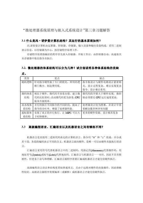
3.2. 微处理器的体系结构可以分为几种?试分别说明各种体系结构的优缺点。
3.3 高级编程语言、汇编语言以及机器语言之间有哪些不同?机器语言是直接用二进制代码表达的计算机语言。
指令用“0”和“1”组成,并分成若干段,各段的编码表示不同的含义。
机器语言面向硬件,是唯一可以由硬件直接执行的语言。
汇编语言采用符号代替机器语言中的二进制码:用助记符(Mnemonic)代替操作码,用地址符号(Symbol)或标号(Label)代替地址码。
汇编语言与机器语言一一对应,因此不具有移植性,但更易于读写和理解。
汇编语言源程序需要汇编成机器语言才能交给硬件执行。
高级编程语言语法和结构更类似普通英文,且由于远离对硬件的直接操作,因此移植性较好。
高级语言源程序需要编译(或解释)成机器语言才能交给硬件执行。
3.5 什么是计算功能指令、数据传输指令以及控制流程指令?计算功能指令:对数据进行处理完成算术运算或逻辑运算等的指令。
数据传输指令:负责把数据、地址或立即数传送到寄存器、I/O端口或存储单元中,或者反方向传送的指令。
控制流程指令:用来控制程序执行流程的指令,有测试、转移、跳转等子类。
3.6 解释跳转、分支、调用以及中断所需进行的操作。
跳转:根据“跳转”指令指计算目的地址,修改程序指针。
分支:根据“分支”指令判断执行条件,计算跳转地址,修改程序指针。
调用:保存断点,根据“调用”指令计算子程序入口地址,修改程序指针,执行完毕后恢复断点。
中断:保护断点及现场,查找中断向量表以确定中断程序入口地址,修改程序指针,执行完毕后恢复现场及断点。
学习三信的心得体会范文(精选16篇)

学习三信的心得体会范文(精选16篇)学习三信的范文篇1为了促进三信教育活动的深入开展,我局积极创新学习形式、丰富学习载体,以六学形式切实抓好理论学习工作,确保三信教育活动扎实有序开展。
刚才组织学习了王中书记动员讲话,明确了教育活动的科学内涵、精神实质、根本要求和重大意义,我们要准确理解和把握为什么必须坚定信仰、为什么必须坚定信念、为什么必须坚定信心这个中心命题,自觉地把思想认识统一到镇委的部署要求上来,不断增强搞好三信教育活动的责任感和使命感。
一是要充分认识到三信教育是提高党性觉悟、强化党员意识的迫切需要。
党性觉悟、党员意识是共产党员的立身之本,是党保持和发展先进性的重要前提。
强化共产党员的意志品质、坚定理想信念,是加强党的建设、保持先进性的永恒主题。
我局现有在职党员66名,占在职干部总数的80%,这样大的一个党员队伍,是我镇环保战线的宝贵财富,教育好、利用好,将会催生一股巨大的战斗力量。
如何充分利用好我们党员队伍优势、保持好党员干部的优良素质、发挥好党员干部的先锋模范作用,是我局三信教育活动首先要解决好的问题。
这次教育活动,重点要通过学习党的基本理论知识、接受红色革命传统教育等内容,用党的理论武装头脑,从根本上提高思想政治觉悟和党员意识,牢固树立大局意识和奉献意识,努力打造一个极富向心力、凝聚力的战斗集体,建设一支意志坚强、意识一流、素质一流、作风一流的的党员队伍,激励全局党员坚定理想信念,遵守组织纪律,争当先锋模范,推进各项工作顺利开展。
二是要充分认识到三信教育是提高党员执行能力、服务能力的迫切需要。
共产党员应当是党的路线、方针的坚定拥护者、执行者,应当是各级党委政府工作目标的坚定践行者、推进者,应当是群众利益的坚定维护者、服务者。
只有具备一定的执行能力、服务能力,才算得上是一名合格的党员。
在我们的工作实践中,存在着对某些法律法规的理解不透、执法不力的问题,存在着面对群众投诉的某些环境难题无法解决、无力解决的问题,归根结底,是我们的执行能力不强、服务本领不高的问题。
计算机系统结构--《张晨曦、王志英》课后习题参考答案

第1章计算机系统结构的基本概念1.1 解释下列术语层次机构: 按照计算机语言从低级到高级的次序, 把计算机系统按功能划分成多级层次结构, 每一层以一种不同的语言为特征。
这些层次依次为: 微程序机器级, 传统机器语言机器级, 汇编语言机器级, 高级语言机器级, 应用语言机器级等。
虚拟机: 用软件实现的机器。
翻译: 先用转换程序把高一级机器上的程序转换为低一级机器上等效的程序, 然后再在这低一级机器上运行, 实现程序的功能。
解释: 对于高一级机器上的程序中的每一条语句或指令, 都是转去执行低一级机器上的一段等效程序。
执行完后, 再去高一级机器取下一条语句或指令, 再进行解释执行, 如此反复, 直到解释执行完整个程序。
计算机系统结构: 传统机器程序员所看到的计算机属性, 即概念性结构与功能特性。
在计算机技术中, 把这种本来存在的事物或属性, 但从某种角度看又好像不存在的概念称为透明性。
计算机组成: 计算机系统结构的逻辑实现, 包含物理机器级中的数据流和控制流的组成以及逻辑设计等。
计算机实现: 计算机组成的物理实现, 包括处理机、主存等部件的物理结构, 器件的集成度和速度, 模块、插件、底板的划分与连接, 信号传输, 电源、冷却及整机装配技术等。
系统加速比: 对系统中某部分进行改进时, 改进后系统性能提高的倍数。
Amdahl定律: 当对一个系统中的某个部件进行改进后, 所能获得的整个系统性能的提高, 受限于该部件的执行时间占总执行时间的百分比。
程序的局部性原理: 程序执行时所访问的存储器地址不是随机分布的, 而是相对地簇聚。
包括时间局部性和空间局部性。
CPI: 每条指令执行的平均时钟周期数。
测试程序套件: 由各种不同的真实应用程序构成的一组测试程序, 用来测试计算机在各个方面的处理性能。
存储程序计算机: 冯·诺依曼结构计算机。
其基本点是指令驱动。
程序预先存放在计算机存储器中, 机器一旦启动, 就能按照程序指定的逻辑顺序执行这些程序, 自动完成由程序所描述的处理工作。
数学奥林匹克小丛书初中卷第三版因式分解技巧

《数学奥林匹克小丛书初中卷第三版因式分解技巧》一、引言在学习数学的过程中,因式分解是一个非常重要且基础的概念。
它不仅在解题的过程中起着关键性作用,而且对于扎实的数学基础和逻辑思维能力的培养也具有重要意义。
而《数学奥林匹克小丛书初中卷第三版》中关于因式分解的技巧更是为我们提供了宝贵的学习资源和指导,帮助我们更好地掌握这一重要知识点。
二、从简到繁,由浅入深的因式分解技巧1. 提取公因式在因式分解的过程中,首先要掌握的就是提取公因式的技巧。
这是因式分解的基础,也是解题过程中最常见的一种方法。
在《数学奥林匹克小丛书初中卷第三版》中,通过大量的例题和解析,深入浅出地阐述了提取公因式的原理和方法,从而让我们更好地掌握这一技巧。
2. 分解因式除了提取公因式外,分解因式也是因式分解过程中的重要步骤。
《数学奥林匹克小丛书初中卷第三版》中提供了丰富多样的分解因式的题目,并给出了详细的解题思路和方法,帮助我们更好地理解和掌握这一技巧。
3. 特殊方法与技巧除了基础的提取公因式和分解因式外,《数学奥林匹克小丛书初中卷第三版》还介绍了一些特殊的因式分解方法和技巧,如差的平方公式、完全平方公式等。
这些特殊的方法和技巧,往往能在解题过程中起到意想不到的作用,因此对于我们来说也至关重要。
4. 延伸拓展《数学奥林匹克小丛书初中卷第三版》中不仅仅停留在基础的因式分解技巧上,还对其进行了更深远的延伸拓展。
更复杂的多项式的分解、高次方程的因式分解等。
这些内容的介绍和讲解,对于我们更深入地理解因式分解技巧以及应用它们解决实际问题都具有重要意义。
三、个人观点和理解在学习《数学奥林匹克小丛书初中卷第三版》中关于因式分解的技巧时,我深刻地体会到了因式分解在数学学习中的重要性。
它不仅是解题的利器,更是培养我们逻辑思维和分析问题能力的重要途径。
而《数学奥林匹克小丛书初中卷第三版》所提供的丰富多样的例题和详细解析,让我受益匪浅。
在未来的学习中,我也会进一步加强对因式分解技巧的掌握,努力提高解题能力和数学素养。
感想文の书き方

3、~ば~ほど 梦想越大越好。 夢は(大きければ)大きいほどいい。 那本书越赌越有趣。 その本は読めば読むほどおもしろい。
4、~たら(在某个事实已经成立的条件下,把 那个事实作为前提条件进行叙述。) 一下子吃那么多的话对胃不好。 一度にそんなにたくさん食べたら、胃によくな い。 到了春天去爬山吧。 春になったら、登山にでも行こう。 每天都喝酒的话对身体不好。 毎日お酒を飲んだら体によくない。
二
感想文を書くときの心構え
1、心に浮かぶままを飾らずに書き記し、きちんとした 文章の組み立てにあまりこだわりません。 2、一番書きたいところを詳しく書くようにします。 3、自分の気持ちを隠さずに、思ったままをさらけ出す ように書いていきます。 4、自分らしい考え方やものの見方がよく現れるように 書きます。 5、整然と論理を積み上げたり、鋭い議論を展開したり するよりも、文章全体にふんわりとした気分が現れるよ うに書きます。
LOGO
ありがとうござい ました!
LOGO
第2課
感想文の書き方刘萍外国语学院一 感想文の特徴
自分のまわりのいろいろな事柄や出来事に対し て、自分の心の中で感じたこと、思ったことを まとめて書いたものが感想文です。随筆ともい います。公表するかしないかは別として、こう した感想文を絶えず書いていると、文章表現力 も伸びます。
感想文は感じたことと思ったことをそのまま文 章にまとめるのですから、書くことも比較的楽 です。書こうとする事柄もたくさんあります。
5、~と(表示条件、紧接着发生、时间、逆接 等多种意思。) 一到外面就开始下雨了。 外に出ると雨が降り出した。 回家一看谁也不在。 家に帰ってみるとだれもいなかった。 如果真和他聊一聊,就会觉得他不是那么坏的 人。 実際に話してみると、彼はそんなに悪い人では ない。
角域内分担小函数的亚纯函数的唯一性定理
些 重要 的唯 一性 定理 被 延伸到 了角域 ( 见 文献 『 1 - 3 , 1 1 ] 等) . 在这 些 已有 的角域 内亚纯 函数 的唯 一性 结果 中,角域 内 N e v a n l i n n a理 论起 了关键 的作
用 .但是 角域 内 N e v a n l i n n a理论 对余 项估 计 的不 完美性 使 得这 项研 究变 得 很 困难 .在 文献 r 1 0 1 中, Z h e n g J H将 T s u j i 特 征 函数应 用 到此课 题 的研 究 中,将 复 平面上 亚纯 函数 唯一性 的一些 重要 结果 延伸 到 了角域 ( 包括 N e v a n l i n n a五值 定理 ) . 因此 T s u j i 特 征 函数可 能成 为此
和g I M 分担 .
设 。 厂为角 域 【 2 ( , ) = z: <a r g Z< )内的亚 纯 函数 ,其 中 0< 一
2 7 r . 令
三 ( a , , r ) ={ =t e i : O Z <0 < , l <t r ( s i n ( w ( O — ) ) ) / } ,
Hale Waihona Puke 卢 ( r j , ) r j , ) 一
。
n ( r 、k l o g + J , ( r e i ( a +  ̄ - 1 0 ) s i n w - 1 0 ) I f
m ~ ’
收稿 日期: 2 0 1 2 — 0 3 — 1 4 ; 修订 日期: 2 0 1 3 — 0 4 — 2 6
MR( 2 0 0 0 )主题分类: 3 0 D 3 0 ; 3 0 D 3 5 中图分类号: O1 7 4 . 5 5 文献标识码: A 文章编号:1 0 0 3 — 3 9 9 8 ( 2 0 1 3 ) 0 6 — 1 0 4 5 — 0 7
对数与对数运算PPT

思考:
在指数式 ax N和对数式 x= loga N中, a,x ,N 各自的地位有什么不同?
指数式 ax N 对数式 x= loga N
a Nx
指数的底 幂 幂指数 数
对数的底 真 对数 数数
对数式与指数式的互换
42 16 化为对数式 log4 16 2
102 100 化为指数式 log10 100 2
1
4 2 2 化为对数式
102 0.01 化为指数式
1 log 4 2 2
log10 0.01 2
对数的运算
对数运算的三条基本性质
(1)loga M loga N loga (M N)
(2)loga
M
loga
N
loga
M N
(3)loga M n n loga M
对数运算的三个常用结论
ax N x= loga N
介绍两种特殊的对数:
1.常用对数:以10作底 log10 N写成 lg N
例如:log10 3简记作lg 3,log10 2.3简记作lg 2.3 ;
2.自然对数:以无理数e = 2.71828…作
底 log e N 写成 ln N
例如:loge 3 简记作 ln 3,loge 7.1简记作ln 7.1 ;
(1)loga a 1; (2) loga 1 0;
(3) aloga N N.
课堂练习
试用 loga x,loga y ,loga z表示下式:
(1) loga
x2 y
(2)loga yz2
小结:
1°对数的定义
2°互换(对数与指数会互化)
3 °对数的运算性质
课后延续
1、认真复习;
《赢》读后感
《赢》读后感《赢》读后感1执行实际是一门学问,是一门教你学会如何完成任务的学问,大多数情况下,公司和它的竞争对手之间差别就在于双方执行的能力。
正如书中开篇第一章所指出:中国企业不缺技术、人才与战略,严重缺失的是执行力。
执行已经成为今天的企业界所共同关心的一个问题,执行正成为企业成功的一个关键因素!我认为作者的本意是在告知我们这样的道理,不能片面地看待某一观点,追求速度的同时还要想到完美。
问题的关键是执行人对执行的理解,这取决一个人的基本素质高底,对企业文化,对工作环境,社会环境的认知程度。
作者还阐述这样一个观点。
执行的关键是如何做到正确的执行,书中所谓的矛盾其用意也在于此。
通过《赢在执行》一书中这么多的案例还让我感悟了这样一个观点,企业自身要有良好的执行氛围,让执行植根与企业文化中。
让全体员工有良好的执行环境。
那么怎样才能使企业快速提高执行力呢?除了书中所讲的执行力不佳的八个原因以及提升执行力的方法外,根据我个人在实际工作中的体会浅说以下三点:第一、管理要标准化、程序化、数据化。
要想时针走的准确必须控制好秒针的`运动。
高效的的执行来源与精确的管理,精确的管理必是精细的管理,凡是精细的管理,一定是标准化的管理、一定要经过严格的程序化的管理,最终是科学的数据化管理。
第二、集中与民主相统一、细节与简约相统一。
要想做到提升执行力,就首先要理解他。
什么是执行力?执行力就是部门和个人理解、贯彻、落实、执行企业决策的能力。
不难看出,执行力是要部门和个人相配和完成的,不是只靠个人执行就叫有效执行了,部门也要有行之有效的操作流程。
二者结合在一起才能说这个企业的执行力强。
关键点又回到了团队配合,就像新的木桶理论,现在看木板不能只看短长了,如果所有木板都长了,但板与板之间拼扣得不紧,水也装不满。
其实高效的执行首先是正确的执行,要做到正确的执行,在组织上要集中与民主相统一。
在工作中要细节与简约相统一。
就如琴弦过紧回崩、松而无音。
FX0N-3A
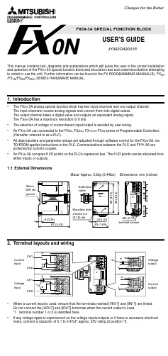
FX 0N -3A SPECIAL FUNCTION BLOCKUSER’S GUIDEJY992D49001EThis manual contains text, diagrams and explanations which will guide the user in the correct installation and operation of the FX 0N -3A special function block and should be read and understood before attempting to install or use the unit. Further information can be found in the FX PROGRAMMING MANUAL(ΙΙ), FX 0N /FX 1N /FX 2N /FX 2NC SERIES HARDWARE MANUAL.1.Introduction•The FX 0N -3A analog special function block has two input channels and one output channel. The input channels receive analog signals and convert them into digital values. The output channel takes a digital value and outputs an equivalent analog signal. The FX 0N -3A has a maximum resolution of 8 bits.•The selection of voltage or current based input/output is decided by user wiring.•An FX 0N -3A can connected to the FX 2N , FX 2NC , FX 1N or FX 0N series of Programmable Controllers (Hereafter referred to as a PLC).•All data transfers and parameter setups are adjusted through software control for the FX 0N -3A, via TO/FROM applied instructions in the PLC. Communications between the PLC and FX 0N -3A are protected by a photo-coupler.•AnFX 0N -3A occupies 8 I/O points on the PLC’s expansion bus. The 8 I/O points can be allocated from either inputs or outputs.1.1External Dimensions2.Terminal layouts and wiring•When a current input is used, ensure that the terminals marked [VIN*1] and [IIN*1] are linked. Do not connect the [VOUT] and [IOUT] terminals when the current output is used.*1terminal number 1 or 2 is identified here.•If any voltage ripple is experienced on the voltage inputs/outputs or if there is excessive electrical noise, connect a capacitor of 0.1 to 0.47µF , approx . 25V rating at position *2.Mass: Approx. 0.2kg (0.44lbs) Dimensions: mm (inches)3.Connection with PLC1)Up to 4 FX0N-3A units can connect to the FX0N series PLC, up to 5 for FX1N, up to 8 for FX2N or, up to4 for an FX2NC series PLC, all with powered extension units.However the following limitation exists when the undermentioned special function blocks are con-nected.FX2N:Main unit and powered extension units of 32 I/O points or less. Consumption current available for undermentioned special function blocks ≤ 190mAFX2N:Main unit and powered extension units of 48 I/O points or more. Consumption current available for undermentioned special function blocks ≤ 300mAFX2NC:Up to 4 undermentioned special function blocks can be connected regardless of the system I/O. FX0N/1N:Main unit and powered extension units. Up to 2 undermentioned special function blocks can be connected regardless of the system I/O.The consumption current of the above units is to be subtracted from the service power supply of the host PLC.2)FX0N-3A consumes 5V DC by 30mA. The total 5V consumption of all special function blocksconnected to either the FX2N or FX2NC main unit or an FX2N extension unit must not exceed the 5V voltage source capacity of the system.3)The FX0N -3A and main unit are connected by a cable on the right of the main unit.4.Installation notes and Usage4.1General and Environmental Specifications4.2Performance SpecificationsFX2N-2AD FX2N-2DA FX0N-3A Consumption current of 24V DC for one unit.50mA85mA 90mAItem SpecificationGeneral specifications(ex. withstand voltage)Same as those for the main unitWithstand Voltage500V AC for 1 minute (between ground and all other terminals) Analog circuit power requirement24V DC +/- 10%, 90mA (internal power supply from main unit) Digital circuit power requirement5V DC, 30mA (internal power supply from main unit)IsolationPhoto-coupler isolation between analog and digital circuit.No isolation between analog channels.Number of occupied I/O points8 I/O points from expansion bus. (either input or output)Voltage input Current inputAnalog input rangeAt shipment, 0 to 250 range selected for 0 to 10V DC input.When using an FX0N-3A for current input or differing voltage inputs except 0 to10V DC, it is necessary to readjust the offset and gain.The module does not allow different input characteristics for two channels.0 to 10V, 0 to 5V DC, resistance200kΩ. Warning: this unit may bedamaged by input voltages in excessof -0.5V, +15V.4 to 20mA, resistance 250Ω. Warning:this unit may be damaged by inputcurrents in excess of -2mA, +60mA. Digital resolution8 bitsSmallest input sig-nal resolution40mV: 0 to 10V/0 to 250(At shipment)Change depending on the inputcharacteristic.64µA: 4 to 20mA /0 to 250Change depending on the inputcharacteristic.Overall accuracy± 0.1V± 0.16mAProcessing time TO instruction processing time x 2 + FROM instruction processing timeInput characteristicsThe module does not allow different input characteristics for two channels.[At shipment]5.Allocation of Buffer Memories (BFM)When FNC176(RD3A) and FNC177(WR3A) are used with FX 1N ,FX 2N (V3.00 or more) or FX 2NC (V3.00 or more), the allocation of the buffer memory (BFM) need not be considered. •BFM 17:b0 = 0 analog input channel 1 is selected b0 = 1 analog input channel 2 is selectedb1 = 0 Ö1, the A/D conversion process is started b2 = 1 Ö 0, the D/A conversion process is started•Note: These buffer memory devices are stored/located within the FX 0N -3A6.Diagnostics6.1Preliminary Checksa)Check whether the input/output wiring and/or expansion cables are properly connected.b)Check that the system configuration rules for the host PLC have not been broken.c)Ensure that the correct operating range has been selected for the application.d)As the status of the PLC changes (RUN Ö STOP , STOP Ö RUN, etc.), the analog output status willoperate in the following manner.Status change of the host PLC:-RUN Ö STOP: The last operational value used by the analog output channel during RUN operation is retained during STOP mode.-STOP Ö RUN: Once the host PLC is switched back into RUN mode the analog output reacts as normal to the program controlled, digital values.PLC power shutdown: The analog output signal ceases operation.e)Remember that only 8 bit digital values (0 to 255) are valid for use with the analog output of theFX 0N -3AVoltage output Current outputAnalog output rangeAt shipment, 0 to 250 range selected for 0 to 10V DC output.When using an FX 0N -3A for current output or differing voltage output except 0 to 10V DC, it is necessary to readjust the offset and gain.DC 0 to 10V , 0 to 5V external load: 1k Ω to 1M Ω4 to 20mA, external load: 500Ω or less Digital resolution 8 bitsSmallest output signal resolution 40mV: 0 to 10V/0 to 250(At shipment)Change depending on the input characteristic.64µA: 4 to 20mA /0 to 250Change depending on the input characteristic.Overall accuracy ± 0.1V± 0.16mAProcessing timeTO instruction processing time x 3OutputcharacteristicsIf digital source data of greater than 8 bits is used, only the lower 8 bits will be valid. Additional (upper) bits will be ignoredBFM No.b15-b8b7b6b5b4b3b2b1b00ReservedCurrent value input data (stored in 8 bits) of the A/D channel selected by b0 of BFM#1716Current value output data on D/A channel (stored in 8 bits)17ReservedD/A startA/D startA/D channel1-5,18-31Reserved[At shipment]7.Change and adjustment method of input/output characteristic7.1Change in input/output characteristicAt shipment, 0 to 250 range selected for 0 to 10V DC input/output.When using an FX 0N -3A for current input/output or differing voltage input/output except 0 to 10V DC, it is necessary to readjust the offset and gain.The module does not allow different input characteristics for two channels.Set analog values from 0 to 250 digital equivalent within the range specified in the table below when changing the input/output characteristic. Range of allowance of input/output characteristicResolution changes depending on the set value when the input/output characteristic is changed. Example: Resolution becomes (5 to 0V)/250=20mV at voltage input 0 to 5V/0 to 250. Overall accuracy does not change. (Voltage input : ±0.1V , Current input: ±0.16mA)7.2Method of Calibration(A/D)Both analog input channels share the same ‘setup’ and configuration. Hence only one channel needs to be selected to perform the calibration for both analog input channels.Use the following program and the appropriate wiring configuration to calibrate input channel 1 (and indirectly channel 2) of the FX 0N -3A.7.2.1Input Calibration Program7.2.2Calibrating the Offset1)Run the previously detailed program. Ensure X02 is ON.2)Generate an offset voltage/current (in accordance with the analog operation range to be selected, seetable below) using the selected generator or analog output.3)Adjust the A/D OFFSET potentiometer (‘pot’) until a digital value of 1 is read in D00.Note : T urn the ‘pot’ clockwise and the digital value will increase. The ‘pot’ requires 18 revolutions tomove between the minimum and maximum settings.7.2.3Calibrating the Gain1)Run the previously detailed program. Ensure X02 is ON.2)Generate a gain voltage/current (in accordance with the analog operation range to be selected, seetable below) using the selected generator or analog output.3)Adjust the A/D GAIN potentiometer (‘pot’) until a digital value of 250 is read in D00.Note 1:T urn the ‘pot’ clockwise and the digital value will increase. The ‘pot’ requires 18 revolutions tomove between the minimum and maximum settings.Note 2:When necessary to maximize the 8 bit resolution, the digital value used in the gain adjustment(detailed above) should be replaced with 255. This section has been written to demonstrate 250full scale calibration.Voltage inputCurrent input Voltage output Current output Analog value when digital value is 00 to 1V 0 to 4mA 0V 4mA Analog value when digital value is 2505 to 10V20mA5 to 10V20mAAnalog input range 0-10V DC 0-5V DC 4-20mA DC Offset calibration value 0.040V0.020V4.064mAAnalog input range 0-10V DC 0-5V DC 4-20mA DC Gain calibration value10.000V5.000V20.000mATO K0K17H00K1K0K17H02K1K0K0D0K1TOX02FROM7.3Method of Calibration(D/A)Use the following program and the appropriate wiring configuration to calibrate the output channel of the FX0N-3A7.3.1Output Calibration Program7.3.2Calibrating the Offset1)Run the previously detailed program. Ensure X00 is ON and X01 is OFF.2)Adjust the D/A OFFSET potentiometer (‘pot) until the selected meter displays the appropriate offsetvoltage/current (in accordance with the analog operation range selected, see table below).Note:T urn the ‘pot’ clockwise and the analog output signal will increase. The ‘pot’ requires 18 revolutions to move between the minimum and maximum settings.7.3.3Calibrating the Gain1)Run the previously detailed program. Ensure X00 is OFF and X01 is ON.2)Adjust the D/A GAIN potentiometer (‘pot’) until selected meter displays the appropriate gain voltage/current (in accordance with the analog operation range selected, see table below).Note 1:T urn the ‘pot’ clockwise and the analog output signal will increase. The ‘pot’ requires 18 revolutions to move between the minimum and maximum settingsNote 2:When it is necessary to maximize the 8 bit resolution, the digital value used in the gain adjustment (detailed above) should be replaced with 255. This section has been written to demonstrate a 250 full scale calibration.8.Program example8.1Using Analog InputsThe buffer memories (BFM) of the FX0N-3A are written TO or read FROM by the host PLC. The following program reads the analog input from channel 1 of the FX0N-3A when M0 is ON, and the analog input data of channel 2 when M1 is ON.(H00) is written to BFM#17, selecting A/D input channel 1.(H02) is written to BFM#17 starting the A/D conversion process forchannel 1.BFM#0 is read, storing the current value of channel 1 in registerD00(H01) is written to BFM#17 now selecting A/D input channel 2.(H03) is written to BFM#17 to re-start the A/D conversion process,but for channel 2.BFM#0 is read, storing the current value of channel 2 in registerD01.The time T AD required to read an analog input channel is calculated as follows:T AD = (TO instruction processing time) × 2 + (FROM instruction processing time)Note: The 3 (TO/FROM) command format shown above should always be used when reading data from the FX0N-3A’s analog input channels.Analog output range0-10V DC0-5V DC4-20mA DC Offset calibration meter value0.040V0.020V 4.064mAAnalog outp ut range0-10V DC0-5V DC4-20mA DCGain calibration meter value10.000V 5.000V20.000mAD/AGAINA/DGAIND/AOFFSETVCOMVOUTIOUT+D/AGAINA/DGAIND/AOFFSETACOMVOUTIOUT+VoltageoutputCurrentoutputVoltmeter AmmeterTO K0K16K1K1K0K17H04K1K0K17H00K1TOX00TOX01TO K0K16K250K1K0K17H04K1K0K17H00K1TOTOX00X01TO K0K17H00K1K0K17H02K1FROM K0K0D00K1TOTOK0K17H01K1K0K17H03K1FROM K0K0D01K1TOM0M1HEAD OFFICE :MITSUBISHI DENKI BLDG MARUNOUTI TOKYO 100-8310TELEX :J24532 CABLE MELCO TOKYOHIMEJI WORKS :840, CHIYODA CHO, HIMEJI, JAPAN8.2Using Analog OutputsThe buffer memories (BFM) of the FX 0N -3A are written TO, or read FROM by the host PLC. In the following program, when M0 is turned ON the D/A conversion process is executed and an analog signal equivalent to the digital value stored in this example, is output to register D02The contents of D2 are written to BFM#16. This will be converted to an analog output.(H04) is written to BFM#17 to start the D/A conversion process.The time T AD required to write an analog input channel is calculated as follows:T AD = (TO instruction processing time) × 3Note : The 3 (TO) instruction format shown above should always be used when writing data to theFX 0N -3A’s analog output channel.Details on both the FROM and TO instructions (functions 78 and 79 respectively) can be found in the “FX series Programming Manual (ΙΙ)”8.3Using FX 1N , FX 2N (V3.00 or more) or FX 2NC (V3.00 or more) Series PLC’sPlease use FNC 176 (RD3A) and FNC 177 (WR3A)Refer to FX Series Programming Manual ΙΙ.9.Error CheckingIf the FX 0N -3A special function block does not seem to operate normally , check the following items:•Check the status of POWER LED.Lit: The extension cable is properly connected.Otherwise: Check the connection of the extension cable.•Check the external wiring.•Check whether the output load connected to the analog output terminal is within the following specified limits.Voltage output: 1k Ω to 1M Ω, Current output: 500Ω or less•Check whether the impedance of the input device is within the specified limits.Voltage input: 200k Ω, Current input: 250Ω.•Check the calibration of the FX 0N -3A’s analog channels (input and output) using a voltmeter/ ammeter as required. See previous two sections for a detailed explanation.TO K0K16D02K1K0K17H04K1K0K17H00K1TO M0TOGuidelines for the safety of the user and protection of the FX 0N -3A Special function block•This manual has been written to be used by trained and competent personnel. This is defined by the European directives for machinery and EMC.•If in doubt at any stage during the installation of the FX 0N -3A always consult a professional electrical engineer who is qualified and trained to the local and national standards. If in doubt about the operation or use of the FX 0N -3A please consult the nearest Mitsubishi Electric distributor.•Under no circumstances will Mitsubishi Electric be liable or responsible for any consequential damage that may arise as a result of the installation or use of this equipment.•All examples and diagrams shown in this manual are intended only as an aid to understanding the text, not to guarantee operation. Mitsubishi Electric will accept no responsibility for actual use of the product based on these illustrative examples.•Owing to the very great variety in possible application of this equipment, you must satisfy yourself as to its suitability for your specific application.Manual number :JY992D49001Manual revision :E Date:SEPTEMBER 2002JY992D49001EEffective Sep. 2002Specifications are subject to change without noticeFX 0N -3A SPECIAL FUNCTION BLOCKUSER’S GUIDEJY992D49001EThis manual contains text, diagrams and explanations which will guide the user in the correct installation and operation of the FX 0N -3A special function block and should be read and understood before attempting to install or use the unit. Further information can be found in the FX PROGRAMMING MANUAL(ΙΙ), FX 0N /FX 1N /FX 2N /FX 2NC SERIES HARDWARE MANUAL.1.Introduction•The FX 0N -3A analog special function block has two input channels and one output channel. The input channels receive analog signals and convert them into digital values. The output channel takes a digital value and outputs an equivalent analog signal. The FX 0N -3A has a maximum resolution of 8 bits.•The selection of voltage or current based input/output is decided by user wiring.•An FX 0N -3A can connected to the FX 2N , FX 2NC , FX 1N or FX 0N series of Programmable Controllers (Hereafter referred to as a PLC).•All data transfers and parameter setups are adjusted through software control for the FX 0N -3A, via TO/FROM applied instructions in the PLC. Communications between the PLC and FX 0N -3A are protected by a photo-coupler.•AnFX 0N -3A occupies 8 I/O points on the PLC’s expansion bus. The 8 I/O points can be allocated from either inputs or outputs.1.1External Dimensions2.Terminal layouts and wiring•When a current input is used, ensure that the terminals marked [VIN*1] and [IIN*1] are linked. Do not connect the [VOUT] and [IOUT] terminals when the current output is used.*1terminal number 1 or 2 is identified here.•If any voltage ripple is experienced on the voltage inputs/outputs or if there is excessive electrical noise, connect a capacitor of 0.1 to 0.47µF , approx . 25V rating at position *2.Mass: Approx. 0.2kg (0.44lbs) Dimensions: mm (inches)3.Connection with PLC1)Up to 4 FX 0N -3A units can connect to the FX 0N series PLC, up to 5 for FX 1N, up to 8 for FX 2N or, up to4 for an FX 2NC series PLC, all with powered extension units.However the following limitation exists when the undermentioned special function blocks are con-nected.FX 2N :Main unit and powered extension units of 32 I/O points or less. Consumption current available for undermentioned special function blocks ≤ 190mAFX 2N :Main unit and powered extension units of 48 I/O points or more. Consumption current available for undermentioned special function blocks ≤ 300mAFX 2NC :Up to 4 undermentioned special function blocks can be connected regardless of the system I/O.FX 0N/1N :Main unit and powered extension units. Up to 2 undermentioned special function blocks can beconnected regardless of the system I/O.The consumption current of the above units is to be subtracted from the service power supply of the host PLC.2)FX 0N -3A consumes 5V DC by 30mA. The total 5V consumption of all special function blocksconnected to either the FX 2N or FX 2NC main unit or an FX 2N extension unit must not exceed the 5V voltage source capacity of the system.3)The FX 0N -3A and main unit are connected by a cable on the right of the main unit.4.Installation notes and Usage4.1General and Environmental Specifications4.2Performance SpecificationsFX 2N -2ADFX 2N -2DA FX 0N -3A Consumption current of 24V DC for one unit.50mA85mA90mAItemSpecificationGeneral specifications (ex. withstand voltage)Same as those for the main unitWithstand Voltage500V AC for 1 minute (between ground and all other terminals)Analog circuit power requirement 24V DC +/- 10%, 90mA (internal power supply from main unit)Digital circuit power requirement5V DC, 30mA (internal power supply from main unit)IsolationPhoto-coupler isolation between analog and digital circuit.No isolation between analog channels.Number of occupied I/O points8 I/O points from expansion bus. (either input or output)Voltage inputCurrent inputAnalog input rangeAt shipment, 0 to 250 range selected for 0 to 10V DC input.When using an FX 0N -3A for current input or differing voltage inputs except 0 to 10V DC, it is necessary to readjust the offset and gain.The module does not allow different input characteristics for two channels.0 to 10V , 0 to 5V DC, resistance 200k Ω. Warning: this unit may be damaged by input voltages in excess of -0.5V , +15V .4 to 20mA, resistance 250Ω. Warning: this unit may be damaged by input currents in excess of -2mA, +60mA.Digital resolution 8 bitsSmallest input sig-nal resolution40mV: 0 to 10V/0 to 250(At shipment)Change depending on the input characteristic.64µA: 4 to 20mA /0 to 250Change depending on the input characteristic.Overall accuracy ± 0.1V± 0.16mAProcessing timeTO instruction processing time x 2 + FROM instruction processing timeInput characteristicsThe module does not allow different input characteristics for two channels.[At shipment]5.Allocation of Buffer Memories (BFM)When FNC176(RD3A) and FNC177(WR3A) are used with FX 1N ,FX 2N (V3.00 or more) or FX 2NC (V3.00 or more), the allocation of the buffer memory (BFM) need not be considered. •BFM 17:b0 = 0 analog input channel 1 is selected b0 = 1 analog input channel 2 is selectedb1 = 0 Ö1, the A/D conversion process is started b2 = 1 Ö 0, the D/A conversion process is started•Note: These buffer memory devices are stored/located within the FX 0N -3A6.Diagnostics6.1Preliminary Checksa)Check whether the input/output wiring and/or expansion cables are properly connected.b)Check that the system configuration rules for the host PLC have not been broken.c)Ensure that the correct operating range has been selected for the application.d)As the status of the PLC changes (RUN Ö STOP , STOP Ö RUN, etc.), the analog output status willoperate in the following manner.Status change of the host PLC:-RUN Ö STOP: The last operational value used by the analog output channel during RUN operation is retained during STOP mode.-STOP Ö RUN: Once the host PLC is switched back into RUN mode the analog output reacts as normal to the program controlled, digital values.PLC power shutdown: The analog output signal ceases operation.e)Remember that only 8 bit digital values (0 to 255) are valid for use with the analog output of theFX 0N -3AVoltage output Current outputAnalog output rangeAt shipment, 0 to 250 range selected for 0 to 10V DC output.When using an FX 0N -3A for current output or differing voltage output except 0 to 10V DC, it is necessary to readjust the offset and gain.DC 0 to 10V , 0 to 5V external load: 1k Ω to 1M Ω4 to 20mA, external load: 500Ω or less Digital resolution 8 bitsSmallest output signal resolution 40mV: 0 to 10V/0 to 250(At shipment)Change depending on the input characteristic.64µA: 4 to 20mA /0 to 250Change depending on the input characteristic.Overall accuracy ± 0.1V± 0.16mAProcessing timeTO instruction processing time x 3OutputcharacteristicsIf digital source data of greater than 8 bits is used, only the lower 8 bits will be valid. Additional (upper) bits will be ignoredBFM No.b15-b8b7b6b5b4b3b2b1b00ReservedCurrent value input data (stored in 8 bits) of the A/D channel selected by b0 of BFM#1716Current value output data on D/A channel (stored in 8 bits)17ReservedD/A startA/D startA/D channel1-5,18-31Reserved[At shipment]HEAD OFFICE :MITSUBISHI DENKI BLDG MARUNOUTI TOKYO 100-8310TELEX :J24532 CABLE MELCO TOKYOHIMEJI WORKS :840, CHIYODA CHO, HIMEJI, JAP AN7.Change and adjustment method of input/output characteristic7.1Change in input/output characteristicAt shipment, 0 to 250 range selected for 0 to 10V DC input/output.When using an FX 0N -3A for current input/output or differing voltage input/output except 0 to 10V DC, it is necessary to readjust the offset and gain.The module does not allow different input characteristics for two channels.Set analog values from 0 to 250 digital equivalent within the range specified in the table below when changing the input/output characteristic. Range of allowance of input/output characteristicResolution changes depending on the set value when the input/output characteristic is changed. Example: Resolution becomes (5 to 0V)/250=20mV at voltage input 0 to 5V/0 to 250. Overall accuracy does not change. (Voltage input : ±0.1V , Current input: ±0.16mA)7.2Method of Calibration(A/D)Both analog input channels share the same ‘setup’ and configuration. Hence only one channel needs to be selected to perform the calibration for both analog input channels.Use the following program and the appropriate wiring configuration to calibrate input channel 1 (and indirectly channel 2) of the FX 0N -3A.7.2.1Input Calibration Program7.2.2Calibrating the Offset1)Run the previously detailed program. Ensure X02 is ON.2)Generate an offset voltage/current (in accordance with the analog operation range to be selected, seetable below) using the selected generator or analog output.3)Adjust the A/D OFFSET potentiometer (‘pot’) until a digital value of 1 is read in D00.Note : T urn the ‘pot’ clockwise and the digital value will increase. The ‘pot’ requires 18 revolutions tomove between the minimum and maximum settings.7.2.3Calibrating the Gain1)Run the previously detailed program. Ensure X02 is ON.2)Generate a gain voltage/current (in accordance with the analog operation range to be selected, seetable below) using the selected generator or analog output.3)Adjust the A/D GAIN potentiometer (‘pot’) until a digital value of 250 is read in D00.Note 1:T urn the ‘pot’ clockwise and the digital value will increase. The ‘pot’ requires 18 revolutions tomove between the minimum and maximum settings.Note 2:When necessary to maximize the 8 bit resolution, the digital value used in the gain adjustment(detailed above) should be replaced with 255. This section has been written to demonstrate 250full scale calibration.Voltage inputCurrent input Voltage output Current output Analog value when digital value is 00 to 1V 0 to 4mA 0V 4mA Analog value when digital value is 2505 to 10V20mA5 to 10V20mAAnalog input range 0-10V DC 0-5V DC 4-20mA DC Offset calibration value 0.040V0.020V4.064mAAnalog input range 0-10V DC 0-5V DC 4-20mA DC Gain calibration value10.000V5.000V20.000mATO K0K17H00K1K0K17H02K1K0K0D0K1TOX02FROM 7.3Method of Calibration(D/A)Use the following program and the appropriate wiring configuration to calibrate the output channel of the FX 0N -3A7.3.1Output Calibration Program7.3.2Calibrating the Offset1)Run the previously detailed program. Ensure X00 is ON and X01 is OFF .2)Adjust the D/A OFFSET potentiometer (‘pot) until the selected meter displays the appropriate offsetvoltage/current (in accordance with the analog operation range selected, see table below).Note:T urn the ‘pot’ clockwise and the analog output signal will increase. The ‘pot’ requires 18 revolutionsto move between the minimum and maximum settings.7.3.3Calibrating the Gain1)Run the previously detailed program. Ensure X00 is OFF and X01 is ON.2)Adjust the D/A GAIN potentiometer (‘pot’) until selected meter displays the appropriate gain voltage/current (in accordance with the analog operation range selected, see table below).Note 1:T urn the ‘pot’ clockwise and the analog output signal will increase. The ‘pot’ requires 18revolutions to move between the minimum and maximum settings Note 2:When it is necessary to maximize the 8 bit resolution, the digital value used in the gain adjustment(detailed above) should be replaced with 255. This section has been written to demonstrate a 250full scale calibration.8.Program example8.1Using Analog InputsThe buffer memories (BFM) of the FX 0N -3A are written TO or read FROM by the host PLC. The following program reads the analog input from channel 1 of the FX 0N -3A when M0 is ON, and the analog input data of channel 2 when M1 is ON.(H00) is written to BFM#17, selecting A/D input channel 1.(H02) is written to BFM#17 starting the A/D conversion process for channel 1.BFM#0 is read, storing the current value of channel 1 in register D00(H01) is written to BFM#17 now selecting A/D input channel 2.(H03) is written to BFM#17 to re-start the A/D conversion process,but for channel 2.BFM#0 is read, storing the current value of channel 2 in register D01.The time T AD required to read an analog input channel is calculated as follows:T AD = (TO instruction processing time) × 2 + (FROM instruction processing time)Note : The 3 (TO/FROM) command format shown above should always be used when reading data fromthe FX 0N -3A’s analog input channels.Analog output range 0-10V DC 0-5V DC 4-20mA DC Offset calibration meter value0.040V0.020V4.064mAAnalog outp ut range 0-10V DC 0-5V DC 4-20mA DC Gain calibration meter value10.000V5.000V20.000mAD/AGAIN A/DGAIND/AOFFSETVCOMV OUT I OUT +D/AGAINA/DGAIND/AOFFSETACOMV OUT I OUT +Voltage outputCurrent outputVoltmeter AmmeterTO K0K16K1K1K0K17H04K1K0K17H00K1TO X00TOX01TO K0K16K250K1K0K17H04K1K0K17H00K1TO TOX00X01TO K0K17H00K1K0K17H02K1FROM K0K0D00K1TOTO K0K17H01K1K0K17H03K1FROM K0K0D01K1TOM0M18.2Using Analog OutputsThe buffer memories (BFM) of the FX 0N -3A are written TO, or read FROM by the host PLC. In the following program, when M0 is turned ON the D/A conversion process is executed and an analog signal equivalent to the digital value stored in this example, is output to register D02The contents of D2 are written to BFM#16. This will be converted to an analog output.(H04) is written to BFM#17 to start the D/A conversion process.The time T AD required to write an analog input channel is calculated as follows:T AD = (TO instruction processing time) × 3Note : The 3 (TO) instruction format shown above should always be used when writing data to theFX 0N -3A’s analog output channel.Details on both the FROM and TO instructions (functions 78 and 79 respectively) can be found in the “FX series Programming Manual (ΙΙ)”8.3Using FX 1N , FX 2N (V3.00 or more) or FX 2NC (V3.00 or more) Series PLC’sPlease use FNC 176 (RD3A) and FNC 177 (WR3A)Refer to FX Series Programming Manual ΙΙ.9.Error CheckingIf the FX 0N -3A special function block does not seem to operate normally , check the following items:•Check the status of POWER LED.Lit: The extension cable is properly connected.Otherwise: Check the connection of the extension cable.•Check the external wiring.•Check whether the output load connected to the analog output terminal is within the following specified limits.Voltage output: 1k Ω to 1M Ω, Current output: 500Ω or less•Check whether the impedance of the input device is within the specified limits.Voltage input: 200k Ω, Current input: 250Ω.•Check the calibration of the FX 0N -3A’s analog channels (input and output) using a voltmeter/ ammeter as required. See previous two sections for a detailed explanation.TO K0K16D02K1K0K17H04K1K0K17H00K1TO M0TOGuidelines for the safety of the user and protection of the FX 0N -3A Special function block•This manual has been written to be used by trained and competent personnel. This is defined by the European directives for machinery and EMC.•If in doubt at any stage during the installation of the FX 0N -3A always consult a professional electrical engineer who is qualified and trained to the local and national standards. If in doubt about the operation or use of the FX 0N -3A please consult the nearest Mitsubishi Electric distributor.•Under no circumstances will Mitsubishi Electric be liable or responsible for any consequential damage that may arise as a result of the installation or use of this equipment.•All examples and diagrams shown in this manual are intended only as an aid to understanding the text, not to guarantee operation. Mitsubishi Electric will accept no responsibility for actual use of the product based on these illustrative examples.•Owing to the very great variety in possible application of this equipment, you must satisfy yourself as to its suitability for your specific application.Manual number :JY992D49001Manual revision :E Date:SEPTEMBER 2002JY992D49001EEffective Sep. 2002Specifications are subject to change without notice。
函数、函数的可积性与原函数存在性
分段函数、函数的可积性与原函数存在性
作者:马保国, 王延军, MA Bao-guo, WANG Yan-jun
作者单位:延安大学,数学与计算机科学学院,陕西,延安,716000
刊名:
大学数学
英文刊名:COLLEGE MATHEMATICS
年,卷(期):2009,25(2)
被引用次数:0次
1.华东师范大学数学系数学分析 2001
2.刘玉琏.傅沛仁数学分析讲义 1992
3.胡平分段函数在数学分析中的应用 1995(04)
4.张守田分段函数在数学分析教学中的应用[期刊论文]-锦州师范学院学报(自然科学版) 2003(02)
5.阎彦宗.陈海鸿.岳晓红可积性与原函数存在性的关系[期刊论文]-安庆师范学院学报(自然科学版) 2003(02)
6.张永清分段函数在高等数学中的地位和作用 1996(02)
本文链接:/Periodical_dxsx200902040.aspx
授权使用:中共汕尾市委党校(zgsw),授权号:87cde819-1646-4863-b3d4-9dcb0115fc07
下载时间:2010年8月7日。
平凡的世界第3张章读书笔记摘抄

《平凡的世界》是一部我国当代作家路遥的长篇小说,被誉为我国改革开放后文学的代表作品之一。
小说通过讲述一位普通青年的成长故事,深刻描绘了我国农村社会的变革和人性的复杂,引起了广泛的社会反响。
第3章是《平凡的世界》的关键章节之一,通过对主人公孙少安的读书笔记摘抄,展现了他对知识的渴求和对生活的思考。
在这一章节中,孙少安通过读书和摘抄记录,逐渐形成了自己对世界的认识和对人生的态度,也为后续故事的发展奠定了重要基础。
在这一章节中,孙少安摘抄的内容涉及了诗歌、文学、历史等多个方面,反映了他对不同领域知识的兴趣和理解。
这种全面的学习和思考方式,为他后来在复杂社会环境中保持理性和独立思考奠定了基础。
通过对第3章的深度解读,我们能够更好地理解孙少安的内心世界和成长轨迹。
他通过阅读和思考,逐渐意识到自己所处的环境和社会存在的问题,也开始思考自己的人生目标和生活态度。
这种深入的思考和自省,为他后来在面对种种压力和诱惑时保持清醒和不迷失方向提供了重要支持。
在我看来,这一章的重要性不仅在于为整个故事的发展奠定了基础,更在于展现了一个普通青年在复杂社会中如何通过读书和思考来成长和坚守内心。
孙少安在这一章中的读书笔记摘抄,为我们树立了一个学习和成长的楷模,也引发了对知识和人生意义的思考和反思。
第3章的读书笔记摘抄是《平凡的世界》中的一个重要环节,通过对这个环节的深度解读,我们能更好地理解故事的发展和主人公的内心世界。
这种前瞻性的思考方式,也引发了对人生意义和社会现实的思考,为我们提供了宝贵的启示和启发。
第3章的读书笔记摘抄是《平凡的世界》中的一个重要内容,对于我们深入理解故事和主题意义具有重要价值。
通过对这一章的回顾和总结,我们能够更全面、深刻和灵活地理解小说的内涵和主题,也能够在人生中获得更多的启发和感悟。
第3章的读书笔记摘抄给《平凡的世界》注入了更多的思想深度和情感厚度。
孙少安通过自己的阅读和思考,不仅展现了他对知识的渴求和对生活的思考,更是为整个故事的发展奠定了重要基础。
费马大定理n等于3证明过程
费马大定理n等于3证明过程费马大定理可是数学界的一个超级明星,尤其是当n等于3的时候,它的证明过程那可真是一段精彩的数学之旅。
咱得先知道费马大定理是啥,简单说就是对于方程xⁿ + yⁿ = zⁿ,当n 大于2的时候,没有正整数解。
这就像一个神秘的宝藏被藏起来了,好多数学家都想去找到打开宝藏的钥匙。
那n等于3的时候怎么证明呢?这可不容易,就像你要在一个超级大的迷宫里找到唯一的出口一样。
数学家们得从好多不同的方向去尝试。
有一个很关键的思路就是利用数论里的一些知识。
你看啊,整数就像一群性格各异的小伙伴,每个整数都有自己独特的性质。
对于这个方程,当n 等于3的时候,我们要研究x³ + y³ = z³。
这就好比你要把两个神秘的盒子(x³和y³)里的东西加起来,看能不能正好填满另一个更大的盒子(z³)。
在这个证明过程中,有个很厉害的方法就是把这些数转化成一些特殊的形式。
这就像是把一群小动物按照它们的特点分类一样。
比如说把整数表示成一些其他数的组合形式,然后再去分析它们之间的关系。
有数学家通过深入研究数的整除性来寻找线索。
整除性就像是数之间的一种特殊关系,就像朋友之间的默契一样。
如果一个数能被另一个数整除,那就说明它们之间有着特殊的联系。
在这个方程里,通过研究x、y、z这几个数之间关于整除性的关系,就像在寻找这些小伙伴之间隐藏的默契。
而且这个证明还得用到一些复杂的代数变换。
这就像变魔术一样,把方程左边的x³ + y³通过一些巧妙的手法进行变形。
这可不是简单的变戏法,每一步都得有严格的数学依据。
就像盖房子,每一块砖都得放得稳稳当当的。
另外,还得考虑一些特殊的数学结构。
这些结构就像一些独特的建筑蓝图一样,按照这些蓝图来分析方程,就能发现一些平时看不到的东西。
比如说一些关于数的群结构或者环结构之类的。
这就好比你用不同的眼光去看一个东西,有时候从正面看是一种样子,从侧面看又能发现新的东西。
余元定理三个证明及八个简单应用

余元定理是数论中一个非常重要的定理,它具有深刻的数学内涵,并且在现实生活中有着广泛的应用。
在本篇文章中,我将首先对余元定理进行全面评估,包括其定义、原理、证明方法以及相关性质。
我将详细探讨余元定理在八个简单应用中的具体运用,以便你能更深入地理解这一主题。
1. 余元定理的定义余元定理是指在模运算中,如果整数a与模数m互质,那么对于任意整数n,a的n次方与m同余。
如果a和m互质,那么a的n次方除以m的余数只与n有关,与a的大小和m的大小无关。
2. 余元定理的原理余元定理的原理可以通过欧拉定理来解释。
欧拉定理是余元定理的一种特殊情况,它指出如果整数a与模数m互质,那么a的φ(m)次方与m同余,其中φ(m)表示小于m且与m互质的正整数的个数。
3. 余元定理的证明方法余元定理有多种证明方法,常见的有费马小定理、欧拉定理和二次互反定理。
这些方法各具特点,可以根据具体情况选择合适的方法来证明余元定理。
4. 余元定理的性质余元定理不仅可以用来证明数论中的一些重要结论,还可以应用于解决一些实际问题。
比如密码学、通信系统的设计等领域均有着重要的应用价值。
5. 八个简单应用余元定理在实际中有许多应用,比如在密码学中常常用余元定理来设计密码算法,以及在通信系统中用余元定理来加密通信数据等。
余元定理还可以应用于数论中的整数分解、同余方程的求解等问题。
总结回顾通过本文的介绍,你应该对余元定理有了更深入的理解。
余元定理不仅具有重要的理论意义,还有着广泛的应用价值。
在实际中,我们可以利用余元定理解决许多实际问题,并且在数论研究中也有着重要的地位。
个人观点和理解余元定理作为数论中的一个重要定理,具有着深刻的数学内涵,并且在实际中有着广泛的应用。
通过学习余元定理,我们不仅可以提高自己的数学素养,还可以在解决实际问题时得到启发。
在学习和应用余元定理的过程中,我们还可以锻炼自己的逻辑思维能力和数学问题解决能力,这对我们的整体素质提高也是有益的。
我的图书馆
我的图书馆第1封信本轮课程的结束总有些意犹未尽的感觉,刚刚渐入佳境又戛然而止了,比之前观看视频教材又增加了不少感悟,还是感谢四哥的辛勤付出,相信广布善因,畏因不求果也必定硕果累累,功德圆满。
虽说有教无类,但每个人的学习成果必定参差不齐,也祝愿有幸听到本次课程的同学可以有所顿悟和提升。
【四哥批注】渐入佳境又戛然而止的原因是:群里的学员资质和悟性各不相同,有利根也有钝根,我的首轮讲解要照顾到基础最差的学员。
通过层层的理论推理,N字结构的生灭理论揭示了市场运行的本质,从最原始层面明白了市场运作的原理,用放大镜看开到了市场的真是面目。
市场走势的基本结构是N字,这是市场千万变化中唯一可以确定且必须遵守的原始规则,但是每一个N字在实际盘中的形态不尽相同,这又是必须敬畏的市场随机性。
就像俄罗斯方块,可以确定的知道每一个形状必须由方块组成,而不是圆形、三角形或其他。
但是,无法知道下一个形状的大小、形态。
但是,生灭定式理论为我们在随机性与确定性之间建立了一座桥梁,在两个平行世界中建立了交叉点,这便是N字的中阴与走势级别的匹配关系,在看似完全随机的市场中寻找到确定性最高的那段走势,虽然不可能达到100%,但是对实际操作绝对的超过了50%。
【四哥批注】交易理念必然是抽象的、形而上的,生灭定式就是把交易从具体的、形而下的走势,升华到形而上的抽象概念,过不了这一关,很难形成真正的交易理念。
走势的生或灭的必经之路在于中阴,可以生于中阴、可以死于中阴,中阴是生灭定式理论的核心,是重中之重。
对中阴平、顺、逆、扩的四种分类提升了对N3的预判能力,明白了怎样的才有利,哪些不利,趋利避害,减亏增盈。
四种形态的入场和止损则可以直接指导实际操作,且每一原则的制定都是基于生灭定式,都包含了底层的逻辑,具有科学的理论基础。
我也坚信,中阴的研究不止四种形态,还可以从更多的维度去研究分析,更加精细的整理分类,更精准的确定价格所处的状态,制定与之相应的策略,追求更高的胜率和赔率。
春秋三传读书笔记

春秋三传读书笔记“经之至者,道也。
”弗务,何以明焉?走观以为的的,谨察方觉佹佹.故抱朴子言:“肤表不可以论中”.盖中之蕴繁,颟顸不省,以翦翦之心索之于达道,安能搴其芳欤?所以,君子胁肩累足、旰读昃思,求其大臧.夫典籍不可嬉废,三日不窥,则中心耄思,莫名悼怵,杌陧不能自已。
及展卷半日,浞浸其内,方骀荡弛意,动如醪醉。
《春秋》传之也久矣,后虽经多家注疏传说,然《春秋》语贵而意笃,又去时弥远,其间多处犹存狐疑,驽骀阅之,成粝粢如下,乃妄效轮扁之议。
管窥人伦之本心,蠡测处世之原法,以资当世之用也。
隐公元年(约前722年立,隐公立后二年,周平王崩,其太子洩父早死,后立周平王孙林,约前719年,是为周桓王。
隐公前712年薨.语在《史记》)其一;初,周武王封周公旦于鲁.鲁隐公乃惠公庶长子,姓姬名息,桓公之兄也,惠公薨时,桓公允年少,国人立息摄政国事,是为隐公,隐乃谥号,《谥法》:不显尸国为隐。
隐公素欲让位,其摄政十一年,公子挥阴请之于桓公后使人弑杀隐公.拥立桓公.惠公名弗涅,孝公子也。
隐公出于惠公妾声子,声子乃惠公元妃孟子兄女也,《左传》言元,即惠公首嫡夫人也,次嫡夫人乃仲子,孟子、声子、仲子皆宋人,子姓。
声子未登夫人,故称继室,声为谥号。
孟(同伯)与仲皆为伦序字也。
孟子乃子氏之长女,庶长称孟,嫡长称伯,仲子亦乃子氏次女.孟子、仲子不知其是否同出一父.孟子无谥,乃先夫死也.《曲礼》录:天子之妃曰后,诸侯曰夫人,大夫曰孺人,士曰妇人,庶人曰妻。
郑玄以为后之言后,盖执治内事在夫之后也;夫之言扶,言能扶成人君之德也;孺之言属,言其系属人也;妇之言服,言其服事人也;妻之言齐,言与夫齐等也。
庶人之贱,见其齐等也.以上因其爵之尊卑为立别号,其实皆配夫,通以妃为称。
(斯见孔颖达之《春秋左传正义》).仲子乃宋武公女也,隐公息及长,欲娶宋女,宋女至而好,惠公夺而自妻之,生允,登其为夫人,立允为太子,即桓公。
语在《史记》。
《左传》载宋武公生仲子,仲子生而有文于手曰“为鲁夫人”,余以为不实,《史记郑世家》此处亦未有此录,然《史记晋世家》中则载成王弟唐叔生而文在手曰“虞”事。
初二数学笔记精华-不等式结合方程平面直角坐标系及一次函数
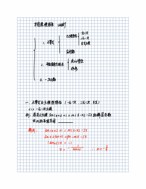
A 的横坐标向左平移1个单位
B的纵坐标向下平移 1个单位
i a1 0 i a 1
i b1 0 b 1
iatb 2
2 对称
pcxgs
①关我对称 lx
gg ② 关利对称 l x
gl ③关于原点对称 l x gl ④ 关于任意点 中点公式
关于谁对称谁不变
0中点公式 liT gg A lxy JBcx gs gyi 20距离公式 A13 11不加了手
解析 pczylsplzy 417 pl 4 pt
样 i 对称诟可得下4.4-y 与 017 灬
到 1 - 4 -4
等-
ixyn
例 3 2 关于11 1 的对称点是
gl 解 没对称点为 lx
笁 X
1 i x -1
9 1 go
i lt 0
ㄑ 132
ˇ 11
先向左移动2个单位
112.1 - 1 1-1.0
个
ulllb at
解析
q 二00 012
00 ÌRP
口pub
4张12 900
0
x
i op岥直⻆三⻆形
fl a tn
i 折叠补充
如图 在直⻆坐标系中 将矩形0ABC站013折叠 使点A落在小1
处 已知0A B AB 1 则A 的坐标是
八
A
OAEOA
C
B i LOAN 300
人十
gl纵轴1 第一象限 十十
② 并且有公共原点 0
③ 两条数轴
第三象限
第四象限 41横轴
一一
一
注意 10单位⻓度可以不统一
竹 ②ㄨ轴 轴上的点 不属于任何象限
2 点的坐标
一
g
- 1、下载文档前请自行甄别文档内容的完整性,平台不提供额外的编辑、内容补充、找答案等附加服务。
- 2、"仅部分预览"的文档,不可在线预览部分如存在完整性等问题,可反馈申请退款(可完整预览的文档不适用该条件!)。
- 3、如文档侵犯您的权益,请联系客服反馈,我们会尽快为您处理(人工客服工作时间:9:00-18:30)。
FX0N-3A模拟量特殊功能模块
一、介绍
FX0N-3A模拟特殊功能块有两个输入通道和一个输出通道,输入通道接收模拟信号并将模拟信号转换成数字值;输出通道采用数字值并输出等量模拟信号。
FX0N-3A的最大分辨率为8位。
在输入/输出基础上选择的电压或电流由用户接线方式决定。
FX0N-3A在PLC扩展母线上占用8个I/O点,8个I/O点可以分配给输入或输出。
所有数据传输和参数设置都是通过应用到PLC中的TO/FROM指令,通过FX0N-3A的软件控制调节的。
PLC和FX0N-3A这间的通信由光电耦合器保护。
上位机PLC的状态改变,模块的运行情况如下:
1、RUN--STOP:在STOP模式期间,保持RUN运行期间模拟输出通道使用的最后一
个操作值。
2、STOP--RUN:一旦上位机PLC切换回到RUN模式,模拟输出就恢复到由程序控
制的正常状态的数字值。
3、PLC电源关闭:模拟输出信号停止运行。
二、性能规格
输入电压输入电流输入
模拟输入范围默认状态,0~10VDC输入选择了0~250范围,如果需要其他电压输入,请重新调整偏置和增益。
0~10V/0~5VDC,电阻200KΩ。
警告:输入电压<-0.5V或>+15V就可能损坏
该模块。
4~20mA,电阻250Ω
警告:输入电流<-2mA或>+60mA就可能损坏
该模块。
数字
分辨率
8bit(位)
最小信号
分辨率
40mV(0~10V/0~250依据输入特性而变)60μA(4~20mA/0~250依据输入特性而变)总精度±0.1V ±0.16mA
处理时间TO指令处理时间×2+FROM指令时间
输入特点
模块不允许两个通道有不同的输入特性
输出 电压输出
电流输出
模拟输出范围 默认状态,0~10VDC 输入选择了0~250范围,如果需要其他电压输入,请重新调整偏置和增益。
0~10V/0~5VDC ,外部负载:1k Ω~1M Ω。
4~20mA ,外部负载:500Ω或更小。
数字 分辨率 8bit(位)
最小信号 分辨率 40mV (0~10V/0~250依据输入特性而变) 60μA (4~20mA/0~250依据输入特性而变) 总精度 ±0.1V
±0.16mA
处理时间
TO 指令处理时间×3
输出特点
如果使用大于8位的数字源数据,则只有低8位的数据有效,高位将被忽略掉。
三、端子接线
模块不允许两个通道有不同的输入特性。
如果电压输入/输出方面出现任何波动或者有过多的电噪音,则要在线路上并上电容器。
A/D OFFSET:输入(模拟量转数字量)偏置校准电位器;
A/D GAIN:输入(模拟量转数字量)增益校准电位器;
D/A OFFSET:输出(数字量转模拟量)偏置校准电位器;
D/A GAIN:输出(数字量转模拟量)增益校准电位器。
四、缓冲存储器的分配(BFM)
缓冲存储器
b8~b15 b7 b6 b5 b4 b3 b2 b1 b0
编号
0 保留通过17#的b0选择的A/D通道的当前值输入数据(以8位存储)
16 保留在D/A通道上的当前值输出数据(以8位存储)
17 保留D/A起运A/D起运A/D通道选择0~15、18~31 保留
BFM0:把外部模拟信号通过转换成数字值后存储在这里。
BFM16:把主机传送过来的数据存储在这里,准备通过转换后输出控制负载。
BFM17:b0=0时选择模拟输入通道1;
b0=1时选择模拟输入通道2;
b1=0--1时,起运A/D转换处理;
b2=0--1时,起运D/A转换处理。
五、校准
1、A/D校准
(1)偏置校准
1)接线:
方法1:(外部输入)
电压电流
方法2:(整数输入)
电压电流
2)输入校准程序:
3)校准过程:
①选择对应的接线方法,使输入的偏置电压/电流符合下表;
模拟输入范围0~10VDC0~5VDC 4~20mADC
偏置校准值0.040V 0.020V 4.064mA
②运行前面程序,确保X0为ON状态;
③调节A/D OFFSET电位器,直到数字值1读入D0为止。
注:顺时针旋转电位器为数字值增加,从最小值到最大值需要转18圈。
(2)增益校准:
校准过程:
①选择对应的接线方法,使输入的增益电压/电流符合下表;
模拟输入范围0~10VDC0~5VDC 4~20mADC
增益校准值10.000V 5.000V 20.000mA
②运行前面程序,确保X0为ON状态;
③调节A/D GAIN电位器,直到数字值250读入D0为止。
注:顺时针旋转电位器为数字值增加,从最小值到最大值需要转18圈。
2、D/A校准
(1)偏置校准
1)接线:
电压电流
2)输入校准程序:
3)校准过程:
①运行前面程序,确保X0为ON状态;
②调节D/A OFFSET电位器,直到仪表显示到相应的偏置电压/电流为止,如下表。
模拟输出范围0~10VDC0~5VDC 4~20mADC
仪表显示值0.040V 0.020V 4.064mA
注:顺时针旋转电位器为数字值增加,从最小值到最大值需要转18圈。
(2)增益校准:
1)输入校准程序:
2)校准过程:
①运行前面程序,确保X0为ON状态;
②调节D/A GAIN电位器,直到仪表显示到相应的增益电压/电流为止,如下表。
模拟输出范围0~10VDC0~5VDC 4~20mADC
仪表显示值10.000V 5.000V 20.000mA
注:顺时针旋转电位器为数字值增加,从最小值到最大值需要转18圈。
六、实例1(FROM / TO):
*FROM指令:
注释:从特殊模块(单元)No.1的缓冲存储器(BFM)29#中读出16位数据传送至上位机PLC 的K4M0中。
*TO指令:
注释:对特殊模块(单元)No.0的缓冲存储器(BFM)12#、13#分别写入上位机PLC中D0、D1的数据。
1、使用模拟输入
2、使用模拟输出
七、实例2(FX0N-3A模拟特殊功能模块专用指令RD3A/WR3A):
*RD3A指令
注释:从处于No.0的FX0N-3A中读出缓冲存储器(BFM)0#的A/D数据传送至上位机PLC 的D0中。
*WR3A指令
注释:对处于No.0的FX0N-3A中缓冲存储器(BFM)16#写入上位机PLC中D1的数据,以便进行D/A转换。
