大宗PCI8402A焊接说明资料
焊接工艺说明书

DATE
APPROVED.BY
日期 DATE
角焊缝 FILLET 角焊缝 FILLET 角焊缝 FILLET
相焊 WELD
WPS NO.
PAGE
2/3
焊接材料 FILLER METALS
焊材类型 TYPE
焊条 ELECTRODE
焊丝 WIRE
焊剂 FLUX
焊材标准 SPEC.
填充金属尺寸 SIZE
焊材型号 CLASSIFICATION
焊材牌号(钢号)BRAND
RANGE
VOLTAGE
(按所焊位置和厚度,分别列出电流和电压范围,记入下表)
FILLIN THE FOLLOWING TABLE WITH APPLICABLE A&V
填充材料
焊接电流
焊道/焊层 WELD LAYER
焊接方法 PROCESS
FILLER METAL
牌号 CLASS
直径 DLA. (mm)
CURRENT
极性
电流
POL. CURRENT(A)
PAGE
3/3
电弧电压 VOLTAGE
(V)
焊接速度 TRAVEL (cm/min)
线能量 HEAT INPUT
(kj/cm)
钨极类型及直径 YUNGSTEN ELECTRODE SIZE AND TYPE 熔滴过渡形式
喷嘴直径(mm): ORIFICE & GAS CUP SIZE 焊丝送进速度(cm/min):
预 热 PREHEAT 预热温度(允许最低值)
PERHEAT TEMP MIN. 层间温度(允许最高值)
INTERPASS TEMP MAX 保持预热时间
PERHEAT MAINTENANGE 加热方式
OME-PCI-1002系列PCI总线A D板产品说明书

16 Differential
Analog Inputs ߜ Sampling Rate:
OME-PCI-1002L: 110KS/s
OME-PCI-1002H: 40KS/s
(Single Channel or
Multiple Channels) ߜ Three Different External
The OME-PCI-1002 includes 16-channels of digital input and 16-channels of digital output. An OME-DB-8025 screw terminal panel can be used to connect
to the digital I/O lines. The OME-DB-16P isolated digital input board and OME-DB-16R relay board can be used to connect the digital I/O on the OME-PCI-1002 to real-world signals.
Outputs: 16 channels; TTL levels Output Low:
VOL = 0.33 V max IOL = 4 mA max Output High: VOH = 3.83 V min IOH = -400 µA max
TIMER COUNTER Internal Pacer Timer: 16-bit, 8 MHz input External Pacer Timer: 16-bit, 8 MHz input Machine Independent Timer: 16-bit, 8 MHz input GENERAL ENVIRONMENTAL Operating Temperature: 0 to 50°C (32 to 122°F) Storage Temperature: -20 to 70°C (-4 to 158°F) Humidity: 0 to 90% RH non-condensing Dimensions: 175 L x 105 mm H (6.9 x 4.1") Power Requirements: 5 V @ 350 mA (max)
PCI-8403硬件说明书

PCI8403简明手册!警告:×接触本采集卡前请确保释放掉身体上的静电,否则静电有可能造成板卡永久性的损坏。
×注意在光隔离用户接口处串入合适的限流电阻后方可加电源,限流电阻不合适会造成板卡的永久损害一、特点与用途●32路光隔离开关量共阴输入●32路光隔离开关量共阴输出●3路光隔离计数输入●光隔离电压500V,占空比50%时,输入开关量频率最大值50K,输出开关量频率最大值10K●全部输出为达林顿输出,每通道可以提供最大100mA的驱动能力●可驱动大功率继电器●使用环境要求:工作温度:0℃~50℃相对湿度:40%~80%存贮温度:-40℃~+85℃外形尺寸: 175.6mm X 98.3mm二、布局图(此布局图中的跳线设置为出厂设置)三、时钟输入源选择(JP1)注:这里的计数器输入和计数器输出与实际的计数器输入和输出有反相关系四、时钟分频输出使能(JP2)跳线标识如图所示,当短接IO一端时,表示端口输出为开关量DO29~DO31 当短接CLK一段时,表示端口输出为计数器所占用。
五、寄存器本卡读写操作为双字(32位)方式六、管脚定义在下列各表中DIx为开关量输入正端,DOx为开关量输出正端DIGNDx为开关量输入负端,DOGNDx为开关量输出负端NC为空管脚,应该保持开路J1DIGND1为J1接口上开关量输入的信号地DOGND1为J1接口上开关量输出的信号地*注意:DIx与DIGND之间加了500欧姆的限流电阻,当输入信号高电平小于6V时可以不接外部限流电阻,否则应该串连限流电阻,保证通过电流处于10mA左右,否则可能会击穿光偶通道,造成板卡损坏J2DIGND2为J2接口上开关量输入的信号地DOGND2为J2接口上开关量输出的信号地OUTx为第x个计数器的输出,与DO29~DO31共用,通过JP2来选择是开关量输出还是计数器输出CLKx为第x个计数器的输入,与DI29~DI31共用七、光偶输入输出基本连接方法本卡的DI0~DI31都是光偶输入的信号正端,DIGND1和DIGND2是信号负端,使用光偶芯片PS2801,用户接线方法见下图:其中Rx是一个限流电阻其选择按照这样的原则:Rx和板卡内部的500欧姆限流电阻可以将流过发光二极管的电流限制在10mA左右。
PCI-8408光隔离开关量输入输出接口卡技术说明书

PCI-8408光隔离开关量输入输出接口卡技术说明书1.概述:PCI-8408开关量输入输出接口卡适用于提供了PCI总线插槽的PC系列微机,具有即插即用(PnP)的功能。
操作系统可选用目前流行的Windows系列、高稳定性的Unix等多种操作系统以及专业数据采集分析系统LabVIEW等软件环境。
在硬件的安装上也非常简单,使用时只需将接口卡插入机内任何一个PCI 总线插槽中,信号电缆从机箱外部直接接入。
为方便我公司原有用户对产品的升级换代,PCI-8408开关量输入输出接口卡的输入输出插座引线定义与PC-6408完全一样。
本卡适用于工业现场中各种开关信号的自动控制以及计算机同数字仪器的接口。
考虑到在开关量的输出中“开/关”瞬态对计算机干扰十分强烈及现场强电的干扰,本卡采用了光电隔离技术,使计算机与现场信号之间全部隔离,提高了计算机与本卡在工作中的抗干扰能力和抗损毁能力。
本卡上的开关量输入为16路(其中前8路具有中断捕获功能),输出为16路,采用两组分别共地方式。
输出部分具有上电后自动清零功能(但主机复位时不清零),并可与我公司研制的PS-002继电器接口板直接配套使用。
2.主要技术指标:2.1输入路数及电气连接方式:16路共地(共阴)方式(其中前8路可采用中断方式)。
2.2输入信号电平范围:TTL~48V。
2.3输入信号电流消耗:≥5mA/每路2.4输出路数及电气连接方式:16路共源(共阳)方式。
2.5输出回路供电要求:+12V~+36V2.6最大输出电流:≤200mA/每路,可直接驱动继电器,但每组总输出电流不应超过2A。
2.7每组信号之间、各组信号与接口卡之间隔离电平:500V。
2.8电源功耗:+5V(±10%)≤400mA2.9环境要求:工作温度:10℃~40℃相对湿度:40%~80%存贮温度:-55℃~+85℃2.10外型尺寸(不含档板):长×高=164.8mm×106.7mm(6.5英寸×4.2英寸)3.工作原理及操作说明:3.1开关量输入部分工作原理:本卡上的所有16路开关量输入信号状态均可以由CPU通过巡检方式读出,即CPU通过直接读取I/O 口上的数据来判断输入信号的状态,其工作原理如图1所示。
PCIe8422使用说明书

北京慧孚达科技有限公司多路RS422/485/232通讯接口卡PCIe8422使用说明书现今社会是飞速发展的信息社会,信息技术对社会发展有着深远影响,而数据采集是信息技术的关键环节。
我公司推出的基于PCI总线、PCIe总线、USB总线及嵌入式等数据采集卡综合了国内外众多同类产品的优点,以其使用的便捷、性能的稳定、性价比高,获得了客户的一致好评,是您理想的选择。
第一节、简介PCIe8422是具有PCIe接口的8路422/485/232接口通讯板卡。
接口类型可以配置成RS232、RS422、RS485任意一种,或者RS232/RS422、RS232/RS485复合类型;可以配置为8路RS422异步接口模式,或配置为4路RS422同步接口模式。
灵活的定制方案,极大限度地满足客户的个性化应用要求。
可广泛用于航天测控、工业测控等系统中。
第二节、板卡性能指标总线接口PCIe,总线宽度x1,支持2.5Gbit/S的双向数据传输速度。
RS422数据传输速率可调节,最高可达4Mbps。
RS485/RS232模式支持异步通讯,RS422模式支持异步、同步通讯。
支持用户自定义波特率。
RS422模式收、发独立,全双工工作方式。
通讯接口起始位、数据位、停止位及校验位均可设置。
每一路422/485/232发送及接收通道都对应有2Kbytes FIFO,用于数据缓存。
板卡有16路数字IO,可扩充为外触发信号。
支持外触发,软触发。
数据接收方式支持查询、中断、DMA方式。
数据发送方式可以单次发送,也可连续发送。
可根据用户需求定制传输协议,如发送时添加帧头、帧尾;接收时检测帧头、帧尾等。
第三节、软件支持PCIe8422多路422通讯卡为客户提供丰富的软件支持, 提供集成软件和驱动程序以及编程接口、动态连接库、使用例程等。
第一节、板卡外形第二节、板卡构造说明1:RS422/485/232外部接口(D型头信号定义,J2)RS422_Tn_N 和 RS422_Tn_P构成第n路RS422输出差分对信号。
AD8402中文资料

REV. 0
Information furnished by Analog Devices is believed to be accurate and reliable. However, no responsibility is assumed by Analog Devices for its use, nor for any infringements of patents or other rights of third parties that may result from its use. No license is granted by implication or otherwise under any patent or patent rights of Analog Devices.
Coefficient Full-Scale Error Zero-Scale Error
N INL DNL ∆VW/∆T
VWFSE VWZSE
VDD = 5 V, VSS = 0 V Code = 80H
Code = FFH Code = 00H
8
Bits
–1.5
+1.5 LSB
–1
+1
LSB
15
ppm/°C
–1.5
LSB
+1.5 LSB
RESISTOR TERMINALS Voltage Range5 Capacitance6 AX, BX Capacitance6 WX Shutdown Current7
Shutdown Wiper Resistance
Common-Mode Leakage
AD5207–SPECIFICATIONS
PCI8002A同步高速数据采集卡硬件操作说明书(doc 32页)(正式版)

PCI8002A 同步高速数据采集卡硬件使用说明书阿尔泰科技发展有限公司产品研发部修订阿尔泰科技发展有限公司目录1PCI8002A 同步高速数据采集卡硬件使用说明书版本:6.1112阿尔泰科技发展有限公司第一章功能概述信息社会的发展,在很大程度上取决于信息与信号处理技术的先进性。
数字信号处理技术的出现改变了信息与信号处理技术的整个面貌,而数据采集作为数字信号处理的必不可少的前期工作在整个数字系统中起到关键性、乃至决定性的作用,其应用已经深入到信号处理的各个领域中。
实时信号处理、数字图像处理等领域对高速度、高精度数据采集卡的需求越来越大。
ISA 总线由于其传输速度的限制而逐渐被淘汰。
我公司推出的基于PCI 总线、USB 总线等数据采集卡综合了国内外众多同类产品的优点,以其使用的便捷、稳定的性能、极高的性价比,获得多家客户的一致好评,是一系列真正具有可比性的产品,也是您理想的选择。
第一节、产品应用本卡是一种基于PCI 总线的数据采集卡,可直接插在IBM-PC/AT 或与之兼容的计算机内的任一PCI 插槽中,构成实验室、产品质量检测中心等各种领域的数据采集、波形分析和处理系统,也可构成工业生产过程监控系统。
它的主要应用场合为:◆电子产品质量检测◆信号采集◆过程控制◆伺服控制第二节、总线及制作工艺特点◆32 位PCI 总线,支持PCI2.2 协议,真正实现即插即用◆支持5V PCI 总线(总线上的+5V 和+12V 均被使用)◆FPGA 接口芯片设计,具有极高的保密性,特别适合OEM 合作第三节、AD模拟量输入功能◆转换器类型:AD9224◆输入量程:±5V、±2.5V、±1V、±0.5V◆转换精度:12 位(Bit)◆采样速率(同步采样)最高采样速率为40MHz(25 纳秒/点)最低采样速率为400KHz(约 2.5 微秒/点)分频公式:采样频率= 主频/ 分频数,其中主频= 80MHz,32 位分频,分频数的取值范围:最低为2,最高为200◆物理通道数:4 通道(各通道完全独立同步采样)◆模拟量输入方式:单端模拟输入◆模拟输入阻抗:>10MΩ◆模拟输入共模电压范围:<±2V◆通道切换方式:4 通道同时转换◆数据读取方式:软件读取方式、DMA 方式(此方式速度最高)◆存诸器深度:每通道512K 字(点)RAM 存储器◆时钟源选项:板内时钟和板外时钟软件可选◆触发模式:软件内部触发和硬件外部触发◆触发类型:边沿触发触发◆触发方向:负向触发、正向触发、负正向触发◆触发电平:共4096 级软件可调,可调范围为±10V1PCI8002A 同步高速数据采集卡硬件使用说明书版本:6.111◆触发灵敏度:软件可选范围为1~65535(819uS)◆模拟量触发源:AI0、AI1、AI2、AI3、ATR、DTR (软件可选)◆系统测量精度:0.1%◆工作温度范围:-40 ~+85℃◆存储温度范围:-40 ~+120℃第四节、DI数字量输入功能◆通道数:8 路◆电气标准:TTL- CMOS 兼容◆最大吸收电流:小于0.5mA(毫安)◆高电平的最低电压:2V◆低电平的最高电压:0.8V第五节、DO数字量输出功能◆通道数:8 路◆电气标准:CMOS 兼容◆最大下拉电流:20mA◆最大上拉电流:2.6mA(毫安)◆高电平的最低电压:3.4V◆低电平的最高电压:0.5V第六节、其他指标◆板载时钟振荡器:80MHz第七节产品安装核对表打开PCI8002A 板卡包装后,你将会发现如下物品:1、PCI8002A 板卡一个2、ART 软件光盘一张,该光盘包括如下内容:a) 本公司所有产品驱动程序,用户可在PCI 目录下找到PCI8002A 驱动程序;b) 用户手册(pdf 格式电子文档);第八节安装指导一、软件安装指导在不同操作系统下安装PCI8002A板卡的方法一致,在本公司提供的光盘中含有安装程序Setup.exe,用户双击此安装程序按界面提示即可完成安装。
APS(AP250)手动反馈焊接铁说明书

INSTRUCTION MANUALAPSStand forAP250 Manual-Feed Soldering IronManual ............................. 1 unit Ref. 0027181Stand for AP250 Manual-Feed Soldering Iron............................................................................... 1 unitThe following items are included:This manual corresponds to the following reference:AP-SFPacking ListStand Cable 1m ............ 1 unit Ref. 0024227Sponge for ModularTool Stands ................... 1 unit Ref. S7034Brass Wool .................... 1 unit Ref. CL62102Features and ConnectionsTo Control UnitWiper forModular Tool StandRef. CL7899AdjustableCable CollectorRef. CC1001Ajustable Tool HolderBrass Wool(inside)Sponge350 mm60 mm80 mm100 mm130 mm130 mmpara manuales - color gris200 mmAdjust the tool holder angle tosuit the work position.Insert the cable into the clip and then insert into the cable collector. Do not leave the cable longer than necessary to reach the work area freely.The cable collector is flexible. It accompanies and adapts to the movements during thesoldering process.The wiper offers different ways to clean the cartridge tips. If desireduse the included sponge.4solder.remaining particles.Tapping Wiping SpongeKeep the sponge damp withThe integrated wiper offers different ways to clean the cartridge tips.50 mm100 mmAccessoriesStand extension cable Ref. A1286Length: 1.5mStand CableMaintenanceBefore carrying out maintenance or storage, always unplug the stand from the station and the tool.- Use a damp cloth to clean the stand. Alcohol can be used only when cleaning the metal parts.- Check periodically that the metal parts of the tool/stand are clean so that the station can check the tool’s status.- Periodically check all cables and tube connections.- Replace any defective or damaged parts. Use original JBC spare parts only.- Repairs should only be performed by a JBC authorized technical service.Clean periodically6Safety- Do not use the stand for any other purpose than soldering or rework.- The power cord must be plugged into approved bases. Be sure that it is properly grounded before use. When unplugging it, hold the plug, not the wire.- Do not work on electrically live parts.- The tool should be placed in the stand when not in use in order to activate the sleep mode. The soldering tip, the metal part of the tool and the stand may still be hot even when the station is turned off. Handle with care, including when adjusting the stand position.- Avoid the contact of flux with skin or eyes to prevent irritation.- Be careful with the fumes produced when soldering.- Keep your workplace clean and tidy. Wear appropriate protection glasses and gloves when working to avoid personal harm.- Utmost care must be taken with liquid tin waste which can cause burns.- This appliance can be used by children over the age of eight and also persons with reducedphysical, sensory or mental capabilities or lack of experience provided that they have been givenadequate supervision or instruction concerning use of the appliance and understand the hazards involved. Children must not play with the appliance.- Maintenance must not be carried out by children unless supervised.750 mm60 mm80 mm130 mm 130 mmpara manuales - color gris200 mmThis product should not be thrown in the garbage.In accordance with the European directive 2012/19/EU, electronic equipment at the end of its life must be collected and returned to an authorized recycling facility.of defective parts and labour.Warranty does not cover product wear or misuse. In order for the warranty to be valid, equipment must be returned, postage paid, to the dealer where it was purchased.0027181-300522APSStand for AP250 Manual-Feed Soldering Iron Ref.: AP-SF- Includes Sleep Mode - Total Net Weight 1462 g / 3.22 lb - Package Dimensions / Weight 342 x 155 x 120 mm / 2022 g (L x W x H) 13.46 x 6.10 x 4.72 in / 4.46 lbComplies with CE standards ESD safeSpecifications。
CSI AL-6XN铸铁焊接建议说明书

AL-6XN alloy is easy to weld using similar parameters as Type 316L stainless steel, including travel speed (IPM) and weld current. It is common to use a weld insert ring for additional alloying when orbital or manual welding in the field.USE WELD INSERT RINGSWhen using weld insert rings for orbital or manual welding, never use filler wire in place of weld insert rings for sanitary tubing. Welding techniques that apply filler wire to the weld face risk the possibility of insufficient alloying in the weld root.The alloy of the insert ring must have a higher molybdenum content than the AL-6XN to compensate for alloy dilution on cooling. Typically, Alloy C-22 (13% Mo) is used. If Alloy C-22 is not available, Alloy 625 (9% Mo) or Alloy C-276 (15% Mo) may be substituted. CSI stocks C-22 weld insert rings.PLACE THE WELD INSERT RING AND FUSION WELDThe weld insert ring should be placed between the two sections and fusion-welded as usual. The weld current must be increased slightly to compensate for increased thickness due to the insert ring.USE INERT GAS FOR WELD COVER AND BACKINGInert gases such as helium may be used, although argon is more common. In some applications, the addition of 3-5% nitrogen to shielding gas can help compensate for the loss of nitrogen during welding.REMOVE HEAT TINTSThe weld heat-affected zone (HAZ) should be no darker than a light straw color. A color-free silver weld and heat-affected zone are best. Any darker weld heat tints must be removed before placing in service. Dark blue and black heat tints are the most susceptible to corrosion. Remove these tints by using abrasives followed by acid cleaningor passivation. A poorly cleaned surface may be just as susceptible to corrosion attacks as the original heat tint.NOTE: When the temperature of the metal is below thedew point, allow it to warm above the condensation temperature to prevent moisture condensate on the surface, which can cause heat tint.WELD INSERT RINGSRING WELDED BETWEEN SECTIONSORBITAL WELD HEAT TINTS REMOVEDWELDING PROCEDURES (WITH FILLER)When welding AL-6XN, metallurgical changes occur in the weld pool that must be considered when developing welding procedures. For most installations of AL-6XN piping systems, the process of post-weld annealing is not feasible. The practice of adding an alloy filler, called over-alloying the weld, is required to improve the corrosion resistance of these welds.Over-alloying replenishes elements in the weld pool that have previously segregated during the melting and re-solidification process. The as-solidified weld has dendrite cores that are depleted of chromium and molybdenum. These elements are essential in the material’s ability to resist localized corrosion attacks. To compensate for the depleted elements, filler metals with high molybdenum content are needed to increase the molybdenum to levels above 6%.CSI evaluated several alloys that could assist in the addition of molybdenum to the weld pool. We found that the 13% molybdenum content of Hastelloy C-22 worked well for over-alloying welds in AL-6XN.AUTOGENOUS WELDING PROCEDURES (WITHOUT FILLER)The as-solidified weld of autogenous welding has dendrite cores that are depleted of chromium and molybdenum. These regions of the weld are more susceptible to localized corrosion; consequently, autogenous welding can be used with the following precautions:• Post-weld heat treatment is required. Anneal temperature above 2150°F (1180°C) followed by rapid cooling in a controlled atmosphere.• The heat treatment duration for annealing must be sufficient to re-homogenize the weld segregation.• Using mixed gases with a nitrogen volume of 3-5% for weld shielding can help improve properties of corrosion resistance.• The ASTM G48-C critical pitting temperature test may be used to assess the quality of autogenously welded and annealed AL-6XN.In the event that neither over-alloying nor heat treatment of the weld occurs, the exposure conditions must be carefully reviewed to determine if autogenous welds are satisfactory. Autogenous AL-6XN welds are more resistant to corrosion than similar welds in types 316L, 317L, and 904L.WELD APPEARANCEWeld appearance can be somewhat misleading when visually compared to hygienic welds made in 316L stainless steel. A typical AL-6XN weld has non-uniform freeze lines and oxide islands in the weld bead. These oxide islands appear as a thin film, having a varying colorwith tints from gray to dark brown that adhere to the surface. The appearance of “light” and “dark” spots on both the inside and the outside of the weld is typical. The heat-affected zone (HAZ) can also have discoloration andis generally a little darker than conventional 316L welds.ACCEPTABLE WELD MADE IN AL-6XN ELECTROPOLISHED TUBINGACCEPTABLE WELD MADE IN AL-6XN MECHANICALLY POLISHED TUBING。
Aseptconn AG 水管焊接指南说明书
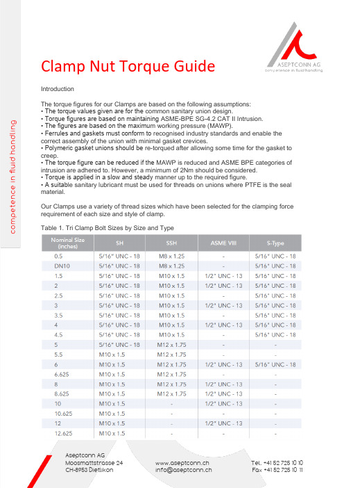
Clamp Nut Torque GuideIntroductionThe torque figures for our Clamps are based on the following assumptions:• The torque values given are for the common sanitary union design.• Torque figures are based on maintaining ASME-BPE SG-4.2 CAT II Intrusion.• The figures are based on the maximu m working pressure (MAWP).• Ferrules and gaskets must conform to recognised industry standards and enable the correct assembly of the union with minimal gasket crevices.• Polymeric gasket unions should be re-torqued after allowing some time for the gasket to creep.• The torque figure can be reduced if the MAWP is reduced and ASME BPE categories of intrusion are adhered to. However, a minimum of 2Nm should be considered.• Torque is applied in a slow and steady manner up to the required figure.• A suitab le sanitary lubricant must be used for threads on unions where PTFE is the seal material.Our Clamps use a variety of thread sizes which have been selected for the clamping force requirement of each size and style of clamp.Table 1. Tri Clamp Bolt Sizes by Size and TypeTable 2. Maximum Torque Figures for Standard Tri Clamp Threaded FastenersTable 3. Torque Conversion FactorsSeals and LubricationSanitary elastomeric seals have very good sealing capabilities and seal at a low clamping force. PTFE does not have these characteristics and the material creep even at lowtemperatures results in a decreased clamping force on the gasket which can produce a leak at a low pressure. Lubrication has a noticeable effect on the pressure holding capability of the clamp unions, specifically when polymeric gaskets are used. Also, when the bolts are unlubricated there is an increased possibility that the threads will gall. Lubricated clamp loads are 46% higher than dry loads. This will allow for a higher force to be imparted onto the polymeric gasket, thus resulting in a more reliable seal.For instance:• A ½” UNC bolt lubricated and tightened to 83.15Nm will apply a clamping load of 1448 Kg. This load will utilise 90% of the bolt yield strength.• A ½” UNC bolt un -lubricated and tightened to 92.7Nm will apply a clamping load of 772 Kg. This load will utilise 40% of the bolt yield strength. In addition to this; as the torque figure is increased, the chances of galling and failure of the eyebolt at the thread root increase. In order to ensure a better lifetime for your acl clamp, torque should be minimised to the correct level. In the event that lubrication cannot be applied to the threads, a suitable bolt /nutmaterial combination should be employed. The standard material for this application would normally be Nitronic 60 (Ref. Tri clamp Anti-Gall).Table 4. Tri Clamp Torque Values – Elastomeric (Dry)Note: Torque values for elastomeric union seals are given as a dry value. The torque value can be kept to a minimum as elastomeric seals are self-energising. In the event that a seal is not achieved, lubrication should be applied to the bolt or a higher torque should be used (donot exceed maximum torque values shown in Table 2).Table 5. Tri Clamp Torque Values – Polymeric (Lubricated)Note: Torque values for polymeric union seals are given as a lubricated value. In the event that a seal is not achieved, lubrication should be re-applied to the bolt or a higher torque should be used (do not exceed maximum torque values shown in Table 2).All technical information and advice given here is based on our previous experiences and/or test results. We give this information to the best of our knowledge, but assume no legal responsibility. Customers are asked to check the suitability and usability in the specificapplication, since the performance of the product can only be judged when all necessary operating data are available. Specifications aresubject to change without notice.。
DIGIPLUS II 焊机使用培训 2015-11
DIGI @PULS II
设备介绍
各种类型的焊丝 •钢 • 不锈钢 • 铝和 铝合金 • 硅铜 • 铜铝 • 药芯焊丝 • 一般的药性焊丝 • 金属芯焊丝 直径为 : 0.6mm、0.8mm、1.0mm、1.2mm、1.4mm、1.6mm
DIGI@PULS II
DIGI@PULS II
DIGIPULS II 一元化程序
FIL Gaz PROCEDE Short arc/lisse spray-modal Pulse Short arc/lisse spray-modal Pulse Short arc/lisse spray-modal Pulse Short arc/lisse Pulse Short arc/lisse
冷双脉冲的优点
在薄金属板上的性能 (没有变形)
基值电流时间 峰值电流时间
减少飞溅 便于操作 焊缝外观
冷双脉冲波
冷双脉冲调节
时间1 (s)= 时间2 (s)
送丝速度 1 (m/mn) /送丝速度 2 (m/mn)
%
基值电流时间 峰值电流时间
DIGI@PULS II
FIL Gaz PROCEDE
SM
-该过渡模式在焊铝时可以大大减少气孔 - 优化焊缝型状,强化机械性能 - 适用于全位置焊
超射流波 ( 30 Hz )
DIGI@PULS II
冷双脉冲 ( CDP )
脉冲波 冷双脉冲
冷双脉冲可以在薄钢板上形成高质量的焊缝,并可防止变 形。冷双脉冲可以形成良好的焊缝外观,适用于焊接超薄 铝板或不锈钢薄板 (< 2mm)。
DIGIPULS II 一元化程序
Miller 334 771- -001 9611A22 焊接工具简易操作手册说明书

Simplified service manualLIST OF CONTENTS Page ........................................................... SAFETY4.......................................... TECHNICAL DESCRIPTON5 ..................................................... INSTALLATION6 ....................................................... OPERATION10 .................................................... MAINTENANCE10................................................. SELECTION TABLE11......................... ACCESSORY SET FOR INTERNAL WELDING12................. ACCESSORY SET FOR EXTERNAL FILLET WELDING13......................... ACCESSORY SET FOR WELDING TITANIUM14 WORKING RANGE15.............................................................................................. DIMENSION DRAWING16 ......................................................... DIAGRAM17........................................... CONNECTION DIAGRAM18....................................... SPARE PARTS LIST A22POB21 Rights reserved to alter specifications without noticeSAFETYSAFETYUsers of ESAB welding equipment have ultimate responsibility for ensuring that any-one who works on or near the equipment observes all the relevant safety precau-tions.Safety precautions must meet the requirements that apply to this type of welding equipment.The following recommendations should be observed in addition to the standard re-gulations that apply to the work place.All work must be carried out by trained personnel who are familiar with the operation of the welding equipment.Incorrect operation of the equipment may lead to a hazardous situation which can result in injury to the operator and damage to the equipment.1.Anyone who uses the welding equipment must be familiar with:S its operationS the location of emergency stopsS its functionS relevant safety precautionsS weldingTo make this easier each switch,pushbutton or potentiometer is marked with a symbol or text that indicates its function when activated.2.The operator must ensure that:S no unauthorized person is stationed within the working area of the equipment when it is started up.S that no--one is unprotected when the arc is struck3.The work place must:S be suitable for the purposeS be free from draughts4.Personal safety equipmentS Always wear recommended personal safety equipment,such as safety glasses,flame--proof clothing,safety gloves.S Do not wear loose--fitting items,such as scarves,bracelets,rings,etc.,which could become trapped or cause burns.5.General precautionsS Make sure the return cable is connected securely.S Work on high voltage equipment may only be carried out by a qualified electrician.S Appropriate fire extinquishing equipment must be clearly marked and close at hand.S Lubrication and maintenance must not be carried out on the equipment dur-ing its operation.TECHNICAL DESCRIPTIONThe POB tube plate welding tool is intended for TIG--welding of tubes into flat tube plates. It is suitable for all types of weld joints,in certain cases using extra equipment.The POB12--60welding tool is intended for use together with a spindle and a centering mandrel according to the selection table on page11.POB12--60is intended for use with the power sources MECHTIG315INVERTER, PROTIG315INVERTER,PROTIG250and PROWELDER250TECHNICAL DATA A22POBMax.continuous welding current180A/60%Max.pulsed welding current200A/60%Working range:base specificationwith titanium welding kitwith external fillet welding kitwith internal welding kit12--60mm12--60mm12--60mm according to designationElectrode angle for:butt weldinginternal fillet weldingexternal fillet weldinginternal welding(See page15) parallel with tube axis 30_to tube axis15_to tube axis90_to tube axisElectrode diameter 1.6and2.4mm Speed of rotation0.3--4.5r.p.m Wire feed speed0.15--1.5m/min Wire diameter0.8and0.91mm Length of welding cable8mWeighttoolcable and hose bundle 4.5kg4.5kgOrder no.POB12--60,base version with wire feed unit333893--881Base version can be fitted with accessory kits for -external fillet welding-titanium welding-internal welding diameter:9.5--15mm15--20mm20--30mm333897--880441000--880441131--880441132--880441133--880 dra1b003When ordering an accessory set for internal welding,please indicate both the inner diameter (D)of the tube and the distance of the welding joint to the outside(A)of the plate.INSTALLATION1.Welding power source,see separate instruction manual.2.Dimension drawing,see page16.3.Diagram,see page17.4.Connection diagram,see page18and page19.5.Tool dismantling:It is necessary to dismantle the tool.S For adjustment of the”home”position.S In the event of a fault.Dismantling:S Remove the three bolts(1)in the support ring(2).S Remove the screw(4).S Pull off the support tube(3).S Carefully withdraw the entire inner assembly(5)backwards,being careful not to damage the microswitch.6.Adjusting the”home”position:S Remove the four bolts(7).S Withdraw the gear ring.The lifting cog influencing the microswitch can now be moved a full turn in22˚,5steps,starting at11˚,25counted from12o’clock.7.Tool reassembly:S Insert the inner assembly(5)in the outer casing(6).Make sure that the microswitch is not located just opposite the lifting cog.S Rotate the parts slightly relative to one another,so as to engage the motordrive gear and the gear ring.S Fit the support tube(3),(lightly grease the contact surface of the sealing ring with a suitable grease,e.g.Barrierta).Fit the support plate(2)with the screws(1).S Fit the screw(4).8.Replacement and fitting of the electrode:S Cut off the electrode to some45mm and grind it to the desired angle.S Remove the gas cup(3).S Remove the electrode nozzle(2)and the electrode nozzle with gas lens.S Replace the electrode.When changing to a different electrode diameter it is necess-ary also to change the electrode nozzle(2)and the collet(1).dra1b001The adjustment of the electrode is important to guarantee the repeatability for continued welding.Use ready--ground electrodes of the same length and fit them in the same position.9.Adjustment of the welding diameter:S Slacken the locking screw(8).S Use a screwdriver to turn the gear wheel(7),which is mounted on the link arm(3),sothat the correct welding circle diameter isobtained.S Slacken the screw(4).S Adjust the electrode angle by rotatingthe electrode holder(6).S Tighten the locking screws(4and8).10.Adjusting the arc length:S Adjust the length of the arc(i.e.thedistance between the tip of theelectrode and the workpiece)byscrewing the spacing tube(9)in or out.S Secure the setting by means of thelocking nut(10).11.Inserting the filler wire:S Cut off any bent length of the wireand file off the end.S Feed the wire into the nozzle.S Advance the wire through the tool(by running the feed unit manually).12.Replacing the wire nozzle:S Undo the screw(5)and remove the nozzle,which is threaded on to the wire guide.13.Replacing the wire guide:S Dismantle the tool.S Remove the wire nozzle from the wireguide and remove the wire guide from theinner part of the tool.S Screw the internally bevelled end of thenew wire guide into the feed unit.S Fit the wire nozzle.S Mount the tool.dra1b002OPERATIONThe POB tube welding tool connected to the programmable welding power source PROTIG 250,PROWELDER 250,PROTIG 315INVERTER or MECHTIG 315INVERTER:S Set all the welding parameters on the programmable PROTIG 250,PROWELDER 250,PROTIG 315INVERTER or MECHTIG 315INVERTER power source unit.S Adjust the position and the angle of the electrode.SStart the automatic welding sequence by pressing the ”Start”button on the power source or directly on the POB tube welding tool.dra1b004It is important that the tool is suspended according to the adjoining figure.For balancing to weightlessness a counterbalancing device is used.Ordering number 332330--005MAINTENANCES Clean the tool as necessary.S Check wearing parts at regular intervals and replace as necessary.S Check that all hoses and connections for gas,water,welding current and control current are undamaged and correctly connected.SCheck that the correct electrode is being used and that it is properly ground.By separating the inner and outer parts from each other the equipment is easy to service.SELECTION TABLETube diameter Centering mandrel Spindle Min.mm Max.mm Ordering no.Ordering no.9,910,5442634--880442714--880 10,310,9442634--88110,711,3442634--88211,111,7442634--88311,512,1442634--88411,912,7442634--88512,513,3442634--88613,113,9442635--880332208--880 13,714,5442635--88114,315,4442635--88215,216,3442635--88316,117,6442635--88417,419,0442635--88518,820,2442635--88619,921,7442635--88721,423,2442636--880332209--880 22,924,7442636--88124,426,6442636--88226,328,5442636--88328,130,7442636--88430,333,1442636--88532,736,7442636--88636,240,1442636--88739,643,7442637--880332210--880 43,247,3442637--88146,751,8442637--88251,257,2442637--88356,663,7442637--88463,071,4442637--88570,679,0442637--88678,286,6442637--887ACCESSORY SET FOR INTERNAL WELDINGOrder number,see on page5.Fitting:1.Dismount the support plate01and the support tube02.2.Pull of the envelope of the tool06.3.Slacken the welding cable clamp07(approx.6turns)and remove the screws03och04.4.Pull out the electrode holder and link arm05far enough to allow the welding cable to bedisconnected from the electrode holder.5.Push back the envelope06and the support tube02.6.Connect the accessory set for internal welding08to the welding cable.7.Pull the accessory set into the correct position by means of the welding cable and secureit.8.TIGHTEN THE WELDING CABLE CLAMP07THROUGH HOLE09IN THEOUTER CASING06,OTHERWISE THE ROTATION MOTOR WILL BE DAM-AGED!dra1b013ACCESSORY SET FOR EXTERNAL FILLET WELDINGOrder number,see on page5.Fitting:1.Dismount the spacer tube.2.Rotate the inner portion,so that the cable is just opposite the group of holes2xø8in the envelope.3.Insert a2.5mm Allen key through the holesø8and slacken the welding cable clamp(approx.6turns).4.Dismount the electrode holder and pull it out.5.Replace the electrode holder and pull into correct position by means of the welding cable.6.TIGHTEN THE WELDING CABLE CLAMP THROUGH THE HOLESø8.OTHERWISE THE ROTATION MOTOR WILL BE DAMAGED!7.Fit the guide finger mount,the guide fingers,then Allen screw and the locking washer.8.Replace the electrode nozzle.cra1b014ACCESSORY SET FOR WELDING TITANIUMOrder number,see on page5.Welding with the accessory kit for titanium.1.Cut a hole in the rubber disk(1)so that the rubber rests against the plate at a safe dis-tance from the arc.2.Dismount the complete gas shield(2)from the three--point support(3)by means of anAllen key(4).3.Adjust the weld diameter and arc length in the normal way(preferably while the tool isattached to the work piece).4.Fit the gas shield(2)with the gas connection pointing downwards.5.Purge the tool with gas to drive out all the air.6.Tape over theø8holes in the outer casing of the tool(6).dra1b015。
ORBIMAT CA 自动焊接系统说明书
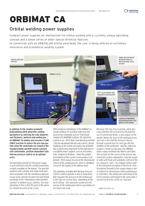
ORBITALUM TOOLS GMBH A BRAND OF ITW ORBITAL CUTTING & WELDING7ORBIMAT CAIn addition to the reliable automatic programming which generates welding parameters by entering the tube diameter, wall thickness, material and welding gas all O RBIMAT CA models also include a FLOW FORCE function to reduce the pre-flow gas time when the weld heads are closed in the standard model and BUP control function with controllable, position-dependent tube internal pressure control as an optional extra.The operating concept for the power supply is quite different from the standard operating variants available on the market: The operator guidance with a display and single-knob oper-ation originates from the automotive manufac-turing sector and has become tried and tested worldwide in the "information entertainment systems" in modern luxury vehicles. The main advantage of this is that the gaze of the opera-tor remains focused on the screen.Other technical refinements of the ORBIMAT CA include softkeys for essential, high-level and quick-action commands such as "Start/Stop". Compared to WINDOWS systems, the operating system in use – RTOS (Real Time Operating System) – has the advantage that not even a direct, abrupt shutdown of the system will lead to any problems. This is particularly important for the operation of susceptible power supplies, such as on building sites. Compare to Windows – where the graphic presentation of the current screen window is im-portant – RTOS always focuses on the steering and control of the welding process, which is ultimately crucial for the quality of the welding result.The optionally available BUP (Backup Pressure Control) control upgrade is also an innovation. BUP regulates the pressure of the forming gas in the tube on a sector basis, depending on the torch setting – this operation counteracts the gravity of the welding pool and so guarantees an all-round even seam.Moreover, the Flow Force function, which deci-sively shortens the work process through the use of closed weld heads, is also unique on the market. Before the start of the welding process, inert gas is fed from the pressure reducer through a second duct for inert gas into the chamber of the weld head – and the undesired oxygen is rinsed out abruptly; the ORBIMAT power supply automatically detects and takes into account for the course of the process any connected system components, from the sealed or open weld head with automatic control of the arc clearance* (AVC = Arc Voltage Control) and/or the integrated oscillation of the torch* (OSC = Oscillation) through to the oxygen analysis unit. In contrast to conventional orbital welding pow-er controllers, the setting and controlling of the torch clearance with regard to the weld seam is carried out directly via the arc clearance.* ORBIMAT 300 AVC/OSC onlyCompact power supplies for mechanized TIG orbital welding with a currently unique operating concept and a whole series of other special technical features.In connection with an ORBITALUM orbital weld head, the user is being offered an extremely innovative and economical welding system.Orbital welding power suppliesSimple and convenient operation thanks to multifunctional rotary actuatorIntuitive operator interfaceAutomatic programming and multilingual menu navi-gation via color display10.5" swivel monitor and integrated system printerORBIMAT 165 CAORBIMAT 300 CAORBITALUM TOOLS GMBH Josef-Schuettler-Str.1778224SingenGermanyTel.+49(0)7731792-0Fax+49(0)******************************A BRAND OF ITW ORBITAL CUTTING & WELDING 8= feature included= feature not included* = DC welding onlyThe technical data are not binding. They are not warranted characteristics and are subject to change. Please consult our general conditions of supply.。
MOXA CP-132EL系列2口RS-422 485PCI表达板说明书

CP-132EL Series2-port RS-422/485PCI Express boards with optional2kV isolationFeatures and Benefits•PCI Express1.0compliant•921.6kbps maximum baudrate for fast data transmission•128-byte FIFO and on-chip S/W flow control•Low-profile form factor fits small-sized PCs•Drivers provided for a broad selection of operating systems,includingWindows,Linux,and UNIX•Easy maintenance with built-in LEDs and management softwareCertificationsIntroductionThe CP-132EL Series of2-port PCI Express boards are designed for industrial automation applications that require a long-distance,multipoint,PC-based data acquisition solution.RS-485Multidrop for up to31Devices Within1.2kmThe CP-132EL Series boards have two RS-422/485serial ports,each of which can achieve data rates up to921.6kbps.In RS-485mode,the boards can connect up to31daisy-chained RS-485devices within a range of1.2km.For long-distance RS-485communication,choose the CP-132EL-I model,which comes with2kV electrical isolation protection to prevent equipment damage.Drivers Provided for Windows,Linux,and UNIXMoxa continues to support a wide variety of operating systems,and the CP-132EL Series is no exception.Reliable Windows and Linux drivers are provided for all Moxa boards,and other operating systems,such as WEPOS,are also supported for embedded integration.SpecificationsSerial InterfaceComm.Controller16C550C compatibleBus PCI Express1.0Connector DB25femaleFIFO128bytesMax.No.of Boards per PC8No.of Ports2Serial Standards RS-422,RS-485Baudrate50bps to921.6kbps(supports non-standard baudrates)Data Bits5,6,7,8Stop Bits1,1.5,2Parity None,Even,Odd,Space,MarkFlow Control None,XON/XOFFIsolation CP-132EL-I-DB9M:2kVSerial SignalsRS-422Tx+,Tx-,Rx+,Rx-,GNDRS-485-4w Tx+,Tx-,Rx+,Rx-,GNDRS-485-2w Data+,Data-,GNDSerial Software FeaturesWindows Drivers DOS,Windows95/98/ME/NT/2000,Windows XP/2003/Vista/2008/7/8/8.1/10(x86/x64),Windows2008R2/2012/2012R2/2016/2019(x64),Windows Embedded CE5.0/6.0,Windows XP EmbeddedLinux Drivers Linux kernel2.4.x,Linux kernel2.6.x,Linux kernel3.x,Linux kernel4.x,Linux kernel5.x UNIX Drivers Solaris10,UnixWare7,SCO OpenServer5,SCO OpenServer6,QNX6Power ParametersInput Current CP-132EL-DB9M:548mA@3.3VDCCP-132EL-I-DB9M:636mA@3.3VDCPhysical CharacteristicsDimensions CP-132EL-DB9M:67.21x101.97mm(2.65x4.08in)CP-132EL-I-DB9M:67.21x103.97mm(2.65x4.16in)LED InterfaceLED Indicators Built-in Tx,Rx LEDs for each portEnvironmental LimitsOperating Temperature0to55°C(32to131°F)Storage Temperature(package included)-20to85°C(-4to185°F)Ambient Relative Humidity5to95%(non-condensing)Standards and CertificationsEMC EN55032/35EMI CISPR32,FCC Part15B Class BEMS IEC61000-4-2ESD:Contact:4kV;Air:8kVIEC61000-4-3RS:80MHz to1GHz:3V/mIEC61000-4-4EFT:Power:1kV;Signal:0.5kVIEC61000-4-5Surge:Power:2kVIEC61000-4-6CS:150kHz to80MHz:3V/m;Signal:3V/mIEC61000-4-8PFMFDeclarationGreen Product RoHS,CRoHS,WEEEMTBFTime CP-132EL-DB9M:4,147,133hrsCP-132EL-I-DB9M:1,681,099hrsStandards Telcordia(Bellcore)Standard TR/SRWarrantyWarranty Period5yearsDetails See /warrantyPackage ContentsDevice1x CP-132EL Series serial boardDocumentation1x quick installation guide1x warranty cardDimensionsCP-132EL CP-132EL-IOrdering InformationModel Name Serial Standards No.of Serial Ports Isolation Included Cable CP-132EL-DB9M RS-422/4852–CBL-M25M9x2-50 CP-132EL-I-DB9M RS-422/48522kV CBL-M25M9x2-50 Accessories(sold separately)ConnectorsMini DB9F-to-TB DB9female to terminal block connectorCablesCBL-M25M9x2-50M25to2x DB9male serial cable,50cm©Moxa Inc.All rights reserved.Updated Sep24,2021.This document and any portion thereof may not be reproduced or used in any manner whatsoever without the express written permission of Moxa Inc.Product specifications subject to change without notice.Visit our website for the most up-to-date product information.。
Thermal Arc Fabricator 211i 多功能焊接设备说明书
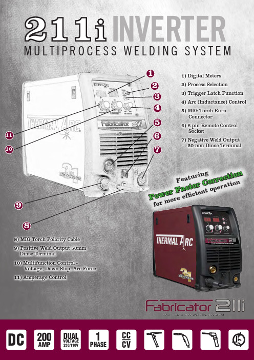
1)Digital Meters 2)Process Selection 3)Trigger Latch Function 4)Arc (Inductance) Control 5)MIG Torch Euro Connector 6)8 pin Remote Control Socket 7) Negative Weld Output50 mm Dinse Terminal75826143 INVERTERM U L T I P R O C E S S W E L D I N G S Y S T E M109118)MIG Torch Polarity Cable 9)Positive Weld Output 50mm Dinse Terminal 10)Multifunction Control -Voltage, Down Slop, Arc Force 11)Amperage ControlF ea tu r i n g P o w e r F a c t o r C o r r e c tio n f o r mo r ee f fi c i e n t o p er a t i o nThe Thermal Arc Fabricator 211i is a dual-voltage, full multi process, digital control, DC, CC/CV, MIG/Stick/Lift TIG inverter power supply designed for precision MIG, DC TIG and Stick welding. This unit is equipped with an integrated wire feed unit, voltage reduction device (applicable in stick mode only), power factor correction, digital voltage and amperage meters and a host of other features in order to fully satisfy the broad operating needs of the modern welding professional.Three Process Capability:MIG (GMAW/FCAW), STICK (SMAW), TIG (GTAW).MIG:V I nfinite Voltage Control with optimized starting performance.V I nductance Control for arc stability and spatter control.V T weco MIG Gun with 3m cable and industry standard Euro connection.V D urable Metal Feed Plate features 2 roll drive system, quick change reversible drive rolls and easy-to-set single scaled wire tension knob.V 100, 200, or 300mm Spool Capacity allows easy installation of wire spool sizes.V S pool Gun ready.STICK: V A djustable Arc Force Control for optimum STICK electrodeperformance.TIG:V L ift TIG Start: Provides TIG arc starting without use of high frequency.Other Features:V D ual Voltage: 230V Input allows up to 210A welding output for use in workshops. 110V Input allows up to 140A welding output for on-site work.V P FC Power Factor Correction: Up to 40% more electrically efficient than conventional MIG Welders.V D igital Meters: Voltage and Amperage meters.V E xcellent Portability: Lightweight, only 26kg.V C omprehensive Setup Chart: Weld set up guide for optimumwelding performance over a wide range of materials and shielding gases.V T rigger Control: 4T (Latch) eliminates operator fatigue.V R emote Receptacle: Enables connection of remote control devices and Spool Gun. (Remote function not available in Stickmode.)V Q uick Change Polarity: Simple quick change polarity (notools required) from the front of the power source.V O verload Protection: Shuts down the power source to protect the internal electrical components from overheating.V I P23S: Suitable for outdoor use.Control PanelMIG Gun / Spool Gun Switch MIG Gun Euro Connection 8 pin Remote Receptacle for remote devices & Spool GunHeavy Duty Welding output terminals with polarity reversal capability Local/Remote Switch Burnback Control Easy installationWire Spool Adaptor & Braking SystemMetal 2 Roll wire drive system with quick change drive rolls and single tension armComprehensive Welding Setup Chart for welding process parametersSYSTEM FEATURESCONTROL PANELPower Indicator The Green power indicator illuminates in the presence of power on the control circuitry Digital Meters WFS / AMPS and Volts Left KnobAdjust weld Process value •MIG - Wirefeed speed •TIG - Amperage •STICK - Amperage Middle KnobVoltage, down slop and arc force controlFault IndicatorThe Fault will illuminate yellow when any of the faults are detected Process Mode Button Depress to change process:•MIG (GMAW/FCAW)•TIG (GTAW)•STICK (SMAW)Trigger Latch Button Depress to change Trigger Fn:• 2T (On/Off)• 4T (Trigger Hold)- O nce the weld arc has started, release the trigger and continue welding - A ctivate the trigger again or brake the welding arc to finish weldingRight KnobArc (Inductance) controlPower SourceWork CableElectrode HolderDrive RollsShield Gas HoseTweco MIG GunPart W1004207 - includes:Tweco WeldSkill 220A MIG Gun (10ft / 3m) WS220XE-10-3035Tweco WeldSkill 220A MIG Gun (12ft / 4m) WS220XE-12-3035Tweco TWE2 250A MIG Torch with 3m cable 161.550.307Tweco TWE2 250A MIG Torch with 4m cable 161.550.40726V TIG Torch (4m)310.090.001Spool Gun (required for aluminium welding) SG160XTA12-3035Basic Utility CartW4014700Single Cylinder Professional Cart W4015001Dual Cylinder Professional Cart W4015002Consumables Storage Box 872726Remote Foot Control, 7.6m 10-4016Tweco WeldSkill Helmet WHF41001Replacement Gas HoseW7004930Single Cylinder Cart Dual Cylinder CartFeed Roll 0.6/0.8mm V groove (hard), (fitted) 62020Feed Roll 0.9/1.2mm V groove (hard) 62022Feed Roll 0.8/0.9mm U groove (soft) 62179Feed Roll 1.0/1.2mm U groove (soft)62024Feed Roll 0.8/0.9mm V knurled (flux cored)62028•Fabricator 211i Power Source •Tweco MIG Gun (3m)•Feed Roll 0.6/0.8mm V groove (hard)•Electrode Holder with lead (4m)•Work Clamp with lead (4m)•Shield Gas Hose assembly •Operating Manual。
焊接机器人说明书
绪论1946年第一台电子计算机的问世以后,使得机器人这个概念有了从戏剧走向现实的可能,随着大批量生产以及恶劣条件对自动化程度高的操作机械的迫切需求,1954年,美国的戴沃尔最早提出了工业机器人的概念,并申请了专利。
该专利的要点是借助伺服技术控制机器人的关节,利用人手对机器人进行动作示教,机器人能实现动作的记录和再现。
这就是所谓的示教再现机器人,现有的机器人差不多都是采用的这种控制方式。
现今,工业机器人的概念是指由操作机(机械本体)、控制器、伺服驱动系统和检测传感装置构成,是一种仿人操作、自动控制、可重复编程、能在三维空间完成各种作业的机电一体化生产设备。
按照机器人从低级到高级的发展程度,可以把机器人分成三代。
第一代机器人,主要指只能以“示教—再现”方式工作的机器人。
这类机器人的本体是一直类似于人的上肢功能的机械手臂,末端是手爪等操作机构。
第二代机器人,是指基于传感器来工作的机器人。
它依靠简单的感觉装置获取作业环境和对象的简单信息,通过对这些信息的分析、处理,做出一定的判断,对动作进行反馈控制。
第三代机器人,既智能机器人,这是一类具有高度适应性的有一定自主能力的机器人。
目前世界上90%以上的工业机器人都属于第一代机器人。
真正具有只能的、理想的、完整的智能机器人目前还处在研究阶段。
本次设计的焊接机器人也属于第一代机器人,设计其腰部的回转台和内部系统。
1 传动装置的分析及确定由题目分析得,焊接机器人的腰部做回转运动。
本方案是大齿轮与机器人底座由螺栓固定在一起,小齿轮与大齿轮啮合,并带动转台做回转运动,电机相对于转台静止。
见图1-1。
本系统由电动机提供动力,由谐波减速器减速,带动小齿轮绕固定的大齿轮做回转运动。
图1-1 箱体内部传动简图1—电动机;2—谐波减速器;3—小齿轮;4—大齿轮已知条件为:焊接机器人腰部底座高300mm,大臂长1000mm,转轴位置在高600mm处,直径200mm,小臂长1500mm 处,转轴在300mm处,直径150mm。
IPC-SM-840D永久性阻焊的鉴定和性能译稿
Qualification and Performance Specification ofPermanent Solder Mask2010年3月IPC(中文版)标准前言本标准翻译采用2007年4月的IPC-SM-840D《永久性阻焊剂的鉴定和性能》(英文版)目的是为永久性阻焊剂提供详细的性能判别准则。
在CPCA标准化工作委员会的组织下,本公司对IPC-SM—840D进行了翻译和修订,形成本标准的初稿.继而在CPCA标准化工作委员会中进行讨论并征集了广大CPCA会员的意见后,完成本标准。
本标准由中国印制电路行业协会标准化工作委员会提出本标准由中国印制电路行业协会(CPCA)归口本标准负责单位:深圳市容大电子材料有限公司目次1 范围和设计 (1)1。
1 范围 (1)1。
2 目的 (1)1.3等级 (2)1。
4声明 (2)1。
5术语和定义 (2)1.5。
1 AABUS(供需双方商定) (2)1。
5.2起泡 (3)1。
5.3粉化(固化阻焊层) (3)1.5。
4 颜色变化(固化阻焊层) (3)1。
5.5 CoC(合格证) (3)1.5。
6微裂纹(敷形或者阻焊层覆膜) (3)1.5。
7 分层(固化阻焊层) (3)1。
5。
8 FTIR (3)1.5。
9 液化(固化阻焊层) (3)1.5.10 剥离(固化阻焊层) (3)1。
5.11 SAC 305 (3)1。
5.12 软化(固化阻焊层) (4)1。
5。
13 阻焊层 (4)1。
5.14膨涨(固化阻焊层) (4)1.5.15粘性 (4)1.5。
16芯吸作用(阻焊层) (4)2 引用文件 (4)2。
1 IPC1 (4)2。
2美国安全检测实验室(UL)4 (5)2。
3美国材料及试验协会(ASTM)5 (5)3 要求 (6)3.1 鉴定/符合性 (6)3。
1.1 材料鉴定和符合性 (6)3。
1.2 印制板过程鉴定和评估 (6)3。
1。
3再鉴定 (6)3.2 材料 (6)3。
焊接工艺卡片,评定设计

焊接说明书和记录卡(WIR)WIR编号:说明书名称所应用的WPS编号被采用的焊缝编号焊缝数量母材牌号及规格焊接方法接头及坡口形式见简图焊接位置焊接材料牌号焊条:点焊焊丝:焊剂:工艺要求预热温度℃/ 坡口加工方法和清理层间温度℃清根方式后热温度及时间℃×h / 焊缝外形要求焊后热处理及无损探伤检查焊后热处理无损探伤检测超声波探伤% √射线探伤% √磁粉探伤% √着色探伤% √焊接记录焊缝层数焊接方法焊接牌号、直径(mm)焊接电流(A)焊接电压(V)焊接速度(m/h)里面外面焊接质量检查点焊前检查要求焊中检查要求焊后检查要求焊工资格√层间温度√后热温度及时间/ 焊材牌号及规格√焊接规范√焊缝表面质量√焊材烘干及清理√反面清根后检查√磁粉探伤或着色探伤/ 装配尺寸/ 超声波或射线探伤√坡口清理√焊缝硬度控制/坡口处磁粉探伤或着色探伤/ 焊工钢印√坡口边缘钢板探伤/焊接接头简图备注编制日期审核焊接工艺指导说明书(WPS)WPS编号:焊接方法焊接位置接头型式基本金属牌号规格相当类别相当组别焊接材料焊条型号规格焊丝牌号规格焊剂焊接工艺要求预热温度℃层间温度℃焊后保温温度及时间℃×h焊后热处理预热温度℃保温时间h 冷却方式技术要求坡口加工焊前清理层间清理清根方式多层或单层摆动或不摆动接头尺寸简图焊接规范要求层次焊接工艺焊接规范电源种类及极性焊接电流(A)焊接电压(V)焊接速度(m/h)最大线能量(KJ/cm)干伸长度(mm)设备型号MZ-1000评定要求按JB4708-2000规定,评定内容如下:1.外观检查2.无损检测(射线、超声波探伤)3.力学性能检验(拉、弯、冲击)编制日期审核。
- 1、下载文档前请自行甄别文档内容的完整性,平台不提供额外的编辑、内容补充、找答案等附加服务。
- 2、"仅部分预览"的文档,不可在线预览部分如存在完整性等问题,可反馈申请退款(可完整预览的文档不适用该条件!)。
- 3、如文档侵犯您的权益,请联系客服反馈,我们会尽快为您处理(人工客服工作时间:9:00-18:30)。
大宗物料软件PCI8402A焊接资料(中天内部)
本图为河北旭阳2011物流自动化项目的焊接图,本文以此为例:
硬件:5V电源2个,18V电源1个,PCI8402A接头1个
2011河北旭阳物流自动化PCI8402A接口示意图,读图解析:
网线内8根线,用到6根分别是:棕色、棕白色、橙色、橙白色、绿色、绿白色,其中棕色与棕白色接18V电源的负极(一般为黑色,可用万能表现场测量下),橙色与橙白色接18V 电源的正极(一般为红色,可用电能表现场测量下),绿色接5V电源的正极(一般为带字的,可用万能表现场测量下),绿白色接PCI8402A的接口如图(35),5V电源的负极接PCI8402A 的接口如图(21)。
如此整个接头串联完成。
软件:1、安装驱动;2、进入大宗物料,点击初始-监控设备配置,勾选上启用红外监磅仪,调试通道接口参数(详见PCI8402A调试资料),选择I/O卡为PCI8402A,如图1:
图1
操作主要步骤:
1、布线
2、焊接PCI8402A接口
3、插上PCI8402A主板,并安装驱动
4、插上焊好的PCI8402A接头,勾选选项调试参数
注意:
1、布线时只用到一根网线,在接收端将线剪断,其中一端通向红外发射端,另一端焊接
PCI8402A接口。
2、焊接时注意正负极,若短路会将PCI8402A烧毁
3、插上PCI8402A启动时第一次会自动弹出安装驱动向导,可根据向导安装然后重启
4、勾选参数时可根据红外说明书进行调试,说明书详细说明各针参数,可根据实际选择的
针选择参数,务必将I/O卡勾选上相同型号参数,否则系统没有反应
附图:
附图
附件:PCI8402A/B光隔离开关量输入继电器输出接口卡简明手册(直接百度)。
