Velocity and density spectra of the Small Magellanic Cloud
Principles of Plasma Discharges and Materials Processing第3章
CHAPTER3ATOMIC COLLISIONS3.1BASIC CONCEPTSWhen two particles collide,various phenomena may occur.As examples,one or both particles may change their momentum or their energy,neutral particles can become ionized,and ionized particles can become neutral.We introduce the funda-mentals of collisions between electrons,positive ions,and gas atoms in this chapter, concentrating on simple classical estimates of the important processes in noble gas discharges such as argon.For electrons colliding with atoms,the main processes are elastic scattering in which primarily the electron momentum is changed,and inelas-tic processes such as excitation and ionization.For ions colliding with atoms,the main processes are elastic scattering in which momentum and energy are exchanged, and resonant charge transfer.Other important processes occur in molecular gases. These include dissociation,dissociative recombination,processes involving negative ions,such as attachment,detachment,and positive–negative ion charge transfer,and processes involving excitation of molecular vibrations and rotations. We defer consideration of collisions in molecular gases to Chapter8.Elastic and Inelastic CollisionsCollisions conserve momentum and energy:the total momentum and energy of the colliding particles after collision are equal to that before collision.Electrons and fully stripped ions possess only kinetic energy.Atoms and partially stripped ions have internal energy level structures and can be excited,de-excited,or ionized, Principles of Plasma Discharges and Materials Processing,by M.A.Lieberman and A.J.Lichtenberg. ISBN0-471-72001-1Copyright#2005John Wiley&Sons,Inc.43corresponding to changes in potential energy.It is the total energy,which is the sum of the kinetic and potential energy,that is conserved in a collision.If the internal energies of the collision partners do not change,then the sum of kinetic energies is conserved and the collision is said to be elastic.Although the total kinetic energy is conserved,kinetic energy is generally exchanged between particles.If the sum of kinetic energies is not conserved,then the collision is inelas-tic.Most inelastic collisions involve excitation or ionization,such that the sumof kinetic energies after collision is less than that before collision.However,super-elastic collisions can occur in which an excited atom can be de-excited by acollision,increasing the sum of kinetic energies.Collision ParametersThe fundamental quantity that characterizes a collision is its cross section s(v R), where v R is the relative velocity between the particles before collision.To define this,we considerfirst the simplest situation shown in Figure3.1,in which aflux G¼n v of particles having mass m,density n,andfixed velocity v is incident on a half-space x.0of stationary,infinitely massive“target”particles having density n g.In this case,v R¼v.Let d n be the number of incident particles per unit volume at x that undergo an“interaction”with the target particles within a differential distanced x,removing them from the incident beam.Clearly,d n is proportional to n,n g,and d x for infrequent collisions within d x.Hence we can writed n¼Às nn g d x(3:1:1)where the constant of proportionality s that has been introduced has units of area and is called the cross section for the interaction.The minus sign denotes removal from the beam.To define a cross section,the“interaction”must be specified,for example,ionization of the target particle,excitation of the incident particle to a given energy state,or scattering of the incident particle by an angle exceeding p=2.Multiplying(3.1.1)by v,wefind a similar equation for theflux:d G¼Às G n g d x(3:1:2) FIGURE3.1.Aflux of incident particles collides with a population of target particles in the half-space x.0.44ATOMIC COLLISIONSFor a simple interpretation of s,let the incident and target particles be hard elastic spheres of radii a1and a2,and let the“interaction”be a collision between the spheres.In a distance d x there are n g d x targets within a unit area perpendicular to x.Draw a circle of radius a12¼a1þa2in the x¼const plane about each target.A collision occurs if the centers of the incident and target particles fall within this radius.Hence the fraction of the unit area for which a collision occurs is n g d x p a212.The fraction of incident particles that collide within d x is thend G G ¼d nn¼Àn g s d x(3:1:3)wheres¼p a212(3:1:4)is the hard sphere cross section.In this particular case,s is independent of v.Equation(3.1.2)is readily integrated to give the collidedfluxG(x)¼G0(1ÀeÀx=l)(3:1:5) with the uncollidedflux G0eÀx=l.The quantityl¼1n g s(3:1:6)is the mean free path or the decay of the beam,that is,the distance over which the uncollidedflux decreases to1=e of its initial value G0at x¼0.If the velocity of the beam is v,then the mean time between interactions ist¼lv(3:1:7)Its inverse is the interaction or collision frequencyn;tÀ1¼n g s v(3:1:8)and is the number of interactions per second that an incident particle has with the target particle population.We can also define the collision frequency per unit density,which is called the rate constantK¼s v(3:1:9)3.1BASIC CONCEPTS45and,trivially,from (3.1.8)and (3.1.9)n ¼Kn g(3:1:10)Differential Scattering Cross SectionLet us consider only those interactions that scatter the particles by u ¼908or more.For hard spheres,taking the angle of incidence equal to the angle of reflection,the 908collision occurs on the x ¼458diagonal (see Fig.3.2),therefore having a cross section s 90¼p a 2122,(3:1:11)which is a factor of two smaller than (3.1.4).Of course,multiple collisions at smaller angles (radii larger than a 12=ffiffiffi2p )also eventually scatter incident particles through 908.This indeterminacy indicates that a more precise way of determining the scat-tering cross section is required.For this purpose we introduce a differential scatter-ing cross section I (v ,u ).Consider a beam of particles incident on a scattering center (again assumed fixed),as shown in Figure 3.3.We assume that the scattering force is symmetric about the line joining the centers of the two particles.A particle incident at a distance b off-center from the target particle is scattered through an angle u ,as shown in Figure 3.3.The quantity b is the impact parameter and u is the scattering angle (see also Fig.3.2).Now,flux conservation requires that for incoming flux G ,G 2p b d b ¼ÀG I (v ,u )2p sin u d u (3:1:12)FIGURE 3.2.Hard-sphere scattering.46ATOMIC COLLISIONS3.1BASIC CONCEPTS47FIGURE3.3.Definition of the differential scattering cross section.that is,that all particles entering through the differential annulus2p b d b leave through a differential solid angle d V¼2p sin u d u.The minus sign is because an increase in b leads to a decrease in u.The proportionality constant is just I(v,u), which has the dimensions of area per steradian.From(3.1.12)we obtainI(v,u)¼bsin ud bd u(3:1:13)The quantity d b=d u is determined from the scattering force,and the absolute value is used since d b=d u is negative.We will calculate I(v,u)for various potentials in Section3.2.We can calculate the total scattering cross section s sc by integrating I over the solid angles sc¼2p ðpI(v,u)sin u d u(3:1:14)It is clear that s sc¼s for scattering through any angle,as defined in(3.1.2).It is often useful to define a different cross sections m¼2p ðp(1Àcos u)I(v,u)sin u d u(3:1:15)The factor(1Àcos u)is the fraction of the initial momentum m v lost by the incident particle,and thus(3.1.15)is the momentum transfer cross section.It is s m that is appropriate for calculating the frictional drag in the force equation(2.3.9).For asingle velocity,we would just have n m¼s m v,where s m is generally a function of velocity.In the macroscopic force equation(2.3.15),n m must be obtained by aver-aging over the particle velocity distributions,which we do in Section3.5.We illustrate the use of the differential scattering cross section to calculate thetotal scattering and momentum transfer cross sections for the hard-sphere modelshown in Figure3.2.The impact parameter is b¼a12sin x,and differentiating, d b¼a12cos x d x,so thatb d b¼a212sin x cos x d x¼12a212sin2x d x(3:1:16)From Figure3.2the scattering angle u¼pÀ2x,such that(3.1.16)can be written asb d b¼À1a212sin u d u(3:1:17)48ATOMIC COLLISIONSSubstituting(3.1.17)into(3.1.13),we haveI(v,u)¼14a212(3:1:18)Using the definitions of s sc and s m in(3.1.14)and(3.1.15),respectively,wefinds sc¼s m¼p a212(3:1:19) for hard-sphere collisions.In general,s sc=s m for other scattering forces.For electron collisions with atoms the electron radius is negligible compared to the atomic radius so that a12%a,the atomic radius.Although the value of a% 10À8cm gives s sc¼s m%3Â10À16cm2,which is reasonable,it does not capture the scaling of the cross section with speed.In the following sections of this chapter,we consider collisional processes in more detail.Except for Coulomb collisions,we confine our attention to electron–atom and ion–atom processes.After a discussion of collision dynamics in Section3.2,we describe elastic collisions in Section3.3and inelastic collisions in Section3.4.We reserve a discussion of some aspects of inelastic collisions until Chapter8,in which a more complete range of atomic and molecular processes is considered.In Section3.5,we describe the averaging over particle velocity distri-butions that must be done to obtain the collisional rate constants.Experimental values for argon are also given in Section3.5;these are needed for discussing energy transfer and diffusive processes in the succeeding chapters.A more detailed account of collisional processes,together with many results of experimental measurements,can be found in McDaniel(1989),McDaniel et al.(1993),Massey et al.(1969–1974),Smirnov(1981),and Raizer(1991).3.2COLLISION DYNAMICSCenter-of-Mass CoordinatesIn a collision between projectile and target particles there is recoil of the target as well as deflection of the projectile.In fact,both may be moving,and,in the case of like-particle collisions,not distinguishable.To describe this more complicated state,a center-of-mass(CM)coordinate system can be introduced in which projec-tiles and targets are treated equally.Without loss of generality,we can transform to a coordinate system in which one of the particles is stationary before the collision. Hence,we consider a general collision in the laboratory frame between two particles having mass m1and m2,position r1and r2,velocity v1and v2;0,and scattering angle u1and u2,as shown in Figure3.4a.We assume that the force F acts along the line joining the centers of the particles,with F12¼ÀF21.3.2COLLISION DYNAMICS49The center-of-mass coordinates may be defined by the linear transformationR ¼m 1r 1þm 2r 2m 1þm 2(3:2:1)andr ¼r 1Àr 2(3:2:2)with the accompanying CM velocityV ¼m 1v 1þm 2v 2m 1þm 2(3:2:3)and the relative velocityv R ¼v 1Àv 2(3:2:4)v 2´m 1m R center(a )(b )FIGURE 3.4.The relation between the scattering angles in (a )the laboratory system and (b )the center-of-mass (CM)system.50ATOMIC COLLISIONSThe force equations for the two particles are:m1_v1¼F12(r),m2_v2¼F21(r)¼ÀF12(r)(3:2:5) Adding these equations we get the result for the CM motion that_V¼0,such that the CM moves with constant velocity throughout the collision.Now dividing thefirst of (3.2.5)by m1and the second by m2,and using the definition in(3.2.4)we havem R_v R¼F12(r)(3:2:6) which is the equation of motion of a“fictitious”particle with a reduced massm R¼m1m2m1þm2(3:2:7)in afixed central force F12(r).Thefictitious particle has mass m R,position r(t), velocity v R(t),and scattering angle Q,as shown in Figure3.4b.This result holds for any central force,including the hard-sphere,Coulomb,and polarization forces that we subsequently consider.If(3.2.6)can be solved to obtain the motion,includ-ing Q,then we can transform back to the laboratory frame to get the actual scattering angles u1and u2.It is easy to show from momentum conservation(Problem3.2)thattan u1¼sin Q(m1=m2)(v R=v0R)þcos Q(3:2:8a)andtan u2¼sin Qv R=v0RÀcos Q(3:2:8b)where v R and v0R are the speeds in the CM system before and after the collision, respectively.For an elastic collision,the scattering force can be written as the gradient of a potential that vanishes as r¼j r j!1:F12¼Àr U(r)(3:2:9) It follows that the kinetic energy of the particle is conserved for the collision in the CM system.Hence v0R¼v R,and we obtain from(3.2.8)thattan u1¼sin Q1=m2þcos Q(3:2:10)3.2COLLISION DYNAMICS51and,using the double-angle formula for the tangent,u2¼1(pÀQ)(3:2:11) For electron collisions with ions or neutrals,m1=m2(1and we obtain m R%m1 and u1%Q.For collision of a particle with an equal mass target,m1¼m2,we obtain m R¼m1=2and u1¼Q=2.Hence for hard-sphere elastic collisions against an initially stationary equal mass target,the maximum scattering angle is908.Since the same particles are scattered into the differential solid angle 2p sin Q d Q in the CM system as are scattered into the corresponding solid angle 2p sin u1d u1in the laboratory system,the differential scattering cross sections are related byI(v R,Q)2p sin Q d Q¼I(v R,u1)2p sin u1d u1(3:2:12)where d Q=d u1can be found by differentiating(3.2.10).Energy TransferElastic collisions can be an important energy transfer process in gas discharges,and can also be important for understanding inelastic collision processes such as ioniz-ation,as we will see in Section3.4.For the elastic collision of a projectile of mass m1 and velocity v1with a stationary target of mass m2,the conservation of momentum along and perpendicular to v1and the conservation of energy can be written in the laboratory system asm1v1¼m1v01cos u1þm2v02cos u2(3:2:13)0¼m1v01sin u1Àm2v02sin u2(3:2:14)1 2m1v21¼12m1v012þ12m2v022(3:2:15)where the primes denote the values after the collision.We can eliminate v01and u1 and solve(3.2.13)–(3.2.15)to obtain1 2m2v022¼12m1v214m1m2(m1þm2)2cos2u2(3:2:16)Since the initial energy of the projectile is12m1v21and the energy gained bythe target is12m2v022,the fraction of energy lost by the projectile in the laboratory52ATOMIC COLLISIONSsystem isz L¼4m1m2(m12)cos2u2(3:2:17) Using(3.2.11)in(3.2.17),we obtainz L¼2m1m2(m1þm2)2(1Àcos Q)(3:2:18)where Q is the scattering angle in the CM system.We average over the differential scattering cross section to obtain the average loss:k z L l Q¼2m1m2(m1þm2)2Ð(1Àcos Q)I(v R,Q)2p sin Q d Q ÐI(v R,Q)2p sin Q d Q¼2m1m2 (m1þm2)2s ms sc(3:2:19)where s sc and s m are defined in(3.1.14)and(3.1.15).For hard-sphere scattering of electrons against atoms,we have m1¼m(electron mass)and m2¼M(atom mass),and s sc¼s m by(3.1.19),such that k z L l Q¼2m=M 10À4.Hence electrons transfer little energy due to elastic collisions with heavy particles,allowing T e)T i in a typical discharge.On the other hand,for m1¼m2,we obtain k z L l Q¼12,leading to strong elastic energy exchange among heavy particles and hence to a common temperature.Small Angle ScatteringIn the general case,(3.2.6)must be solved to determine the CM trajectory and the scattering angle Q.We outline this approach and give some results in Appendix A. Here we restrict attention to small-angle scattering(Q(1)for which the fictitious particle moves with uniform velocity v R along a trajectory that is practi-cally unaltered from a straight line.In this case,we can calculate the transverse momentum impulse D p?delivered to the particle as it passes the center of force at r¼0and use this to determine Q.For a straight-line trajectory,as shown in Figure3.5,the particle distance from the center of force isr¼(b2þv2R t2)1=2(3:2:20)where b is the impact parameter and t is the time.We assume a central force of the form(3.2.9)withU(r)¼C(3:2:21)3.2COLLISION DYNAMICS53where i is an integer.The component of the force acting on the particle perpendicu-lar to the trajectory is (b =r )j d U =d r j .Hence the momentum impulse isD p ?¼ð1À1b r d U d r d t (3:2:22)Differentiating (3.2.20)to obtaind t ¼r v R d r(r 2Àb 2)1=2substituting into (3.2.22),and dividing by the incident momentum p k ¼m R v R ,we obtainQ ¼D p ?p k ¼2b m R v R ð1b d U d r d r (r 22)(3:2:23)The integral in (3.2.23)can be evaluated in closed form (Smirnov,1981,p.384)to obtainQ ¼AW R b (3:2:24)where W R ¼12m R v 2R is the CM energy andA ¼C ffiffiffiffip p G ½(i þ1)=2 (3:2:25)FIGURE 3.5.Calculation of the differential scattering cross section for small-angle scattering.The center-of-mass trajectory is practically a straight line.54ATOMIC COLLISIONSwith G ,the Gamma function.ÃInverting (3.2.24),we obtainb ¼A W R Q1=i (3:2:26)and differentiating,we obtaind b ¼À1i A W R 1=i d Q Q (3:2:27)Substituting (3.2.26)and (3.2.27)into (3.1.13),with sin Q %Q ,we obtain the differ-ential scattering cross section for small angles:I (v R ,Q )¼1i A W R 2=i 1Q 2þ2=i (3:2:28)The variation of s ,n ,and K with v R are determined from (3.2.28)and the basic definitions in Section 3.1.If (3.2.28)is substituted into (3.1.14)or (3.1.15),then we see that a scattering potential U /r Ài leads to s /v À4=i R and n /K /v À(4=i )þ1R .These scalings are summarized in Table 3.1for the important scattering processes,which we describe in the next section.3.3ELASTIC SCATTERINGCoulomb CollisionsThe most straightforward elastic scattering process is a Coulomb collision between two charged particles q 1and q 2,representing an electron–electron,electron–ion,or ion–ion collision.The Coulomb potential is U (r )¼q 1q 2=4pe 0r such that i ¼1and TABLE 3.1.Scaling of Cross Section s ,Interaction Frequency n ,and Rate Constant K ,With Relative Velocity v R ,for VariousScattering Potentials UProcessU (r )s n or K Coulomb1/r 1/v R 41/v R 3Permanent dipole1/r 21/v R 21/v R Induced dipole1/r 41/v RConst Hard sphere 1/r i ,i !1Const v RÃG (l )¼(l À1)!¼l G (l À1)with G (1=2)¼ffiffiffiffip p .3.3ELASTIC SCATTERING 55we obtainA¼C¼q1q2 4pe0from(3.2.25).Using this in(3.2.28),wefindI¼b0Q2(3:3:1)whereb0¼q1q240W R(3:3:2)is called the classical distance of closest approach.The differential scattering cross section can also be calculated exactly,which we do in Appendix A,obtaining the resultI¼b04sin(Q=2)2(3:3:3)However,due to the long range of the Coulomb forces,the integration of I oversmall Q(large b)leads to an infinite scattering cross section and to an infinitemomentum transfer cross section,such that an upper bound to b,b max,must beassigned.This is done by setting b max¼l De,the Debye shielding distance for a charge immersed in a plasma,which we calculated in Section2.4.For momentumtransfer,the dependence of s m on l De is logarithmic(Problem3.5),and the exact choice of b max(or Q min)makes little difference.For scattering,s sc pl2De, which is a very large cross section that depends sensitively on the choice of b max. However,we are generally not interested in scattering through very small angles, which do not appreciably affect the discharge properties.The cross section for scattering through a large angle,say Q!p=2,is of more interest.There are two processes that lead to a large scattering angle Q for a Coulombcollision:(1)a single collision scatters the particle by a large angle;(2)the cumu-lative effect of many small-angle collisions scatters the particle by a large angle.Thetwo processes are illustrated in Figure3.6;the latter process is diffusive and,as wewill see,dominates the former.To estimate the cross section s90(sgl)for a single large-angle collision,we inte-grate(3.3.3)over solid angles from p=2to p to obtain(Problem3.6)s90(sgl)¼14p b2(3:3:4)To estimate s90(cum)for the cumulative effect of many collisions to produce a p=2deflection,wefirst determine the mean square scattering angle k Q2l1for a 56ATOMIC COLLISIONSsingle collision by averaging Q 2over all permitted impact parameters.Since the col-lisions are predominantly small angle for Coulomb collisions,we can use (3.2.24),which is Q ¼b 0=b .Hencek Q 2l 1¼1p b 2max ðb max b min q 1q 24pe 0W R 22p b d b b 2(3:3:5)The integration has a logarithmic singularity at both b ¼0and b ¼1,which is cut off by the finite limits.The singularity at the lower limit is due to the small-angle approximation.Setting b min ¼b 0=2is found to approximate a more accurate calcu-lation.The upper limit,as already mentioned,is b max ¼l De .Using these values and integrating,we obtaink Q 2l 1¼2p b 20p b 2max ln L (3:3:6)where L ¼2l De =b 0)1.The number of collisions per second,each having a cross section of p b 2max orsmaller,is n g p b 2max v R ,where n g is the target particle density.Since the spreadingof the angle is diffusive,we can then writek Q 2l (t )¼k Q 2l 1n g p b 2max v R tSetting t ¼t 90at k Q 2l ¼(p =2)2and using (3.3.6),we obtain (see also Spitzer,1956,Chapter 5)n 90¼t À190¼n g v R 8p b 20lnLFIGURE 3.6.The processes that lead to large-angle Coulomb scattering:(a )single large-angle event;(b )cumulative effect of many small-angle events.3.3ELASTIC SCATTERING 57Writing n90¼n g s90v R,we see thats90¼8p b 2ln L(3:3:7)Although L is a large number,typically ln L%10for the types of plasmas we are considering.Comparing s90(sgl)to s90,we see that due to the large range of the Coulomb fields,the effective cross section for many small-angle collisions to produce a root mean square(rms)deflection of p=2is larger by a factor(32=p2)ln L. Because of this enhancement,it is possible for electron–ion or ion–ion particle col-lisions to play a role in weakly ionized plasmas(say one percent ionized).Another important characteristic of Coulomb collisions is the strong velocity dependence. From(3.3.2)we see that b0/1=v2R.Thus,from(3.3.4)or(3.3.7)s90/1v4R(3:3:8)such that low-velocity particles are preferentially scattered.The temperature of the species is therefore important in determining the relative importance of the various species in the collisional processes,as we shall see in subsequent sections.Polarization ScatteringThe main collisional processes in a weakly ionized plasma are between charged and neutral particles.For electrons at low energy and for ions scattering against neutrals, the dominant process is relatively short-range polarization scattering.At higher energies for electrons,the collision time is shorter and the atoms do not have time to polarize.In this case the scattering becomes more Coulomb-like,but with b max at an atomic radius,inelastic processes such as ionization become important as well.The condition for polarization scattering is v R.v at,where v at is the charac-teristic electron velocity in the atom,which we obtain in the next section.Because of the short range of the polarization potential,we need not be concerned with an upper limit for the integration over b,but the potential is more complicated.We determine the potential from a simple model of the atom as a point charge of valueþq0,sur-rounded by a uniform negative charge sphere(valence electrons)of total chargeÀq0,such that the charge density is r¼Àq0=43p a3,where a is the atomic radius.An incoming electron(or ion)can polarize the atom by repelling(or attracting) the charge cloud quasistatically.The balance of forces on the central point charge due to the displaced charge cloud and the incoming charged particle,taken to have charge q,is shown in Figure3.7,where the center of the charge cloud and the point charge are displaced by a distance d.Applying Gauss’law to a sphere 58ATOMIC COLLISIONSof radius d around the center of the cloud,4pe0d2E ind¼Àq0d3 awe obtain the induced electricfield acting on the point charge due to the displaced cloudE ind¼Àq0d 4pe0a3The electricfield acting on the point charge due to the incoming charge isE appl¼q 4pe0rFor force balance on the point charge,the sum of thefields must vanish,yielding an induced dipole moment for the atom:p d¼q0d¼qa3r2(3:3:9)The induced dipole,in turn,exerts a force on the incoming charged particle:F¼2p d q4pe0r3^r¼2q2a34pe0r5^r(3:3:10)FIGURE3.7.Polarization of an atom by a point charge q.3.3ELASTIC SCATTERING59Integrating F with respect to r,we obtain the attractive potential energy:U(r)¼Àq2a38pe0r4(3:3:11)The polarizability for this simple atomic model is defined as a p¼a3.The relative polarizabilities a R¼a p=a30,where a0is the Bohr radius,for some simple atoms and molecules are given in Table3.2.The orbits for scattering in the polarization potential are complicated(McDaniel, 1989).As shown in Figure3.8,there are two types of orbits.For impact parameter b.b L,the orbit has a hyperbolic character,and for b)b L,the straight-line trajec-tory analysis in Section3.2can be applied(Problem3.7).For b,b L,the incoming particle is“captured”and the orbit spirals into the core,leading to a large scattering angle.Either the incoming particle is“reflected”by the core and spirals out again,or the two particles strongly interact,leading to inelastic changes of state.The critical impact parameter b L can be determined from the conservation of energy and angular momentum for the incoming particle having mass m and speed v0,with the mass of the scatterer taken to be infinite for ease of analysis.In cylindrical coordinates(see Fig.3.8a),we obtain1 2m v2¼12m(_r2þr2_f2)þU(r)(3:3:12a)m v0b¼mr2_f(3:3:12b)TABLE3.2.Relative Polarizabilities a R5a p/a03ofSome Atoms and Molecules,Where a0is the Bohr RadiusAtom or Molecule a RH 4.5C12.N7.5O 5.4Ar11.08CCl469.CF419.CO13.2CO217.5Cl231.H2O9.8NH314.8O210.6SF630.Source:Smirnov(1981).60ATOMIC COLLISIONSAt closest approach,_r¼0and r ¼r min .Substituting these into (3.3.12)and elimi-nating _f ,we obtain a quadratic equation for r 2min:v 20r 4min Àv 20b 2r 2min þa p q 240m¼0Using the quadratic formula to obtain the solution for r 2min ,we see that there is noreal solution for r 2min when(v 20b 2)2À4v 20a p q 20 0Choosing the equality at b ¼b L ,we solve for b L to obtains L ¼p b 2L ¼pa p q 2e 0 1=21v 0(3:3:13)which is known as the Langevin or capture cross section.If the target particle has a finite mass m 2and velocity v 2and the incoming particle has a mass m 1and velocity v 1,then (3.3.13)holds provided m is replaced by the reduced mass m R ¼m 1m 2=(m 1þm 2)and v 0is replaced by the relative velocity v R ¼j v 1Àv 2j .We (a )(b )FIGURE 3.8.Scattering in the polarization potential,showing (a )hyperbolic and (b )captured orbits.3.3ELASTIC SCATTERING 61。
2020-2021学年仁爱版英语七年级下册词汇讲义拓展学习法(第236组)

词汇讲义拓展学习法第236组snow1) snow [英][snəʊ] [美][sno]降雪1.Overview of research on ocean (lake)-effect snow海(湖)效应降雪的研究进展2.The purpose of this study was to investigate the atmospheric perfluorooctane sulfonate(PFOS) and perfluorooctanoic acid(PFOA) pollution in Shenyang by analyzing the concentration of the two compounds in snow.通过调查降雪中PFOS和PFOA的浓度,阐明了沈阳市大气中PFOS和PFOA的污染状况和污染规律。
3.Mercury in particle matter and snow were determined with cold vapor atomic fluorescence in Beijing winter and summer.研究了北京大气颗粒物PM25,PM10及降雪中的汞。
4.B: Because they like building snowmen. They are thrilled at the snowfall.因为他们喜欢做雪人。
降雪让他们感到兴奋。
5.Numerical Simulation of Snowfall in Winter of Qilian Mountains. Part(Ⅰ):Snowfall Process and Orographic Influence祁连山冬季降雪个例模拟分析(Ⅰ):降雪过程和地形影响6.词汇讲义拓展学习法Regions received the same amount of precipitation they would have normally, but all of it as rain.每个区域的降雪都是正常量,并且同降雨一样。
特斯拉动态引力理论原文
Introduction:
There is a new theory of gravity called Dynamic Theory of Gravity [DTG]. Based on classical thermodynamics Ref:[1] [2] [3] [9] it has been shown that the fundamental laws of Classical Thermodynamics also require Einstein’s
p 4 = mv 4 ,
(1a)
where the velocity in the fifth dimension is given by:
•
γ v4 = , αD
•
(1b)ቤተ መጻሕፍቲ ባይዱ
and γ is a time derivative where gamma itself has units of mass density or kg/m3, and αo is a density gradient with units of kg/m4. In the absence of curvature, (1) becomes:
(5)
and for orbiting Hubble telescope (ht) of a height h the following expression:
ln[1 + z ht ] = −
M em HL R⊕ G M⊕ − . + c 2 (R + h ) + R R h ⊕ c ⊕ em
Abstract:
In a new theory called Dynamic Theory of Gravity, the cosmological distance to an object and also its gravitational potential can be calculated. We first measure its redshift on the surface of the Earth. The theory can be applied as well to an object in orbit above the Earth, e.g., a satellite such as the Hubble telescope. In this paper, we give various expressions for the redshifts calculated on the surface of the Earth as well as on an object in orbit, being the Hubble telescope. Our calculations will assume that the emitting body is a star of mass M = MX-ray(source) = 1.6×10⁸ Msolar masses and a core radius R = 80 pc, at a cosmological distance away from the Earth. We take the orbital height h of the Hubble telescope to be 450 Km.
Large-Scale Mass Power Spectrum from Peculiar Velocities
a rXiv:as tr o-ph/98792v19J ul1998LARGE-SCALE MASS POWER SPECTRUM FROM PECULIAR VELOCITIES I.ZEHAVI Racah Institute of Physics,The Hebrew University,Jerusalem 91904,Israel This is a brief progress report on a long-term collaborative project to measure the power spectrum (PS)of mass density fluctuations from the Mark III and the SFI catalogs of peculiar velocities.1,2The PS is estimated by applying maximum likelihood analysis,using generalized CDM models with and without COBE normalization.The applica-tion to both catalogs yields fairly similar results for the PS,and the robust results are presented.1Introduction In the standard picture of cosmology,structure evolved from small density fluctua-tions that grew by gravitational instability.These initial fluctuations are assumed to have a Gaussian distribution characterized by the PS.On large scales,the fluc-tuations are linear even at late times and still governed by the initial PS.The PS is thus a useful statistic for large-scale structure,providing constraints on cosmol-ogy and theories of structure formation.In recent years,the galaxy PS has been estimated from several redshift surveys.3In this work,we develop and apply like-lihood analysis 4in order to estimate the mass PS from peculiar velocity catalogs.Two such catalogs are used.One is the Mark III catalog of peculiar velocities,5a compilation of several data sets,consisting of roughly 3000spiral and elliptical galaxies within a volume of ∼80h −1Mpc around the local group,grouped into ∼1200objects.The other is the recently completed SFI catalog,6a homogeneously selected sample of ∼1300spiral field galaxies,which complies with well-defined criteria.It is interesting to compare the results of the two catalogs,especially in view of apparent discrepancies in the appearance of the velocity fields.7,82MethodGiven a data set d ,the goal is to estimate the most likely model m .Invoking a Bayesian approach,this can be turned to maximizing the likelihood function L ≡P (d |m ),the probability of the data given the model,as a function of the model parameters.Under the assumption that both the underlying velocities and the observational errors are Gaussian random fields,the likelihood function can be written as L =[(2π)N det(R )]−1/2exp −1Figure1:Likelihood analysis results for theflatΛCDM model with h=0.6.ln L contours in theΩ−n plane are shown for SFI(left panel)and Mark III(middle).The best-fit parameters are marked by‘s’and‘m’on both,for SFI and Mark III respectively.The right panel shows the corresponding PS for the SFI case(solid line)and for Mark III(dashed).The shaded region is the SFI90%confidence region.The three dots are the PS calculated from Mark III by Kolatt andDekel(1997),10together with their1σerror-bar.maximum likelihood.Confidence levels are estimated by approximating−2ln L as a χ2distribution with respect to the model parameters.Note that this method,based on peculiar velocities,essentially measures f(Ω)2P(k)and not the mass density PS by itself.Careful testing of the method was done using realistic mock catalogs,9 designed to mimic in detail the real catalogs.We use several models for the PS.One of these is the so-calledΓmodel,where we vary the amplitude and the shape-parameterΓ.The main analysis is done with a suit of generalized CDM models,normalized by the COBE4-yr data.These include open models,flat models with a cosmological constant and tilted models with or without a tensor component.The free parameters are then the density parameter Ω,the Hubble parameter h and the power index n.The recovered PS is sensitive to the assumed observational errors,that go as well into R.We extend the method such that also the magnitude of these errors is determined by the likelihood analysis, by adding free parameters that govern a global change of the assumed errors,in addition to modeling the PS.Wefind,for both catalogs,a good agreement with the original error estimates,thus allowing for a more reliable recovery of the PS.3ResultsFigure1shows,as a typical example,the results for theflatΛCDM family of models, with a tensor component in the initialfluctuations,when setting h=0.6and varying Ωand n.The left panel shows the ln L contours for the SFI catalog and the middle panel the results for Mark III.As can be seen from the elongated contours,what is determined well is not a specific point but a high likelihood ridge,constraining a degenerate combination of the parameters of the formΩn3.7=0.59±0.08,in this case.The right panel shows the corresponding maximum-likelihood PS for the two catalogs,where the shaded region represents the90%confidence region obtained from the SFI high-likelihood ridge.These results are representative for all other PS models we tried.For each2catalog,the different models yield similar best-fit PS,falling well within each oth-ers formal uncertainties and agreeing especially well on intermediate scales(k∼0.1h Mpc−1).The similarity,seen in thefigure,of the PS obtained from SFI to that of Mark III is illustrative for the other models as well.This indicates that the peculiar velocities measured by the two data sets,with their respective error estimates,are consistent with arising from the same underlying mass density PS. Note also the agreement with an independent measure of the PS from the Mark III catalog,using the smoothed densityfield recovered by POTENT(the three dots).10 The robust result,for both catalogs and all models,is a relatively high PS,with P(k)Ω1.2=(4.5±2.0)×103(h−1Mpc)3at k=0.1h Mpc−1.An extrapolation to smaller scales using the different CDM models givesσ8Ω0.6=0.85±0.2.The error-bars are crude,reflecting the90%formal likelihood uncertainty for each model,the variance among different models and between catalogs.The general constraint of the high likelihood ridges is of the sortΩh50µnν=0.75±0.25,whereµ=1.3and ν=3.7,2.0forΛCDM models with and without tensorfluctuations respectively. For open CDM,without tensorfluctuations,the powers areµ=0.9andν=1.4.For the span of models checked,the PS peak is in the range0.02≤k≤0.06h Mpc−1. The shape parameter of theΓmodel is only weakly constrained toΓ=0.4±0.2. We caution,however,that these results are as yet preliminary,and might depend on the accuracy of the error estimates and on the exact impact of non-linearities.2 AcknowledgmentsI thank my close collaborators in this work A.Dekel,W.Freudling,Y.Hoffman and S.Zaroubi.In particular,I thank my collaborators from the SFI collaboration, L.N.da Costa,W.Freudling,R.Giovanelli,M.Haynes,S.Salzer and G.Wegner, for the permission to present these preliminary results in advance of publication. References1.S.Zaroubi,I.Zehavi,A.Dekel,Y.Hoffman and T.Kolatt,ApJ486,21(1997).2.W.Freudling,I.Zehavi,L.N.da Costa,A.Dekel,A.Eldar,R.Giovanelli,M.P.Haynes,J.J.Salzer,G.Wegner,and S.Zaroubi,ApJ submitted(1998).3.M.A.Strauss and J.A.Willick,Phys.Rep.261,271(1995).4.N.Kaiser,MNRAS231,149(1988).5.J.A.Willick,S.Courteau,S.M.Faber,D.Burstein and A.Dekel,ApJ446,12(1995);J.A.Willick,S.Courteau,S.M.Faber,D.Burstein,A.Dekel and T.Kolatt,ApJ457,460(1996);J.A.Willick,S.Courteau,S.M.Faber,D.Burstein,A.Dekel and M.A.Strauss,ApJS109,333(1997).6.R.Giovanelli,M.P.Haynes,L.N.da Costa,W.Freudling,J.J.Salzer and G.Wegner,in preparation.7.L.N.da Costa,W.Freudling,G.Wegner,R.Giovanelli,M.P.Haynes and J.J.Salzer,ApJ468,L5(1996).8.L.N.da Costa,A.Nusser,W.Freudling,R.Giovanelli,M.P.Haynes,J.J.Salzer and G.Wegner,MNRAS submitted(1997).39.T.Kolatt,A.Dekel,G.Ganon and J.Willick,ApJ458,419(1996).10.T.Kolatt and A.Dekel,ApJ479,592(1997).4。
signal_processing_blockset

Signal Processing Blockset 7.0Design and simulate signal processing systemsSignal Processing Blockset™ provides algorithms and tools for the design and simulation of signal processingsystems. You can develop DSP algorithms for speech and audio processing, radar tracking, basebandcommunications, and other applications. Most algorithms and tools are available as both System objects (for usein MATLAB®) and blocks (for use in Simulink®).The blockset provides techniques for FFTs, FIR and IIR digital filtering, spectral estimation, statistical and linearalgebra computations, streaming, and multirate processing. It also includes signal generators, interactive scopes,spectrum analyzers, and other tools for visualizing signals and simulation results.You can use the blockset to develop and validate real-time signal processing systems. For embedded system designand rapid prototyping, the blockset supports fixed-point arithmetic, C-code generation, and implementation onembedded hardware.Key Features▪Simulation of streaming, frame-based, and multirate systems▪System objects for use in MATLAB and blocks for use in Simulink▪Algorithms for FFT and other transforms, spectral estimation, windowing, signal statistics, and linear algebra▪Design and realization architectures for FIR, IIR, multirate, and LMS and RMS adaptive filters▪Signal generators and I/O support for multimedia files and devices, including multichannel audio▪Fixed-point data type modeling and bit-true simulation▪Support for automatic C-code generationspeech for transmission via VoIP. Detailed views show the encoder (lower left) and decoder (lower right) subsystems.An acoustic noise cancellation algorithm using System objects in MATLAB.Stream Processing in MATLAB and SimulinkMost real-time signal processing systems need to handle streaming and frame-based data, since data acquisition hardware often operates by accumulating signal samples at a high rate and propagating these samples to the real-time system as a block of data. Signal Processing Blockset enables the simulation of real-time signalprocessing systems by supporting stream processing and frame-based simulation in MATLAB and Simulink.Using frame-based processing to accelerate simulations. This approach speeds up processing by grouping similar samples.Simulink handles stream processing by managing the flow of data through the blocks that make up a Simulink model. Simulink, an interactive graphical environment for multidomain modeling and simulating dynamic systems, uses hierarchical diagrams to represent a system model. It includes a library of general-purpose, predefined blocks to represent algorithms, sources, sinks, dynamics, and system hierarchy. Signal Processing Blockset provides a library of Simulink blocks for the design of signal processing systems.In MATLAB, stream processing is enabled by System objects to represent time-based and data-driven algorithms, sources, and sinks. System objects implicitly manage many details of stream processing, such as data indexing, buffering, and algorithm state management. You can mix System objects with standard MATLAB functions and operators. MATLAB programs that use System objects can be incorporated into Simulink models via the Embedded MATLAB® function block. Each System object has a corresponding Simulink block with the same capabilities. Most algorithms and tools in Signal Processing Blockset are available as System objects for use inMATLAB.System objects in an acoustic noise cancellation algorithm. Filter coefficients can be plotted to display their values before adaptation (top right) and after adaptation (bottom right).The blockset also supports sample-based processing for low latency and for applications that require scalar processing. Signals can be converted from sample-based to frame-based or from one frame rate to another. System Modeling and SimulationSignal Processing Blockset lets you mathematically model the behavior of your system and then simulate the model to accurately predict and optimize system performance. Using the blockset, you can simulate digital systems in MATLAB and Simulink. When you use the blockset in Simulink, you can also model advanced systemssuch as analog/mixed-signal and multidomain systems.A system model (top) of a digital receiver that synchronizes to and decodes time code information broadcast by WWV. Plots show the transmitted symbols (lower left) and clock drift (lower right).Modeling Multirate SystemsSignal Processing Blockset supports multirate processing for sample rate conversion and the modeling of systems in which different sample or clock rates need to be interfaced. You can model systems with independent or derived clocks. You can also incorporate source changes, such as modulation, decimation, and buffers, into the simulation. Multirate functionality includes multirate filters and signal operations such as upsampling,downsampling, interpolation, decimation, and resampling.A sigma-delta A/D converter showing signals color-coded by sample time.Variable-Sized SignalsSignal Processing Blockset supports variable-sized signals. Signals can change their size during every step of model execution, or during distinct mode-switching events that occur in the initialization of conditionally executed subsystems. Support for variable-sized signals enables you to model systems with varying resources, constraints, and environments.Signal Analysis and VisualizationSignal Processing Blockset enables you to work with signals that are real-valued or complex-valued, sample-based or frame-based, and single-channel or multichannel.Signal Sources and I/OUsing Signal Processing Blockset, you can generate binary signals, random signals, and common waveforms such as sine waves and chirp signals for your simulation.You can import audio and video signals from multimedia files, connect to audio devices and acquire multichannel audio data in real time, and send and receive UDP packets over a network. You can also export simulation results to multimedia files, audio devices (for audio data), or the MATLAB workspace.VisualizationThe blockset offers several visualization options that let you:▪Visualize single-channel or multichannel signals in the time domain▪Display frequency spectra of time-domain input signals▪Plot and view consecutive time samples in a frame-based signal▪Compute and view power spectral density plots▪Display multiple vectors of data at one time using waterfall plotsUsing visualization options to accurately analyze system behavior and performance. Clockwise from top left: Plots of aircraft position and velocity estimates in a radar tracking system; periodogram plot of a numerically controlled oscillator; vector scope plot comparing results of four spectral estimation methods; input, output, and error results of a system using wavelets for noise reduction.Algorithms for DSP ApplicationsSignal Processing Blockset provides important signal processing functions that serve as building blocks of signal processing systems in communications, audio, speech, medical, and industrial applications.All algorithms in the blockset, whether implemented as System objects or Simulink blocks, supportdouble-precision and single-precision floating-point data types. Most also support integer and fixed-data point data types (requires Fixed-Point Toolbox™or Simulink Fixed Point™).Signal Processing AlgorithmsKey categories of algorithms in the blockset include:▪Signal operations such as convolution, windowing, padding, modeling delays, peak finding, and zero-crossing ▪Signal transforms such as fast Fourier transform (FFT), discrete cosine transform (DCT), short-time Fourier transform, and discrete wavelet transform (DWT)▪Filter design and implementation methods for digital FIR and IIR filters▪Statistical signal processing functions for signal statistics and spectral estimation▪Signal management methods such as buffering, indexing, switching, stacking, and queuing▪Linear algebra routines including linear system solvers, matrix factorizations, and matrix inverses▪Scalar and vector quantizer encoding and decodingA partial list of System objects available for use in MATLAB (left) and a category view of blocks available for use in Simulink (right), with expanded views of the Statistics and Transforms block libraries (bottom right).Digital FiltersSignal Processing Blockset provides an extensive array of methods for designing and implementing digital FIR and IIR filters. You can design filters with lowpass, highpass, bandpass, bandstop, and other response types and realize them using filter structures such as direct-form FIR, overlap-add FIR, direct-form II with second-order sections, cascade allpass, and lattice structures.You can also design and implement application-specific filters such as pulse shaping, peak/notch, and multirate filters for communications systems; Kalman filters for aerospace and navigation systems; and adaptive LMS, adaptive RMS, octave, and parametric equalizer filters for audio applications.You can design and simulate filters in MATLAB, import MATLAB filters into Simulink, or use the Digital Filter Design block to design and realize the filter in the Simulink environment.Statistical Signal ProcessingSignal Processing Blockset provides fundamental statistical operations, such as minimum, maximum, mean, variance, and standard deviation, to compute statistical properties of your signals. Each of these methods can compute basic and running statistics on sample-based or frame-based signals.Estimating power spectra of signals is another important aspect of statistical signal processing, and is useful in noise cancellation and system identification. The blockset provides parametric and nonparametric spectral estimation methods, such as periodogram, short-time FFT, covariance, Burg, and Yule-Walker methods, to compute the power spectral density of input signals.A model simulating the steady-state behavior of a digital down converter (DDC) for GSM. Plots of the output signals from the CIC decimator (top right) and the final output signal from the resampler (bottom right) help to visualize the stages of the conversion process.DSP System Design and ImplementationUsing Signal Processing Blockset, you can model fixed-point arithmetic, perform bit-true simulations, and analyze finite word length effects. You can then generate efficient and numerically reliable C code. As a result, you maintain a single design source and one development environment from concept to implementation.Fixed-Point Modeling and SimulationUsing fixed-point System objects or Simulink blocks, you can perform design tradeoff analyses by running multiple simulations with different word lengths, scaling, overflow handling, and rounding method choices before committing to hardware.Fixed-point support in the blockset includes:▪Word sizes from 1 to 128 bits▪Overflow handing and rounding methods▪Logging overflows, maxima, and minima of internal variables▪Manual or automatic scaling▪Data type override options to control system-level data type settingsIn Simulink, Signal Processing Blockset automates configuration of blocks for fixed-point operation. Examples of automatic configuration modes include the following:▪Accumulator and multiplier sizes are specified to ensure compatibility for specific hardware targets▪Binary point of a filter’s coefficient is automatically located based on user-defined word length, precision, and actual values▪Product output retains all bits in the products between filter coefficients and input values▪Accumulator is configured to avoid overflowsUsing the Fixed-Point Tool in Simulink to convert a floating-point system model (top left) to fixed point (bottom left). The Fixed-Point Tool streamlines floating-to-fixed conversion by proposing fraction lengths based on simulation values and provides data type override settings so that you can simulate in floating-point and fixed-point modes and easily compare results.Generating and Optimizing C CodeBlocks in Simulink and System objects in MATLAB provide support for automatic C code generation. System objects extend the Embedded MATLAB subset by enabling code generation for signal processing algorithms expressed in MATLAB.Product Details, Demos, and System Requirements/products/sigprocblocksetTrial Software/trialrequestSales/contactsalesTechnical Support/support Signal Processing Blockset interfaces with Real-Time Workshop®and Real-Time Workshop Embedded Coder™,enabling you to automatically generate floating-point or fixed-point C code from your models. You can thenoptimize the generated code for specific embedded architectures, and use it for verification, rapid prototyping and implementation of your system during the product development process.ResourcesOnline User Community /matlabcentral Training Services /training Third-Party Products and Services /connections Worldwide Contacts /contact© 2010 The MathWorks, Inc. MATLAB and Simulink are registered trademarks of The MathWorks, Inc. See /trademarks for a list of additional trademarks. Other product or brand names may be trademarks or registered trademarks of their respective holders.。
石油词汇中英对照F1

⽯油词汇中英对照F1 F Ahd 全速前进F Ast 全速后退f number 光圈数f stop f光阑F test F 检验F 保险丝F 灯丝F 地层因素F 法拉F 法拉第常数f 范⽒摩擦系数f 飞母托F 氟f 光圈数f 函数F 华⽒度数F ⼒F 滤器;滤波器F 滤液;泥浆滤液F 摩擦F 频率F 组F-coal 丝炭为主的显微质点F-K analysis F-K分析F-K filter F-K滤波器F-K migration F-K 偏移F-K space 频率-波数空间F-K spectra F-K 谱F-K transform F-K 变换F-K velocity filtering F-K 速度滤波F. ⼆⽉F. 满F. ⾯宽;齿宽F. 频率计F.B. 运货单F.C. 期货交易合同f.c. 英尺-烛光F.C.B.P. 可付外币F.C.C. ⾯⼼⽴⽅F.D. 加⼯和钻孔F.D. 强⼒⿎风f.e. 初版f.e. 例如F.E. 外汇期货f.f. 固定焦点F.FW. 管件与管件焊接F.H.P 摩擦马⼒F.L.T 地层压漏试验F.L.T 满载转矩F.O. 到港价格F.O. 确盘F.O. 准备出发f.P. 法国专利f.P. 纸绝缘薄膜电容器FA ⼯⼚⾃动化FA 故障分析FA 急救fa 英寻FA 脂肪酸FAA 游离氨基酸FAAS ⽕焰原⼦吸收光谱法FAB 弧前盆地FAB 急救箱Faber viscosimeter 法伯尔粘度计fabian system 冲击钻进法fabric analysis 组构分析fabric cartridge filter 筒式纤维织⽹过滤器fabric filler 织物填料fabric screen 纤维滤⽹fabric selective 选择性组构fabric selectivity 组构选择性fabric tank 软桶fabric 岩组fabric-axes 组构轴fabric-jacket foamglass 外裹纤维布的泡沫玻璃fabricant 制造者fabricate 制造fabricated construction 装配式施⼯fabricated language ⼈造语⾔fabricated mast 装配式轻便井架fabricated section 安装件fabricated sheave 组装滑轮fabricated valve ⾼压锻钢阀门fabricating cost 造价fabricating yard 施⼯现场fabrication crew 制造⼩组fabrication drawing 施⼯图fabrication phase 制造阶段fabrication weldability ⼯艺可焊性fabrication 制造fabricator 制造者fabriform 焊制结构fabroil 夹布胶⽊fac 传真facade 正⾯;表⾯face angle ⾯⾓钢face bar ⾯材face contact ⼯作接点face direction ⾯⽅向face guard 防护⾯罩face hardening 表⾯硬化face lathe 端⾯车床face left 盘左face line of teeth 齿峰线face machined flat 磨平⾯face mask ⾯罩face of gear 齿轮⾯face of pulley 滑轮侧板face of the channel 岩层孔道⾯face of the wellbore 井壁face of tool 切削⾯face of tooth 齿⾯face of weld 焊接⾯face of wheel 轮⾯face off 研磨端⾯face plugging 层⾯堵塞face right 盘右face runout 端⾯跳动face seal ⾯密封face shield 护⾯罩face shovel 正铲挖⼟机;正铲face value of the stock 股票⾯值face value 票⾯价值face velocity 沿⾯流速face work 抹⾯⼯作face yarn ⾯纱face 层⾯face-around 改变⽅向face-centered cubic lattice ⾯⼼⽴⽅晶格face-to-face ⾯对⾯;弯头接⼝⾯到⾯尺⼨facepiece ⾯罩faceplate ⾯板facer 意外的障碍;铣⼑盘facet ⼩⾯facetted boulder 磨⾯巨砾facetted pebble 棱⽯facial difference 相差异facial 相的;⾯的facient 乘数facieology 岩相学;相分析facies analysis 相分析facies association 相组合facies belt 相带facies change trap 相变圈闭facies change 相变facies cycle 相旋回facies data-base 岩相数据库facies diagram 相图facies evolution 相演变facies fauna 指相动物群facies fossil 指相化⽯facies group 相组facies identification 岩相识别facies map 相图facies model 相模式facies pattern 相型facies principle 相原理facies relationship diagram 相关系图facies relationship 相关系facies sequence analysis 相序列分析facies sequence 相序facies strike 相⾛向facies tract 相带facies trap 岩相圈闭facies triangle 相三⾓图facies type 相类型facies 相facies-controlled 相控制的facilitate 促进facilities 设施facility destruction 设施损坏facility of payment clause ⽀付协定条款facility programs 侦查程序facility 设备facing alloy 敷焊的硬合⾦facing machine 坡⼝机;刨床facing 变新的⽅向;饰⾯;涂料;端⾯车削FACIOLOG 测井相解释程序名faciostratotype 相地层典型剖⾯facs 设备facsimile channel 传真频道facsimile chart 传真图facsimile communication 传真通信facsimile log 复制曲线facsimile paper 传真感光纸facsimile radio ⽆线电传真facsimile receiver 传真接收装置facsimile record 传真记录facsimile recorder 传真机facsimile seismograph 能直接在传真感光纸上记录的地震仪facsimile service 传真通信facsimile signal 传真信号facsimile telegram 传真电报facsimile telegraph ⽆线电传真facsimile transmission 传真发送facsimile unit 传真装置facsimile 传真facsimiles of authorized signatures 有权签字的样本;授权签字的印鉴FACT 全⾃动编译技术fact 事实factitious ⼈造的;假冒的factor analysis 因⼦分析factor loading 因⼦载荷factor model 因⼦模型factor of assurance 保险系数factor of correction 校正系数factor of merit 优质因数factor of normalization 标准化因⼦factor of over capacity 过载系数factor of porosity 孔隙度factor of proportionality ⽐例因⼦factor of safety against cracking 抗裂安全系数factor of safety 安全系数factor of saturation 饱和度factor out 析出因数factor pattern 因⼦型式factor score 因⼦得分factor structure 因⼦结构factor variance diagram 因⼦⽅差图factor weight 因数重量;因数法码factor 系数factorability 可分因数性factorage 代理业;⼿续费factorial analysis 因⼦分析factorial design experiment 因⼦设计试验factorial design 因⼦设计factorial discriminant anlalysis 因⼦判别式分析factorial polynomial 阶乘多项式factorial series 阶乘级数factorial 因⼦的factoring 因⼦分解factoriol notation 阶乘记号factorization method 因⼦分解法factorization of polynomial 多项式因⼦分解factorization 因⼦分解factory assembly ⼯⼚装配factory automation ⼯⼚⾃动化factory cost ⼯⼚成本factory for prefabrication 预制⼚factory formula ⽣产配⽅factory inspection 出⼚检验factory pipe bend 预制弯头factory preassembly ⼯⼚预装配factory price 出⼚价格factory runs ⼤量⽣产factory ship 加⼯船factory test ⼯⼚试验factory work ⼯⼚作业factory ⼯⼚factory-calibrated ⼯⼚校准的factory-made component ⼯⼚预制构件factual survey 实情调查facula 光斑faculae facula 的复数facultative aerobe 兼性好氧菌facultative anaerobe 兼性厌氧菌facultative bacteria 兼性细菌facultative lagoon 兼性塘facultative thermophils 兼性嗜热菌faculty 技能FAD 浮点加fade in 渐显fade out 渐隐fade resistance 抗褪⾊性fade 褪⾊;衰落fader ⾳量控制器fading 衰落FaE. 远东FAES ⽕焰原⼦发射光谱法FAFS ⽕焰原⼦荧光光谱法fag 疲劳;⾟苦地⼯作;使疲劳;磨损fagot 成束熟铁块Faguspollenites ⼭⽑榉粉属Faguus ⼭⽑榉属Fahrenheit temperature scale 华⽒温标Fahrenheit temperature 华⽒温度Fahrenheit thermometer 华⽒温度计Fahrenheit 华⽒;华⽒温度计的FAI 通风⼝faience 瓷器fail in bending 弯曲破坏fail in compression 压缩破坏fail in shear 剪切破坏fail in tension 拉伸破坏fail open 应急开放fail safe 故障防护;故障⾃动保险的fail to 未能fail 错误fail-closed 出故障时⾃动关闭的fail-safe close valve 故障⾃动关闭阀fail-safe control 故障控制fail-safe device 失效安全保障装置fail-safe lockout device 故障⾃动闭锁装置fail-safe open valve 故障⾃动开放阀fail-safety 系统可靠性fail-soft ⼯作可靠但性能下降fail-test 可靠性试验failed arm 断裂滑块failed rift 衰退裂⾕failed test sample 不合格样品failing load 破坏载荷failing stress 破坏应⼒failing 缺点;如果没有…时;失败的failure analysis 故障分析failure detonation 拒爆failure due to fatigue 疲劳破坏failure exception mode 失效异常⽅式failure mechanism 破坏机理failure message 故障信息failure mode 故障种类failure of fuel 燃料系故障failure of oil feed 供油中断failure of performance 未履⾏合同failure of the current 电流的故障failure plot 腐蚀损坏剖⾯failure point 破裂〔失效failure prediction 故障预测failure pressure 破裂压⼒failure rate 故障率failure strain 破坏变形failure test 破坏试验failure warning 故障警报failure zone 断损区域failure 失败failure-free operation ⽆故障运⾏failure-rate average function 失效率平均函数failure-safe system 故障⾃动排除系统faint negative 浅底⽚faint 微弱的faintly acid 弱酸的faintly alkaline reaction 弱碱性反应fair average quality 中等质量fair current 顺流fair curve 修正曲线fair dealing 公平交易fair drafting 清绘fair game 公平游戏fair price 公平价格fair tide 顺潮流fair trade 公平交易fair water fin 导流板fair water 导流罩;整流器fair wind 顺风fair 市集fair-weather runoff 基本径流fairing 减阻装置fairlead 引线孔fairleader 导索环fairness 公正性fairth 信任fairway 航道fairy stone ⼗字⽯faithful 忠实的;正确的;可靠的fake 砂质页岩FAL 流量分析测井Falcodus 镰齿⽛形⽯属Falcon engine rust test 法尔康发动机锈蚀试验Falex friction machine 法列克司摩擦试验机fall head 落差fall in 坍塌fall of ground 地层陷落fall of potential 电位降fall out of step 失步fall peneplain 准平原风化带fall rate 降落速率fall time 衰变时间fall velocity 沉降速度fall 通索fall-of-potential method 电位降法fall-off curve 压降曲线fall-off test 压降试井fall-off 衰减fall-out radioactive materials 放射性沉积物fallacy 谬误fallaway 分开fallback 降落原地;后退fallen-in 坍塌falling ball viscosimeter 落球粘度计falling body absolute gravimeter 落体式绝对重⼒仪falling body 落体falling dart test 落镖试验falling edge 下降沿falling film diluter 降膜稀释器falling film evaporator 降膜蒸发器falling head permeameter 变⽔头渗透率仪falling home 内倾falling needle viscometer 落针粘度计falling rock formation 塌落岩层falling sand abrasion test 落砂磨损试验falling sand stream 落砂流falling weather ⾬季falling weight impact test 落锤冲击试验falling 落下falling-ball impact test 落球冲击试验falling-pendulum apparatus 落锤式织物撕破强⼒测试仪falling-sphere damage test 落球法损伤测定falling-sphere viscometer 落球粘度计fallout 放射性尘降Falodus 法拉⽛形⽯属false acceptance 误接受false alarm probability 假警报概率false alarm 假警报false angle 假⾓false anisotropy 伪各向异性false anomaly 假异常false anticline 假背斜false beach 岸外坝false bedding 假层理false body 假稠性false bottom 假湖底false cap rock 假盖层false cleavage 假劈理false code ⾮法代码false color camouflage-detection film 假彩⾊伪装探测软⽚false color composite picture 假彩⾊合成false color density slicing 假彩⾊密度分割法false color representation 假彩⾊显⽰false color 假⾊false cropping 假露头false dip 假倾⾓false distance 虚距false easting 东移假定值false echo 假回波false folding 假褶皱作⽤false fusion 假熔false horizon 假地平false image 虚象false indications 伪显⽰false northing 北移假定值false oolite 假鲕粒false parallax 假视差false pressure 假压⼒false rejection 误拒绝false rotary 备⽤转盘false seismic event 假地震同相轴false set 假凝结false stem 艏切⽔材false threading 造扣false triggering 假触发false twist crimping 假捻卷曲false twist texturing 假捻变形false twister 假捻管false twisting 假捻false work 脚⼿架false zero 虚零false 不成⽴false-color enhanced image 假彩⾊增强图象false-twist friction unit 假捻摩擦组件falsie 假偏差falsification 失真falsify 篡改falsity 虚伪性faltering demand 衰退需求faltung integral 褶合积分faltung 褶合式;褶积falun 介壳泥灰岩fame 名望Famennian 法门阶familial 科的familiarity 熟悉familiarization 熟悉familiarize 使熟悉family curve 特性曲线family decline curves 递减曲线族family mold 集成塑模family of curves 曲线族family tree 系谱树family 族;系FAMOUS 法-美外洋海底勘探famp 风化⽯灰岩fan apex 冲积扇顶端fan apron ⼭麓冲积裙fan blower ⿎风机fan cleavage 扇状劈理fan cooler 风扇冷却器fan delta 扇状三⾓洲fan deposit 扇形沉积fan dial 扇形度盘fan facies model 扇相模式fan filtering 扇形滤波fan fold 扇状褶皱fan guide vane 风扇导叶fan of outwash sediment 冰⽔沉积扇fan out screw 松给进器快钻fan out 扇出fan pass 扇通fan plot 扇状图fan pulley 风扇⽪带轮fan pump 风扇式泵fan shooting 扇形激发fan structure 扇形构造fan terrace 扇阶地fan turbidite 扇浊积岩fan valley 扇⾕fan 冲积扇fan-beam scan 扇形射束扫描fan-filter 扇形滤波器fan-in factor 输⼊端数fan-in 扇⼊fan-like array 扇状组合fan-like mound 扇状丘fan-out factor 输出端数fan-segmentation 扇形分割fan-shaped alluvium 冲积扇fan-shaped anomaly 扇形异常fan-shaped anticline 扇形背斜fan-shaped beam 扇形波束fan-shaped delta 扇形三⾓洲fan-shaped fold 扇状褶皱fan-shaped structure 扇状构造fan-tail die 扇尾⼝模fan-talus 扇状岩屑锥fan-topped pediment 冲积扇覆盖的⼭前侵蚀平原fan-type fold 扇形褶皱fancy twister 花式捻线机fancy twisting 花式并捻fancy 想象⼒;幻想;精制的fanfold paper 扇形折纸fang ⽛齿;尖端;齿fanglomerate 扇砾岩fanhead 扇顶区fanion 测量旗fanjet ⿎风式喷⽓发动机;⿎风式喷⽓飞机fanlight 扇形窗Fann dial reading 范⽒刻度盘读数Fann rotational viscometer 范⽒旋转粘度计Fann viscometer 范⽒粘度计Fann viscosimeter 范⽒粘度计fanned bottom 减低钻压fanner 风扇fanning bottom ⼩钻压井Fanning equation 范宁公式Fanning friction factor 范宁摩擦系数fanning 扇形编组;吸尘;通风;扇形fantail 扇状尾;船尾甲板fantastic ⽆法实现的fantasy analogy 想象⼒类推法fantasy 幻想fantom 假想层;幻象;影象;剖视图faolite pipe 塑胶⽯棉管;法奥利特⽯棉管FAQ 码头交货FAQ 质量中等far detector 远探测器far infrared band 远红外区far infrared drying 远红外⼲燥far infrared heater 远红外加热器far infrared radiation 远红外辐射far infrared region 远红外区far offset trace 远炮检距道far producer 远离注⼊井的⽣产井far range 远距离far sight 远视;远见;远景far trace 远道far-end crosstalk 远端串⾳far-field approximation 远场近似far-field bubble period 远场⽓泡周期far-field diffraction 远场绕射far-field particle velocity 远场质点速度far-field recording 远场记录far-field signature 远场特征波形far-field spectrum 远场频谱far-field term 远场项far-field 远源场far-infrared spectrum 远红外光谱far-infrared 远红外的far-range shadow 远距离阴影far-red 远红外的far-seeing plan 远景规划far-ultraviolet 远紫外线的farad 法拉faradaic path 法拉第通路Faraday cage 法拉第筒Faraday effect 法拉第效应faraday 法拉第Faraday's law of induction 法拉第感应定律Faraday's law 法拉第定律faradism 感应电流faradmeter 法拉计fare 运费farewell buoy 港⼝最外边的浮标farewell rock 粗砂岩farewell sand ⼀个地区最下部的可能产油砂层farewell 告别;告别的;再见farinose 淀粉的纤维素;含粉的farm boss 产油矿区经理;采油监督⼈;⼯长;⼯头farm in 转让⼊farm out agreement 转租协议farm out 转让出farmee 矿权承租⼈farmer's oil 地产主应得的原油farmer's sand 即将钻到的油砂层;地产主的财产下⾯的油砂层farmer's well 浅井farmin 佃⼊farmor 转让⼈farmout agreement 出租协议farmoutee 矿权承租⼈farmouter 矿权转租⼈farnesane 法呢烷farnesene 法呢烯faro ⼩环礁farrago 混杂farrisite 透辉闪煌岩farvitron 分压指⽰器FAS 船边交货价FASB 财务会计标准委员会fasciculate 束状的;成束的〔结晶fasciculation 束状;束化fascicule 韵律层;束;分册fasciculite ⾓闪⽯Fasciolites 宽带⾍属fascircular texture 束状结构fashion 流⾏;风⽓;⽅式fasibitikite 负异钠闪花岗岩fasinite 橄云霞辉岩fasiostratotype 相层型fassil karst 古岩溶fast access memory 快速存取存储器fast access storage 快速存取存储器fast access 快速存取fast address 快速地址fast and loose pulley 固定轮和游滑轮fast capture 快中⼦俘获fast channel 快速通道fast coincidence circuit 快速重合电路fast coupling 硬性联轴节fast dip-moveout correction 快速倾⾓时差校正fast display station 快速显⽰台fast feed 快速给进fast fission capture 裂变fast forward wind 快速直绕fast Fourier algorithm 快速傅⽒算法fast Fourier transform 快速傅⽒变换fast hardening concrete 快硬混凝⼟fast hole digger 快速打洞机fast hydrating guar 速溶⽠尔胶fast ice zone 岸冰带fast ice 坚固冰fast line 快绳fast makeup 快速连接fast mean-free path 快中⼦平均⾃由程fast multiplier 快速乘法器fast neutron collimator 快中⼦准直器fast neutron cross section 快中⼦截⾯fast neutron flux 快中⼦通量fast neutron source 快中⼦源fast neutron 快中⼦fast parallel arithmetic 快速并⾏运算fast parameter 快参数FAST plot 圆柱⾯展开图fast pulley 固定轮fast pumping installation ⾼速抽油装置fast rewind 快速重绕fast sheave 快绳滑轮fast storage 快速存储器FAST 地层层⾯与井壁相交的模似迹线FAST 功能分析系统技术FAST 公式翻译程序的⾃动符号翻译程序FAST 公式及语句翻译程序FAST 压裂辅助蒸汽驱⼯艺fast-acting divereter 快速转换器fast-acting valve 快速作⽤阀fast-acting 快速的fast-neutron fission 快速裂变fast-rate variable-pulse generator 快速可变脉冲发⽣器fast-setting cement 快凝⽔泥fasten 扣紧fastener 接合件;钩扣fastening iron 保温钩fastening screw 固定螺钉fastening wire 绑札⽤铁丝fastening 连接;连接物;固定faster drilling 异常快钻进faster fibres 快速纤维faster penetration 快速钻进faster-burning propellant 速燃推进剂fastland ⼤陆;⾼地;⼲地fastline sheave 快绳滑轮fastness to alkali 耐碱度fastness to light 耐光度fastness to rubbing 耐磨度fastness to washing 耐洗度fastness 迅速;牢固;不褪⾊fat acid 脂肪酸fat asphalt 肥沥青fat clay 可塑性粘⼟fat coal 肥煤;长焰煤fat concrete 富混凝⼟fat gas 肥⽓fat lens 厚透镜体fat oil 富油fat price 巨⼤的代价fat soluble 脂溶性的fat solution 饱和溶液fat 脂肪;肥胖的fat-extracted 脱脂的fat-free extraction paper 脱脂提取纸fat-free filter paper 脱脂滤纸fatal accident 死亡事故fatal dose 致死剂量fatal error 致命错误fate 命运;毁灭;结局fath 英寻father file ⽗⽂件fathogram ⽔深图fathom curve ⽔深线fathom line 等深线fathom 英寻;测深;推测;揣摩fathometer chart 测深图fathometer 回声测深仪fathoming 测深fatigue bending test 耐弯曲疲劳试验fatigue break 疲劳断裂fatigue breakdown 疲劳损坏fatigue crack 疲劳开裂fatigue crack 疲劳裂缝fatigue criteria 疲劳判据fatigue endurance limit 耐疲劳极限fatigue failure 疲劳破坏fatigue fracture 疲劳折断fatigue life 疲劳寿命fatigue lifetime 疲劳寿命fatigue limit 疲劳极限fatigue machine 疲劳试验机fatigue point 疲劳点fatigue ratio 疲劳⽐fatigue resistance 抗疲劳性fatigue resistence 抗疲劳性fatigue rupture 疲劳破坏fatigue strength 疲劳强度fatigue stress 疲劳应⼒fatigue tester 疲劳试验机fatigue testing 疲劳试验fatigue wear 疲劳磨损fatigue 疲劳;使疲劳fatigure failure 疲劳破坏FATT 裂纹扩展转变温度fatty acid alkylolamine condensate 脂肪酸烷醇胺缩合物fatty acid emulsifier 脂肪酸乳化剂fatty acid sulfate 脂肪酸硫酸酯fatty acid 脂肪酸fatty acids 脂肪酸fatty alcohol 脂肪醇fatty amine 脂肪族胺fatty compound 脂肪族化合物fatty group 脂肪族;脂肪基fatty quaternary amine 脂肪族季胺盐fatty series 脂肪系fatty 脂的;多脂的faucet joiont 套筒接合faucet 放液嘴faujasite ⼋⾯沸⽯fault activity 断层活动性fault alarm 故障报警fault amplitude 垂直断距fault analysis 故障分析fault apron 断层冲积扇fault basin 断层盆地;断陷盆地fault bench 断层阶地fault block basin 断块盆地fault block oil reservoir 断块油藏fault block 断块fault boundary 断层边界fault branch 断层分叉fault breccia 断层⾓砾岩fault bundle 断层束fault clay 断层泥fault cliff 断层崖fault closure 断层圈闭fault coast 断层海岸fault complex 断层组合fault creep 断层蠕动fault crevice 断层裂隙fault current 故障电流fault dam 断层堤fault depression 断层坳陷fault detection 探伤fault detector 故障检测器fault diffraction 断层绕射fault dip 断层倾斜fault displacement 断层移距fault episode 断层幕fault escarpment 断层崖fault field 故障字段fault finder 探伤器fault finding 故障探测fault fissure 断层裂缝fault flexure 断层挠曲fault fluccan 断层泥fault fold 断层褶皱fault gap 断层峡⾕fault gathering zone 断层汇集带fault gouge 断层泥fault groove 断层刻槽fault group 断层群fault handling 故障处理fault heave 断层平错fault horst 断层地垒fault image 失真影象fault indicator 探伤器fault inlier 断层内围层fault intersection 断层交叉fault isolation code 故障分离码fault isolation 故障隔离fault ledge 断层崖fault line 断层线fault localization 障碍点测定;断层定位fault location 故障定位fault mechanism 断层机制fault mosaic 断层镶嵌fault mountain 断层⼭fault movement 断裂运动fault outcrop 断层露头fault outlier 孤残层fault pattern 断层型式fault pit 断层坑fault plane reflection 断⾯反射fault plane 断层⾯fault polish 断层磨光⾯fault population 断层群fault pug 断层粘泥fault ridge 断层脊fault rift 断层峡⾕fault rock 断层岩fault rubble 松散的断层⾓砾fault saddle 断层鞍状构造fault sag 地层下陷fault scarp 断层崖fault set 断层组fault sole 逆断层底⾯fault space 断层间隔fault splinter 连接两个平⾏断层末端的斜坡fault spring 断层泉fault strand 断层线fault striae 断层擦痕fault strike 断层⾛向fault style 断层样式fault subsidence 断层沉陷fault surface 断层⾯fault system 断层系fault tectonic 断层构造fault terrace 断层阶地fault throw 断距fault trace rift 断层沟;裂⾕fault trace 断层迹fault trap 断层圈闭fault tree analysis 故障树分析fault trench 深海槽fault trend 断层⽅向fault trough submarine valley 断槽海底⾕fault trough 断层槽fault valley 断裂⾕fault vein 断层脉fault wall 断层壁fault wedge 断层楔fault width 断层滑距fault zone 断裂带fault 故障fault-block architecture 断块构造fault-block closure 断块闭合构造fault-block gas reservoir 断块⽓藏fault-block mountain 断块⼭fault-block movement 断块运动fault-block topography 断块地形fault-block valley 断块⾕fault-bounded basin 断层限定盆地fault-closed anticline 断层封闭背斜fault-controlled taphrogenic belt 断层控制地裂带fault-fold structure 断层-褶皱构造fault-folding 断层-褶皱fault-fragmented 断层破碎的fault-free ⽆故障的fault-juxtaposed sands 断层并置砂岩fault-like feature 断层状构造fault-line accumulation 沿断层线聚集fault-line scarp 断层线崖fault-line valley 断层线⾕fault-modified closure 断层变位闭合fault-modified 断层变形的fault-related topography 受断层影响的地形fault-scarp shoreline 断崖滨线fault-screened hydrocarbon reservoir 断层遮挡油⽓藏fault-structure lake 断层构造湖fault-tilted structure 断挠构造fault-time 故障时间fault-tolerant computer 容错计算机fault-tolerant technique 容错技术fault-warp 断层翘曲faultage 断层faulted anticlinal trap 断裂背斜圈闭faulted basin 断陷盆地faulted bedding plane 错动层⾯faulted block 断块faulted deposit 断裂沉积faulted en echelon 雁⾏断层faulted flexure 断裂挠曲faulted fold 断裂褶皱faulted overfold 断裂倒转褶皱faulted segment 层错断⽚faulted structure 断裂构造faulted trough 地堑faulted upfold 断裂隆起褶皱faulted zone 断层带;断裂带faulted 断裂的faulting recurrence 断层复活faulting stress 断裂应⼒faulting 断层作⽤;断裂faulty component 有⽑病的组件faulty concrete 劣质混凝⼟faulty insulator 漏电绝缘⼦faulty lubrication 不准确润滑faulty operation 错误操作faulty part 报废零件faulty soldered joint 不良的焊接接缝faulty tape 坏磁带;记录已坏的磁带faulty 缺点多的fauna 动物群faunal break 动物化⽯群缺失faunal differentiation 动物分异faunal stage 动物群阶faunal succession 动物群序列faunal zone 动物群带faunichron 动物群时faunistic 动物群的faunizone 动物群带faunle 微动物群Faust's equation 福斯特⽅程Faust's law 福斯特定律Fauvelle 法维勒钻井法Favididae 巢珊瑚科Faville-Lavally tester 法维叶-勒伐利极压试验器Favolithora ⾖⽯favor 好意favorable condition 优惠条件favorable mobility ratio 有利流度⽐favorable structure 有利构造favorable 有利的;顺利的favourable balance 顺差fawshmotron 微波振荡管fax 传真机;传真通信faxcasting 电视⼴播fayalite 铁橄橄⽯Faye anomaly 法雅异常Faye reduction 法雅归算FB 弹性预算FB 反馈FBC 流化床燃烧器FBF 摩擦-滚珠-摩擦FBH 坏井眼标志FBHP 井底流动压⼒FBHPF 终井底流压FBHPSI 最终关井井底压⼒fbp 终沸点FBP 最终恢复压⼒FBR GL 玻璃纤维FBS 全井眼流量计探头FBS 全井眼涡轮流量计FBS 最终压⼒恢复曲线斜率FBT 炉膛温度FBT 燃料油压载舱FC 变频器FC 浮箍FC 固定碳FC 快速通道FC 励磁线圈FC 流量控制FC 油⽥编码FCAL 井径标志FCAW 焊剂⼼焊丝电弧焊FCC 假彩⾊合成FCC 流化催化裂化FCD 疲劳裂纹探测仪FCI 液控学会FCL 铁铬⽊质素磺酸盐FCP 开井套压FCP 最终循环压⼒FCS ESSO 公司的野外计算机系统FCST 联邦科学技术委员会FCTA temprature 初始结晶温度FCV 空柱体积FCV 流量控制阀FD 倍频器fd 法拉FDBK 反馈FDC 补偿地层密度测井FDL 地层密度测井FDL 流体密度测井fdm 频率划分多路传输FDT 流体密度测井仪FDV 浮点除FDW 给⽔Fe stabilizer 铁离⼦稳定剂FE 频率效应Fe 铁FE 现场⼯程师Fe-laden acid 含铁酸FEA 美国联邦能源局FEA 有限元分析feasibility analysis 可⾏性分析feasibility assessment 可⾏性评价feasibility of waterflooding 注⽔可⾏性feasibility prediction 可⾏性预测feasibility report 可⾏性报告feasibility screening 可⾏性筛选feasibility study 可⾏性研究feasibility test 可⾏性试验feasibility 可⾏性feasible project 可⾏项⽬feasible region 可⾏区域feasible solution 可⾏解feasible 可⾏的feather edge 尖灭feather fracture ⽻状断裂feather joint ⽻状节理feather key 导向键feather pattern ⽻状组合feather piece 刺feather slotted liner 梯形割缝衬管feather tongue 键feather ⽻⽑feathered slot 梯形割缝feathered stroke 轻接触feathered structure ⽻状构造feathered ⽻⽑状的;薄边的;飞速的featheredging 油层变薄feathering angle ⽻⾓;⽔平旋转⾓feathering out 变细feathering 拖缆偏转featherway 滑键槽feature article 专题⽂章feature extraction 特征抽取feature ordering 特征排序feature recognition technique 图形识别法feature selection approach 特征选择⽅法feature 特征;地貌featureless ⽆特征的FEB 电⼦功能块febetron 冷阴极脉冲β射线管fecal casting 粪便铸型fecal pellet muds 粪粒泥FED ⽕焰发射检测器FED 四电极地层倾⾓测井仪feder joint =feather jointFederal Council for Science and Technology 联邦科学技术委员会Federal Energy Agency 联邦能源局Federal Energy Regulatory Commission 联邦能源管理委员会Federal Power Commission 联邦动⼒委员会Federal regulation 美国联邦政府法规Federal Specification 联邦标准Federal Test Method Standards 联邦试验⽅法标准federal 联邦政府的federation 联合fee simple 个⼈拥有的⼟地fee tail 指定继承⼈继承的不动产fee 报酬feeble current line 微弱电流线路feeble signal 微弱信号feed arm 馈电臂feed bin 供应仓库feed cable 馈电电缆feed circuit 供电电路feed composition 原料组分feed control 进料控制;控制钻头给进;钻头加压控制feed current 馈电电流;阳极电流的直流分量feed flexibility 原料灵活性feed flow 供液feed gas compressor 原料⽓压缩机feed gas 进⽓feed grinding 横向进磨法feed hole 磁带输送孔feed mechanism 给进机构feed motion 结进运动feed nozzle 进料嘴feed of drill 钻头给进feed off 松刹把放钢丝绳feed preheater 进料预热器feed preparation unit 进料预处理装置feed preparation 进料制备feed pressure 给进压⼒feed pull maximum 最⼤提升⼒feed pump 进料泵feed range 钻头进尺数feed rate ratio 进料⽐率feed rate 进料速度;给进速率feed reel 馈给卷盘;缆给放架盘;给进卷筒feed regulator 进料调节器feed slot ⾛纸槽feed stock cost 原料成本feed switchboard 馈电配电盘feed system 供给系统feed tank 供液罐feed tray 进料塔板feed valve 给料阀feed water 补给的⽔feed well 给⽔井feed zone 进料段feed 供给feed-through capacitor 旁路电容器feed-through connection 直通连接feed-through connector 直通插头feed-through sampler 馈通式取样器feedback admittance 反馈导纳feedback amplifier characteristic 反馈放⼤器特性feedback amplifier 反馈放⼤器feedback assembly 反馈装置feedback circuit 反馈电路feedback coil 反馈线圈feedback connection 反馈连接feedback control 反馈控制feedback controller 反馈控制器feedback coupling 反馈耦合feedback differentiator 反馈微分器feedback factor 反馈因数feedback filter 反馈滤波器feedback forecasting technique 反馈预测法feedback gain 反馈增益feedback loop 回授电路feedback matrix 反馈矩阵feedback policy 反馈策略feedback signal 反馈信号feedback solution 反馈解feedback system 反馈系统feedback tap 反馈抽头feedback-system automation 反馈系统⾃动化feeder cable 输电电缆feeder channel 补给⽔道feeder fracture 汇输裂缝feeder head 给进头feeder hopper 进料⽃feeder line 集油⽀线feeder panel 馈电盘feeder pay 供油层feeder pump 进料泵feeder system 供料系统feeder 补给河流feedforward compensation 前馈补偿feedforward connection 前馈连接feedforward control 前馈控制feedforward matrix 前馈矩阵feedforward network 前馈⽹络feedforward 前馈feedhead 浇灌突出⼝feeding area 补给区feeding burrow 觅⾷潜⽳feeding channel 供应孔道feeding device 给进装置feeding point 馈电点feeding structure 觅⾷构造feeding trail 觅⾷遗迹feeding 给⾷feedleg 风动钻架;⽓腿feedstock conversion 进料转化率feedstock 原料;进料feedthrough 馈⼊装置;馈通;连接线feedthru capacitor 旁路电容器feedthru =feed-throughfeedway 供给装置;发射装置;输送装置feel ahead 钻⼩井眼feel 触feeler arm 探测臂feeler blade 测隙⽚feeler gage 厚薄规feeler plug 测孔规feeler 试探;探针feero-chromo-lignosulfonate 铁铬⽊质素磺酸盐feerod 铁氧体棒feet per hour 英尺⼩时feet per second 英尺秒feet 英尺Fehling's solution 费林溶液Fejer kernel window 费杰核窗FEL 压裂评价测井feld field ⽆油⽓地区felder 镶嵌地块feldsarenite 长⽯砂屑岩feldspar 长⽯feldspar-basalt 长⽯质⽞武岩feldspar-knot gneiss 珍珠状⽚⿇岩feldsparization 长⽯化作⽤feldspath 长⽯feldspathic arenite 长⽯质砂岩feldspathic graywacke 长⽯质杂砂岩feldspathic litharenite 长⽯质岩屑砂岩feldspathic polylitharenite 长⽯质复岩屑砂岩feldspathic quartzine 长⽯质⽯英岩feldspathic sandstone 长⽯质砂岩feldspathic subgraywacke 长⽯质亚杂砂岩feldspathic wacke 长⽯质⽡克岩feldspathic 长⽯质的feldspathide 副长⽯类feldspathization 长⽯化feldspathoid 副长⽯类feldspathoidite 似长⽯岩;副长⽯岩feldspatite 长⽯岩feller 伐⽊⼯felloe 轮缘fellow 同事fellowship 交情felly =felloefelsenmeer ⽯海felsiphyric texture 显微隐晶斑状结构felsite 霏细岩felsoandesite 霏细安⼭岩felsocalstic texture 霏细碎裂结构felsophyre 霏细斑岩felsophyric texture 霏细斑状结构felsophyrite 霏细玢岩felsosphaerite 霏细球粒felt asphalt 油毡沥青felt filter 毡滤器felt paper 绝缘纸felt seal 毡密封felt washer 毡垫圈felt 毡felt-ring 毡环felt-wick lubricator 油毡接触润滑器felty texture 毡状结构FEM Sounding 频率域电磁测深FEM system 频率域电磁测深系统FEM 有限元法female connection 阴螺纹接头female contact 塞孔接点female coupling tap 母锥female drill rod tap 钻杆打捞母锥female ell 阴螺纹弯头female end of pipe 管⼦承头female fishing tap 打捞母锥female packing brass 内填料铜衬套female plug 插座female receptacle 塞孔盘female screw 阴螺纹female spline 内花键female surface 包容⾯female thread 内螺纹female union 活接头扣圈female 阴螺纹;雌性的female-male reducer 两端分别带有内外螺纹的⼤⼩头femic 铁镁质femto 飞femto 飞母托femtogram 毫微微克femtometer 飞⽶fen 沼泽fence diagram 栅状图fence effect 篱笆效应fence gang 管道防护物维修队fence section 栅状剖⾯图fence 围栏fence-jack 抽油拉杆的上紧设备fenchane 葑烷fenchene 葑烯fenchenic acid 葑烯酸fender wall 防护墙fender 保护板fending groin 防护堤Fenestella ⽹格苔藓⾍属fenestra 构造窗fenestrae fenestra的复数fenestral fabric ⽹格状组构fenestral porosity ⽹格孔隙fenestral 窗状的fenestrate 穿孔的;假孔粉fenestrated ⽹状的fenetre 蚀穿掩冲体fenite 霓长岩fenitization 霓长岩化fenland 沼泽地;⼲沼泽fenny 沼泽的Fenske equation 芬斯克公式fenster 构造窗fenstral fabric ⽹格状组构fenstral porosity ⽹格孔隙FEP 氟化⼄丙烯FER 前机舱ferberite 钨铁矿FERC 联邦能源管理委员会ferfeiture 罚款Ferganoconcha 费尔⼲蚌属Fermat number 费马数Fermat path 费马路径Fermat's principle 费马原理Fermat's ray paths 费马射线路径ferment 酵fermentation gas 发酵⽓fermentation liquor 发酵液fermentation 发酵;激动;动荡fermentative bacteria 发酵细菌Fermi level 费⽶能级fermi 费⽶fermion 费⽶⼦fermium 镄fern ⽺齿fernane ⽺齿烷fernico seal 铁镍钴合⾦接点fernico 铁镍钴合⾦ferractor 铁氧体磁放⼤器;铁电振荡器ferrallite 铁铝⼟ferramic 粉末状的铁磁物质Ferranti-shirley viscometer 费伦提-雪莱粘度计Ferraris instrument 费拉⾥感应测试仪器。
新型无机闪烁体的能量分辨率(中英文对照)
成都理工大学学生毕业设计(论文)外文译文极,(b)光电子是后来ηNph,(c)这些∝ηNph电子在第一倍增极和到达(d)倍增极的k(k = 1,2…)放大后为δk 并且我们假设δ1=δ2=δ3=δk=δ的,并且δ/δ1≈1的。
我们可以得出:R2=Rlid2=5.56δ/[∝ηNph(δ-1)] ≈5.56/Nel (3)Nel表示第一次到达光电倍增管的数目。
在试验中,δ1≈10>δ2=δ3=δk,因此,在实际情况下,我们可以通过(3)看出R2的值比实际测得大。
请注意,对于一个半导体二极管(不倍增极结构)(3)也适用。
那么Nel就是是在二极管产生电子空穴对的数目。
在物质不均匀,光收集不完整,不相称和偏差的影响从光电子生产过程中的二项式分布及电子收集在第一倍增极不理想的情况下,例如由于阴极不均匀性和不完善的重点,我们有:R2=Rsci2+Rlid2≈5.56[(νN-1/Nel)+1/Nel] (4)νN光子的产生包括所有非理想情况下的收集和1/Nel的理想情况。
为了说明,我们在图上显示,如图1所示。
ΔE/E的作为伽玛射线能量E的函数,为碘化钠:铊闪烁耦合到光电倍增管图。
1。
对ΔE/E的示意图(全曲线)作为伽玛射线能量E功能的碘化钠:铊晶体耦合到光电倍增管。
虚线/虚线代表了主要贡献。
例如见[9,10]。
对于Rsci除了1/(Nel)1/2的组成部分,我们看到有两个组成部分,代表在0-4%的不均匀性,不完整的光收集水平线,等等,并与在0-400代表非相称keV的最大曲线。
表1给出了E=662Kev时的数值(137Cs)在传统的闪烁体资料可见。
从图一我们可以清楚的看到在低能量E<100Kev,如果Nel,也就是Nph增大的话,是可以提高能量分辨率的。
这是很难达到的,因为光额产量已经很高了(见表1)在能量E>300Kev时,Rsci主要由能量支配其能量分辨率,这是没办法减小Rsci 的。
然而,在下一节我们将会讲到,可以用闪烁体在高能量一样有高的分辨率。
质谱技术英语
质谱技术英语Mass Spectrometry TechnologyMass spectrometry is a powerful analytical technique that has become an indispensable tool in various scientific fields, including chemistry, biology, and medicine. This technology has revolutionized the way we study and understand the composition and structure of complex molecules, enabling researchers to gain unprecedented insights into the chemical and biological processes that govern our world.At its core, mass spectrometry is the process of ionizing molecules and then separating and detecting these ions based on their mass-to-charge ratio (m/z). This process begins with the introduction of a sample into the instrument where it is vaporized and ionized. The resulting ions are then accelerated through an electric or magnetic field, which causes them to separate based on their unique m/z values. The separated ions are then detected and their relative abundances are measured, providing a detailed mass spectrum that can be used to identify and quantify the components of the sample.One of the key advantages of mass spectrometry is its ability toanalyze a wide range of molecules, from small organic compounds to large biomolecules such as proteins and nucleic acids. This versatility has made mass spectrometry an indispensable tool in fields such as proteomics, metabolomics, and lipidomics, where researchers are interested in studying the complex networks of molecules that underlie biological systems.In the field of proteomics, for example, mass spectrometry has become the primary technique for the identification and quantification of proteins in complex biological samples. By analyzing the unique peptide fragments generated from the digestion of proteins, researchers can determine the amino acid sequence and post-translational modifications of individual proteins, providing valuable insights into their structure, function, and interactions within the cell.Similarly, in the field of metabolomics, mass spectrometry has become a crucial tool for the comprehensive analysis of small molecules, or metabolites, which are the products of various biochemical processes within living organisms. By profiling the metabolome, researchers can gain a deeper understanding of the metabolic pathways and regulatory mechanisms that underlie physiological and pathological states, leading to the development of new diagnostic biomarkers and therapeutic targets.Beyond its applications in the life sciences, mass spectrometry has also made significant contributions to the field of materials science. By analyzing the chemical composition and structure of materials, researchers can develop new and improved materials with enhanced properties, such as increased strength, durability, or conductivity. This has led to advancements in areas such as nanotechnology, energy storage, and environmental science.One of the most exciting developments in mass spectrometry in recent years has been the advent of imaging mass spectrometry (IMS). This technique allows for the spatial mapping of the distribution of molecules within a sample, providing a powerful tool for visualizing the chemical landscape of biological tissues, materials, and even entire organisms. IMS has been used to study the distribution of drugs and their metabolites within the body, as well as the spatial organization of lipids and proteins within cells and tissues, offering new insights into the complex interactions that underlie biological processes.Despite its many strengths, mass spectrometry is not without its challenges. The complexity of modern mass spectrometers, with their intricate hardware and sophisticated software, requires a high level of technical expertise and specialized training to operate effectively. Additionally, the interpretation of mass spectra can be a challenging task, particularly for complex samples with a large number ofcomponents.To address these challenges, researchers have been working to develop new ionization techniques, improve mass analyzer performance, and create more user-friendly software for data analysis. These efforts have led to the development of a wide range of mass spectrometry-based techniques, each with its own unique strengths and applications.For example, the introduction of electrospray ionization (ESI) and matrix-assisted laser desorption/ionization (MALDI) has revolutionized the analysis of large biomolecules, such as proteins and nucleic acids, by enabling their gentle ionization and transfer into the gas phase. Similarly, the development of tandem mass spectrometry (MS/MS) has provided researchers with powerful tools for the structural elucidation of complex molecules, allowing them to dissect the individual components of a sample and gain a deeper understanding of its composition.As mass spectrometry continues to evolve, its impact on scientific research and technological innovation is only expected to grow. With the ongoing development of new instrumentation, ionization techniques, and data analysis methods, mass spectrometry is poised to play an increasingly central role in the exploration of the naturalworld and the development of new technologies that will shape the future of our society.。
Cross_spectra
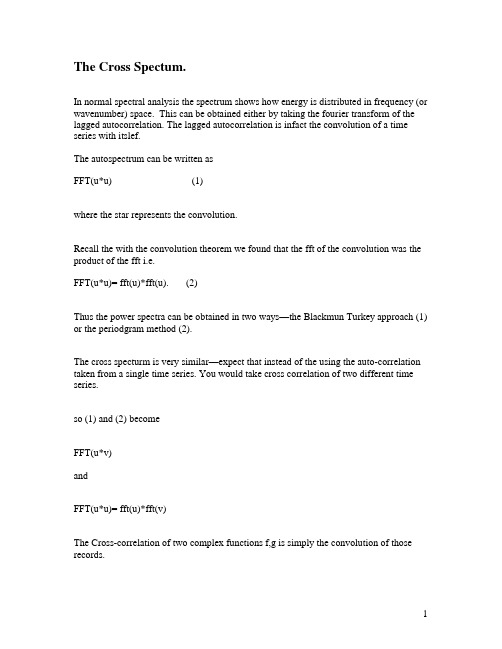
The Cross Spectum.In normal spectral analysis the spectrum shows how energy is distributed in frequency (or wavenumber) space. This can be obtained either by taking the fourier transform of the lagged autocorrelation. The lagged autocorrelation is infact the convolution of a time series with itslef.The autospectrum can be written asFFT(u*u) (1)where the star represents the convolution.Recall the with the convolution theorem we found that the fft of the convolution was the product of the fft i.e.FFT(u*u)= fft(u)*fft(u). (2)Thus the power spectra can be obtained in two ways—the Blackmun Turkey approach (1) or the periodgram method (2).The cross specturm is very similar—expect that instead of the using the auto-correlation taken from a single time series. You would take cross correlation of two different time series.so (1) and (2) becomeFFT(u*v)andFFT(u*u)= fft(u)*fft(v)The Cross-correlation of two complex functions f,g is simply the convolution of those records.This can be conceptually understood by recalling the convolution is simply the sum of the product of the two records —with one record shifting down the time axis.Recall then that the fourier Transfrom of g*h was G(f) H(f)Therefore one could calculate the cross-correlation by taking the inverse fft of product of the fft of G and H.Likewise the fft of the autocorrelation of x (x*x) is equal to |X(f)|2.Summary of standard spectral analysis approach1 Remove mean and trend.2) Could Pad with K zeros to increase spectral resolution (K<N). This partially reduces end effects ( second motivation to do this is to get the record to be a power of two —for faster fft —however this is typically not an issue if the data set is not to large). Padding with zeros also allows one to select a record length such at a fourier frequency will fall exactly on a major Harmonic (if one exists), it improves spectral resolution.3) Break up the data into equal blocks of size M4) Take FFT and average results in frequency space.5) Rescale spectra to account for the loss of energy for given window. For the Hannign window mulitpy by 8/sqrt(3).6) Compute the raw spectral density for the two-sided spectrum as22102)()(1)(1)(f Y t K N dte y t t K Nf S K N n n fn i n yy ∆+=∆∆+=∑-+==-πGyy(0)=Sff(0)Gyy(1,n-1)=2*Sff(1,n-2)Gyy(n)=Sff(n)One is the calculation of energy from the fft. We need to divide by T and multiply Each spectral constituent by 2 except the first and the last.Cross-Covariance Functiontm t n x t n x m N C m N ∆=+∆∆-=∑-τττ12112)()(1)(Cross-correlation Function2/122111212)]0()0([)()(C C C ττρ=x1 and x2 are different time series —could be apples and oranges!FOr example supplse X1 and X2 were sea-level observations at Sandy Hook and Atlantic City n The time lag of maximum correlation is the time that the signal travels down the coast the coast.They can be complex numbersFor example if you had two vector time series —say surface currents and wind, you would make these time series into complex numbersU=u+i*v CurrentW=ue+i*un windHere’s an example using MA TLAB to using complex numbers to get the correlation, between a scalar times series and a vector time series.Wind_eta_Correlation.m matlab scriptWind and Sea-level at the Battery.w=u+i*v;c1=corrcoef(h,w);R=real(c1(1,2));I=imag(c1(1,2));ang=atan2(I,R);% Rotate wind so that real part is along axis correlated with windw=w*exp(-i*ang);u=real(w);v=imag(w);corrcoef(h,u)After rotation you could find the lag that produces the maximum correlation between the wind and sealevel records.2/1111*1*1)()(1),,(⎪⎪⎭⎫ ⎝⎛⎥⎦⎤⎢⎣⎡⎥⎦⎤⎢⎣⎡+∆∆-=∑∑∑-N N mN W W N U U N t n W t n U mN W U ττρlag_corr.m matlab scriptNearly 80% of the variance in low-frequency sea-level is attributed to wind forcing.This could probably be improved if I removed barometer effectsHowever it will never be 100 % because other processes effect sea-level such as that are not correlated with winds such as:Waves (coastally trapped)Tides (long period —these could be removed)River discharge may impact sea-level at Battery.Still, 80% is pretty good.The first analysis —finding the wind direction that yields the best correlation could also be done with a lagged correlation. This might yield slightly differenceTo extend this into the frequency domain —to characterize the cross-correlation as a function of frequency we estimate the cross-spectraTime series may be better correlated in some frequencies than in others.Following Blackman the Tukey we could take the spectra of the cross-correlation function to yield the cross spectra —Or we could take FFT of each record obtain Y1(f), Y2(f) and the cross spectra is simply Cs=Y1* Y2Note that since this is not the autospectra that Cs will be complex. This is important because it give us phase information on the two series —Who leads Who!For example current velocity and temperature fluctuations can drive a net heat flux —if they are in phase. This is often referred to as an eddy heat flux. The cross-spectrum of temperature and velocity would give a frequency dependent measure of the eddy heat flux.)(')(''t T t u C q p ρ=Coherent fluctuations that are in phase produce heat flux. IF they are in quadriture (90 degrees out of phase) there is no heat flux in that frequency band.Show example of how advection due to oscillatory tidal motion will yield no- heat flux⎰=∂ωω0t t cos t sinBut⎰≠∂ωω0t t sin t sinCross SpectraTaking the cross spectrum is quite easy —identical to autospectra.1) Ensure that the time series span the same time/space period with identical2) resolution.3) Remove the means the trends from both records4) Determine how much block averaging you will need to do for statistical reliability.5) Window the data6) Compute FFT of data7) Adjust scale factor of spectra according to windowing8) Compute raw one-sided cross spectral density [])()(2)(21*12f X f X t N f G ∆=Since the cross-spectrum i s the transform pair of the covariance function the inverse Fourier transform of the cross-spectrum will recover the cross-covariance function . This is a more computationally efficient way to calculate the cross-covariance due to the robust computational efficiency of the fft.i.e.inv(G12)= cross-covarainesin matlabtwo time series x1 & x2.F=fft(x1)G=fft(x2);CC=ifft(conj(F) G)Two ways to quantify the real and imaginary parts of the cross-spectrum.1)product of an amplitude function (Cross amplitude spectrum) and a phasefunction ( phase spectrum)The amplitude spectrum gives the frequency dependent of co-amplitudes, while the phase indicates the relative phase between these two signals.When the co-amplitudes are large-that means that there are covariance in that frequency band—and the phase is meaningful. However if the amplitude is small (specifically statistically insignificant) then the phase is meaningless. (Need to discuss significance levels for this).So the amplitude is simply G*conj(G)And the phase isAtan2(imag(g), real(G))Easily done in Matlabx k(t)=A k cos(2πf o t+θκ) κ=1,2The Fourier transform of this is the sinc function that is shifted by e iθ(note that for zero phase shift e0 is 1)i.e. X k(f)=A k/2(e iθk sinc(f- f o)T+ e-iθκsinc(f+ f o)T) k= 1,2Hence the cross-power-spectra of these two time series would beS12(f)= 1/T (X1(f) X*2(f))[]T f f c e T f f c e T f f c e T f f c e T A A f S o i o i o i o i )(sin )(sin )(sin )(sin 4)(221122111++-+++-=--φφφφFor T going towards inifinity[])()(2)()()(2112o i o i f f e f f e T A A f S ++-=∆∆-δδφφMore generally the sample cross-spectrum (one-sided) would read[][])f (12i 2112)}f (2)f (1{i 2112e T A )f (S ore T A A )f (S φθ-φ==So A12 is frequency dependent amplitude of the cross spectrum and theta is thefrequency depended phase of the cross spectra. The phase only has meaning when the amplitude is significantly different than zero.Here we can Show MATLAB examples of cross-spectrum for1) Single frequency with phase2) Multiple Frequency3) Sea-level and Wind at the Battery.It can also be decomposed into a co-spectrum (in phase fluctuations) and quad-spectrum (fluctuations that occur in quadrature). This is also related to the Rotary spectra that can decompose the cross-spectra of a vector time series into clockwise and counterclockwise rotating components.Ellipse analysis, (tidal ellipse)U=Acosωt+BsinωtV=Ccosωt+DsinωtThis can be written in complex form as:R=u+ivR= Acosωt+Bsinωt+i (Ccosωt+Dsinωt)R=(A+iC) cosω+(B+iD) sinωt (1)Since we are dealing with vector that oscillates at a single frequency this can be represented in terms of a clockwise rotating vector and a counter clockwise rotating vector.i.e.R=R+e iωt+ R-e-iωtWhere R+ and R- are the radii of the clockwise and counter-clockwise rotating constituents.Recalle iωt=cosωt+isinωtsoR= R+( cosωt+isinωt) + R-( cosωt-isinωt)R=( R++ R-) cosωt +i( R+- R-) sinωt (2)Solving for R+ and R- by equating equations (1) and (2) we find:2)(2)(B C i D A R B C i D A R ++-=-++=-+The magnitude of these are then()2/1224)(⎥⎦⎤⎢⎣⎡-++=+B C D A R()2/1224)(⎥⎦⎤⎢⎣⎡++-=-B C D A RSince these are rotating at the same frequency but in opposite directions there will be times when they are additive (pointing in the same direction) and times when they are pointing in opposite direction and tend to cancel each other out.These two times define the Major Axis is ( R ++ R - ) and the minor axis (R +- R -) of an ellipse .While the orientation and phase of the ellipses:G1=atan2(B1,A2)G2=atan2(B2,A2)OREN= 0.5*(G1+G2);PHASE=0.5*(G2-G1);WhereA1=(A+D)B1=(C-B);A2=(A-D);B2=(C+B)Back to the heat flux example – if fluctuations occur in phase (large co-spectrum amplitude) then there will be a large eddy heat flux.In contrast if the co-spectrum is small but the quad-spectrum is large there will be little eddy heat flux at that frequency.This of course could be induced by the amplitude and phase spectrums —but often this is a convienent way to plot it.Here the cross Spectrum, which has a real and complex part)(sin )()()(cos )()()()()(121212121212121212f f A f Q f f A f C where f iQ f C f S θθ-==-=Coherence spectrum (Coherency or Squared Coherency))f (12i 2/1212121222211222122211212212e |)f (|)f (and1||0)f (S )f (S |)f (Q )f (C |)f ()f (S )f (S |)f (S |)f (θ-γ=γ<γ<+=γ=γThe squared coherence represents the fraction of variance in x1 ascribable to x2 through a linear relationship between x1 and x2.Phase estimates are generally unreliable when amplitudes fall below the 90-95% confidence intervals.Confidence Intervals)1EDOF /(1211-α-α-=γEDOF is the independent cross-spectral realizations in each frequency band. Thomson and Emery suggest that it is equal to the number of frequency bands that you average.For 95 % confidence level α =0.05For EDOF=2)1EDOF /(1211)f (-α-α-=γ95.0295=γRequiring remarkably high coherence!!However for EDOF =553.0295=γA limit that is more likely to be exceeded to be found in a noisy geophysical data set!。
特斯拉动态引力理论原文

converted into energy. The canonical momentum is defined as follows below:
may be written as follows:
..
.
..
.
..=
ememobobRMRMcGz2, (9
where the subscripts specify the emitter and observer gravitational
potentials respectively. Since the redshift of an object at cosmological distance
.
...
.
..
.
.
..
.
.
+..
.
...++.+..
.
..
.=
⊕
⊕⊕
RcGMhRzzHcLhtEs21 ]1ln[1ln .(8)
In this theory, the predicted redshifts are significantly different when
, (1a) 44mvp=
where the velocity in the fifth dimension is given by:
..αγ.
=4v, (1b)
and is a time derivative where gamma itself has units of mass density or
毕业论文参考文献分析解析
毕业论⽂参考⽂献分析解析[1]严国敏.现代斜拉桥[M].成都:西南交通⼤学出版社,1996:2-3.[2]李鑫.⼤跨度斜拉桥施⼯过程中⼏何⾮线性⾏为分析[D],硕⼠论⽂2013,成都西南交通⼤学.[3]葛耀君.⼤跨度悬索桥抗风[M]北京.⼈民交通出版社,2011:17-53.[4]项海帆.结构风⼯程研究的现状和展望[J].振动⼯程学报,1997,l0(3)259-263.[5]胡俊.⼤跨度悬索桥现场实测数据、风⾬激励响应及风振疲劳研究[D].⼤连理⼯⼤学博⼠论⽂,2012.6[6] JamieE.Padgett, AprilSpiller,Candase Aronold. Statistical analysis of coastal bridgevulnerability based on empirical evidence from Hurricane Katrina[J].Structure and Infrastructure Engineering. 2012 ,8(6):596-605.[7]项海帆.进⼊21世纪的桥梁风⼯程研究[J].同济⼤学学报.2002,30(5):529-532.[8]李国豪.桥梁结构稳定与振动[M].北京:中国铁道出版社,2002.400-441.[9] Boonyapinyo V, Yamada H, Miyata T. Wind-induced nonlinear lateral-torsional buckling of cable-stayed bridges [J]. Journal of Structural Engineering ,ASCE, 1994,120(2):486-506. [10] A.Hirai,I.Okauchi, M.Ito,T.Miyata. Studies on the critical wind velocity for suspensionbridge[C]/Proc. Int, Res. Seminar on wind effects on buildings and structures. University of Toronto Press. Ontario, Canada, 1967:81-103.[11]⽅明⼭.超⼤跨径缆索承重桥梁⾮线性空⽓静⼒稳定理论研究[D],上海:同济⼤学桥梁⼯程系, 1997.[12]程进,江见鲸,肖汝诚,项海帆.⼤跨度桥梁空⽓静⼒失稳机理研究[J].⼟⽊⼯程学报,2002,35(1)35-39.13陈政清桥梁风⼯程[M].北京.⼈名交通出版社,2005:43-58;139-141.14 H.W.Rieleman,D.Surry,K.C.Mehta, Full/mofrl-dvalr comparison of surface pressures on the Texas Tech experimental building[J],J. Wind Eng Ind. Aerodyn.,1996.61(1):1-23.15 D.Surry, Pressure measurements on the Texas Tech building: Wind tunnel measurements andcomparisons with full scale[J],J. Wind Eng Ind.Aerodyn.,1991.38(2-3):227-234.16 J.L.Walmsley, P.A.Taylor, Boundary-layer flow over topography: impacts of the Askerveinstudy, Boundary-Layer Meteorol.78(1996):291-320.17 Gunter Schewe, Allan Larsen. Reynolds number effects in the flow around a bluff bridge deckacross section. Journal of Wind Engineering and Industrial Aerodynamics.1998,74-76:829-838 18同济⼤学⼟⽊⼯程防灾国家重点实验室.“风的湍流特性观测与分析”苏通⼤桥桥位⽓象观测、风参数研究(四期报告)[R].上海:同济⼤学,2004.19 张玥西部⼭区⾕⼝处桥位风特性观测与风环境数值模拟研究[D].长安⼤学博⼠论⽂.2009.12.20 Gunter Schewe, Allan Larsen. Reynolds number effects in the flow around a bluff bridge deck across section. Journal of Wind Engineering and Industrial Aerodynamic.1998,74-76:829-838.21罗云.CFD⽅法在边界层风洞流场模拟中的应⽤研究[D].上海:同济⼤学硕⼠学位论⽂,2000.6[22]刘明,沿海地区特性实测分析与⼤跨度桥梁抖振响应研究[D].成都:西南交通⼤学博⼠论⽂,2013.6.23 Rathbun, J.C. Wind forces on a tall building. Transactions of ASCE, 1940, 105:1-41.24 A.G Davenport. The Relationship of Wind Structure to Wind Loading. Paper No.2 Proc Confon Wind Effects on Buildings and Structures:N.P.L.1963.25 A.G Davenport. The Spectrum of Horizontal Gustiness Near the Ground in High Winds.Quarterly of the Roya1 Met soclety.1987,194-211.26 Harstveit K. Full scale measurements of gust factors and turbulence intensity, and theirrelations in hilly terrain[J].Journal of Wind Engineering and Industrial Aerodynamics, 1996,61(2) : 195-205.[27] T. Amano, H. Fukushima, T. Ohkuma et al. The observation of typhoon winds in Okinawa byDoppler sodar [J]. Journal of Wind Engineering and Industrial Aerodynamics.1999, 83(1):11-20.28 Shiau B S, Chen Y B. In situ measurement of strong wind velocity spectra and windcharacteristics at Keelung coastal area of Taiwan [J]. Atmospheric Research,2001,57(3) : 171-185.29 Cao S, Tamura Y, Kikuchi N, et al. Wind characteristics of a strong typhoon[J].Journal of WindEngineering and Industrial Aerodynamics,2009,97(1) :11-21.30李宏海,欧进萍.基于实测数据的台风风场特性分析[C].第⼆届结构⼯程新进展国际论坛论⽂集.2008:299-307.31顾明,匡军,韦晓等.上海环球⾦融中⼼⼤楼顶部良态风风速实测[J].同济⼤学学报(⾃然科学版)2011,39(11):1592-1597.32王浩,邓稳平,焦常科等.苏通⼤桥凤凰台风现场实测分析[J].振动⼯程学报2011,24(1):36-4033喻梅,倪燕平,廖海黎等, 西堠门⼤桥桥位处风场特性实测分析[J].空⽓动⼒学报.2013,31(2):219-224.34李正农,吴卫祥,王志峰.北京郊外近地⾯风场特性实测研究.建筑结构学报2013.34(9):82-90 35黄鹏,戴银桃,王旭等.上海沿海地区近地风脉动风速谱及相⼲性研究[J].⼯程⼒学学报2014,31(4):126-133.36 J. Bietry, D. Delaunay, E. Coti. Comparison of full-scale measurement and computation ofwind effects on a cable-stayed bridge [J]. Journal of Wind Engineering and Industrial Aerodynamics. 1995(57):225-235.37 J. B. Fr and son. Simultaneous pressures and accelerations measured full-scale on the Great Belt East suspension bridge [J]. Journal of Wind Engineering and Industrial Aerodynamics. 2001 (89) :95-129.38 T. Miyata, H. Yamada, H. Katsuchi et al. Full-scale measurement of Akashi-Kaikyo Bridgeduring typhoon [J]. Journal of Wind Engineering and Industrial Aerodynamics. 2002 (90): 1517-1527.39 John. H.G Macdonald. Evaluation of buffeting predictions of a cable-stayed bridge fromfull-scale measurements [J]. Journal of Wind Engineering and Industrial Aerodynamics.2003(91):1465-1483.40 Y. L. Xu, L. D.Zhu. Buffeting response of long-span cable-supported bridges under skew winds.Part 2: case study [J]. Journal of Sound and Vibration.2005(281):675-697.[41]陈政清,柳成荫,倪⼀清等.洞庭湖⼤桥拉索风⾬振中的风场参数[J].铁道科学与⼯程学报.2004, 1 (1) :52-57..[42]王修勇,陈政清,倪⼀清等.环境激励下斜拉桥拉索的振动观测研究[J].振动与冲击.2006, 25(2) :138-144.43王浩,李爱群,谢以顺.台风"麦莎"作⽤下润扬悬索桥抖振响应实测研究[J].空⽓动⼒学报.2008, 26 (3) :706-712.44王浩,李爱群,黄瑞新等.润扬悬索桥桥址区韦帕台风特性现场实测研究[J].⼯程⼒学.2009,26 (4) :128-133.45 李杏平,李g群,王浩等.基于长期监测数据的苏通⼤桥桥址区风特性研究[J].振动与冲击.2010, 29 (10) :82-85.46 Selvam R P. Computation of flow around Texas Tech building using k- t and Kato-Launder k-e turbulence model. Journal of Wind Engineering and Industrial Aerodynamics, 1996, 18:856-860.47 Kim H.G, Patel V.C. Test of Turbulence Models For and Flow over Terrain With SeparationAnd Recirculation [J]. BoundaryLayer Meteorology, 2000, 94(l): 5-21(17).48 Senthooran S, Lee D D, Parameswaran S. A computational model to calculate the flow inducedpressure fluctuations on buildings. Journal of Wind Engineering and Industrial Aerodynamics, 2004, 92: 1131-1145.49 Nozu T, Tamura T, Okuda Y, Sanada S. LES of the flow and building wall pressures in thecenter of Tokyo. Journal of Wind Engineering and Industrial Aerodynamics, 2008, 96: 1762-1773.50 谭红霞,陈政清.CFD 在桥梁断⾯静⼒三分⼒系数计算中的应⽤[J].⼯程⼒学学报,2009,26(11):68-72.[51]顾明,黄强,黄鹏等.低层双坡房屋屋⾯平均风压影响因素的数值模拟研究[J].建筑结构学报,2009,30(5):205-211.52卢春玲,李秋胜, 黄⽣洪等. ⼤跨度屋盖风荷载的⼤涡模拟研究[J].湖南⼤学学报( ⾃然科学版),2010,37(10):7-12.53张玥、胡兆同、刘健新.西部⼭区斜拉桥风特性观测及数值仿真[J].长安⼤学学报(⾃然科学版),2011,31(5):44-49.54 陈成, 基于实际⼭地地形的建筑风荷载数值模拟研究[D].重庆⼤学硕⼠论⽂.2012,4.55⾼亮.内陆强风特性的现场实测与模拟[D].长安⼤学博⼠论⽂,2012.1256⽅平治,史军,王强,等.上海陆家嘴区域建筑群风环境数值模拟研究[J].建筑结构学报,2013,34(9):104-111.57左春阳,梁峰.复杂⾼耸结构表⾯风压分布数值风洞研究[J].特种结构,2013,30(2):21-25.58徐枫,陈⽂礼,肖仪清等.超⾼层建筑风致振动的现场实测与数值模拟[J].防灾减灾⼯程学报,2014,34(1):51-57.59 王福军.CFD软件原理与应⽤[M].北京: 清华⼤学出版社,2004:7-12.60 江帆.Fluent⾼级应⽤与实例分析.北京:清华⼤学出版社,2008:8-12.61李明⾼,李明ANSYS13.0流场分析技术及应⽤实例.北京:机械出版社2012:4-17.62 Xu F Y, Ying X Y, Zhang Z. Prediction of unsteady flow around a square cylinder using RANS[C]. Applied Mechanics and Materials, 2011, 52-54: 1165-1170.63 Menter F R. Two-equation eddy-viscosity turbulence models for engineering applications[J].AIAA J., 1994, 32(8): 1598-1605.[64] Davenport A.G. Buffeting of suspension bridge by storm winds. J. Struct. Div.,ASCE. 1962,88(6): 233-264.[65] D avenport A.G. The dependence of wind load upon meteorological parameters. Proc. Int. Res.Seminar on Wind Effects on Build and Struct. University of Toronto Press,Toronto, 1968: 19-82.[66]庞加斌.沿海和⼭区强风特性的观测分析与风洞模拟研究[D].上海:同济⼤学博⼠学位论⽂,2006.[67] 公路桥梁抗风设计规范(JTG/T D60-01-2004)[S].北京:中华⼈民共和国交通部发布,2004.[68] J.O. Paulo, A.Y ., Bassam. On the prediction of turbulent flows around a full-scale buildings.Journal of Wind Engineering and Industrial Aerodynamics, 2000, (86): 203-212.[69]顾明,黄鹏,群体⾼层建筑风荷载⼲扰的研究现状及展望[J],同济⼈学学报,2003.31(7): 762-766.[70] 戴天帅. 基于CFD 桥梁典型断⾯三分⼒系数差异分析[D].重庆:重庆交通⼤学硕⼠学位论⽂,2012.静⼒三分⼒静⼒三分⼒系数是表征桥梁结构静风荷载的⼀组⽆量纲参数。
光电专业英语单词

专英单词Chapter 1 Geometrical OpticsModels of light: Rays and Waves Reflection and RefractionTotal internal Reflection Thin lensesLocating Images by Ray Tracing Thin Lens EquationSpherical Mirrors lens Aberrationelectromagnetic spectrum 电磁波谱 parallel ray 平行光线reflection 反射 refraction 折射 incident beam 入射光束outgoing ray 出射光束 the angle of reflection 反射角specular reflection 镜面反射 diffuse reflection 漫反射optically denser medium 光密媒质 optically thinner medium 光疏媒质transparent medium 透明介质 prism 棱镜 index of refraction 折射率positive lens 正透镜 negative lens 负透镜 optical axis 光轴optical instument 光学仪器 focal point 焦点 curvature 曲率paraxial approximation 傍轴近似 achromatic lens 消色差透镜object distance 物距 image distance 像距 focal length 焦距the lateral of linear magnification 横向放大率 spherical mirror 球面镜curved mirror 曲面镜 concave mirror 凹面镜 convex mirror 凸面镜spherical aberration 球差 coma / coma aberration 彗差field curvature 场曲 distortion 畸变 chromatic aberration 色差focusing mirror 聚焦面镜 objective lens 物镜 aspherics 非球面镜Chapter 2 Wave OpticsHuygens’ Principle Reflection and Refraction of Light WavesInterference of Light Interference of Thin FilmsDiffraction by a Single Slit Multiple-Slit Diffraction and GratingsResolution and the Rayleigh Criterion DispersionSpectroscopes and Spectra Polarization Scatteringwave crest 波峰 wave trough 波谷 wave surface /wavefront 波阵面constructive interference 相长干涉 destructive interference 相消干涉diffraction grating 衍射光栅 spectrometer 分光计 polarization 偏振Rayleigh scattering 瑞利散射 optical activity 旋光性 aperture 孔径half wave loss 半波损失 fringes of equal inclination 等倾条纹fringes of equal thickness 等厚条纹 diffraction grating 衍射光栅multiple-beam interference 多光束干涉 resolution 分辨率wavefront splitting interference 分波前干涉 diffraction aperture 衍射孔径amplitude splitting interference 分振幅干 wave velocity 波速spectroscope 分光镜 longitudinal wave 纵波 transverse wave 横波Chapter 3 Optical InstrumentsThe eye The Magnifying GlassCameras and Projectors Compound MicroscopesTelescope Other lensesPupil 瞳孔 Cornea 角膜 Lens 晶状体 Retina 视网膜near point 近点 far point 远点 Astigmatism 散光Myopia nearsightedness 近视 hyperopia farsightedness 远视zoom lens 变焦透镜 varifocal lens 变焦距镜头 Magnifying glass 放大镜Chapter 4 Principles of LasersLaser Principle Types of LasersControl of The Laser Outputtransition 跃迁 spontaneous emission 自发辐射 excited state 激发态stimulated emission 受激辐射 ground state 基态LASER —Light Amplification by Stimulated Emission of Radiationresonant cavity 谐振腔 pumped light 泵浦光;抽运光population inversion 粒子数反转 population distribution 粒子数分布bandwidth 带宽 wavetrain 波列 gain 增益 etalon 标准具feedback 反馈 threshold 阈值 multimode 多模 ring resonator 环形谐振腔stable and unstable resonators 稳定腔和非稳腔 the confocal resonator 共焦腔Semiconductor Lasers 半导体激光器 Solid State Lasers 固体激光器Fiber laser 光纤激光器 Ion and Atomic Lasers 离子及原子激光器Excimer laser 准分子激光器 Electro-ionization Laser 电致电离激光器Plasma Laser 等离子体激光器Q-SwitchingModulation of the Laser OutputMode Locking for Ultrashort PulsesQ switch Q 开关;调Q birefringence 双折射 isolator 隔离器piezo-electric crystal 压电晶体 quarter wave plate ? 波片harmonic wave 谐波 Acousto-optic modulation 声光调制Magneto-optic modulation 磁光调制 electro-optic modulation 电光调制SPM Self-phase Modulation 自相位调制PCM Pulse Code Modulation 脉冲编码调制active mode locking 主动锁模 passive mode locking 被动锁模Laser Manufacturing Technology Laser RadarLasers in MedicineLaser Welding 激光焊接 Laser Heat Treatment 激光热处理Laser Cutting 激光切割 Laser Marking 激光打标Laser Drilling 激光打孔 arc welding 电弧焊Laser Heat-Conduction Welding 激光热传导焊接Laser Deep Penetration Welding 激光深熔焊接laser cladding technology 激光熔覆技术Laser Texturing Technology 激光毛化技术Chapter optical communicationcontinuous wave 连续波 transverse electric mode 横电模transverse magnetic mode 横磁模 core 纤芯 cladding 包层SBS stimulated Brillouin Scattering 受激布里渊散射SRS stimulated Raman scattering 受激拉曼散射Multimode Fiber 多模光纤 Single Mode Fiber 单模光纤SIOF Step-Index Optical Fiber 阶跃折射率分布光纤GIOF Graded-Index Optical Fiber 渐变折射率分布光纤GVD Group Velocity Dispersion 群速度色散PMD Polarisation Mode Dispersion 偏振模色散Waveguide dispersion 波导色散 Material dispersion 材料色散FDM frequency division multiplexing 频分复用TDM Time Division Multiplexing 时分复用WDM Wavelength Division Multiplexing 波分复用DWDM Dense Wavelength Division Multiplexing 密集波分复用LED light emitting diode 发光二极管LD laser diode 激光二极管APD Avalanche photo Diode 雪崩光电二极管OFA Optical Fiber Amplifier 光纤放大器SLA/SOA semiconductor laser/optical amplifier 半导体光放大器preamplifer 前置放大器 active component 有源器件 attenuator 衰减器Transmitter 发射机 low pass filter 低通滤波器 isolator 隔离器Optical Circulator 光环行器 Optical switch 光开关 Passive component 无源器件ADM Add Drop Multiplexer 分插复用器AWG arrayed-waveguide grating 阵列波导光栅Ethernet 以太网 Internet of Things 物联网AON Active Optical Network 有源光网络PON Passive Optical Network 无源光网络PDH Plesiochronous Digital Hierarchy 准同步数字体系SDH Synchronous Digital Hierarchy 同步数字传输体系Chapter Holographyreconstruction 再现 development 显影photosensitive medium 感光介质 Optical Date Storage 光数据存储。
Spectral Density of Sample Covariance Matrices of Colored Noise

ci,j =
(6)
where the rows of the matrices X and X are the transformed rows of the matrix x. Colored noise is a random signal with a non-flat power spectrum. We are interested in the question how the profile of the power spectrum influence the spectral density of the sample covariance matrix. In what follows we assume that the data matrix x has independent rows with identical power spectra and zero mean. Then the elements of the matrix X are also of mean zero - see the definition (6). Moreover the elements in the rows of the matrix x are independent. The transform X leads therefore also to a matrix with independent rows. Since the signal phase is random we get
Spectral Density of Sample Covariance Matrices of Colored Noise
布鲁克600mhz 核磁共振波谱
英文回答:Brooke 600 MHz MRI is a high—resolution MRI technology often used for chemicalposition analysis and structural representation. The technique uses magnetic field and radio frequency pulses to stimulate the atomic core in the sample and to detect its resonance frequency under different magnetic fields, thereby obtaining a map of the sample's MRI. The Brooke 600 MHz MRI equipment has a working frequency of 600 MHz and is capable of providing high sensitivity and resolution maps for the analysis of variouspounds. Through the MRI testing of samples, information on the chemicalposition of the samples can be obtained quickly, assisting scientists and chemical workers in the development and analysis of new materials.布鲁克600兆赫核磁共振技术是一种高分辨率的核磁共振技术,常用于化学成分分析和结构表征。
该技术利用磁场和射频脉冲来激发样品中的原子核,并检测其在不同磁场下的共振频率,从而得到样品的核磁共振谱图。
利用辐射噪声对舰船进行定位
∂Kn ∂ξn
χ4 = - 2ξ3n( σn2 +
β2n γn )
-
( ) χ4 éëêê2σn
1
χ2 +
2ξ2n
-
ξn β2n γn
-
ξn β
γn
2n
ùûúú
4ξ2n( σ2n + β2n γn ) 2
ξn 由频散方程 β1ncos β1nH - ibβ2nKnsin β1nH = 0
决定,b = ρ1 / ρ2 ,β1n = k21 - ξ2n ,β2n = k22 - ξ2n ,Kn =
第 42 卷第 7 期 2021 年 7 月
哈 尔 滨 工 程 大 学 学 报 Journal of Harbin Engineering University
Vol. 42 №. 7 Jul. 2021
利用辐射噪声对舰船进行定位
刘亚琴3 , 杨士莪1,2,3 , 张海刚1,2,3 , 郭俊媛1,2,3 , 刘岩3
Abstract:Aiming at the positioning problem of target ship in environments with an elastic seabed, in this study, passive positioning for target ships is researched using the ship radiated noise. Based on the principle of matched field processing, the frequency difference between the frequency corresponding to the peak of the ocean waveguide spectrum and the peak of the spectrum of the received signal is defined as a cost function. When the cost function takes a minimum value, the depth and range of the ship can be obtained. In the typical sound velocity profile environment, whether the radiated noise power spectrum is a pure continuous spectrum or a continuous spectrum superimposed line spectrum, the simulation results show that the positioning method proposed in this paper can effectively estimate the target distance. When the radiated noise power spectrum superimposes the line spectrum, the positioning accuracy of the method will be reduced. The decrease in the positioning accuracy of the method can be compensated by increasing the frequency range. Applying the proposed positioning method to the experimental data obtained in Zhoushan can effectively estimate the positioning of the target ship. Keywords:ship; radiated noise; continuous spectra; matched field processing; peak of spectrum; frequency difference; elastic half-space; passive location
[转载]SeismoSignal-地震波处理软件
![[转载]SeismoSignal-地震波处理软件](https://img.taocdn.com/s3/m/fb06c9e8fbb069dc5022aaea998fcc22bcd1432b.png)
[转载]SeismoSignal-地震波处理软件\(^o^)/~原⽂地址:SeismoSignal-地震波处理软件作者:concreteSeismoSignal-地震波处理软件,功能⾮常强⼤。
功能:基线调整和滤波、加速度积分、傅⽴叶谱和能量谱、响应谱等等。
FeaturesSeismoSignal constitutes an easy and efficient way to process strong-motion data, featuring a user-friendly visual interface and being capable of deriving a number of strong-motion parameters often required by engineer seismologists and earthquake engineers. SeismoSignal calculates:The elastic and constant-ductility inelastic response spectraThe Fourier and Power spectraThe Arias (Ia) and characteristic (Ic) intensitiesThe Cumulative Absolute Velocity (CAV) and Specific Energy Density (SED)The Root-mean-square (RMS) of acceleration, velocity and displacementThe Sustained maximum acceleration (SMA) and velocity (SMV)The Effective design acceleration (EDA) Acceleration (ASI) and velocity (VSI) spectrum intensityThe predominant (Tp) and mean (Tm) periodsThe Husid and energy flux plotsThe Bracketed, uniform, significant and effective durationsSeismoSignal also enables the filtering of unwanted frequency content of the given signal. Three different digital filter types are available, all of which capable of carrying out highpass, lowpass, bandpass and bandstop filtering.The program is able to read accelerograms defined in both single- and multiple-values per line formats (the two most popular formats used by strong-motion databases), and can apply baseline correction and filtering prior to time-integration of the signal (to obtain velocity and displacement time-histories).Finally, and due to its full integration with the Windows environment, SeismoSignal allows for numerical and graphical results to be copied to any Windows application (e.g. MS Excel, MS Word, etc.), noting that the characteristics plots can be fully customised from within the program itself.Screen-shots/P>SeismoSignal working environment Inelastic spectraElastic spectrum in theOriginal and filtered signalAcceleration-Displacement spaceFourier and Power Spectra Ground motion parameters Download/en/download_details.aspx?ID_Download=1。
UNB
3. Power spectrum analyses of VMSK
3.1. VMSK baseband waveform and expression
According to the character of VMSK coding, VMSK baseband signal can be decomposed into two waveforms shown in figure 1 (b) and (c). Figure 1 (b) has the same waveform which is called modulation clock in one bit time, while the modulation information is shown in figure 1 (c). Figure 1 (b) waveform and (c) waveform equals VMAK baseband waveform.
1-4244-0517-3/06/$20.00 ©2006 IEEE
1
3.1.1. Analysis of VMSK waveform. Given the transmission speed fb or the code interval Tb = 1/ fb , VMSK signal e(t ) may be seen as the summation of two signals which are incompatibility at time domain, namely e (t ) = e0 (t ) + e1 (t ) . The signal e0 (t ) is a periodic signal based on the basic waveform g0 (t ) which is shown in figure 2. So, The signal e0 (t ) with the period Tb can be expressed as
gc-ms
GC-MSIntroductionGC-MS (Gas Chromatography-Mass Spectrometry) is an analytical technique used to identify and quantify volatile and semi-volatile compounds in a sample. It combines the separation power of gas chromatography with the detection and identification capabilities of mass spectrometry. This powerful technique has a wide range of applications in various fields such as environmental analysis, food and beverage industry, pharmaceutical analysis, forensic science, and more.Principle of GC-MSThe principle of GC-MS involves two main steps: the separation of the sample mixture using gas chromatography and the detection and identification of the separated compounds using mass spectrometry.Gas Chromatography (GC)Gas chromatography is a widely used technique for separating and analyzing volatile compounds in a sample. It utilizes the principle of differential partitioning between a stationary phase (usually a fused silica column coated with a stationary phase) and a mobile phase (an inert gas such as helium or nitrogen). The sample is injected into the column and then carried by the flowing mobile phase through the column. The different compounds in the sample mixture have different affinities for the stationary phase and mobile phase,resulting in their separation based on their respective retention times.Mass Spectrometry (MS)Mass spectrometry is a technique used to determine the molecular structure and composition of compounds based on their mass-to-charge ratio (m/z). In GC-MS, the separated compounds from the gas chromatography step are introduced into the mass spectrometer for further analysis. The mass spectrometer consists of three main components: an ion source, a mass analyzer, and a detector. In the ion source, the separated compounds are vaporized and ionized, typically using electron ionization (EI). The ionized compounds are then accelerated into the mass analyzer, where they are separated based on their m/z ratios. The separated ions are finally detected, and the mass spectrum is generated, which provides information about the molecular weight and fragment ions of the compounds.Applications of GC-MSGC-MS has a wide range of applications in various fields due to its high sensitivity, selectivity, and capability to analyze complex mixtures. Some common applications of GC-MS include:Environmental AnalysisGC-MS is extensively used in environmental analysis for the detection and quantification of volatile organic compounds (VOCs) and semi-volatile organic compounds (SVOCs). It is employed in the analysis of air, water, soil, and otherenvironmental matrices. GC-MS helps in monitoring and assessing the presence of pollutants, identifying the source of contamination, and evaluating the effectiveness of remediation strategies.Food and Beverage IndustryGC-MS plays a crucial role in the food and beverage industry for quality control, authenticity testing, and safety assessment. It is used for the analysis of flavor compounds, additives, pesticides, mycotoxins, and other contaminants. GC-MS enables the identification and quantification of compounds that contribute to the aroma, taste, and overall quality of food and beverages. It also helps in detecting adulteration and verifying the label claims.Pharmaceutical AnalysisIn pharmaceutical analysis, GC-MS is used for the identification and quantification of drug substances, impurities, degradation products, and metabolites. It is applied in drug development, quality control, and forensic analysis of pharmaceuticals. GC-MS provides valuable information regarding the purity, stability, and composition of drugs, helping in ensuring their safety and efficacy.Forensic ScienceGC-MS is widely employed in forensic science for drug testing, forensic toxicology, arson investigation, and identification of volatile compounds related to crimes. It enables the detection and identification of drugs, metabolites, explosives, accelerants, and other trace substances in forensicsamples. GC-MS analysis plays a crucial role in supporting legal investigations and providing scientific evidence in the court of law.Advancements in GC-MS TechnologyGC-MS technology has witnessed significant advancements over the years, leading to improved performance, efficiency, and ease of use. Some notable advancements include:Triple Quadrupole GC-MS (GC-QQQ)Triple quadrupole GC-MS instruments provide enhanced sensitivity, selectivity, and dynamic range compared to traditional single quadrupole systems. They offer improved quantitation capabilities for trace analysis and complex samples. The triple quadrupole configuration enables the use of multiple reaction monitoring (MRM), enhancing the selectivity of the analysis.Time-of-Flight GC-MS (GC-TOF)Time-of-flight GC-MS instruments offer high-resolution mass spectra and accurate mass measurements. They provide comprehensive spectral data, allowing for retrospective analysis and identification of unknown compounds. GC-TOF instruments are particularly useful in metabolomics, profiling complex samples, and non-targeted analysis.Comprehensive Two-Dimensional GC-MS (GCxGC-MS)Comprehensive two-dimensional GC-MS combines two columns with different selectivities, resulting in enhanced separation power compared to traditional one-dimensional GC. It provides improved resolution and peak capacity, enabling the analysis of complex samples with overlapping peaks. GCxGC-MS is employed in various applications such as petroleum analysis, environmental analysis, and flavor profiling.ConclusionGC-MS is a powerful analytical technique that combines the separation capabilities of gas chromatography with the detection and identification capabilities of mass spectrometry. It has widespread applications in environmental analysis, food and beverage industry, pharmaceutical analysis, forensic science, and more. Advancements in GC-MS technology have further expanded its capabilities, allowing for enhanced sensitivity, selectivity, and efficiency. GC-MS continues to be an essential tool for scientists and analysts in various industries, enabling them to uncover valuable insights about complex samples and contribute to scientific advancements.。
- 1、下载文档前请自行甄别文档内容的完整性,平台不提供额外的编辑、内容补充、找答案等附加服务。
- 2、"仅部分预览"的文档,不可在线预览部分如存在完整性等问题,可反馈申请退款(可完整预览的文档不适用该条件!)。
- 3、如文档侵犯您的权益,请联系客服反馈,我们会尽快为您处理(人工客服工作时间:9:00-18:30)。
a r X i v :a s t r o -p h /0102191v 1 11 F eb 2001Accepted for publication in the Astrophysical Journal LettersPreprint typeset using L A T E X style emulateapj v.14/09/00VELOCITY AND DENSITY SPECTRA OF THE SMALL MAGELLANIC CLOUDS.Stanimirovi ´cArecibo Observatory,NAIC/Cornell University,HC 3Box 53995,Arecibo,Puerto Rico 00612sstanimi@zarianUniversity of Wisconsin,475North Charter Street,5534Sterling Hall,Madison,Wisconsin 53706Accepted for publication in the Astrophysical Journal LettersABSTRACTThis paper reports results on the statistical analysis of HI turbulence in the Small Magellanic Cloud (SMC).We use 21cm channel maps,obtained with the Australia Telescope Compact Array and the Parkes telescope,and analyze the spectrum of observed intensity fluctuations as a function of the velocity slice thickness.We confirm predictions by Lazarian &Pogosyan (2000)on the change of the power law index and establish the spectra of 3-D density and velocity.The obtained spectral indices,−3.3and −3.4,are slightly more shallow than the predictions for the Kolmogorov spectrum.This contrasts to the predictions for the shock-type spectra that are steeper than the Kolmogorov one.The nature of the energy injection in the SMC is unclear as no distinct energy injection scales are observed up to the entire scale of the SMC.Subject headings:ISM:general –ISM:kinematics and dynamics –ISM:structure –galaxies:individual(SMC)–turbulence1.introductionMany observations in the past decade have challenged the traditional picture of the interstellar medium (ISM).Instead of a two-level hierarchical system,consisting of clouds uniformly dispersed in the intercloud medium (the so called ‘standard cloud’model,Spitzer 1978),the ISM shows an astonishing inhomogeneity,with many levels of hierarchy.In order to consider real density functions in physical processes,a better understanding of the inventory and topology of the ISM is essential,as well as of the pro-cesses responsible for their creation.Having an extremely gas-rich ISM,dwarf irregular galaxies are particularly suit-able for such studies.Here we discuss the inventory of the ISM in the Small Magellanic Cloud (SMC),using the spa-tial power spectrum,and point to several processes that may be involved in the sculpturing of its ISM.The SMC is a nearby 1,extremely gas-rich,dwarf irreg-ular galaxy.Taking a part in an interacting system of galaxies (with other members being the Large Magellanic Cloud,LMC,and our Galaxy),the SMC’s morphology,dynamics and evolution is very complex.Being one of our closest neighbors,the SMC is attractive for various astro-physical aspects.The inventory of the cool ISM in the SMC was recently studied using the high resolution radio observations of neutral hydrogen (HI)(Stanimirovic et al.1999).Also,the dust properties of the SMC were investi-gated in detail,and the relationship between the cool gas and dust,using both HI and infrared (IR)observations (Stanimirovic et al.2000).As a dwarf,irregular galaxy,the SMC is different from our own Galaxy in many respects:its interstellar radiation field (ISRF)is more than four times stronger (Lequeux 1989),its heavy element abundance is almost ten times lower (Sauvage &Vigroux 1991),its dust grains are on average smaller by ≈30%(Rodrigues et al.1997)and sig-nificantly hotter (Stanimirovic et al.2000),and the cool atomic phase of HI is only half as abundant (Dickey et al.2000).In spite of all the above,the SMC appears to have similar interstellar turbulence properties,in having similar power law index as the Galaxy for the 2-D spatial power spectrum of its HI and dust column density distributions (Stanimirovic et al.2000).What do the 2-D spatial power spectra of the intensity fluctuations mean?Relating the fluctuations of intensity in PPV (position-position-velocity)data cubes and the un-derlying 3-D velocity and density statistics is a problem that has been recently addressed in Lazarian &Pogosyan (2000),where it was shown that changing the thickness of the velocity slice it is possible to recover both spectra of turbulent velocity and density.The SMC provides an ideal testing ground for this theory and we apply theo-retical predictions to the data.Elsewhere we plan to ap-ply alternative tools for turbulence studies,e.g.Principal Component Analysis (PCA)(Heyer &Shloerb 1997;Brunt &Heyer 2001),the ∆-variance (Stutzki et al.1998)and the spectral correlation function (Rosolowsky et al.1999)(see review by Lazarian 1999)to the SMC data.The structure of this paper is organized as follows.In Section 2we describe briefly the HI observations of the SMC.In Section 3we review previous results of the sta-tistical investigation of HI in the SMC,using the spatial power spectrum,and investigate the influence of velocity fluctuations on the intensity parison with earlier work and discussion on the origin of the turbulence in the SMC,are given in Section 4.2.hi dataThe small-scale HI structure in the SMC was observed with the Australia Telescope Compact Array (ATCA),a radio interferometer,in a mosaicing mode (Staveley-Smith 1We assume the SMC to be at the distance of 60kpc throughout this study.12S.Stanimirovi´c&zarian et al.1997).Observations of the same area were obtainedalso with the64-m Parkes telescope,in order to map thedistribution of large-scale features.Both sets of obser-vations were then combined(Stanimirovic et al.1999),resulting in thefinal HI data cube with the angular reso-lution of98arcsec,the velocity resolution of1.65km s−1,and the1-σbrightness-temperature sensitivity of1.3K,tothe continuous range of spatial scales between30pc and4kpc.The velocity range covered with these observationsis90to215km s−1.For details about the ATCA andParkes observations,data processing and data combina-tion(short-spacings correction)see Staveley-Smith et al.(1997)and Stanimirovic et al.(1999).3.statistical investigationThe2-D spatial power spectrum,P(k),of the HI emis-sionfluctuations(I)in the SMC wasfirst derived in Sta-nimirovic et al.(1999).This was thefirst such study foran entire galaxy.The power spectrum is defined as theFourier transform of the autocorrelation function of theHI emissionfluctuations:P(k)= I(x)I(x′) e−i L·k d L,L=x−x′(1)with k being the spatial frequency,measured in wave-lengths,and L being the distance between two points.To derive P(k)the channel maps(approximately5km s−1wide)were Fourier transformed.The averagevalue of the square of the modulus of the transform,ℜ2+ℑ2 ,was then measured in18annuli of equal width√in logVelocity and density spectra of the SMC3canfind the slope of velocityfluctuations to be m≈0.4, which means that the3-D velocity spectrum index is−3.4, which is very close to the3-D density spectral index.The transition point between density and velocity dominated regimes is equal to the velocity dispersion on the scale of the whole SMC(∼4kpc),which is∼22km s−1(Stan-imirovic et al.,in preparation).4.discussionAs the spatial power spectrum shows the importance of structure on various spatial scales,its power-law behav-ior suggests the hierarchical structure organization in the ISM,without preferred spatial scales.This phenomenon is usually ascribed to the interstellar turbulence(Scalo1987; Elmegreen2000).However,without velocity information one can always wonder whether we deal with a static struc-ture or a real turbulence.Indeed,a distribution of sizes of sand grains on a beach also follows a power-law,but no one would call this“turbulence”.The velocity information changes the picture dramatically.Hence,the extreme im-portance of the techniques which relate the observed2-D power spectrum with the underlying3-D statistics of both density and velocity.Here,we have tested the theoreti-cal predictions for such a technique(Lazarian&Pogosyan 2000),and as a result proved,for thefirst time,the pres-ence of an active turbulence in the SMC.In view of theoretical results in Lazarian&Pogosyan (2000)it is now appropriate to reanalyze all the earlier data.These data were obtained without much concern about the thickness of velocity slices.Therefore the ob-served variations of the power index can be due to transi-tions from“thin”to“thick”and to“very thick”slices.In the case of Green’s(1993)data additional complications are related to a divergent line of sight geometry.A more detailed discussion of the available data will be given else-where.We note that although the description in terms of power spectra is common in hydrodynamics and the MHD theory,it has certain limitations,as discussed in Lazarian (1999).For example,the power spectrum analysis does not include information about the phase distribution,dealing only with the modulus of the Fourier transform,nor it con-tains information about the structure connectivity(Scalo 1987).Other methods hence,should be used as comple-mentary statistical descriptors.Power spectrum as it is can provide us with an important insight of what kind of turbulence we deal with,e.g.distinguish the turbulence originating from shock waves from the hydrodynamic tur-bulence.The attempts to test Lazarian&Pogosyan(2000)theory were made recently in Elmegreen et al.(2000)using the HI observations of the LMC.In agreement with theoreti-cal predictions,the steepening of spectrum was observed for high spatial frequencies.The puzzling thing discovered by Elmegreen et al.(2000)was theflattening of the spec-tra for velocity-integrated intensity,which was interpreted as an effect of thefinite LMC disk thickness.This is an interesting explanation which entails that the LMC spec-trum at the scales larger than100pc becomes essentially two dimensional.Our study has not noticed a systematic change of the velocity integrated power spectrum at large spatial scales.This may reflect the fact that the SMC, unlike the LMC,is essentially a3-D entity.Another approach in relating the2-D with the3-D statistics in the case of the SMC was presented in Goldman (2000).There it is assumed that the densityfluctuations are a“passive scalar”,being driven by the velocityfluctu-ations,and hence having the same power spectrum.If we accept that the intensityfluctuations are due to the den-sityfluctuations,then the corresponding spectral index q of intensityfluctuations in a2-D slice can then be related to the3-D density spectrum index n asq=n+1,(2) which for the SMC data produces n≈−42.However,we note that the data used in Goldman(2000)are not in the real space(xyz)for which his treatment would be correct, but are in the velocity space(xyv).In this situation the Lazarian&Pogosyan(2000)treatment is appropriate and it provides a different result,namely,velocity index≈−3.4 and density index≈−3.3.Eq.(2)also predicts that the difference in the power slope between thin and thick slices is equal to1.This is inconsistent with Fig.1.We also note that for the Kolmogorov spectrum the predictions in Lazarian&Pogosyan(2000)(see Table1)coincide with n calculated using Eq.(2),but this correspondence is acci-dental.An interesting application of the power spectrum of HI opacityfluctuations was made by Deshpande(2000), in order to explain the long-standing puzzle of the tiny-scale structure in HI(Heiles1997).Assuming a single power spectrum of the opacityfluctuations,with a slope of2.75over the range of∼0.02pc to∼4pc,Deshpande (2000)obtained opacities consistent with the observations of small-scale HI structure in Deshpande et al.(2000). This is very encouraging and requires re-interpretation of previous observations of the small-scale structure in a sim-ilar way.A preliminary investigation of the small-scale structure found so far by Heiles(2000)suggested though a more complex structure function,with a significant change of slope for scales smaller than0.01pc.What can drive the turbulence in the SMC?The natural assumption would be that it is due to the stirring of the ISM produced by a large number of expanding shells found in the SMC.The shell sizes range from∼30pc to∼2kpc. Hence,one scenario could be that the largest shells drive the turbulent cascade down to smallest observed scales. However,processes like shell fragmentation and/or shell propagation from the smaller scales(bottom-up scheme, see Scalo1987),may play significant role too.The main problem in pinning down the exact mechanisms is that,so far,we have not observed changes in the power spectrum, at any scale up to the entire size of the SMC,which would be indicative of energy injection.An alternative explana-tion was suggested in Goldman(2000),whereby the large scale turbulence is induced by instabilities in the large-scaleflows during the last SMC–LMC encounter.Future comparison with simulations of different types of turbulent cascades are essential to resolve this question.5.conclusions2This would correspond to the spectrum of shock waves.To avoid possible confusion we point out that we talk about power spectrum which differs from the energy spectrum by k2.The Kolmogorov turbulence corresponds to the power spectrum of−11/3.4S.Stanimirovi´c&zarianWe have successfully tested predictions of the Lazarian &Pogosyan(2000)study on the change of slope of the in-tensityfluctuation spectrum with the velocity slice thick-ness.The SMC spectrum appears due to active turbulent motions rather than just a static hierarchical structure. We found the index for the3-D velocity spectrum to be −3.4,while for the density spectrum to be−3.3.REFERENCESBrunt,C.&Heyer,M.H.2001,ApJ,in press(astro-ph/0011200) Crovisier,J.&Dickey,J.M.1983,A&A,122,282Deshpande,A.A.2000,MNRAS,317,199Deshpande,A.A.,Dwarakanath,K.S.,&Goss,W.M.2000,ApJ, 543,227DDickey,J.M.,Mebold,U.,Stanimirovic,S.,&Staveley-Smith,L. 2000,ApJ,536,756Elmegreen,B.G.2000,ApJ,527,266Elmegreen,B.G.,Kim,S.,&Staveley-Smith,L.2000,ApJ,in press (astro-ph/0010578)Gautier,T.N.,Boulanger,F.,Perault,M.,&Puget,J.L.1992,AJ, 103,1313Goldman,I.2000,ApJ,541,701Green,D.A.1993,MNRAS,262,327Heiles,C.1997,ApJ,481,193Heiles,C.E.2000,in Radio interferometry:the saga and the science,ed.D.G.Finley&W.M.Goss,NRAO Workshop No.27 (Associated Universities),7Heyer,M.H.&Shloerb,F.P.1997,ApJ,457,173Lazarian,A.1999,in Plasma turbulence and energetic particles,ed. M.Ostrowski&R.Schlickeiser(Obserwatorium Astronomiczne, Uniwersytet Jagiellonski,Krak´o w),28Lazarian,A.&Pogosyan,D.2000,ApJ,537,720Lequeux,J.1989,in Recent Developments of MC Research,ed. K.S.de Boer,F.Spite,&G.Stasinska(Meudon,France: Observatoire de Paris),119Rodrigues,C.V.,S.J.,A.M.M.,Coyne,G.V.,&Piirola,V.1997, ApJ,485,618Rosolowsky,E.W.,Goodman,A.A.,Wilner,D.J.,&Williams, J.P.1999,ApJ,524,887Sauvage,M.&Vigroux,L.1991,in The Magellanic Clouds,ed. R.F.Haynes&ne,I.A.U.Symposium No.148(Kluwer, Dordrecht),407Scalo,J.M.1987,in Interstellar Processes,ed.D.J.Hollenbach& H.A.Thonson(D.Reidel Publishing Company),347 Schlegel,D.J.,Finkbeiner,D.P.,&Davis,M.1998,AJ,500,525 Spangler,S.R.1999,in Plasma turbulence and energetic particles, ed.M.Ostrowski&R.Schlickeiser(Cracow),1Spitzer,L.J.1978,Physical processes in the interstellar medium (New York,USA:J.Wiley&Sons,Inc),1Stanimirovic,S.,Staveley-Smith,L.,Dickey,J.M.,Sault,R.J.,& Snowden,S.L.1999,MNRAS,302,417Stanimirovic,S.,Staveley-Smith,L.,van der Hulst,J.M.,Bontekoe, T.R.,Kester,D.J.M.,&Jones,P.A.2000,MNRAS,315,791 Staveley-Smith,L.,Sault,R.J.,Hatzidimitriou,D.,Kesteven, M.J.,&McConnell,D.1997,MNRAS,289,225Stutzki,J.,Bensch,F.,Heithausen,A.,Ossenkopf,V.,&Zielinsky, M.1998,A&A,336,697Vazquez-Semadeni,E.,Pichardo,B.,Lazarian,A.,&Pogosyan,D. 2000,ApJ,submittedWaller,W.H.&Varosi,F.1997,in New Horizons from Multi-Wavelength Sky Surveys,ed.B.J.McLean,D.A.Golombek, J.J.E.Hayes,&H.E.Payne,I.A.U.Symposium No.179 (Kluwer,Dordrecht),194Table1A summary of analytical results for the2-D power spectrum of intensity fluctuations,P(k),derived inLazarian&Pogosyan(2000)for two distinct regimes of the3-D density fluctuations.The index of the3-Dpower spectrum of velocity fluctuations is−3−m.Slice Shallow3-D density Steep3-D densitythickness P s∝k n,n>−3P s∝k n,n<−3a channel width<velocity dispersion at the scale under studyb channel width>velocity dispersion at the scale under studyc substantial part of the velocity profile is integrated overVelocity and density spectra of the SMC5Fig.1.—The variation of the2-D HI power spectrum slope γ with the velocity slice thickness∆v.The dot-dashed lines distinguish thin, thick and very thick slice regimes.。