最新QDI_12使用说明书
济南展创12路高低温报警器说明书
济南展创12路高低温报警器说明书
1、接通智能温控器的电源,显示屏上显示的是当前的温度。
2、显示屏右下方是“启动温度”设置按钮,按升温键一下,温度提高1摄氏度;也可以按住不放手,温度连续升高。
例如设置为6 5摄氏度,也就是传感器温度低于或等于65度时,输出插座自动通电,所连接的设备启动。
3、显示屏左下方是“停止温度”设置按钮,例如设置为80度,即传感器温度高于或等于80度时,输出插座自动断电,受控设备停止工作。
4、再看温度传感器,它的作用是感知被监测对象的温度,并转变为电信号,通过导线传回温控器。
5、现在,把传感器吸附在被监测的设备上。
6、把受控设备的插头插在温控器输出插座上,注意的是最好在温控器本身未加电的状态下进行,至此,设置工作完成,温控器加电,该系统就开始工作了。
12轴步进电机控制说明书

27
2:ad
1:X 归零
28
2:Y 归零
3: Z 归零
四 速度 号 速度 电 速度 机 命 令 1:开启
0:关闭
脉冲高 脉冲低 31 脉冲高 脉冲低 32 脉冲高 脉冲低 33 脉冲高 脉冲低 34 脉冲高 脉冲低 35
36
反转 掉电 脉冲数赋值 前往坐标 加速启动
赋值为 0 等价于停止 单位为脉冲
据,则必须实时发送数据包回传请求:
表 4-2 限位开关含义
个位
左限位导通为 1 下限位导通 2 都不导通为 0
十位
左限位导通为 1 右限位导通为 2 都不导通为 0
百位
顶限位导通为 1 底限位导通为 2 都不导通为 0
注:如限位值为 210 含义为:Z 轴底限位导通+Y 轴左限位导通为 1+X 限位开关在常态。
虽然步进电机已被广泛地应用,但步进电机并不能象普通的直流电机,交流电机在常规下 使用。它必须由双环形脉冲信号、功率驱动电路等组成控制系统方可使用。因此用好步进电机 却非易事,它涉及到机械、电机、电子及计算机等许多专业知识。
ZJDR-01 运动控制卡是智俊电子潜心研制的一款价格便宜、使用方便的 USB 总线 12 轴运 动控制卡。外壳阳极氧化铝合金外壳,美观,散热好,自带十二轴 1A(峰值 2A)的步进电机 驱动器,驱动 42 电机游刃有余,能直接驱动部分 57 电机,每轴位置指令脉冲频率可达 300KHz, 支持十二轴联动,各自拥有自己的坐标系。启动与停止具有梯形速度控制功能,自带上位机。 并开源上位机源代码,适合二次开发,支持 PC 通过 USB 给控制器发出动作命令,也支持单片 机通过 5V 串口直连控制板,内置 15V 电平转换芯片,可远距离控制,外扩方面拥有 8 路继电 器,能直接控制汽缸,电磁阀,电机等,且能直接控制一个直流电机的正反转(需 4 个继电器配 合),4 路晶体管输出,其中 24 路输入内部上拉,可配置成限位开关(触发坐标变 0,电机即停), 或配置成状态输入(通过串口协议发送状态)。
海利普变频器说明书

·2·
海利普变频器
二、安装配线
1、储存 本产品在安装之前必须放置于包装箱内,若暂不使用,储存时请注意下列几
项: ● 必须置于无尘垢,干燥的位置; ● 储存环境温度-20℃到+65℃范围内; ● 储存环境相对湿度在0%到95%范围内,且无结露; ● 储存环境中不含腐蚀性气、液体; ● 最好放置在架子上,并适当包装存放。 ● 变频器最好不要长时间存放,长时间存放会导致电解电容的劣化,如需长 期存放,必须保证在1年内通电一次,通电时间至少5小时以上,输入时电 压必须用调压器缓缓升高至额定电压值。
海利普变频器
2、指示灯说明 1)指示灯状态说明
指示灯 FOR REV HZ
A ROTT A ROTT HZ ROTT HZ A ROTT
状态 亮 亮 亮 亮 亮 亮 亮 亮
说明 表示马达处于正转状态 表示马达处于反转状态 显示设定频率或输出频率 显示输出电流 显示马达转速 显示交流电压或直流电压 显示计数值 显示变频器内部温度
有效020002000200cd124过转矩检出方式选择过转矩检测准位过转矩检测时间020001200s10恒速中失速防止时减速时间故障重启动时间频率跟踪时电压上升时间501005马达额定电压马达额定电流马达极数马达额定转速按马达铭牌设定按马达铭牌设定0210009999cd134马达无载电流09940cd135马达转差补偿0010000cd136cd139保留输入输出端子cd120cd121cd122cd123cd125cd126cd127cd128cd129cd130cd131cd132cd133041440海利普变频器16参数功能一览表四分类功能码设定范围及功能说明出厂值cd140cd141cd142cd143cd144直流制动准位启动时直流制动时间停止时直流制动时间频率跟踪时间频率跟踪电流准位0020000250s00250s00200s0200cd145cd146cd147cd148cd149瞬停再起动选择允许停电时间异常再起动次数自动稳压功能自动省能源0
上海秋豪衡器 QDI-12D 称重显示器 用户说明书

Q D I -12D称重显示器用户操作手册QDI 系列称重显示器秋豪衡器 明察秋毫上海秋豪衡器有限公司Shanghai Queenhan Scales Co., Ltd.沪制00000312T:021-********M:137****3932第一章、概述QDI-12D称重控制仪适用定值控制和1-7种料配料控制,双显示、显示设定值和加料值、快速 A/D转换器及智能数字滤波器技术、抗干扰能力强,快速稳定、多种控制模式和多项控制参数设定,可广泛应用于配料系统。
由于采用了内部控制精度高于显示精度10倍的方式、使控制精度大大提高,而稳定性又很好,千分之一精度由万分之一技术保障,单料和多料加放料方式、自动修正方式可选择,加料、放料可选择是否受外部控制,以适用于种种不同场合。
可储存10个配方。
QDI-12-7采用嵌入式结构,铝合金外壳,抗干扰能力强。
操作简单,是各种配料秤的理想控制仪表。
备有RS-485接口、可多台仪表组合成集散控制系统。
第二章、主要功能和技术指标1)、双CPU结构,掉电数据保护。
2)、可储存10个配方。
3)、0.56"(字高14.2mm)双六位超高亮显示器。
4)、加料允许、放料允许、暂停、停止输入信号(触点或集电极开路)。
5)、13个触点输出信号(220V/3A)。
6)、电源(220V,50Hz)。
7)、工作温度 -10C - +40C,湿度<90%。
8)、A/D转换速度:100次/秒,分辨率100000。
9)、传感器供桥电压:+5V, 可驱动350欧传感器8个。
10)、零点温度漂移:<0.1uv/C。
11)、量程温度系数:<10 ppm/C。
12)、传感器灵敏度范围:0.5mv/v - 4.0mv/v。
13)、零位调整能力:100% F.S.。
第三章、外形尺寸及面板布置图第四章、接口§1、传感器接口,采用 D-SUB-9(孔)插座。
各引脚说明如下:1)、传感器正端反馈2)、传感器正电源3)、屏蔽地4)、传感器负电源5)、传感器负端反馈6)、空7)、传感器正输入8)、传感器负输入§2、串行接口,采用D-SUB-9(针)插头,各引脚说明如下:2.RXD3.TXD5. GND7. 485-A8. 485-B仪表必须有良好的接地。
Qleeno QS1012产品说明书

This is the safety alert symbol. It is used to alert you to potential personal injury hazards. Obey all safety messages that follow this symbol to avoid possible injury or death.SFA Companies, Inc.10939 N. Pomona Ave. Kansas City, MO 64153***********************************Protect your investment! Register your Qleeno at Model QS101! CAUTIONNOTICESIGNAL WORDSIndicates situation which, if not avoided, will result in death or serious injury Indicates situation which, if not avoided, Indicates situation which, if not avoided, could result in damage to propertyTABLE OF CONTENTSWarnings 2 Safety and General Information4 Product Description and Specifications 4 Preparation5 Operation7 Troubleshooting and Maintenance 8 Replacement Parts 11Warranty12Serial No. _______________________Date of Purchase ________________________SAFETY AND GENERAL INFORMATIONSave these instructions. For your safety, read, understand, and follow the information provided with and on this product before using. The owner and operator of this equipment shall have an understanding it's safe operating procedures before attempting to use. The owner and operator shall be aware that use and repair of this product may require special skills and knowledge. Instructions and safety information shall be conveyed in the operator's native language before use of this equipment is authorized. If any doubt exists as to the safe and proper use of this product, remove from service immediately.Inspect before each use. Do not use if broken, bent, cracked or damaged parts are noted. Any equipment that appears damaged in any way, or operates abnormally shall be removed from service immediately. It is recommended that an annual inspection be done by qualified personnel. Labels and Operator's Manuals are available from manufacturer.PRODUCT DESCRIPTIONQleeno is an electric powered, low-profile, wet floor scrubber. It scrubs and dries in one pass, and utilizes water and any common household floor cleaner. Qleeno is intended for commercial use only and is not a consumer product.SPECIFICATIONSWorking width15 in. (12" pad)Operating time, per tank10 - 30 min.Tank Volume0.8 gal.Voltage230/115V 50/60HzRated Power1500WSize (W x L x H)16-1/2" x 38-7/8" x 7-1/2"Weight (empty)66 lbs.Brush Pressure26.5 lbs.ControlConnectionWater/Cleaning Caster Adjust-PREPARATIONWARNING: Always turn Qleeno completely off and disconnect from power source when makingadjustments, changing brushes, performing any type of cleaning, maintenance, or repair work.CAUTION: Never use Qleeno without an extension cord, brush or pad holder with pad. Use only accesso-ries and equipment supplied or recommended by the manufacturer.Before Each Use1. Inspect Qleeno to make sure no damage has occurred during transport, storage or previous use.2. Inspect squeegee ring and change if edges or suction hoses show excessive wear.3. Inspect brush or scouring pad - replace if necessary.4. Ensure that correct brush/scouring pad is securely mounted to machine.5. Adjust casters to proper height (ref. page 6).6. Fill water tank with fresh water and chemical (if desired).NOTICE: Follow chemical manufacturer's instructions when using cleaning agent. Use only non-foaming clean-ing agents.NOTICE: Qleeno is not intended to be used as a buffer. Do not fill water tank with wax.NOTICE: After removing water tank, always carry with drain end down - water tank can spill if carried incorrectly.When replacing, set rear of tank on metal posts in frame side and insert tank ports in matching frame orifices.NOTICE: Always empty dirty water before each use.Place Water tank on metal posts at rearframe.Carry water tank drain end down - water can leak through ports in front.Mounting the brush/scouring pad1. With Kick Stand folded up, lift Qleeno to upright (vertical) position and turn brush/scouring pad holder counter-clockwise to remove it.2. Mount brush and turn clockwise until it contacts mounting tabs on hub (ref. photo below).3. If using scouring pad, fasten the pad to the velcro on the pad holder, then mount in same way as brush.NOTICE: For best results and longer pad life, ensure scouring pad is concentric with holder.Unfolding the HandleUnlock handle support locks on both sides of handle, raise handle to desired position and re-lock handle supports. Handle is adjustable to vertical position or intermediate positions to accomodate the user.Adjusting the CastersNOTICE: The Qleeno brush/pad should always operate as close to horizontal as possible, and should not cause the machine to drag or pull in any direction. Due to normal usage, the casters may require occassional adjustment.1. Pull knob on adjustment arm (ref. photo) and raise/lower the caster to desired position.2. Knob will lock into one of four detents in side of machine.OPERATIONStarting Qleeno1. Qleeno requires the use of an extension cord. Handle should be upright and locked.2. Mount brush or pad holder with scouring pad according to the instructions on previous page.3. Connect to common household current (110V) electrical outlet via extension cord.4. Tilt Qleeno backwards slighlty before starting to avoid damaging the scrubber. Start Qleeno by pressing Start/Stop Scrubber button on control pattern. The machine will perform a brief function test, after which the scrub -ber, water flow and suction will all commence.5. Regulate water flow with Decrease Water Flow or Increase Water Flow buttons on control panel. Adjust water suction with button shown below.1. Start/Stop Scrubber 3. Decrease Water Flow 6. Start/Stop Suction2. Scrubber Indicator Light4. Water Flow Indicator Lights 7. Suction Indicator Light5. Increase Water Flow8. Warning Light (red)Normal OperationBest results can be obtained by always using a full tank of clean water and chemical (if required). Move Qleeno in slow, overlapping lines over one portion of the surface at a time.NOTICE: Change direction slowly - do not move Qleeno in sudden or jerking motions.Judicious monitoring of water flow should provide the user with approximately 10 - 25 minutes of working time (low water flow setting - .03 gal/min; med water flow setting - .05 gal/min; high water flow setting - .10 gal/min).Turning off Qleeno1. Turn off water flow by pressing Decrease Water Flow button on control panel until all indicator lights go out. Continue cleaning for ten seconds to collect any excess water.2. Turn Qleeno off by pressing Start/Stop Suction button on control panel. Suction will continue for an additional two seconds.3. Disconnect power cord from power source.4. Empty dirty water tank.13568After Each Use1. Clean the hub insert and inside of the hub.2. Empty water tank. Position Qleeno over a floor drain and hold Decrease Water Flow button down for 3 sec-onds to empty clean water.3. Clean brush/pad and squeegee ring. Transporting QleenoCAUTION: Do not attempt lifting the entire machine without assistance. If transporting Qleeno a short dis-tance, simply tilt the machine back on the transport wheels.1. Unlock handle support locks, fold handle to lowest position and re-lock handle supports.2. Lift front of machine and roll Qleeno with weight supported on transport wheels.TROUBLESHOOTINGSymptomCorrective ActionQleeno will not start• Check electrical connection and fuse.Control panel Warning Indicator Light is on • Water tank is low. Empty dirty water and refill clean water.Qleeno makes beeping sound and shuts off • Water tank is empty. Empty dirty water and refill clean water.Water will not flow after starting • Check filters for clogging.Qleeno leaks water• Clean water tank seals.• Verify Water Fill cap is tight and properly threaded.• Check water pump on.• Inspect water tank for damage.Qleeno leaks water when lifted for transport• Check both caps on water tank firmly sealed.Qleeno drags or pulls in one direction while operating • Adjust casters (see pg. 5)MAINTENANCEWARNING: Do not remove the motor cover. Maintenance requiring removal of the cover should only beperformed by a qualified repair technician.Changing the FuseWait 15 minutes after shutting down before changing the fuse and attempting to restart the machine.The fuse is a standard 115V/10A, and is located under the control panel, near the electrical connection.Cleaning the HubWARNING: Always turn Qleeno completely off and disconnect it from the power source when not in use orbefore storing, making adjustments, changing brushes, performing any type of cleaning, maintenance, or repair work.NOTICE: The hub should be cleaned after each use to ensure optimum performance.1. Turn hub insert clockwise to release bayonet lock.2. Remove and clean hub insert. Clean inside of hub.3. To reassemble hub, mate grooves on hub insert with screws around hub, seat insert fully and turn counterclock-wise to lock in place.Changing the Squeegee Ring 1. Remove brush or pad holder.2. Disconnect all three suction hoses from hub.3. Lift squeegee ring just enough to allow access to nuts on mounting frame.5. Using an 8mm wrench, remove nuts holding squeegee ring to mounting frame and replace with new ring.6. To secure squeegee ring, follow steps 1 - 5 in reverse order.1. Hub 3. Squeegee Ring Mounting Frame 5. 8mm Nut2. Squeegee Ring4. Suction Hose315Adjustment of Suction HosesNOTICE: Proper adjustment of the suction hoses is essential to good operation. Check hose adjustment on aregular basis.1. Pinch hose to allow insertion into squeegee ring.2. End of suction hose should be approximately 1-3/16" from squeegee ring surface.Weekly Maintenance1. Make sure brush rotates freely.2. Inspect water tank for leaks and that membrane separating clean and dirty water is in good condition.Monthly Maintenance1. Perform Weekly Maintenance.2. Rinse water hoses by cleaning a section of a floor with a large amount of clean water.3. Thoroughly clean gaskets around water tank.4. Clean both fill and drain caps on water tank.5. Clean inside of both clean water and dirty water tank.After First 100 Hours of UseFrequency of use and type of environment will dictate when some maintenence is performed. Lubricate casters with silicone grease or spray. Inspect entire machine for damage, loose screws, nuts and other parts. Yearly MaintenanceIt is recommended that you take your Qleeno to the nearest authorized service center for thorough inspection.Before long periods of inactivity 1. Perform Monthly Maintenance.2. Empty machine of all water.3. Lubricate gaskets with silicone grease.After long periods of inactivity1. Inspect gaskets and wipe away excess silicone grease.2. Perform monthly maintenance.Approximate Critical Component Expected LifetimeSqueegee 600 hrs.Vacuum Tube 600 hrs.Brush 1000 hrs.AC Motor1000 hrs.DC Motor (brush replacement)2500 hrs.Timing Belt 1500 hrs.Water Pump 1500 hrs.Water Tank 2000 hrs.Casters2000 hrs.Transport Wheels2000 hrs.Item Part No.DescriptionQty 1710-3-9920-107Hood Assembly Repair Kit12710-4-8700-104Water Tank Assy (includes parts 3, 4)13710-3-9922-101Tank Fill (Large) Cap Repair Kit 14710-3-9921-109Tank Drain (Small) Cap Repair Kit 15710-6-8706-108Water Tank Gasket16710-3-9903-107Fuse Repair Kit (includes 10 fuses)17710-6-8105-102Water Distributor 18710-3-9916-106Vacuum Tube Repair Kit 39710-4-8500-106Squeegee Ring Assembly 110710-4-8501-108Brush111710-3-9902-105Caster Repair Kit112710-3-9901-103Transport Wheel Repair Kit113710-6-8911-109Extension Cord, 14 AWG (not shown)114710-3-9925-107Safety Labels 315qleeno rev 082011Owner's Manual1For information about Qleeno accessories, go to 98713246115121013REPLACEMENT PARTS11TWO YEAR LIMITED WARRANTYQleeno®, represented in the United States by SFA COMPANIES ("SFA") warrants to the original purchaser that this product is free from defects in material and workmanship for a period of two (2) years from date of purchase. The warranty is non-transferable and is subject to the terms, exclusions, and limitations described below:• Any damage resulting from misuse of neglect including, but not limited to bent squeegee rings, dented or crushed machine hoods, broken welds or punctured rubber bladders as well as worn out seals, o-rings and springs are the result of misuse and not covered by warranty and no warranty credit will be provided for such damaged components.• This warranty does not apply to ordinary wear and tear, overloading, alterations (including repairs or attempted repairs not performed by SFA or one of its authorized service centers).• This warranty is voided by improper fluid use, or use of the product in any manner for which the product was not intended use of the product in accordance with the instructions or warnings provided with the product and any modifications of the product.• In the unlikely event that a Qleeno product fails due to material defect in workmanship, you may contact SFA for disposition. Please contact our customer service department at (816) 891-6390 before proceeding with shipment or repairs on the product. In such cases, the customer’s sole and exclusive remedy for any breach or alleged breach of warranty is limited to the repair or replacement of the defective product.• Under no circumstances is SFA liable for any consequential such as lost profits or any other incidental damage whatsoever.• THIS WARRANTY IS LIMITED TO NEW PRODUCTS SOLD THROUGH AUTHORIZED DISTRIBUTORS AND OTHER CHANNELS DESIGNATED BY SFA. NO AGENT, EMPLOYEE OR OTHER REPRESENTATIVE OF SFA, IS AUTHORIZED TO MODIFY THIS WARRANTY.• THE FOREGOING IS EXCLUSIVE AND IS IN LIEU OF ALL OTHER EXPRESS AND IMPLIED WARRANTIES, INCLUDING BUT NOT LIMITED TO THE IMPLIED WARRANTIES OF MERCHANTABILITY AND FOR A FITNESS FOR A PARTICULAR PURPOSE. ALL OTHER WARRANTIES ARE EXPRESSLY DISCLAIMED. WARRANTY LAWS IN DIFFERENT LOCALITIES MAY VERY AND YOU MAY HAVE RIGHTS BY VIRTUE OF STATE OR LOCAL LAW.• SFA’s, liability in all cases is limited to, and will not exceed the purchase price paid for the product.• “Wear Items” such as accessories, motor carbon brushes, AC motor, squeegees, brushes, pads, vacuum tubes, wheels, casters, belts, bearings, and etc. are excluded unless found defective by Qleeno or SFA or an authorized service center.Some states do not allow limitations on how long an implied warranty lasts, so the above limitation may not apply to you. Some states do not allow the exclusion or limitation of incidental or consequential damages, so the above limitation or exclusion may not apply to you. This warranty gives you specific legal rights, and you may also have other rights, which vary from state to state.SFA Companies, Inc.10939 N. Pomona Ave., Kansas City, MO 64153816.891.6390***********************************。
DINI12水准仪使用说明
DINI12水准仪使用说明
一、性能特点
1、DINI12水准仪由高精度仪表和调节装置组成,具有精度高、快速定位、容错位置可调等特点。
2、测量范围高,最小精度可达0.01mm,可满足工程精度的要求。
3、可有效排除环境温度变化对测量结果的影响,保证测量结果的准确性和稳定性。
4、仪表上采用数字显示器,可以显示实时测量值,方便操作。
二、操作流程
1、安装。
将仪器放置在一平整的工作台上,确保稳定性。
2、连接。
将电源线正确接入,仪器上按钮就可点亮仪表。
3、调零。
打开仪表电源开关,将仪表上的“零”按钮按下,指示指针指向零位。
4、测量水平精度。
将激光笔准直放置在要测量的物体上,按下测量按钮,指示指针会指向要测量的水平精度值,将测量值读出即可。
三、注意事项
1、在使用DINI12水准仪之前,应检查仪器是否存在破损或明显变形的现象,如果是,则需要更换。
2、操作时,应按照操作说明,正确地使用仪器,以免造成损坏。
青岛布莱迪液位报警控制器说明书
青岛布莱迪液位报警控制器说明书摘要:一、液位报警控制器概述1.产品背景2.产品用途3.产品特点二、液位报警控制器安装与接线1.安装环境2.安装步骤3.接线方法三、液位报警控制器使用与操作1.操作面板2.功能键介绍3.使用方法四、液位报警控制器维护与故障排除1.维护保养2.常见故障3.故障排除方法五、液位报警控制器技术参数1.性能参数2.电气参数3.环境参数正文:【液位报警控制器概述】青岛布莱迪液位报警控制器是一款高精度的液位检测与控制设备,广泛应用于各类储罐、容器和反应釜等设备中,实现液位的实时监测、报警及控制功能。
该产品具有测量准确、稳定性好、抗干扰能力强等特点,可有效保障生产过程的安全与稳定。
【液位报警控制器安装与接线】1.安装环境:液位报警控制器应安装在干燥、无腐蚀性气体、无强烈振动和电磁干扰的环境中,避免阳光直射和雨淋。
2.安装步骤:首先确定安装位置,将液位报警控制器平稳放置在合适的位置上;然后按照接线图进行接线。
3.接线方法:液位报警控制器有红、黄、蓝、黑四根接线柱,分别对应火线、零线、控制线和信号输出线。
接线时,请确保接线牢固可靠,线号清晰无误。
【液位报警控制器使用与操作】1.操作面板:液位报警控制器面板上有各种功能键,包括设定键、复位键、上/下键等。
2.功能键介绍:设定键用于进入设定模式,进行参数设置;复位键用于恢复出厂设置;上/下键用于调整参数值。
3.使用方法:在使用过程中,请遵循操作规程,先开启电源,再进行设定和操作。
设定参数时,请根据实际需求进行设置,并确保参数值在合理范围内。
【液位报警控制器维护与故障排除】1.维护保养:定期检查液位报警控制器的运行状况,发现异常及时处理;保持设备清洁,避免灰尘和污垢影响性能。
2.常见故障:如设备无法正常启动、报警不准确、输出信号异常等。
3.故障排除方法:针对不同故障现象,可参考产品说明书进行排查;如无法解决,请联系售后服务人员寻求技术支持。
12导心电使用说明书V7.0
目录第一章前言............................................... 错误!未定义书签。
第二章概述. (4)2.1 使用环境 (4)2.2 安全方面的注意事项 (5)2.3 运行环境 (7)2.3.1 硬件组成 (7)2.3.2 软件环境 (7)第三章导联方式 (8)3.1 威尔逊(Wilson)标准导联 (8)3.2 富兰克(Frank)导联 (9)3.3 正交导联 (10)第四章软件功能 (11)4.1 软件登录界面 (11)4.2 系统主界面 (11)4.2.1 功能按钮 (12)4.2.2 病历列表 (15)4.2.3 病历查询 (16)4.3 新建病历 (16)4.3.1 新建常规病历 (16)4.3.2 新建预约病历 (17)4.4 采集12导病历 (17)4.4.1 波形采集 (17)4.4.2灵敏度设置 (19)4.4.3走纸速度设置 (20)4.5 采集15导病历 (20)4.5.1 波形采集 (20)4.5.2灵敏度设置 (22)4.5.3走纸速度设置 (23)4.6 采集16导病历 (23)4.6.1 波形采集 (23)4.6.2灵敏度设置 (25)4.6.3走纸速度设置 (26)4.7 采集18导病历 (26)4.7.1 波形采集 (26)4.7.2灵敏度设置 (28)4.7.3走纸速度设置 (29)4.8 12导回放分析 (29)4.8.1 12导回放分析界面 (29)4.8.2 功能按钮介绍 (30)4.8.3 心电显示方式 (33)4.8.4 波形设置功能介绍 (35)4.8.5 波形不同电压显示(半电压、双倍电压调整) (36)4.8.6 选择分析区域 (36)4.8.7 心拍放大与微调 (36)4.8.8 诊断 (37)4.9 15导回放分析 (38)4.9.1 15导回放分析界面 (38)4.9.2 功能按钮介绍 (39)4.9.3 心电显示方式 (42)4.9.4 波形设置功能介绍 (44)4.9.5 选择分析区域 (44)4.9.6 心拍放大与微调 (45)4.9.7 诊断 (45)4.10 16导回放分析 (46)4.10.1 16导回放分析界面 (46)4.10.2 功能按钮介绍 (47)4.10.3 心电显示方式 (50)4.10.4 波形设置功能介绍 (52)4.10.5 选择分析区域 (52)4.10.6 心拍放大与微调 (52)4.10.7 诊断 (53)4.11 18导回放分析 (54)4.11.1 18导回放分析界面 (54)4.11.2 功能按钮介绍 (55)4.11.3 心电显示方式 (58)4.11.4 波形设置功能介绍 (58)4.11.5 选择分析区域 (58)4.11.6 心拍放大与微调 (59)4.11.7 诊断 (59)4.12 打印 (60)4.12.1 快速打印 (60)4.12.2 常规打印 (62)4.13 快速心电 (62)4.14 新建检查 (62)4.15 编辑病历 (63)4.16 合并病历 (63)4.17 接收病历 (64)4.17.1 接收远程病历 (64)4.17.2 接收本地病历 (65)4.17.3 接收情况 (65)4.18 传输病历 (66)4.18.1 远程传输 (66)4.18.2 发送情况 (66)4.19 心向量回放分析 (67)4.20 频谱心电回放分析 (68)4.21 高频心电回放分析 (70)4.22 心率变异回放分析 (71)4.23 权限与审核 (72)4.24 系统设置 (72)4.24.1 基本设置 (72)4.24.2 分析设置 (73)4.24.3 打印设置 (73)4.24.4 数据库设置 (75)4.24.5 管理员设置 (75)4.24.6 工程师设置 (76)4.24.7数据维护 (77)第五章常见问题及解答 (78)第二章概述2.1 使用环境1.产品名称:十二导同步心电分析系统2.产品型号:MECG-200型3.产品分类:a)按电击防护分类,本产品属于Ⅱ类BF型设备;b)按有害进液防护分类,本产品属于不防进液的密封设备;c)按工作制分类,本产品属于连续运行的设备。
日光查看12英寸雷达说明书

Cost-effective, High-performance Radar with Powerful Standard Features DAYLIGHT-VIEWING 12-INCH RADARModels FR-7062/7112/7252True or relative echo trails,2 VRMs and 2 floating-origin EBLs,Target zoom and Off-centering.High-power (FR-7252: 25 kW) and high-speed antenna (48 rpm) available.FR-7062: 6 kWFR-7112:12 kWFR-7252:25 kWEspecially suited for medium- to small-sized vessels including professional fishing boats, workboats and pleasure craft, the FR-7062/7112/7252 are 12-inch X-band radars ingeniously designed based on FURUNO's years of experience and field-proven technical excellence in marine electronics.A high-speed 4 ft antenna unit (48 rpm) is optionally available to provide uninterrupted picture updating for high-speed vessels.These new radars incorporate advanced video processing technology and a logarithmic amplifier combined with automatic tuning and anti-clutter control to provide optimum picture quality on a high-definition CRT screen. Neatly arranged front panel controls include user-programmable function keys and a trackball associated with easy-to-understand menu for simple, user-oriented operation. Attractive standard features include two each VRMs and floating-origin EBLs, EBL/VRM offset, off-centering to cursor position, zoom, echo trails, echo stretch, trackball cursor with range/bearing readout, guard zone alarm, and quick restart of transmission in case of accidental power-off.Four presentation modes are available: Head-up, Course-up, North-up and True Motion with heading and speed data inputs. In True Motion mode, true echo trails can be displayed for easy recognition of moving and fixed targets.The guard zone alarm function allows you to set a fan- or ring-shaped guard zone at a desired position. There is a choice of inward and outward guard zone alarms. Visual and audible warnings are produced to warn of a target entering or exiting the guard zone. The Auto Plotter ARP-10 is optionally available for upgrading the FR-7062/7112/7252 to provideautomatic target plotting feature.water temperature and depth in graphics or alphanumerics if the radar is hooked up with appropriate sensors.targets on a collision course with your ship. Echo trails are displayed in monotone or multilevel shading with a trail length selected between 15 seconds and 30 minutes, or continuously.s 12-inch high-resolution CRT (effectivedia. 180 mm)s Highly visible 8-level target videogradations Head-Up, Course-Up*, North-Up* andTrue Motion** modess Logarithmic amplifiers Cursor position readout in L/L andrange/bearing***s Cursor position output in NMEA0183***s Two user programmable functionkeyss Automatic tuning and anti-cluttercontrols 48 rpm antenna for high-speedvessels (optional for 4 ft radiator only)s Auto Plotter ARP-10 for automaticplotting of 10 targets with vectors,warning against threatening targets,target data display incl. CPA/TCPA (optional)*Heading data required.**Heading and speed data required.***Heading and nav data required.ANTENNA RADIATOR1.Type Slotted waveguide array open radiator2.Length4 ft (XN12A) or 6 ft (XN13A)3.Rotation Speed 24 rpm standard(48 rpm optional for 4 ft radiator only)4.Wind Load 100 knots relative wind(70 knots for 48 rpm version)5.BeamwidthHor. 1.9°, Vert. 22°(4 ft radiator)Hor. 1.2°, Vert. 22°(6 ft radiator)RF TRANSCEIVER1.Frequency 9410 ±30 MHz (X-band)2.Output powerFR-7062: 6 kW FR-7112:12 kW FR-7252:25 kW3.Pulselengths and Pulse Repetition Rates (PRR)1/8 to 1.5 nm:0.08 µs/2100 Hz 1.5, 2 and 3 nm:0.3 µs/1200 Hz 3 to 96 nm*:0.8 µs/600 Hz (36 nm)550 Hz (48, 64 nm)500 Hz (72, 96 nm)*Max. range 64 nm for FR-7062, 72 nm for FR-7112 and 96 nm for FR-7252.4.Mixer and Local OscillatorMicrowave integrated circuit5.IF amplifier Logarithmic amplifier, IF 60 MHz Bandwidth:25 MHz (0.08/0.3 µs), 3 MHz (0.8 µs)6.Noise Figure 6 dB nominalDISPLAY1.Display Type12-inch, green phosphor CRT (8-level gradation)Effective diameter:180 mm Pixels: 481 (H) x 640 (V) dots2.Display Modes Head-up, Course-up*, North-up*,True motion***Heading data required.**Heading and speed data required.3.Range Scales and Range Ring Intervals (nm)Range:1/8,1/4,1/2,3/4,1,1.5,2,3,4,6,8,12,16,24,36,48,64,72,96Rings:1/16,1/8,1/8,1/4,1/4,1/2,1/2,1,1,2,2,3,4,6,12,12,16,18,24Max. range scale 64 nm for FR-7062, 72 nm for FR-7112,and 96 nm for FR-7252.4.Minimum Range 25 meters on 0.25 nm range5.Range Discrimination 20 meters or better6.Accuracy Range:1% of range in use or 15 m, whichever is greater Bearing:EBL accuracy ±1°or better7.Echo TrailsTrue or relative trails in single tone or multi-level shading Trail length:15, 30 sec., 1, 3, 6, 15, 30 min., or continuous8.Nav Data Input/OutputInputs (NMEA 0183 Ver. 1.5 or 2.0 format)--: Any talker $--APB, $--BWC,$--DPT,$--GLL*,$--GLC,$--HDG,$--MDA, $--RMA,$--RMB,$--RMC,$--VTG,$--XTE,$--DBK,$--DBS,$--DBT,$--GTD,$--HDM,$--HDT,$--MTW,$--BWR,$--VHW *NMEA 0183 Ver. 1.5 only.AD-10 format: Heading data Outputs (NMEA 0183 format)$RATLL, $RARSD, $RATTM w/ARP-109.Other FeaturesAutomatic tuning and anti-clutter control, Echo stretch, Two VRMs,Two floating-origin EBLs with true/rel bearing readout*, Cross cursor with range and true/rel bearing* plus L/L** readouts, Parallel index lines, Off-centering, Zoom, Quick restart in case of accidental power-off, Nav data display**, Visual and audible guard zone alarms, Two user-programmable function keys *Heading data required for true bearing readout.**Nav data inputs requiredENVIRONMENTAL CONDITIONS (Meets IEC 60945)Temperature:-25°C to +70°C (Antenna unit)-15°C to +55°C (Display unit)POWER SUPPLYFR-7062/7112:10.8 to 41.6 VDCFR-7252:21.6 to 41.6 VDC 115/230 VAC, 50-60 Hz, 1ø with optional rectifierEQUIPMENT LIST Standard1.Display Unit1 unit 2.Antenna Unit w/4 ft (24 or 48 rpm)or 6 ft (24 rpm) radiator1 unit 3.Antenna Cable 10, 15, 20 or 30 m1 pc.(Specify antenna type and cable length when ordering.)4.Power Cable 5 m1 pc.5.Standard spare parts and installation materials1 setOptions1.Rectifier RU-3423* for 115/230 VAC (*RU-174613-2 forFR-7252 with 4 ft/48 rpm and 6 ft/24 rpm antenna)2.Nav Cable MJ-A6SPF-0012-050 (5m)/-100 (10m) with 2x6 pinconnectorspass Cable MJ-A6SPF0007-100 (10 m) with 2x6 pin connectors4.External Alarm Buzzer OP03-215.Auto Plotter ARP-10 (to be built in display unit)6.Heading Sensor PG-1000 (w/10 m cable for AD-10 format)7.Gyro Converter AD-1008.Remote Display FMD-811 (LCD)9.Remote Display FMD-8010 (CRT)10.EMI Filter FP03-0550011.Color Filter FP03-0292012.Viewing Hood with Magnifying Lens OP03-12000055N Printed in JapanFURUNO U.S.A., INC.Camas, Washington, U.S.A.Phone: +1 360-834-9300 Telefax: +1 360-834-9400FURUNO (UK) LIMITEDDenmead, Hampshire, U.K.Phone: +44 2392-230303 Telefax: +44 2392-230101FURUNO FRANCE S.A.Bordeaux-Mérignac, FrancePhone: +33 5 56 13 48 00 Telefax: +33 5 56 13 48 01FURUNO ESPAÑA S.A.Madrid, SpainPhone: +34 91-725-90-88 Telefax: +34 91-725-98-97FURUNO DANMARK ASHvidovre, DenmarkPhone: +45 36 77 45 00 Telefax: +45 36 77 45 01FURUNO NORGE A/SÅlesund, NorwayPhone: +47 70 102950 Telefax: +47 70 127021FURUNO SVERIGE AB Västra Frölunda, SwedenPhone: +46 31-7098940 Telefax: +46 31-497093FURUNO SUOMI OYHelsinki, FinlandPhone: +358 9 341 7570 Telefax: +358 9 3417 57160SPECIFICATIONS SUBJECT TO CHANGE WITHOUT NOTICE。
电子水准仪(dini12)的操作说明
电子水准仪(dini12)的操作说明DINI12电子水准仪的设置:当处于主测量显示屏时数字键有以下功能:1)RPT –重复测量模式2)INV –倒尺测量3)INP –输入尺子读数4)PNr –输入点号5)REM –输入记忆代码6)EDIT –编辑功能7)Menu –仪器设置等8)INFO –一般信息9)DISP –相关显示RPT (#1 key):1)设置每次测量重复次数. Number of meas 12) 设置重复次数测量后的最大标准误差max stdDev o.ooooo如果测量时的误差超过您设置的最大误差,DINI 会提示.INV (#2 key):如果设置仪器立尺人把尺子倒过来,可以设置仪器读数并获得尺子上方的高程.INP (#3 key):允许手工输入数据.当立尺人扶尺时,操作仪器的人可以自己从照准部读出尺子的读数然后估算出距离,和读数,再向普通仪器手工记录一样手工输入到仪器内存中去PNr (#4 key):允许输入点号.有两种类型; cPNo & iPNo.cPNo: 输入当前点号并且可以自动增加点号. Input indiv pnoiPNo: 输入点号但是她是独立点,下一个继续CPNo输入的点号并自动增加. Input current pnoREM (#5 key):允许使用者输入正在测量点的代码(用于记忆和保存).EDIT (#6 key):一个单一的编辑功能.Esc: 退出这个屏幕Disp: 显示每行数据的信息.Del: 从内存中删除信息Inp: 允许输入数据到内存PRJ: 项目键(见下页)MENU (#7 key):仪器设置和功能等. 也可以察看下一个项目的详细解释1)Max dist: 输入最大测量距离(当测量的距离超过此距离时会警告用户).2)Min sight: 输入最小视高.3)Max diff: 输入在线路测量的BFFB模式中一测站最大偏差.4)Refr coeff: 允许用户输入大气折射率参数.5)Vt offset: 输入尺子读数的改正数6)Date: 设置日期7)Time: 设置时间调节仪器选项可以让用户运行“peg test” .您可以选择不同的方法来得到正确的改正数,您也不需要自己去改正他,在仪器内部他会自动把改正数加到测量的数据里面!1)Interface 1: 选择端口1 (可能是PC 电脑)2)Interface 2: 选择端口2 (可能是打印机)3)PC Demo: 可以和电脑连接电脑显示屏和仪器显示将是同步的.4)Update / service: 软件更新(必须和特定的监控软件连接).1)Recording of data1) Remote Control: 设置记录数据到外部电脑.2) Record: 记录数据到哪里3) Rod Readings: 当记录时,记录数据的那些选项,测量原始数据(RM) , 或者计算数据(RMC) .4) Pno Increment: 点号自动增加步长5) Time: 测量时时间记录开关2) Parameter settings: 设置数据记录时通讯参数(协议和波特率) .1)Height Unit: 测量的高程的单位和记录到内存的单位.2)Input Unit: 手工输入的单位.3)Display resolution: 最小显示单位.4)Shut Off: 自动关机时间.5)Sound: 蜂鸣开关.6)Language: 语言设置.7)Date: 日期格式8)Time: 时间格式INFO (#8 key):一些和水准相关的信息.DISP (#9 key):当有更多信息要显示时,您可以按下这个键来显示相关的不同的信息。
爱立智 12V LED 下灯 安装说明书
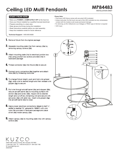
2d.
nuts (1b) provided in hardware package and place
driver (4a) inside canopy (2a)
6a.
9. Attach canopy (2a) to mounting plate (1c) with canopy screws (2b)
(1a) using junction box screws provided (1e) in hardware package
4. Thread connector (3a) into fixture (3b) to secure
5. Connect quick connectors (6a) together and attach rods (2d) by threading clockwise
ቤተ መጻሕፍቲ ባይዱ
1. Remove fixture from its original package
2. Separate mounting plate (1c) from canopy (2a) by removing canopy screws (2b)
3. Attach mounting plate (1c) to electrical junction box
Ceiling LED Multi Pendants
MP84483 INSTALLATION SHEET
START FROM HERE
• Make sure POWER is COMPLETELY OFF at the fuse box • Have your fixture installed by a qualified licensed electrician • Prepare everything in a clear area • Wear gloves at all times during this installation • Read instructions carefully before you start assembly • Keep this installation sheet for future reference
海康威视 FELCOM12 通信系统说明书

Tech Date Box 1 - FELCOM12 Display Wt: 24 lbs. Dim: 20"x 17"x 21"Part No.Description Quantity Yes Remarks 1IB581LCD Terminal Display with CPU 12000-138-599BTC-5100 PS/2 Keyboard 13000-055-405Blank Floppy Disk 1.44M 14004-437-270IB581 Software Floppy Disk 1updated periodically Box 2 - FELCOM12 Comm. Unit Wt: 27 lbs. Dim: 18"x 17"x 16"Part No.Description Quantity Yes Remarks 1IC212Communication Unit BDU 12000-802-080Tapping Screw 63000-861-937Knob Bolt 24004-437-990Hanger Assembly 15100-087-911Hanger Washer 26OME-561-30Z Operator's Manual 17OSE-561-30Z Operator's Guide 1Box 2 Con't. - FELCOM12 Antenna Unit "Part No.Description Quantity Yes Remarks 1IC112Antenna Unit Felcom 121Box 2 Con't. - FELCOM12PC Inst Kit Wt: 30 lbs. Dim: 13"x 13"x 28"Part No.Description Quantity Yes Remarks 1IC302Distress Alert Unit 22IC303Telex Indicator 1Not in FELCOM12PC 3000-108-138Ground Wire 1sub 000-043-2594000-112-543Power Cable 1"5000-127-108DB9-DB9 Cable 1"6000-802-084Tapping Screw 4"7100-217-010Label INMAR 1"8100-237-670Hook Loop Fastener 4"9100-237-680Hook Loop Fastener 4"10100-248-051Label Keyboard 1"11100-248-060Label CSD 1"12000-122-400Power Cable 1sub 004-438-00013000-508-663Conn SRCN6A16-10P 1"14590-300-310Copper Strap 1.2M 1"15000-802-080Tapping Screw 6sub 000-043-34416000-861-937Knob Bolt 2"17100-087-911Hanger Washer 2"18004-437-990Hanger Assembly 1"19000-108-424Crimp Lug FV2-33sub 004-438-010 (X 3)20000-508-662Conn SRCN6A16-7P 3"21000-538-113Crimp Lug FV1.25-315"22000-802-079Tapping Screw 3 x 1012"23000-802-393Hole Plug 3"24000-808-099Bushing 3"25100-208-272Distress Cover 2sub 000-041-294PACKING LIST FOR RC1515IC212IC112FELCOM12INST IB581/12Tech Date Box 2 Con't. - FELCOM12PC Installation Kit "Part No.Description Quantity Yes Remarks 26100-248-770Distress Label 2sub 000-041-29427Distress Alert Procedures 128Precautions-Inmarsat C Felcom12129Precautions-IC302130OSC-561-31Z Simple E-Mail Felcom10/11/12131Creating Internet Message 132Activation Registration Form 133IME-561-30Z Installation Manual 1Box 2 Con't. - Cable Wt: 14 lbs. Dim: 10"x 13"x 14"Part No.Description Quantity Yes Remarks 1000-138-86730M Coax Cable 150M available 2000-133-058Conn. N-P-5DFB-113000-139-927Cable Assembly 16S023814000-566-000Grounding Wire 15000-835-526Self Bounding Tape 16000-854-118Adhesive 17000-862-182Hex Bolt M6 x 12 SUS30418000-862-129Hex Bolt M6 x 16 SUS30449100-251-820Antenna Mounting Pipe 110*000-117-599*50M with 8D-FB-CV Conn.**sub for 30M Serial No.2560-Checked By:Box 3 - FS1562/15Wt: 32 lbs. Dim: 17"x 14"x 20"Part No.Description Quantity Yes Remarks 1FS1562/15DIS 250W SSB Radiotelephone 1w/ remote plug2OME-557-22Z Operator's Manual 13IME-557-22Z Installation Manual 14005-922-690Hanger 15000-800-601Knob Bolt 26100-087-911Hanger Washer 27100-100-390Knob Washer 28000-800-414Tapping Screw 69000-864-129Flat Washer 610000-139-033Microphone 111000-130-430Power Cable 112000-113-348Grounding Wire 113000-549-015Fuse/Glass 20A 1PACKING LIST FOR RC1515FELCOM12INST FS1562/15For Internal Use Only FELCOM12CBLTech Date Box 3 (con't)- AT1560"Part No.Description Quantity Yes Remarks 1AT1560250W Automatic Coupler 12000-113-360Coaxial RF Cable 10M 120M available 3000-130-484Coupler Control Cable w/ Connector 120, 30M available 4000-113-3482M Ground Wire 15000-130-472Rubber Pipe Seal 16000-805-494Tapping Screw M5x1647000-572-187Copper Strap 04S408011Serial No.3503 -Checked By:Box 4 - DP6 Modem Unit Wt: 13 lbs. Dim: 9"x 13"x 22"Part No.Description Quantity Yes Remarks 1DP-6NBDP Modem Unit 12OME-561-00Z Operator's Manual 13IME-561-00Z Installation Manual 14OSE-561-00Z Operator's Guide 15590-300-310Copper Strap 1.2M 16000-867-553Tapping Screw M5 x 2547000-864-128Flat Washer M548000-120-946DB25 Connector 29000-112-543Power Cable Assembly 3M 110000-508-663Connector SCRN6A16-10P 1Box 5 - DP6 LCD Terminal Wt: 24 lbs. Dim: 20"x 17"x 21"Part No.Description Quantity Yes Remarks 1IB581Monochrome LCD Terminal 1with DP6 on CPU 2000-138-599Mini Keyboard with Cable & Plug 13000-055-405Blank Floppy Disk 1.44M 1unformatted4004-447-090DP6 Software "Floppy Disk"15000-108-138Grounding Wire 2M 16000-112-543Power Cable Assembly 3M 17000-127-108Data Cable DB25-DB25 "5M"18000-802-084Tapping Screw M6 x 2049100-217-010BCM Label 110100-237-670Hook Loop Fastener 1411100-237-680Hook Loop Fastener 2412100-248-050Label 113100-248-060Label "Compass Safe Distance"1AT1560For Internal Use Only DP6MAIN IB581/6PACKING LIST FOR RC1515Tech Date Serial No.3516 - Checked By:Box 6 - DSC60 Terminal ReceiverPart No.Description Quantity Yes Remarks 1DSC60DSC Terminal / Watch Receiver 12OME-562-80Z Operator's Manual 13IME-562-80Z Installation Manual 14005-950-250Mounting Bracket 15005-948-710Mouunting Knob Assembly 2sub 005-950-1806000-800-414Tapping Screw M6 x 205"7000-864-129Flat Washer M65"8000-144-917External Speaker with Cord & Plug 1Serial No.2596 - Checked By:Box 7 & 8 - FM8500 (x 2)Wt: 17 lbs. Dim: 9"x 15"x 18"Part No.Description Quantity Yes Remarks 1FM8500Main Unit 12OME-560-30Z Operator's Manual 13IME-560-30Z Installation Manual 14Distress Alert Procedure 15000-138-000Handset Bracket Assembly 16100-274-720Distress button Cover Assembly 17000-108-368Plug FM14-4P 18000-111-537Plug FM14-5P 19000-116-185Plug FM14-6P 110000-113-345Plug FM14-7P 111000-500-346Plug HS16P-2112005-992-690Bracket Assembly 113000-800-601Knobs 214000-800-414Tapping Screw 6 6 x 2015000-864-129Flat Washer 6M616100-087-911Hanger Washer 217100-100-390Knob Washer 2on knob 18OSE-560-30Z Operator's Guide 1Serial No.1375 - Checked By:Box 9 & 10 - PP510 (x 2)Wt: 27 lbs. Dim: 18"x 17"x 16"Part No.Description Quantity Yes Remarks 1PP51024V Dot Matrix Printer 12PP5-100-002Paper Carriage Assy 13000-133-029Ribbon Cassette 14004-434-410Printer Fixtures (2pc)1sub 000-043-257FM8500For Internal Use Only DSC60For Internal Use Only For Internal Use Only PP510PACKING LIST FOR RC1515Tech Date Serial No.1375 - Checked By:Box 9 & 10 (con't) - PP510 (x 2)"Part No.Description Quantity Yes Remarks 5Carrier Mount 2"6Knurled Screws for Mounting 2"7Hook Loop Fastener Strip 2"8000-802-081Tapping Screw 4"9100-217-010"BCM" Sticker 1"10100-222-480"Compass Safe" Sticker 1"11000-132-249Power Cable Assy 112RC1-500-019Cable 6 ft. Centronics 36p>DB25113AYT214Roll Paper 114OME-508-00Z Operator's Manual 1Box 11 - PR850A Wt: 86 lbs. Dim: 16"x 20"x 20"Part No.Description Quantity Yes Remarks 1PR805A Rectifier AC to 24 VDC 1w/ auto switchover 2Label Voltage Selection (100-240V)13Lug Solder Type 24Lug Crimp 35Tapping Screw 66Washer Flat 67Voltage Alternation List 1Box (Crate) 12 - FUSA1500Wt: 296 lbs. Dim: 32"x 36"x 47"Part No.Description Quantity Yes Remarks 1FUSA1500A3 Pre-Wired Rack w/ meter 1with NMEA distributor 2Shore-Based Maintenance Certificate 1& incl mic bracket 3"E Meter" Owner's Manual 14IME-GMD-10Z Console Installation Manual 15RC1-500-034ATC Fuse 3A 36RC1-500-014Bulb 5W 24V 17RC1-500-060Connector PL2592FELCOM12KIT (Installed in IC212 - in Box 1)Part No.Description Quantity Yes Remarks 1006-969-200GPS Module GN74NNCC NE 12RF Mini Coax 138 pin VH Pigtail (to CPU J8)1rev 6/03PR850A FUSA1500FELCOM12KIT For Internal Use Only PP510PACKING LIST FOR RC1515。
IQC12电动阀说明书

IQC12电动阀说明书一、操作前的准备:1、操作阀门前,应认真阅读操作说明。
2、操作前一定要清楚气体的流向,应注意检查阀门开闭标志。
3、检查电动阀外观,看该电动阀门是否受潮,如果有受潮要作干燥处理;如果发现有其他问题要及时处理,不得带故障操作。
4、对停用3个月以上的电动装置,启动前应检查离合器,确认手柄在手动位置后,再检查电机的绝缘、转向及电气线路。
二、电动阀门操作注意事项:1、启动时,确认离合器手柄在相应位置。
2、如果是在控制室控制电动阀,把转换开关打大REMOTE位置,然后通过SCADA系统控制电动阀的开关。
3、如果手动控制,把转换开关打在LOCAL位置,就地操作电动阀的开关,电动阀开到位或者关到位的时候它会自动停止工作,最后把运行转换开关打到中间位置。
4、采用现场操作阀门时,应监视阀门开闭指示和阀杆运行情况,阀门开闭度要符合要求。
5、采用现场操作全关闭阀门时,在阀门关到位前,应停止电动关阀,改用微动将阀门关到位。
6、对行程和超扭矩控制器整定后的阀门,首次全开或全关阀门时,应注意监视其对行程的控制情况,如阀门开关到位置没有停止的,应立即手动紧急停机。
7、在开、闭阀门过程中,发现信号指示灯指示有误、阀门有异常响声时,应及时停机检查。
8、操作成功后应关闭电动阀门的电源。
9、同时操作多个阀门时,应注意操作顺序,并满足生产工艺要求。
10、开启有旁通阀门的较大口径阀门时,若两端压差较大,应先打开旁通阀调压,再开主阀:主阀打开后,应立即关闭旁通阀。
11、收发清管球(器)时,其经过的球阀必须全开。
12、操作球阀、闸阀、截止阀、蝶阀只能全开或全关,严禁作调节用。
13、操作闸阀、截止阀和平板阀过程中,当关闭或开启到上死点或下死点时,应回转1/2~1圈。
多参数监护仪说明书

说明书信息部件号:01.54.456438-10 发行时间:2014 年4 月版权©深圳市理邦精密仪器股份有限公司2014 声明本说明书为操作、保养和维修产品的参考资料。
用户应严格依照说明书内容操作,对于不按照说明书内容操作而造成的故障或事故,深圳市理邦精密仪器股份有限公司(以下简称“理邦仪器”)不负担任何法律责任。
理邦仪器拥有本说明书中所有内容的版权,未经本公司的明确书面许可,任何人不得照相复制、复印或翻译成其它语言。
本产品说明书包含受版权法保护的专有资料,包括但不限于技术秘密、专利信息等商业秘密,用户具有保密义务,不得向无关第三方披露本说明书中的任何内容。
用户持有本产品说明书并不表示理邦仪器对产品所含知识产权的授权许可。
本说明书的修改权、更新权及最终解释权均属于理邦仪器。
注册信息医疗器械生产企业许可证编号:粤食药监械生产许20010086 号粤制00000556 号产品注册证号:国食药监械(准)字2014 第3210404 号执行标准号:YZB/国0681-2014 产品名称:病人监护仪产品型号:iM50、iM60 、iM70、iM80制造商的责任理邦仪器仅在下列情况下才认为应对仪器的安全性、可靠性和性能负责,即:装配操作、扩充、重调、改进和维修均由理邦仪器认可的人员进行,相应房间的电气安装环境符合国家标准,以及仪器按照操作指导进行使用。
理邦仪器将在用户提出要求时有偿提供电路图及其它信息,以帮助用户由适当的、合格的技术人员来维修那些理邦仪器归类为可由用户维修的仪器部分。
本说明书的术语说明警告:针对可能造成人员伤亡的操作或情形。
小心:针对可能造成设备损坏、产生错误数据,或使过程失效的操作或情形。
注意:您应当了解的重要信息。
目录1 预期用途和安全信息 (1)1.1 预期用途 (1)1.2 安全信息 (1)1.3 监护仪上使用的符号的解释 (3)2 安装 (7)2.1 初始检查 (7)2.2 安装监护仪 (7)2.2.1 将监护仪置于水平台面上 (7)2.2.2 安装到墙上 (7)2.2.3 安装到台车上 (7)2.3 连接交流电源线 (7)2.4 检查监护仪 (8)2.5 检查记录仪 (8)2.6 设定日期与时间 (8)2.7 移交监护仪 (8)3 基本操作 (9)3.1 概况 (9)3.1.1 正面图 (9)3.1.2 背面图 (12)3.1.3 侧面图 (15)3.1.4 功能配置 (16)3.2 操作与浏览 (17)3.2.1 使用按键 (18)3.3.1 演示模式 (20)3.3.2 待机模式 (20)3.3.3 夜间模式 (20)3.4 更改监护仪设置 (20)3.4.1 调整屏幕亮度 (20)3.4.2 更改日期与时间 (21)3.5 调整音量 (21)3.5.1 设置键盘音量 (21)3.5.2 设置报警音量 (21)3.5.3 调整心跳音量 (21)3.6 检查监护仪版本 (21)3.7 联网监护 (21)3.8 设置语言 (22)3.9 了解屏幕 (22)3.10 触摸屏校准 (22)3.11 禁止触摸屏操作 (22)3.12 使用条形码扫描仪 (22)3.13 解决IBP 标名冲突 (23)4 报警 (24)4.1 报警分类 (24)4.1.1 生理报警 (24)4.1.2 技术报警 (24)4.1.3 提示信息 (24)4.2 报警级别 (24)4.3 报警控制 (25)4.3.1 设置参数报警 (25)4.3.2 报警音暂停 (26)4.3.3 静音 (26)4.5 探头脱落报警 (27)4.6 报警自检 (27)5 报警信息列表 (28)5.1 患者报警消息 (28)5.2 技术报警 (31)5.3 提示信息 (42)5.4 报警限范围 (43)6 管理病人 (48)6.1 接收病人 (48)6.1.1 病人类型和“起搏的”状态 (49)6.2 快速接收病人 (49)6.3 编辑病人资料 (49)6.4 更新病人 (49)6.5 中央监护系统 (50)7 用户界面 (51)7.1 设置界面风格 (51)7.2 选择参数 (51)7.3 更改波形 (51)7.4 更改界面布局 (51)7.5 观察趋势共存 (51)7.6 观察呼吸氧合图 (52)7.7 大字体界面 (52)7.8 它床观察 (52)7.8.1 打开它床观察窗口 (53)7.8.2 设置它床观察窗口 (53)7.11 默认配置 (54)8 监护ECG (55)8.1 概述 (55)8.2 安全信息 (55)8.3 ECG 显示 (56)8.3.1 更改ECG 波形大小 (56)8.3.2 更改ECG 滤波设定 (57)8.4 使用ECG 报警 (57)8.5 选择计算导联 (57)8.6 ECG 监护 (57)8.6.1 备皮以供粘贴电极 (57)8.6.2 连接心电图电缆 (58)8.7 选择导联类型 (58)8.8 安装电极 (58)8.8.1 3 导联的电极安放 (59)8.8.2 5 导联的电极安放 (59)8.8.3 12 导联的电极安放 (61)8.8.4 为外科患者推荐的ECG 导联连接 (62)8.9 ECG 菜单设置 (63)8.9.1 设置心率报警源 (63)8.9.2 智能导联脱落 (63)8.9.3 心跳音量 (64)8.9.4 ECG 监护类型 (64)8.9.5 设定起搏状态 (64)8.9.6 ECG 校准 (65)8.9.7 ECG 波形设置 (65)8.10 ST 分析 (65)8.10.2 ST 显示 (66)8.10.3 报警限设置 (66)8.10.4 确定ST 段分析点 (66)8.10.5 调整ISO、ST 测量点 (66)8.11 心律失常监护 (67)8.11.1 心律失常分析 (67)8.11.2 心律失常分析菜单 (68)8.12 12 导监护 (68)8.12.1 进入12 导监护界面 (68)8.12.2 12 导诊断回顾 (69)9 监护RESP (70)9.1 概述 (70)9.2 安全信息 (70)9.3 安放呼吸电极 (70)9.4 心脏重叠 (71)9.5 胸廓扩张 (71)9.6 腹式呼吸 (71)9.7 选择呼吸导联 (71)9.8 更改计算类型 (71)9.9 更改波形 (72)9.10 使用“呼吸”报警 (72)9.11 设置窒息报警时间 (72)10 监护SpO2 (73)10.1 概述 (73)10.2 安全信息 (73)10.3 SpO2 测量 (74)10.4 测量步骤 (74)10.6 调整报警限 (75)10.7 将SpO2/Pleth(体积描记)设为脉搏源 (75)10.8 设置脉搏调制音 (75)10.9 设置灵敏度 (75)10.10 SI(信号强度) (76)11 监护PR (77)11.1 概述 (77)11.2 设置PR 来源 (77)11.3 设置脉搏音量 (77)11.4 使用脉搏报警 (77)11.5 选择处于活动的报警源 (77)12 监护NIBP (78)12.1 概述 (78)12.2 安全信息 (78)12.3 介绍NIBP 测量 (79)12.4 测量的限制 (79)12.5 测量模式 (79)12.6 测量步骤 (80)12.7 操作提示 (80)12.8 肢体与心脏不在同一水平高度时对测量的修正 (81)12.9 NIBP 报警 (81)12.10 NIBP 复位 (81)12.11 NIBP 校准 (81)12.12 漏气检测 (82)12.12.1 漏气检测过程 (82)13 监护TEMP (84)13.1 概述 (84)13.2 安全信息 (84)13.3 温度测量设置 (84)13.4 计算温差 (84)14 监护IBP (85)14.1 概述 (85)14.2 安全信息 (85)14.3 监护步骤 (85)14.4 选择监护的压力 (86)14.5 压力传感器校零 (86)14.6 压力测量校零 (87)14.7 压力校零故障排除(以Art 为例说明) (87)14.8 IBP 压力校准 (87)14.9 压力校准故障排除 (89)14.10 IBP 报警 (89)14.11 更改IBP 波形标尺 (89)15 监护CO2 (90)15.1 概述 (90)15.2 安全信息 (90)15.3 监护步骤 (91)15.3.1 传感器校零 (91)15.3.2 旁流CO2 模块测量设置 (91)15.3.3 主流CO2 模块测量设置 (93)15.4 设置CO2 波形 (95)15.5 修正CO2 (95)15.7 设置窒息报警延迟 (96)16 监护AG (97)16.1 概述 (97)16.2 安全信息 (97)16.2.1 旁流式麻醉模块的安全信息 (97)16.2.2 主流式麻醉模块的安全信息 (99)16.3 监护步骤 (100)16.3.1 旁流式的监护步骤 (100)16.3.2 主流式的监护步骤 (102)16.4 设置窒息报警时间 (106)16.5 旁流式麻醉模块的工作状态 (106)16.6 主流式麻醉模块的工作状态 (106)16.7 O2 补偿 (107)16.8 湿度影响 (107)17 冻结 (108)17.1 概述 (108)17.2 冻结状态的进入与退出 (108)17.2.1 进入冻结状态 (108)17.2.2 退出冻结状态 (108)17.3 冻结波形回顾 (109)18 回顾 (110)18.1 趋势图回顾 (110)18.1.1 挑选不同参数的趋势图显示 (110)18.1.2 调节幅度 (110)18.1.3 设定分辨率 (111)18.1.4 移动图形 (111)18.1.5 切换到趋势表 (111)18.1.6 在记录仪上输出趋势曲线 (111)18.2.1 设置分辨率 (111)18.2.2 移动图形 (111)18.2.3 切换到趋势图 (112)18.2.4 在记录仪上输出趋势表 (112)18.3 NIBP 回顾 (112)18.3.1 移动图形 (112)18.3.2 在记录仪上输出NIBP 回顾数据 (112)18.4 报警事件回顾 (112)18.4.1 移动图形 (112)18.4.2 选择特定参数的报警事件回顾 (112)18.4.3 设置时间索引 (113)18.4.4 在记录仪上输出报警事件回顾 (113)18.5 12 导诊断回顾 (113)18.5.1 删除分析结果 (113)18.5.2 诊断结果与波形之间的切换 (114)18.5.3 在记录仪上输出波形或分析结果 (114)19 计算和滴定表 (115)19.1 药物计算 (115)19.1.1 计算步骤 (115)19.1.2 计算单位 (116)19.2 滴定表 (116)19.3 血液动力学计算 (117)19.3.1 计算步骤 (117)19.3.2 输入参数 (117)19.3.3 输出参数 (117)20 记录 (119)20.1 记录仪的一般资料 (119)20.2 记录仪性能 (119)20.3 记录类型 (120)20.5 记录仪操作及状态信息 (121)21 其它功能 (124)21.1 护士呼叫 (124)21.2 无线网络 (124)21.3 在可移动存储设备上进行数据存储 (124)22 电池 (127)22.1 电池灯 (127)22.2 主屏幕上的电池状态信息 (127)22.3 检查电池性能 (127)22.4 更换电池 (128)22.5 电池回收 (129)22.6 电池的保养 (129)23 保养与清洁 (130)23.1 概述 (130)23.2 清洁 (130)23.3 消毒 (133)23.4 对其他附件进行清洁及消毒 (135)24 维护 (136)24.1 检查 (136)24.2 维护计划 (136)25 保修及售后服务 (137)25.1 保修 (137)25.2 售后服务 (137)26 电子信息产品污染控制 (138)26.1 标识 (138)26.2 有毒有害物质或元素的名称及含量 (138)27.1 ECG 附件 (139)27.2 SpO2 附件 (141)27.3 NIBP 附件 (141)27.4 TEMP 附件 (142)27.5 IBP 附件 (142)27.6 CO2 附件 (142)27.7 GAS 附件 (144)27.8 其它附件 (145)A 产品规格 (146)A.1 监护仪类型 (146)A.2 监护仪规格 (146)A.2.1 物理规格 (146)A.2.2 工作环境 (146)A.2.3 显示器规格 (147)A.2.4 电池 (148)A.2.5 记录仪 (148)A.2.6 数据存储 (149)A.3 ECG 规格 (149)A.4 RESP 规格 (153)A.5 NIBP 规格 (154)A.6 SpO2 规格 (155)A.7 TEMP 规格 (155)A.8 IBP 规格 (156)A.9 CO2 规格 (157)A.10 AG 规格 (160)A.10.1 旁流 (160)A.10.2 主流 (163)B EMC 测试等级申明-指南和制造商的声明 (166)B.1 电磁发射 (166)B.2 电磁抗扰度 (166)B.3 电磁抗扰度 (167)B.4 推荐隔离距离 (169)C 出厂默认设置 (170)C.1 病人信息 (170)C.2 报警 (170)C.3 ECG (170)C.4 RESP (172)C.5 SpO2 (172)C.6 PR (172)C.7 NIBP (173)C.8 TEMP (173)C.9 IBP (174)C.10 CO2 (174)C.11 AG (175)D 术语一览表 (177)1 预期用途和安全信息1.1 预期用途产品性能结构以及组成:该产品由主机、相应功能附件(心电电缆、无创血压袖套、血氧传感器、体温传感器、二氧化碳气体测量组件、麻醉气体测量组件)组成。
恒力电器12V无线剪刀操作手册说明书

12V CORDLESS PRUNER OPERATING MANUALSPECIFICATIONSBatteries......................................................12V DC Pole length.......................................................4 Ft.Overall length...................................................6 Ft.Max. cutting diameter......................................15/16"Weight ..........................................................4.4 lbsINTENDED USEThe cordless pruner can be used for the following applications only:Limbing and pruning branches from trees. (Max. diameter 15/16")Picking fruit from trees.WARNING: DO NOT CUT OTHER MATERIAL SUCH AS WIRE, STEEL WIRE, STONE,PLASTIC, AND SO ON.EXPLANATION OF SAFETY SYMBOLSSAFETY INSTRUCTIONSKnow your toolWARNING! Carefully observe the instructions in this manual to reduce the risk of personal injury or material damage.• Read all of this manual carefully before operating the tool.• Before operating the tool, make sure that you know how to switch the tool off in an emergency.• Retain this manual for future reference .GENERAL SAFETY RULESWARNING! Read all instructions. Failure to follow all instructions listed below may result in electric shock, fire and/or serious injury. The term “power tool” in all of the warnings listed below refers to your battery operated (cordless) power tool.SAVE THESE INSTRUCTIONS1) Work area a) Keep work area clean and well lit. Cluttered and dark areas invite injuries.b) Do not operate power tools in explosive atmospheres, such as in the presence of flammable liquids, gases or dust. Power tools create sparks which may ignite the dust or fumes.c) Keep children and bystanders away while operating a power tool. Distractions can cause you to lose control.- Warning!- Read the instruction manual before use - Do not use in rain or wet conditions.- Always wear eye protection, muffler and helmet.2) Electrical safetya) Avoid body contact with grounded surfaces such as pipes, radiators, ranges andrefrigerators. T here is an increased risk of electric shock if your body is grounded.b) Do not expose power tools to rain or wet conditions. Water entering a power tool willincrease the risk of electric shock.3) Personal safetya) Stay alert, watch what you are doing and use common sense when operating apower tool. Do not use a power tool while tired or under the influence of drugs, alcohol or medication. A moment of inattention while operating power tools may result in serious personal injury.b) Use safety equipment. Always wear eye protection. Safety equipment such as dustmask, non-skid safety shoes, hard hat, or hearing protection used for appropriate condi-tions will reduce personal injuries.c) Avoid accidental starting. Ensure the switch is in the off position before pluggingin. Do not carry the power tool with your finger on the switch.d) Remove any adjusting key or wrench before turning the power tool on. A wrench ora key left attached to a rotating part of the power tool may result in personal injury.e) Do not overreach. Keep proper footing and balance at all times. This enables bettercontrol of the power tool in unexpected situations.f) Dress properly. Do not wear loose clothing or jewelry. Keep your hair, clothing and gloves away from moving parts. Loose clothes, jewelry or long hair can be caught in moving parts.g) If devices are provided for the connection of dust extraction and collection facili-ties, ensure these are connected and properly used.4) Power tools use and carea) Do not force the power tool. Use the correct power tool for your application. Thecorrect power tool will do the job better and safer at the rate for which it was designed.b) Do not use the power tool if the switch does not turn it on and off. Any power toolthat cannot be controlled with the switch is dangerous and must be repaired by anauthorized service center.c) Disconnect the battery pack from tool and make sure trigger is in the locked offposition. Such preventive safety measures reduce the risk of starting the power tool accidentally.d) Store idle power tools out of the reach of children and do not allow persons unfa-miliar with the power tool or these instructions to operate the power tool. Power tools are dangerous in the hands of untrained users.e) Maintain power tools. Check for misalignment or binding of moving parts, break-age of parts and any other condition that may affect the power tools operation. If damaged, have the power tool repaired before use. Many accidents are caused by poorly maintained power tools.f) Keep cutting tools sharp and clean. Properly maintained cutting tools with sharp cuttingedges are less likely to bind and are easier to control.g) Use the power tool, accessories and tool bits etc., in accordance with theseinstructions and in the manner intended for the particular type of power tool, tak-ing into account the working conditions and the work to be performed. Use of the power tool for operations different from intended could result in a hazardous situation.5) Battery tool use and carea) Ensure the switch is in the off position before inserting battery pack. Inserting thebattery pack into power tools that have the switch on invites accidents.b) Recharge only with the charger specified by the manufacturer.A charger that issuitable for one type of battery pack may create a risk of fire when used with another battery pack.c) Use power tools only with specifically designated battery packs. Use of any otherbattery packs may create a risk of injury and fire.d) When battery pack is not in use, keep it away from other metal objects like paperclips, coins, keys, nails, screws, or other small metal objects that can make aconnection from one terminal to another. Shorting the battery terminals together may cause burns or a fire.e) Under abusive conditions, liquid may be ejected from the battery; avoid contact. Ifcontact accidentally occurs, flush with water. If liquid contacts eyes, additionally seek medical help. Liquid ejected from the battery may cause irritation or burns.6) Servicea) Have your power tool serviced by a qualified repair person using only identicalreplacement parts. This will ensure that the safety of the power tool is maintained. ADDITIONAL SAFETY INSTRUCTIONS FOR BATTERIES AND CHARGERSBatteries• Never attempt to open for any reason• Do not expose to water• Do not incinerate the battery pack even if it is severely damaged or is completely worn out. The battery pack can explode in a fire.• Do not store in locations where the temperature may exceed 104°F.• Do not leave the battery pack in the charger when the charging is finished, otherwise battery leakage may occur.• Charge only at room temperature.• Charge only at using the charger provided with the tool (see technical data)• Before charging, make sure that the battery is dry and clean.• Use only the correct type of battery for the tool(see technical data).• Dispose of batteries properly by following the recycling options in your community. Do not put battery into a fire.• Under extreme conditions, battery leakage may occur. When you notice liquid on the battery, proceed as follows:• Carefully wipe the liquid off using a cloth. Avoid skin contact.• In case of skin or eye contact, follow the instructions below.The battery fluid, a 25-30% solution of potassium hydroxide, can be harmful. In case of skin contact, immediately rinse with water. In case of eye contact, rinse abundantly with clean water for at least 10 minutes. Consult a physician.NOTE:The batteries in your battery charger are the nickel-cadmium type. The batteries are Ni-Cd; cadmium is considered to be a toxic material by the Environmental Protection Agency. Before disposing of damaged or worn out Nickel-Cadmium battery packs, check with your local Environmental Protection Agency to find out about special restrictions on the disposal of these battery packs or return them to a certified service center for recycling.Chargers• Charger's plug must match the outlet. Never modify the plug in any way. Unmodified plugs and matching outlets will reduce risk of electric shock.• Use your charger only to charge batteries of the type supplied with your tool.Other batteries could burst, causing personal injury and damage.• Only 2 battery packs is allowed to be charged continuously in order to prevent overheating of charger, necessary rest time is required to let the charger cool down before further charging.• When charging is finished, unplug the charger from outlet and remove the battery pack from the charger. Do not leave the battery pack in the charger.• Never carry the charger by its cord or pull it to disconnect from the socket. Keep the cord away from heat, oil and sharp edges.• Never attempt to charge non-rechargeable batteries.• The cord of charger is not changeable; do not continue to use if the cord is damaged.• Do not expose to water or rain, and not use in wet condition.• Do not open the charger.• Do not probe the charger.• Intended for indoor use only.ADDITIONAL SAFETY INSTRUCTIONS FOR PRUNER Wear safety goggles and a hard hat when operating this tool.Wear anti-slip gloves when operating this tool.Do not expose the tool to rain or high humidity.• THIS TOOL CAN CAUSE SERIOUS INJURIES. Read instructions carefully for the correct handling, preparation, maintenance, starting and stopping of the tool. Be familiar with all controls and proper use of the tool.• Only use the tool in daylight or good artificial light.• Never allow children to use the tool.• Never stand directly beneath the limb you are cutting.• Beware of overhead power lines! Do not use within 50 feet of overhead power lines.• Avoid operating while people, especially children are nearby.• Dress properly! Do not wear loose clothing or jewelry which can be caught in moving parts. Use of sturdy gloves, non-skid footwear, and safety glasses is recommended;• If the tool stalls, immediately switch it off. Remove the battery before attempting to remove any obstructions.• Remove the battery before checking, maintenance or working on the tool.• While operating the tool be always sure of a safe and secure operating position especially when using steps or a ladder.• Do not operate the tool with a damaged or excessively worn cutting device.• Always wear ear protection, goggle and helmet during operating.• Always ensure that all guards are fitted when using the tool. Never attempt to use an incomplete tool or a tool with unauthorized modifications.• Always use two hands to operate the tool.• When transporting or storing the tool always fit the blade sheath.• Always be aware of your surroundings and stay alert for possible hazards that you may not hear due to the noise of the tool.• Do not carry the tool with your hands on the switch unless the battery has been removed.• If you have not used a pruner before, preferably seek practical instruction by an experi-enced user in addition to studying this manual.• Never touch the blades while the tool is running or when the battery pack is installed.• Never attempt to force the blades to come to a standstill.• Do not put the tool down until the blade have come to a complete standstill.• Regularly check the blades for damage and wear. Do not use the machine when the blades are damaged.• Take care to avoid hard objects (e.g. metal wire, railings) when pruning. Should you accidentally hit any such object immediately switch the tool off and check for any damage. • Should the tool start to vibrate abnormally, immediately switch it off and check for any damage.• Always be aware of falling debris when cutting the higher tree or hedge.• Be aware of the cutting blade, always wear gloves to protect your hands from cut.OPERATION (Fig. 1)1.Install the battery pack.2. Choose the branch you want to cut, press and hold the lock-off button(5) and switch trigger(6).3.Release the trigger to open the blades.Follow Steps 2 and 3 to cut branches continuously.Fitting and removing the batteryYour pruner is equipped with a battery pack, which powers the unit.To fit battery pack 1. Place battery pack in your pruner. Align raised rib on battery pack with groove inside pruner. See Fig1.2. Make sure the latches on each side of your battery pack snap in place and battery pack secured in pruner before beginning operation.To remove battery pack 1. Locate latches on end of battery pack and depress to release button(7) from your pruner.2. Remove battery pack from your pruner. 1. Blade 2. Connecting tube3. Assistant handle4. Body5. Lock-off button6. Switch trigger7. Release button8. Battery packFig. 1CHARGING THE BATTERY(Fig. 2)• The battery needs to be charged before Array first use and whenever it fails to producesufficient power on jobs that were easilydone before. When charging the batteryfor the first time, or after prolongedthe battery will attain full capacity.The battery may become warm whilecharging, this is normal and does notindicate a problem .• Remove it from the tool and insert it intothe charge station (2). The battery pack(1)will only fit into the charge in one way.Do not force. Be sure that battery is fullyseated in the charger.• Your battery can be charged in the 7-10hours charger supplied. Be sure to read all safety instructions before using your charger. This product is not user serviceable. There are no user serviceable parts inside the charger. Servicing at an authorized service center is required to avoid damage to static sensitive internal components.• Read all of the instructions in the battery charger section of this manual before attempting to charge the battery pack for your tool. Always use correct battery pack (pack supplied with tool or replacement pack exactly like it). Never install any other battery pack — it will ruin your tool and may create a hazard.1. Charging procedureThese chargers require no adjustment and are designed to be as easy as possible to operate. Simply place your battery pack into the receptacle of a plugged in charger and it will automatically charge the pack.(1). Connect the transformer (5) to the charger station (2).(2). Plug the transformer into an appropriate AC power outlet. The green LED (POWER)(4)lights to tell you that the charger is ready for use.(3). Insert the battery pack into the charger, as shown in Fig 2, making sure the pack is fullyseated in the charger. The red LED (CHARGE) (3) lights to tell you that the battery pack is on charge.(4). The battery pack will be fully charged in about 7 hours.2. Important charging notes.Longest life and best performance can be obtained if the battery pack is charged when the air temperature is between 64–75°F. Do not charge the battery pack in a very low or very high air temperature. This is important and will prevent serious damage to the battery pack.(1). The charger and battery pack may become warm to touch while charging. This is anormal condition, and does not indicate a problem.(2). Use the charger in normal room temperatures whenever possible. T o prevent overheating,do not cover the charger and do not charge battery packs in direct sunlight or near heat sources.(3). If the battery pack does not charge properly:(a). Check current at receptacle by plugging in a lamp or other appliance.(b). Move charger and battery pack to a location where the surrounding air temperatureis approximately 64–75°F.(c). If charging problems persist, take or send the tool , battery pack and charger to yourlocal service center.(4). The battery pack should be recharged when it fails to produce sufficient power on jobswhich were easily done previously. DO NOT CONTINUE to use under these conditions.Follow the charging procedure. You may also charge a partially used pack whenever you desire with no adverse affect on the battery pack.(5). Under certain conditions, with the charger plugged in to the power supply, the exposedcharging contacts inside the charger can be shorted by foreign material. Foreign materi-als of a conductive nature such as, but no limited to, steel wool, aluminum foil, or any buildup of metallic particles should be kept away from charger cavities. Always unplug the charger from the power supply when there is no battery pack in the cavity. Unplug charger before attempting to clean.(6). Do not immerse charger in water or any other liquid.WARNING!Don't allow any liquid to get inside charger. Electric shock may result. To facilitate the cooling of the battery pack after use, avoid placing the charger or battery pack in a warm environment such as in a metal shed, or an uninsulated trailer.CAUTION!Never attempt to open the battery pack for any reason. If the plastic housing of the battery pack breaks or cracks, return to a service center for recycling, do not put it into further use.MAINTENANCE1. Clean the blades using a soft brush.2. Clean the machine body using a dry cloth. (Do not use petrol or other solvent to clean body.)3. The part arrowed should be lubricated after using each time.4. The product should be kept in box. (Store the box in hight position that children cannot touch.)。
称重控制仪表说明书QDI-12K

QDI-12K选别控制器用户操作手册2007.03版上海秋豪衡器有限公司Shanghai queenhan Scales Co., Ltd.沪制00000312QDI-12K选别控制器目 录第一章 概述 ------------------------------------------ (3) 第二章 系统配置框图 ----------------------------------- (3) 第三章 主要功能和技术指标--------------------------------- (3) 第四章 外形尺寸及面板布置图 ----------------------------------- (4) 第五章 接口 ----------------------------------- (4) §1 传感器接口 -------------------------------------- (4) §2 输入/输出接口 -------------------------------------- (4) §3 串行接口 -------------------------------------- (5) 第六章 标定 -------------------------------------- (5) §1 称量基本参数设置 -------------------------------------- (5) §2 标定 -------------------------------------- (5) §3 A/D值显示 -------------------------------------- (5) 第七章控制方式及辅助参数设定----------------------------------- (5) §1 控制方式设定 -------------------------------------- (5) §2 辅助控制参数设定 -------------------------------------- (6) 第八章重量设定及配方存入和调用--------------------------------- (6) §1 重量设定 -------------------------------------- (6) §2 配方存入 -------------------------------------- (6) §3 配方调用 -------------------------------------- (6) 第九章其他操作 -------------------------------------- (7) §1 置零 -------------------------------------- (7) §2 去皮 -------------------------------------- (7) §2-1实物去皮 -------------------------------------- (7) §2-2皮重清除 -------------------------------------- (7) §2-3数字去皮 -------------------------------------- (7) §3 累计次数显示 -------------------------------------- (7) §4 查询 -------------------------------------- (7) §5 时间/日期的显示和设定----------------------------------- (7) §6 启动 ------------------------------------- ( 7) §7 停止 -------------------------------------- (7) §8 标准RS232输出格式 -------------------------------------- (8) 第十章维护保养及注意事项 -------------------------------------- (8) 附控制时序图 ---------------------------------------------------------------------- (9)QDI-12K选别控制器适用各种选别控制。
最新QDI_12使用说明书

QDI-12 称重显示控制器用户操作手册(包装秤,灌装秤控制仪)UEr12.52015.8版本产品执行标准:Q/IQWU 1-2013云南迅捷电子设备有限公司QDI-12称重显示控制器目录第一章概述------------------------------------ (3)第二章系统配置框图 -------------------------- (3)第三章主要功能和技术指标 ---------------------- (3)第四章外形尺寸及面板布置图、电源接线图--------------- (4)第五章接口---------------------------------------- (4)§1 传感器接口------------------------------------ (4)§2 输人/输出接口--------------------------------- (4)§3 串行接口------------------------------------ (5)第六章控制方式及辅助参数设定 ---------------------- (6)§1 控制方式设定------------------------------ (6)§2 辅助控制参数设定-------------------------- (6)第七章重量设定及配方存入和调用------------------------ (7)§1 重量设定-------------------------- (7)§2 配方存入--------------------------- (7)§3 配方调用--------------------------- (7)第八章其他操作----------------------------- (7)§1 置零----------------------------- (7)§2 去皮----------------------------- (8)§2-1实物去皮----------------------------- (8)§2-2皮重清除----------------------------- (8)§3 累计次数显示-------------------------- (8)§4 时间/日期的显示和设定 ----------------------- (8)§5 放料----------------------------- ( 8)§6 加料------------------------------ (8)§7 停止----------------------------- (8)§8 减法计量方式下上料的启动 ---------------------- (8)§9 标准RS232输出格式 ---------------------------- (9)第九章维护保养及注意事项 --------------------------- (9)第十章标定 ---------------------------- (5)§1 称量基本参数设置 ---------------------------- (5)§2 标定------------------------------------------ (5)§3 A/D值显示----------------------------------- (5)附录第一章概述QDI-12称重显示控制器适用定值控制,双显示、显示设定值和加料值、快速A/D转换器及智能数字滤波器技术、抗干扰能力强,快速稳定、多种控制模式和多项控制参数设定,可广泛应用于包装和配料系统及减法计量场合。
青岛啤酒D-12质量管理手册--
天津市顺地电动车自行车有限公司电动自行车文件编号:QM-01A版质量管理手册编制:审核:批准:2003年月日发布2003年月日实施目录前言 (1)1 范围 (1)2 引用标准 (1)3 术语和定义 (1)4 质量管理职责 (1)4.1 组织机构、管理职责 (1)4.2岗位职责权限 (2)4.3质量方针和质量目标 (5)5 生产资源提供 (9)6 文件和记录管理 (10)7 采购控制 (10)8 过程质量控制 (11)9 产品质量检验 (12)10 文明安全生产 (14)11 其他要求 (14)12 质量手册修改记录 (15)前言质量管理手册是描述本企业质量管理体系的文件,由总经理(厂长)审核、批准。
它是全体员工的行为准则,各部门都应严格按照其规定执行。
本手册按文件管理规定进行管理,未经批准不得借阅或复制给本企业以外人员。
本手册按总经理正式批准的日期实施。
1 范围本手册适用于企业生产电动自行车系列产品的质量管理。
也可用于换(发)生产许可证工厂生产条件审查及质量体系认证参考。
2 引用标准本手册参考GB/T 19001-2000质量管理体系要求、GB 17761-1999 电动自行车通用技术条件3 术语和定义本手册采用GB/T 19001-2000质量管理体系要求、GB 17761-1999 电动自行车通用技术条件中的术语和定义。
4 质量管理职责依据电动自行车质量管理和生产管理基本需要,从保证安全、质量而提出和规定组织结构和管理职责。
4.1 组织机构、管理职责本企业为有效实施管理,设置精干、高效、统一的组织结构,规定领导和各职能部门和人员的岗位职责和权利,保证生产和质量工作有序实施管理。
- 1、下载文档前请自行甄别文档内容的完整性,平台不提供额外的编辑、内容补充、找答案等附加服务。
- 2、"仅部分预览"的文档,不可在线预览部分如存在完整性等问题,可反馈申请退款(可完整预览的文档不适用该条件!)。
- 3、如文档侵犯您的权益,请联系客服反馈,我们会尽快为您处理(人工客服工作时间:9:00-18:30)。
QDI-12 称重显示控制器用户操作手册(包装秤,灌装秤控制仪)UEr12.52015.8版本产品执行标准:Q/IQWU 1-2013云南迅捷电子设备有限公司QDI-12称重显示控制器目录第一章概述------------------------------------ (3)第二章系统配置框图 -------------------------- (3)第三章主要功能和技术指标 ---------------------- (3)第四章外形尺寸及面板布置图、电源接线图--------------- (4)第五章接口---------------------------------------- (4)§1 传感器接口------------------------------------ (4)§2 输人/输出接口--------------------------------- (4)§3 串行接口------------------------------------ (5)第六章控制方式及辅助参数设定 ---------------------- (6)§1 控制方式设定------------------------------ (6)§2 辅助控制参数设定-------------------------- (6)第七章重量设定及配方存入和调用------------------------ (7)§1 重量设定-------------------------- (7)§2 配方存入--------------------------- (7)§3 配方调用--------------------------- (7)第八章其他操作----------------------------- (7)§1 置零----------------------------- (7)§2 去皮----------------------------- (8)§2-1实物去皮----------------------------- (8)§2-2皮重清除----------------------------- (8)§3 累计次数显示-------------------------- (8)§4 时间/日期的显示和设定 ----------------------- (8)§5 放料----------------------------- ( 8)§6 加料------------------------------ (8)§7 停止----------------------------- (8)§8 减法计量方式下上料的启动 ---------------------- (8)§9 标准RS232输出格式 ---------------------------- (9)第九章维护保养及注意事项 --------------------------- (9)第十章标定 ---------------------------- (5)§1 称量基本参数设置 ---------------------------- (5)§2 标定------------------------------------------ (5)§3 A/D值显示----------------------------------- (5)附录第一章概述QDI-12称重显示控制器适用定值控制,双显示、显示设定值和加料值、快速A/D转换器及智能数字滤波器技术、抗干扰能力强,快速稳定、多种控制模式和多项控制参数设定,可广泛应用于包装和配料系统及减法计量场合。
由于采用了内部控制精度高于显示精度10倍的方式、使控制精度大大提高,而稳定性又很好,千分之一精度由万分之一技术保障,自动去皮和自动修正方式可选择,以适用于各种不同场合。
可储存10个配方。
QDI-12采用嵌入式结构,铝合金外壳,抗干扰能力强。
操作简单,是各种定值包装和配料秤的理想控制仪表。
备有RS-485接口、可多台仪表组合成集散控制系统。
第二章系统配置框图加法有料斗计量方式加法无料斗计量方式减法无料斗计量方式第二章主要功能和技术指标1)、型号:QDI-12称重显示控制器2)、等级:3 级分度数n=30003)、双CPU结构,掉电数据保护。
4)、可储存10个配方。
5)、0.56"(字高14.2mm)双六位超高亮LED显示器。
6)、启动、停止、加料允许、放料允许输入信号(触点或集电极开路)。
7)、6个触点输出信号(220V/1A)。
8)、电源(220V,50Hz)。
9)、工作温度-10℃ - +40℃,湿度<90%。
10)、A/D转换速度:> 100次/秒,分辨率100000。
11)、传感器供桥电压:+5V, 可驱动350欧传感器8个。
12)、零点温度漂移:<0.1uv/℃。
13)、量程温度系数:<10 ppm/℃。
14)、传感器灵敏度范围:0.5mv/v - 4.0mv/v。
15)、零位调整能力:100% F.S.。
第四章 外形尺寸及面板布置图18692100200220电源连接图第五章 接口§1 传感器接口,采用 D-SUB-9(孔)插座。
各引脚说明如下:1). 传感器正端反馈2). 传感器正电源3). 屏蔽地4). 传感器负电源5). 传感器负端反馈7). 传感器正输入8). 传感器负输入§2 输入(6芯插座)接口,各引脚说明如下:1) 启动/夹袋 12) 结束/停止 23) 加料允许 34) 放料允许 45) +12V 56) 信号地 6§3 输出(8芯插座)接口,各引脚说明如下:1) 快加(快放) 12) 慢加(慢放) 23) 放料(上料) 34) 夹袋 45) 加料结束 56) 放料结束 67) 报警 78) 公共端 8报警◎ QDI-12称重显示控制器自动◎ 快加◎ 慢加◎放料◎ 去皮◎ 零位◎§4串行接口采用D-SUB-9(针)插头,各引脚说明如下:2). RS232-RXD3). RS232-TXD5). GND(仪表必须有良好的接地)7). RS485-A8). RS485-B第六章控制方式及辅助参数设定§1 控制方式设定在正常称重显示状态,按〖密码〗键,显示[ PS 0 ],键入密码〖101〗,按〖输入〗键,显示[ F abcde ],各参数说明如下:符号位数值说明a 012上显示窗显示设定重量上显示窗显示累计次数上显示窗显示料斗内重量b 0123加法有料斗、无夹袋控制的计量方式。
加法有料斗、有夹袋控制的计量方式。
加法无料斗、有夹袋控制的计量方式。
减法、有夹袋控制的计量方式。
c 01自动修正禁止。
自动修正允许。
d 01快加时,慢加不投入。
快加时,慢加投入。
e 01加料/放料允许,触发动作。
加料/放料允许,长时动作。
根据实际工作情况,设定各参数,设定后,按〖输入〗键,返回称重显示。
§2 辅助控制参数设定必须控制方式及辅助参数设定操作一次后,才能进行辅助控制参数设定。
显示操作说明称重显示辅助在正常称重显示状态,按〖辅助〗键↓t1 0.0 快加开启t1时间内,不作重量控制,以避免因快加开启的冲击,造成误动作。
↓输入根据需要,键入相应值后,按〖输入〗键。
t2 0.6 快加关闭后t2时间内,不作重量控制,以避免因快加关闭的冲击,造成误动作。
↓输入根据需要,键入相应值后,按〖输入〗键。
t3 0.8 慢加关闭,延迟t3时间后,进行自动累计,自动修正。
以避免因慢加关闭的冲击,造成计量误差。
↓输入根据需要,键入相应值后,按〖输入〗键。
t4 1.2 过放料时间,放料时重量< 零区t4时间后,关闭放料信号。
↓输入根据需要,键入相应值后,按〖输入〗键。
t5 0.8 放料关闭(或夹袋动作),延迟t5时间后,进行自动去皮,以避免因放料关闭的冲击,造成计量误差。
↓输入根据需要,键入相应值后,按〖输入〗键。
t6 2.0 超差报警时,报警输出t6时间,自动进入下一步控制。
↓输入根据需要,键入相应值后,按〖输入〗键。
t7 0.2 慢加关闭后, 在非自动修正周期代替t3延迟↓输入根据需要,键入相应值后,按〖输入〗键。
表一1 各种控制方式下信号和参数的含义第七章重量设定及配方存入和调用§§2 配方存入在正常称重显示状态,按〖密码〗键,显示[ PS 0 ],此时按〖设定〗键。
显示[ StAB-0 ],此时按0-9数字键,可将当前重量设定值和慢加关闭提前量存入0-9对应配方表中,按〖输入〗键,存入,返回称重显示。
§3 配方调用在正常称重显示状态,按〖密码〗键,显示[ PS 0 ],此时按〖辅助〗键。
显示[ CtAB-0 ],此时可按0-9数字键,可将对应配方表中重量设定值和慢加关闭提前量调出,作为当前重量设定值,按〖输入〗键,调用,返回称重显示。
第八章其他操作§1 置零在正常称重显示状态,称量稳定且<2%FS,按〖置零〗键,将显示置零,同时[ 零位]指示灯亮。
§2 去皮在正常称重显示状态,[ 去皮]指示灯熄灭状态,称量稳定且>0,按〖去皮〗键,将当前重量值作为皮重储存,显示置零,同时[ 去皮]指示灯点亮,显示净重。
在正常称重显示状态,[ 去皮]指示灯点亮状态,按〖去皮〗键,将皮重清除,[ 去皮]指示灯熄灭,显示毛重。
§3 累计次数显示在正常称重显示状态,按〖累计〗键,显示累计数[ n 68 ]。
再按〖累计〗键,上显示窗累计重量高四位[H 12 ],下显示窗累计重量低四位,[ L 310.6 ],累计重量为12310.6。
在上述显示过程中,按〖打印〗键将累计值打印出来。
在上述显示过程中,按〖清除〗键,清除累计值,按〖输入〗键,返回称重显示。
§4 时间/日期的显示和设定§4-1 在正常称重显示状态,按〖时间/日期〗键,显示当前时间[ 09。
36。
16 ],表示9时36分16秒。
若要修改时间,键入正确时间后,按〖输入〗键,返回称重显示。
§4-2 在正常称重显示状态,按二次〖时间/日期〗键,显示当前日期[ 05。
11。
20 ],表示05年11月20日。
若要修改日期,键入正确日期后,按〖输入〗键,返回称重显示。
§5 加料(由加料开始进入控制)在停机称重显示状态,按〖加料〗键,或外部〖启动〗开关闭合,开始加料控制,同时[ 自动]指示灯点亮。
