JMF667_667H Flash and DDR3 support list_SVN308_Ver 11
DDR、DDR2、DDR3内存芯片采用什么技术提高访问速度
DDR、DDR2、DDR3内存芯片采用什么技术提高访问速度姓名:齐美娜班级:08065501学号:0806550104严格的说DDR应该叫DDR SDRAM,人们习惯称为DDR,部分初学者也常看到DD R SDRAM,就认为是SDRAM。
其实,DDR是一种继SDRAM后产生的记忆体技术,D DR,英文原意为“DoubleDataRate”,顾名思义,就是双资料传输模式。
之所以称其为“双”,也就意味着有“单”,我们日常所使用的SDRAM都是“单资料传输模式”,这种记忆体的特性是在一个记忆体时钟周期中,在一个方波上升沿时进行一次操作(读或写),而DDR则引用了一种新的设计,其在一个记忆体时钟周期中,在方波上升沿时进行一次操作,在方波的下降沿时也做一次操作,之所以在一个时钟周期中,DDR则可以完成SDRAM两个周期才能完成的任务,所以理论上同速率的DDR记忆体与SDR记忆体相比,性能要超出一倍,可以简单理解为100MHZ DDR=200MHZ SDR。
DDR记忆体采用184线结构,不向后相容SDRAM,要求专为DDR设计的主板与系统。
DDR2(Double Data Rate 2)SDRAM是由JEDEC(电子设备工程联合委员会)进行开发的新生代内存技术标准. DDR2记忆体将是现有DDR1记忆体的换代产品,它们的工作时钟预计将为400MHz或更高(包括现代在内的多家记忆体商表示不会推出DDR 2 400的记忆体产品)。
从JEDEC组织者阐述的DDR2标准来看,针对PC等市场的DDR 2记忆体将拥有400-、533、667MHz等不同的时钟频率。
高端的DDR2记忆体将拥有800-、1000MHz两种频率。
DDR2记忆体将采用200-、220-、240-针脚的FBGA封装形式。
最初的DDR2记忆体将采用0.13微米的生产工艺,记忆体颗粒的电压为1.8V,容量密度为512MB。
DDR2将采用和DDR1记忆体一样的指令,但是新技术将使DDR2记忆体拥有4到8路脉冲的宽度。
256gm4固态硬盘怎么用
256gm4固态硬盘怎么用下面店铺整理了256gm4固态硬盘怎么用的小知识,希望对你有帮助记得第一次接触SSD,是Intel的40G SSD,具体型号忘记了,只记得价钱是大概是1k左右。
然后2011,2012年,64GB开始普及了;2013年128GB SSD也开始越多越亲民了。
随着现在的新游戏容量越来越夸张(比方说cod11和NBA2015都是50GB左右的容量),很多新购买SSD的朋友会考虑一步到位考虑直上256GB SSD。
除了部分追求极限性能的产品外,六百到七百价格段,可选的产品都非常多了。
那么,价格差不多,东西都一样吗?虽然,所有的SSD主要都是由主控,闪存,固件,缓存四个部分组成,但是主控和闪存的组合不一样,性能必然不一样;甚至主控和闪存一样,固件不一样,同一品牌的性能也会不一样。
在此先特别说明缓存的问题。
因为不少SSD是没有缓存的。
比方说,东芝自身品牌的SSD。
性能不俗,但是采用无缓存的算法,4k随机读写性能还是影响比较大的。
再如SF2811主控的产品,是采用OE 模式,也就是预留缓存空间的模式。
这个就是为什么市面上有120GB,240GB产品的原因,因为部分的空间作为OE预留缓存空间,容量上有一定影响,同时和更高速的缓存比较,闪存还是相对“慢”。
以我笔记本使用的建兴ZETA 256GB来说,采用的是海力士编号H5TC2G63FFR的闪存,容量256MB。
M6P也是用一样的缓存芯片一般而言,256GB SSD配256MB缓存,性价比还是比较高的,不过也有一小部分的产品,用的是128MB的缓存。
要说缓存容量不重要?很多高端的SSD都有根据容量调整缓存的大小,甚至1TB的SSD 搭配1GB的缓存。
缓存作为沟通主控和闪存的驿站,容量还是大一点好。
1000:1的比率算是最科学的方案了。
主控的话?要说万能的主控?我暂时没有接触过。
从小厂货到国际大品牌我都接触过,所用的主控只能说各有千秋。
但是,有部分的低成本方案,倒是值得商议的。
RK DDR SupportList Ver2.0
Rockchip Solutions DDR SDRAM Support ListVer 2.002012-12-24◆ Revision HistoryRevision No.History Date2.00ORG.2012.12.24◆ SymbolSymbol Description√Fully Tested and Mass productionT/A Fully Tested and ApplicableD/A Datasheet ApplicableN/A Not ApplicableN/T No testing◆The Latest Reference Circuits VersionChip DRAM Support Type RK Reference Circuit VersionRK281x DDR2RK2818_REF_V1.3RK2906DDR2/DDR3RK2906_PMIC_REF_V20_0418RK2918DDR2/DDR3RK2918_REF_V13_20110517RK2926DDR32926_86v_v1.2_20121109RK2928DDR3TR726H_V12_1112RK3066DDR2/DDR3/LPDDR2RK3066_REF_TPS659102_V12_20121024_1CELL Application Note:[1] Following SOCs not support the 512Mx8 DDR3 because of the package without Address Input pin A15:RK2906-6,RK2906-8,RK3066.[2]The DRAM Part Number is usually consists of two parts divided by '-', which the first part contains memory type,density, orgainization, package, and the second part usually means data rate.[3]RockChip platform can support all the chips that match the first part of Part Number which marks '√' or 'T/A',and do not need to care the second part. If you want your system running more effective , you may need to find out the exact data rate in DRAM datasheet and config in kernel menuconfig.[4]Since DDR is high speed device. Please directly copy our PCB DRAM Part Template and follow our PCB productguide.Contact information: fae@Manufacturer Part Number Density Organization Type RK281x RK290xRK2918RK2928RK2926RK3066Elpida E1116AEBG-8E-F1G bit64M×16DDR2√√N/A N/A D/A EDJ1108DJBG1G bit128M x8DDR3N/A√D/A D/A D/AEDJ1116DJBG1G bit64M×16DDR3N/A D/A D/A D/A D/AEDJ2116DEBG2G bit128M×16DDR3N/A√D/A D/A D/AEDJ2116EEBG2G bit128M×16DDR3L N/A D/A D/A D/A D/AEDJ2108DEBG2G bit256M×8DDR3N/A√T/A T/A√EDJ2108BDBG2G bit256M×8DDR3N/A√T/A T/A√EDJ2108EEBG2G bit256M×8DDR3L N/A D/A D/A D/A D/AEDJ4216BASE4G bit256M×16DDR3N/A√D/A D/A D/AEDJ4216BBBG4G bit256M×16DDR3N/A√D/A D/A√EDJ4216EBBG4G bit256M×16DDR3L N/A D/A D/A D/A T/AEDJ2108EDBG2G bit256M×8DDR3L N/A D/A D/A D/A T/AEDJ4216EFBG4G bit256M×16DDR3L N/A D/A D/A D/A D/AEDJ4208BBBG4G bit512M×8DDR3N/A D/A [1]T/A T/A T/A [1] EDJ4208EFBG4G bit512M×8DDR3L N/A D/A [1]D/A D/A T/A [1] EDJ4208EBBG4G bit512M×8DDR3L N/A D/A [1]T/A N/A D/A [1] EDB4032B2MA4Gb/2CS64M×32×2pcsLPDDR2N/A N/A N/A N/A T/AEDB8132B3MA8Gb/2CS128M×32×2pcLPDDR2N/A N/A N/A N/A T/AEDB8132B3MC8Gb/2CS128M×32×2pcLPDDR2N/A N/A N/A N/A D/A Micron MT47H64M16HR-251G bit64M×16DDR2√√N/A N/A D/A MT41J128M8JP-15E:G1G bit128M x8DDR3N/A√D/A D/A D/AMT41J128M16HA-15E:D2G bit128M×16DDR3N/A√D/A D/A D/AMT41J256M8HX-15E:D2G bit256M×8DDR3N/A√T/A T/A T/AMT41K128M16HA-15E:D2G bit128M×16DDR3L N/A√D/A D/A D/AMT41K256M16RE-15E:D4G bit256M×16DDR3L N/A√D/A D/A D/AMT41K512M8RA-15E:D4G bit512M×8DDR3L N/A D/A [1]D/A D/A D/A [1] MT41K256M8DA-125:K2G bit256M×8DDR3L N/A√T/A T/A T/AMT41K128M16JT-125:K2G bit128M×16DDR3L N/A√D/A D/A D/AMT41K512M8RH-125:E4G bit512M×8DDR3L N/A D/A [1]T/A T/A T/A[1] MT41K256M16HA-125:E4G bit256M×16DDR3L N/A√D/A D/A D/AMT41K256M8DA-125:M2G bit256M×8DDR3L N/A D/A T/A T/A T/AManufacturer Part Number Density Organization Type RK281x RK290xRK2918RK2928RK2926RK3066Hynix H5PS1G63CFP1G bit64M×16DDR2√√N/A N/A D/A H5PS1G63EFR1G bit64M×16DDR2√√N/A N/A D/AH5TQ1G83DFR1G bit128M×8DDR3N/A√D/A D/A T/AH5TQ2G63BFR2G bit128M×16DDR3N/A√D/A D/A D/AH5TQ2G83CFR2G bit256M×8DDR3N/A√√√√H5TQ2G83BFR2G bit256M×8DDR3N/A D/A T/A T/A√H5TQ1G83TFR 1G bit128M×8DDR3N/A√D/A D/A D/AH5TQ4G63MFR4G bit256M×16DDR3N/A√D/A D/A D/AH5TQ2G63DFR2G bit128M×16DDR3N/A√D/A D/A D/AH5TQ2G83EFR2G bit256Mx8DDR3N/A D/A T/A T/A T/AH5TQ4G83AFR4G bit512M×8DDR3N/A D/A [1]T/A T/A D/A [1] H5TQ1G63DFR1G bit64M×16DDR3N/A D/A D/A D/A D/AH5TQ4G63MFR4G bit256Mx16DDR3N/A D/A D/A D/A√H9TCNNN4JDMMPR4Gb/2CS128M×32LPDDR2N/A N/A N/A N/A D/AH9TP33A8LDMCMR8Gb/2CS256M×32LPDDR2+eNAND N/A N/A N/A N/A D/A Nanya NT5TU32M16CG-3C512M bit32M×16DDR2√√N/A N/A D/A NT5TU64M16GG1G bit64M×16DDR2√D/A N/A N/A D/ANT5CB128M8DN 1G bit128M×8DDR3N/A√D/A D/A D/ANT5CB128M16BP2G bit128M×16DDR3N/A√D/A D/A D/ANT5CB128M16HP2G bit128M×16DDR3N/A T/A D/A D/A D/ANT5CC128M8DN1G bit128M×8DDR3L N/A√D/A D/A T/ANT5CC128M16BP2G bit128M×16DDR3L N/A√D/A D/A D/ANT5CB256M8GN2G bit256M×8DDR3N/A√T/A T/A T/ANT5CB256M8BN2G bit256M×8DDR3N/A√T/A T/A T/ANT5CB256M16BP4G bit256M×16DDR3N/A√D/A D/A D/ANT5CB256M8FN2G bit256M×8DDR3N/A√T/A T/A T/ANT5CB128M16FP4G bit256M×16DDR3N/A√D/A D/A D/ANT5CB512M8BN4G bit512M×8DDR3N/A D/A [1]T/A T/A D/A [1] NT5CC256M16CP4G bit256M×16DDR3N/A T/A D/A D/A D/ANT5CC512M8CN4G bit512M×8DDR3L N/A D/A [1]T/A T/A T/A[1] NT6TL256F32AI8G bit256M×32LPDDR2N/A N/A N/A N/A T/AManufacturer Part Number Density Organization Type RK281x RK290xRK2918RK2928RK2926RK3066Samsung K4T1G164QE1G bit64M×16DDR2√√N/A N/A D/A K4B2G1646C2G bit128M×16DDR3N/A√D/A D/A D/AK4B1G0846G1G bit128M×8DDR3N/A√D/A D/A T/AK4B2G0846C2G bit256M×8DDR3N/A√D/A D/A D/AK4B4G1646B4G bit256M×16DDR3N/A√D/A D/A D/AKMKJS000VM8Gb/2CS256M×32LPDDR2+eMMC N/A N/A N/A N/A D/ASPECTEK PE918-15E(PRN256M8V79DG8GQF-15E)2G bit256M×8DDR3N/A N/T T/A T/A T/AElixir N2TU1G16GG-AC1G bit64M×16DDR2√√N/A N/A N/T N2CB1G80GN-CG2G bit128M×8DDR3N/A√N/T N/T N/TN2CB2G80GN2G bit256M×8DDR3N/A√N/T N/T√N2CB2G16BP-CG2G bit128M×16DDR3N/A√N/T N/T N/TN2CB4G08DN-CG4G bit512M×8DDR3N/A N/T[1]N/T N/T N/T[1] eorex EM47DM1688SBA2G bit128M×16DDR3N/A N/A N/T N/T N/T GEIL IGL1L128M168BA15H2G bit128M×16DDR3N/A D/A N/T N/T N/T IGL1L256M88BA15BW2G bit256M×8DDR3N/A√N/T N/T N/TIGL1L256M88BA15C2G bit256M×8DDR3N/A N/T T/A N/A T/AIGL1L256M88BA15N2G bit256Mx8DDR3N/A N/T N/T N/T N/T πPM PME810816BBR-E6DN1G bit64M×16DDR2D/A D/A N/A N/A N/T PMF510816ABR-G8DN1G bit64M×16DDR3N/A√N/T N/T N/TPMF511816ABR-G8DN2G bit128M×16DDR3N/A√N/T N/T N/TPMF510808ABR-I9DN1G bit128M x8DDR3N/A N/T N/T N/T N/TPMF511816ABR-I9DN2G bit256Mx8DDR3N/A N/T N/T N/T N/T MEZZA Z3P1GF3FGF1G bit128M×8DDR3N/A D/A N/T N/T N/T Z3P2GF3CKF-GDJ2G bit256M×8DDR3N/A D/A T/A T/A N/AZDJ2108DEBG2G bit256M×8DDR3N/A D/A N/T N/T N/TZDJ2116DEBG-DJF2G bit128M×16DDR3N/A√N/T N/T N/TManufacturer Part Number Density Organization Type RK281x RK290xRK2918RK2928RK2926RK3066SCSemicon HXB18T2G160AF-25D2G bit128M×16DDR2√√N/A N/A N/T HXB18T1G160AF-25D1G bit64M×16DDR2√√N/A N/A N/THXB15H2G800BF-15H2G bit256M×8DDR3N/A N/T T/A N/A T/AMIRA P3R1GE4CFF-G8E1G bit64M×16DDR2√√N/A N/A N/T P3R1GE3FGF-G8E1G bit128M×8DDR2√√N/A N/A N/TWINS VP5TQ2G1635FFP-F92G bit128M×16DDR3N/A√N/T N/T N/T VP5TQ2G0835L-F92G bit256M×8DDR3N/A√N/T N/T N/TVP5TQ1G0835-F91G bit128M×8DDR3N/A√N/T N/T N/TVP5TQ1G0835L-F91G bit128M×8DDR3N/A N/T N/T N/T N/TProMOS V59C1G01168QBASXJ251G bit64M×16DDR2√√N/A N/A N/T V59C1G02168QB2G bit128M×16DDR2N/A√N/A N/A N/TV73CAG01808RA JI91G bit128M×8DDR3N/A√N/T N/T N/T Etron Tech EM68B16CWPA-25H512M bit32M×16DDR2√√N/A N/A N/T Anucell ANU3AC256M82G bit256M×8DDR3N/A N/T N/T N/T N/A。
主板芯片详细资料

N/A N/A
Mobile Intel GMA X3100 400MHz
Mobile Intel GMA X3100 500MHz
N/A
Dynamic Video Memory Dynamic Video Memory Technology (DVMT Technology (DVMT 4.0; 384 Maximum) 4.0; 384 Maximum)
Intel® G41 Express Chipset G41
Intel® G43 Express Chipset G43
Intel® Core™2 Duo processor T7700, T7500, T7300, T7100
Core 2 Duo、Core 2 Core 2 Duo、Core 2 Quad、Core 2 Extreme Quad、Core 2 Extreme
533MHz Micro-FCPGA 1 1299 FCBGA 2 SO-DIMMs 双通道
533MHz/800 MHz Micro-FCPGA 1 1299 FCBGA 2 SO-DIMMs 双通道
DDR2 667/800 MHz DDR3 667/800/1066 MHz
DDR2 533 MHz
N/A N/A
N/A
N/A N/A PM965 Chipset ICH8 676 pin FCBGA PCI Express X 16 (1) PCI Express X (6) 4 PATA 100 (1 Ch.), SATA (3 Ports)
DP/HDMI/DVI DX10
DP/HDMI/DVI DX10
800/1066/1333MHz LGA775 1
800/1066/1333MHz LGA775 1
一样配置的笔记本为何存在明显的性能差?
一样配置的笔记本为何存在明显的性能差?同配置的笔记本为何存在明显的性能差?一样256GB容量大小的SSD硬盘为何读写速度测出来差了接近1倍?购买笔记本的时候,我们很多时候都会将注意力放在处理器、显卡的身上,殊不知,同样挂着SSD头衔的固态硬盘,却潜藏着巨大猫腻!小编今天要和大家聊的,便是笔记本固态硬盘隐藏的秘密!本文干货较多,心急的同学可以只看带有数字的大标题,节约时间~1. NAND闪存:不同的颗粒,不同的寿命闪存芯片是SSD 的存储介质,也是SSD 高速读写的保障,闪存是有使用寿命的,速度也是有差别的。
不同的闪存类型寿命和速度都有较大的差异。
先介绍一下ssd所用的几种闪存种类:通过上面的表格对比我们可以发现:●SLC 当然是最好的,速度最快,存储数据也更保险,唯一的黑点就在价格了,目前基本只有企业以及高富帅使用。
●MLC则是SLC速度的折中,寿命的十分之一,三分之一的价格(大约),不过比上不足比下有余,是目前最流行的一种,适中的各种属性十分合适普通消费者。
●TLC在以前只用于廉价u盘中,但宇宙大企业三星竟然想办法将它用于民用ssd上了,而且还卖的那么好,真让我等高呼三星不可战胜。
●不过随着科技的进步,尤其是近几年,TLC的速度问题和寿命问题已经得到了很大改善,正因为如此,越来越多的厂商加入了TLC颗粒SSD的生产行列中。
但预算充足的情况下尽量选择MLC 闪存的SSD。
2. 主控: 选品牌比选容量还要重要主控芯片相当于SSD 的大脑,大脑运转的越快,SSD 的性能自然越好。
决定主控芯片性能的因素有很多,大致可以参考频率、通道数量以及核心数量和架构等。
一般比较高端的SSD 主控芯片有三星的MGX 和马威尔的88SS9189。
以马威尔的88SS9189 为例,其采用双核架构,运行频率为400MHz,拥有8 条闪存通道,非压缩算法。
而比较低端的JMicron JMF667H 主控则采用了单核ARM9 架构,频率为246MHz,闪存通道数量也仅仅为4 个。
MAX667(5伏,可编程低压差稳压器)
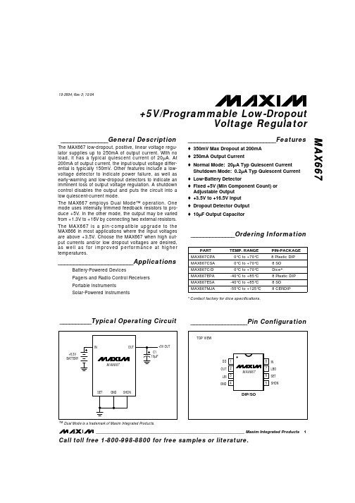
_______________General Description The MAX667 low-dropout, positive, linear voltage regu-lator supplies up to 250mA of output current. With no load, it has a typical quiescent current of 20µA. At 200mA of output current, the input/output voltage differ-ential is typically 150mV. Other features include a low-voltage detector to indicate power failure, as well as early-warning and low-dropout detectors to indicate an imminent loss of output voltage regulation. A shutdowncontrol disables the output and puts the circuit into a low quiescent-current mode.The MAX667 employs Dual Mode™ operation. Onemode uses internally trimmed feedback resistors to pro-duce +5V. In the other mode, the output may be varied from +1.3V to +16V by connecting two external resistors.The MAX667 is a pin-compatible upgrade to theMAX666 in most applications where the input voltagesare above +3.5V. Choose the MAX667 when high out-put currents and/or low dropout voltages are desired,as well as for improved performance at highertemperatures.________________________Applications Battery-Powered Devices Pagers and Radio Control Receivers Portable Instruments Solar-Powered Instruments ____________________________Features o 350mV Max Dropout at 200mAo 250mA Output Currento Normal Mode: 20µA Typ Quiescent Current Shutdown Mode: 0.2µA Typ Quiescent Current o Low-Battery Detectoro Fixed +5V (Min Component Count) orAdjustable Outputo +3.5V to +16.5V Inputo Dropout Detector Outputo 10µF Output Capacitor ______________Ordering Information MAX667+5V/Programmable Low-Dropout Voltage Regulator ________________________________________________________________Maxim Integrated Products 1__________________Pin Configuration __________Typical Operating Circuit Call toll free 1-800-998-8800 for free samples or literature.19-3894; Rev 3; 10/94* Contact factory for dice specifications.TM Dual Mode is a trademark of Maxim Integrated Products.M A X 667+5V/Programmable Low-Dropout Voltage Regulator2_______________________________________________________________________________________ABSOLUTE MAXIMUM RATINGS Stresses beyond those listed under “Absolute Maximum Ratings” may cause permanent damage to the device. These are stress ratings only, and functional operation of the device at these or any other conditions beyond those indicated in the operational sections of the specifications is not implied. Exposure to absolute maximum rating conditions for extended periods may affect device reliability.Input Supply Voltage ...........................................................+18V Output Short Circuited to Ground.........................................1sec LBO Output Sink Current....................................................50mA LBO Output Voltage...............................................GND to V OUT SHDN Input Voltage....................................-0.3V to (V IN + 0.3V)Input Voltages LBI, SET................................-0.3V to (V IN - 1.0V)Continuous Power DissipationPlastic DIP (derate 9.09mW/°C above +70°C)............727mW SO (derate 5.88mW/°C above +70°C).........................471mW CERDIP (derate 8.00mW/°C above +70°C).................640mW Operating Temperature Ranges MAX667C_A........................................................0°C to +70°C MAX667E_A.....................................................-40°C to +85°C MAX667MJA..................................................-55°C to +125°C Storage Temperature Range.............................-65°C to +160°C Lead Temperature (soldering, 10sec).............................+300°C Note 1:Dropout Voltage is V IN -V OUT when V OUT falls to 0.1V below its value at V IN = V OUT + 2V.Note 2:Short-Circuit Current is pulse tested to maintain junction temperature. Short-circuit duration is limited by package dissipation.ELECTRICAL CHARACTERISTICS(GND = 0V, V = +9V, V = +5V, C1 = 10µF, unless otherwise noted.)MAX667+5V/Programmable Low-Dropout Voltage Regulator3100011101001000DROPOUT VOLTAGE vs. LOAD CURRENT 10100M A X 667-F g T O C 1LOAD CURRENT (mA)D R O P O U TV O LT A G E (m V )QUIESCENT CURRENT vs. LOAD CURRENT Q UIE S C EN T C U R R E N T(µA )10100100010,000100,0000.010.11101001000LOAD CURRENT (mA)1000105015025010100100200DD OUTPUT CURRENTvs. INPUT-OUTPUT DIFFERENCE DDO U TPUTC UR REN T(µA )INPUT-OUTPUT DIFFERENCE (mV)__________________________________________Typical Operating Characteristics _____________________Pin Description _______________Detailed DescriptionFigure 1 shows a micropower bandgap reference, anerror amplifier, a PNP pass transistor, and two com-parators as the main elements of the MAX667. One comparator, C1, selects the fixed 5V or adjustable operation with an external voltage divider. The othercomparator, C2, is a low-battery detector.The bandgap reference, which is trimmed to 1.22V,connects internally to one input of the error amplifier,A1. The feedback signal from the regulator output sup-plies the other input of A1 from either an on-chip volt-age divider or two external resistors. When SET is grounded, the internal divider provides the error ampli-fier feedback signal for a fixed 5V output. When SET is more than 50mV above ground, the error amplifier’sinput switches directly to SET while an external resistor divider from OUT determines the output voltage.A second comparator, C2, compares the LBI input to the internal reference voltage. LBO is an open-drain FET connected to GND. The low-battery threshold canalso be set with a voltage divider at LBI. In addition, the MAX667 has a shutdown input (SHDN) that disables the load and the device while reducing quiescent cur-rent when it is pulled high.+5V OutputFigure 2 shows the connection for a fixed 5V output.The SET input is grounded, and no external resistors are required. Figure 3 shows adjustable output opera-tion. R1 and R2 set the output voltage. SHDN should be grounded if not used.(T A = +25°C, unless otherwise noted.)M A X 667+5V/Programmable Low-Dropout Voltage Regulator4_______________________________________________________________________________________Figure 2. Fixed +5V RegulatorFigure 3. Adjustable Output and Low-Battery DetectorOutput-Voltage Selection If SET is connected to a resistive voltage divider (Figure 3), the output voltage is set by the equation:V OUT = V SET x (R1 + R2) / R1,where V SET = 1.22V To simplify resistor selection:R2 = R1 x (V OUT / V SET - 1)Since the input bias current at SET has a maximum value of 10nA, relatively large values can be used for R1 and R2 with no loss of accuracy. 1M Ωis a typical value for R1. The V SET tolerance is less than ±25mV.This allows the output to be preset without trim pots,using only fixed resistors in most cases. However,when resistor values greater than 1M Ωare used, pay special attention to printed circuit board leakage that can introduce error at the SET input.Shutdown (Standby) Mode SHDN puts the device into standby mode to conserve power. When this pin is held low, the IC operates nor-mally. If it is driven above 1.5V, the chip shuts down.Quiescent current of the MAX667 is then reduced toless than 1µA, and OUT turns off. Note that the voltage for SHDN must never be more than 0.3V higher than V IN .Low-Battery Function The MAX667 contains circuitry for low-battery detec-tion. If the voltage at LBI falls below the regulator’s internal reference (1.22V), LBO, an open-drain output,sinks current to GND. The threshold can be set to anylevel above the reference voltage by connecting aresistive divider to LBI based on the equation:R3 = R4 x (V BATT / V LBI - 1)where V BATT is the desired threshold of the low-batterydetector, and R3 and R4 are the LBI input divider resistors.Since LBI input current is no more than 10nA, high val-ues for R3 and R4 minimize loading. If V OUT is 5V, a5.5V low-battery threshold can be set using 8.2M Ωfor R3 and 2.4M Ωfor R4. When resistor values greater than 1M Ωare used, pay special attention to PC board leakage that can introduce error at the LBI input.When the voltage at LBI is below the internal threshold,LBO sinks current to GND. A pull-up resistor of 10k Ωor more connected to OUT can be used with this pin when driving CMOS circuits. Any pull-up resistor connectedto LBO should not be returned to a voltage sourcegreater than VOUT . When LBI is above the threshold or the MAX667 is in SHDN mode, the LBO output is off.Dropout DetectorThe minimum input-output differential, or dropout volt-age, determines the regulator’s lowest usable inputvoltage. In battery-operated systems, this determines the useful end-of-life battery voltage. The MAX667 fea-tures very low dropout voltage (see ElectricalCharacteristics ). In addition, the MAX667 has a dropoutdetector output, DD, that changes as the dropout volt-age approaches its limit. DD is an open collector of a PNP transistor. The dropout voltage and the dropout detector both depend on the output current and tem-perature. When the input voltage is more than 300mV above the output voltage, the dropout detector will not conduct. As the differential decreases below 300mV,the DD source current increases abruptly. This current signals a warning that regulation is about to be lost.Connecting a resistor (typically 100k Ω) from DD toground develops a voltage that can be monitored by analog circuits or changed to digital levels by a com-parator. LBI may be used for this purpose.__________Applications Information Output Capacitor As with all PNP output regulators, an output capacitor (C1, Figure 2) is required to maintain stability. 10µF isrecommended. To ensure stability, the output-capacitorESR must be sufficiently high. Figure 4 shows the mini-mum required output-capacitor ESR for a given temper-ature. Alternatively, a resistor may be added in series with the output capacitor (Figure 5); the sum of the out-MAX667+5V/Programmable Low-Dropout Voltage Regulator_______________________________________________________________________________________5Figure 4. Minimum Required Output-Capacitor ESR vs.TemperatureM A X 667minimum, meet the requirements shown in Figure 4.An upper limit to the output-capacitor ESR is importantonly if step changes to the load are anticipated. HigherESR results in higher-amplitude output-voltage tran-sients when the output current is varied. A SanyoOS-CON capacitor, whose ESR is nearly flat over tem-perature (and is low to begin with), in series with theappropriate resistor ensures the best load-transientperformance. A less expensive alternative is to use atantalum capacitor in series with the resistor.In most cases, inexpensive aluminum-electrolytic capacitors work well with the MAX667 over their entire temperature range, having sufficient ESR to ensure sta-bility without the need for a series resistor. The ESR of aluminium electrolytics rises, often dramatically, as temperature decreases. For surface-mount applica-tions, certain tantalum capacitors have sufficient ESR;an example is the TAJB106K016 chip capacitor made by AVX (phone: (803) 448-9411, fax: (803) 448-1943). Battery DrainThe MAX667 uses a PNP output transistor. When theinput voltage falls below the desired output voltage, the+5V/Programmable Low-Dropout Voltage Regulator6_______________________________________________________________________________________Figure 7. Connection for Minimum Quiescent Current NearDropoutFigure 8. Quiescent Current Below Dropout for Circuit ofFigure 2PNP transistor is turned on fully as regulation is lost.Even with a load current of a few microamperes, thebase current will be driven above 5mA. Figure 8 showshow this base current may be significant.Consequently, a mostly discharged battery can be fur-ther discharged at end-of-life.Figure 6 shows how this condition can be modified by connecting DD to SHDN with a 47k Ωresistor, R1, par-alleled with a 0.1µF capacitor to GND. This modifica-tion reduces the no-load quiescent current to approximately 160µA when dropout is reached (Figure9), but increases the dropout voltage by about 0.1V.The output voltage drops to approximately 3V once DD begins to activate SHDN, but it does not fall to zero because SHDN is only partially activated.A second alternate connection (Figure 7) further reduces quiescent current near the dropout voltage,compared to the circuit in Figure 6. The output must be set with external resistors (R1, R2), so DD lowers theoutput voltage as the input voltage falls by sourcing current into SET via R3. Quiescent current remains low for inputs down to 3.5V, and peaks before falling to 0at low input voltages. Although the current peak is higher than with the connection in Figure 6, this may be more useful because the quiescent current peaks at an input voltage well below the useful range of most batteries (Figure 9). Also, as IN falls below 5V, OUT tracks IN minus the dropout voltage. This connection still allows separate use of the SHDN input.Power Dissipation The MAX667 can regulate currents as high as 250mA and withstand input-output differential voltages as highas 15.2V, but not simultaneously. The maximum power dissipation is dependent on the package and the tem-perature (see Absolute Maximum Ratings ). Figure 10shows the maximum output current at various input-output differential voltages for the plastic DIP and SO packages. The MAX667 can withstand short-circuit loads up to 1 second.Operation from AC Sources The MAX667 is a micropower CMOS regulator intend-ed principally for battery operation. When operatingfrom AC sources, consider power-supply ripple rejec-tion. The MAX667’s error amplifier produces very low gain bandwidth, and the input power-supply rejectionMAX667+5V/Programmable Low-Dropout _______________________________________________________________________________________7Voltage RegulatorFigure 9. Quiescent Current Below Dropout with Connections of Figures 6 and 7Figure 11. Output Response to +4V/100µs Input Step +10V+6VINPUT+2V/div+5V OUTPUT+0.2V/divMaxim cannot assume responsibility for use of any circuitry other than circuitry entirely embodied in a Maxim product. No circuit patent licenses are implied. Maxim reserves the right to change the circuitry and specifications without notice at any time.8___________________Maxim Integrated Products, 120 San Gabriel Drive, Sunnyvale, CA 94086 (408) 737-7600©1994 Maxim Integrated Products Printed USA is a registered trademark of Maxim Integrated Products.M A X 667+5V/Programmable Low-Dropout Voltage Regulator ratio (PSRR) is therefore not specified. Since the outputmust be connected to a 10µF or larger filter capacitor,the capacitor characteristics dominate the PSRR. Largevalues of input and output capacitors reduce the ripple.In addition, both DD and LBI/LBO can trigger on thelowest DC component of the ripple, particularly at highload currents. In the case of the low-battery detector,the ripple can be effectively filtered out by placing a capacitor to ground in parallel with the LBI input pin.The high resistance values that can be used for thevoltage divider allow relatively small capacitance val-ues to form an effective lowpass filter at 120Hz. Whenpower is first applied, however, this filter tends to holdLBO low longer than normal.Transient ConsiderationsThe low operating current and gain-bandwidth productof the internal reference and amplifier result in limitedrejection of fast-step input changes. Negative-goingsteps, which occur in under 100µs, may turn off the out-put for several milliseconds. An input filter (nominally10µF) is recommended if input changes greater than1V and faster than 100µs (other than turn-on or turn-off)are anticipated. Figure 12 shows the output responseto a 10mA/100mA instantaneous load step. The rela-tionship between output-capacitor ESR and load-tran-sient response is explained in the Output Capacitorsection.___________________Chip Topography OUTPUTCURRENT+5V OUTPUT 0.1V/div 100mA10mA200µs/divFigure 12. Output Response to 10mA/100mA Load Step with10µF Output Capacitor (1.5Ω ESR)LBO SETLBI OUTDD INSHDN GND 0.107" (2.71mm)0.070" (1.78mm)TRANSISTOR COUNT: 65SUBSTRATE MUST BE LEFT UNCONNECTED。
JMF612
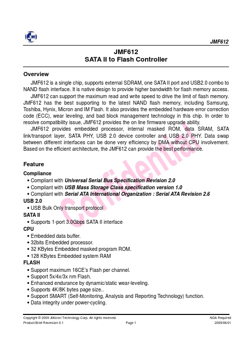
JMF612JMF612 SATA II to Flash ControllerOverviewJMF612 is a single chip, supports external SDRAM, one SATA II port and USB2.0 combo to NAND flash interface. It is native design to provide higher bandwidth for flash memory access. JMF612 can support the maximum read and write speed to drive the limit of flash memory. JMF612 has the best supporting to the latest NAND flash memory, including Samsung, Toshiba, Hynix, Micron and IM Flash. It also provides the embedded hardware error correction code (ECC), wear leveling, and bad block management technology in this chip. In order to resolve compatibility issue, JMF612 provides the on line firmware upgrade ability. JMF612 provides embedded processor, internal masked ROM, data SRAM, SATA link/transport layer, SATA PHY, USB 2.0 device controller and USB 2.0 PHY. Data swap between different interfaces can be done very efficiency by DMA without CPU involvement. Based on the efficient architecture, the JMF612 can provide the best performance.FeatureCompliance • Compliant with Universal Serial Bus Specification Revision 2.0 • Compliant with USB Mass Storage Class specification version 1.0 • Compliant with Serial ATA International Organization : Serial ATA Revision 2.6 USB 2.0 • USB Bulk Only transport protocol SATA II • Supports 1-port 3.0Gbps SATA II interface CPU • Embedded data buffer. • 32bits Embedded processor. • 32 KBytes Embedded masked program ROM. • 128 KBytes Embedded system RAM FLASH • Support maximum 16CE’s Flash per channel. • Support 5x/4x/3x nm Flash. • Enhanced endurance by dynamic/static wear-leveling. • Supports 4K/8K bytes page size.. • Support SMART (Self-Monitoring, Analysis and Reporting Technology) function. • Data integrity under power-cycling.Copyright © 2009 JMicron Technology Corp. All rights reserved. Product Brief Reversion 0.1 Page 1 NDA Required 2009/08/01JMF612 • Supports online SATA/USB firmware update. • Supports 8 bits Flash interface. • Supports BCH 16/24 bits ECC. • 250/200 MBytes/sec Sequential read/write rates (MLC). • 6000/10000 IOPS 4K random read/write rates (MLC). SDRAM • Support DDR/DDR2 • Support 128Mbits to 2Gbits SYSTEM • Integrated 1-port USB2.0, 1-port SATA II and 8-channel Flash controller • LED indicator for USB2.0 or SATA read/write access • LED indicator for USB2.0 or SATA PHY link up • Provides 15 GPIO pins for customer • Provides UART and JTAG for S/W debugging • Available in 281-pin BGA(12 mm * 12 mm) packageFunctional Block DiagramContact Information• Sales : sales@ • Tech. Support : fae@Copyright © 2009 JMicron Technology Corp. All rights reserved. Product Brief Reversion 0.1 Page 2NDA Required 2009/08/01。
EFM32 中文

I C 接口,带SMBus 支持 • Stop模式地址识别 • 超低功耗高精度模拟外设 • 12-位 1 M采样/秒 ADC转换器 单端或差分模式
片上温度传感器
独有转换Conversion tailgating for predictable latency 技术 • 12-位 500 k采样/秒 DAC转换器 • 2 单端通道/1 差分通道 • 2× 模拟比较器 可编程速率/电流 最大8通道容性输入 供电电压比较器
2 系统概述 ................................................................................................................................................................7 2.1 系统简介 ..........................................................................................................................................................7 2.1.1 ARM Cortex ‐ M3 内核 ..............................................................................................................................7 2.1.2 调试接口(DBG).................................................................................
MEMORY存储芯片MT8KTF51264HZ-1G9P1中文规格书
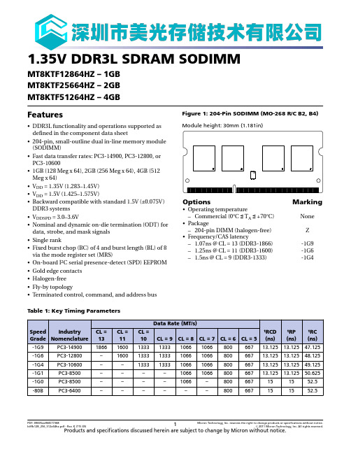
-80B
PC3-6400
CL = 13 1866 – – – – –
CL = 11 1600 1600 – – – –
Data Rate (MT/s)
CL = 10 CL = 9 CL = 8 CL = 7
1333 1333 1066 1066
1333 1333 1066 1066
1333 1333 1066 1066
Parity input: Parity bit for Ax, RAS#, CAS#, and WE#.
Command iong with S#) define the command being entered.
Reset: RESET# is an active LOW asychronous input that is connected to each DRAM and the registering clock driver. After RESET# goes HIGH, the DRAM must be reinitialized as though a normal power-up was executed.
Table 7: Pin Descriptions
Symbol Ax
BAx
富豪DDRⅡ 667MHz内存评测

频 能力相 当不错 , 适合普 通消 费者 以及入 门级 发烧
友 使用 。
DI No 1 .0 6 8 Y .22 0 3
维普资讯
谴 性 | 消 让D Y改 生 理 费 导 变 堰 l
报道行业动态 品评存储 酷品 折 存储 技术
时间消沉之后有又开始重新走回到大众消费者面前,本次 评测 ,我们带给大家的是富豪 D R I6 z D I 6 MH 的内存评测。 7
的产 品 , 但是 产 品的超频 性能 不佳 那 么我们 这次
测 试 的 DDR I6 7 I 6 MHz的产 品超 频能 力如 何 昵 7
我 仇使 用了最新 的 E 7 0 60 措配 9 5 7 X芯 片组进 行测
内存 的 S D参数 P
测试 点评
我们认 为 , 这款 富 豪D R I 7 H 的 内存 , D I 6 z 6M 超
试 .内存可 以运ຫໍສະໝຸດ 在 80 z 0 MH ,并且 完成 测试 在
电压增 加到 22 .V的情 况下 , 这款 内 存最高 可 以运行 至 80 5 MHz以上 ,不 过 可惜 无法 完成 测试 。
我 们 测 试 的 内 存 使 用 了 6层 P ,搭 配 了 B C
F BGA封 装 的内存颗 粒 。由于厂 家进行 了打磨 我 们 无法具体 辨别 产品使 用 的颗粒情 况 。在 测试 这款 产 品之前 ,我 们 曾测试 过 富 豪的 DDR I8 0 I 0 MHz
忆捷SSD固态硬盘

2014 EAGET SSD TRAINING
S600基本参数
类别 支持系统
质保时间
微软系统 Windows8 Windows7
3年保固
Windows2000(SP4) WindowsXP(SP3) WindowsVista(SP1)
苹果系统
开放系统
Mac OSX V.10.3.x+ Linux v.2.6.X+
SSD基本要素
Performance
读写速度 (Random R/W, 4K IOPS)
常用测试软件有: IO Meter Crystal Disk Mark(CMD) ATTO Bench Mark AS SSD Bench Mark
TMS320C6678DSP+XilinxKintex-7FPGA核心板硬件参数资源说明分享
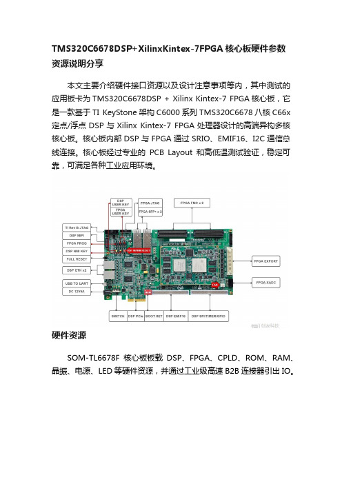
TMS320C6678DSP+XilinxKintex-7FPGA核心板硬件参数资源说明分享本文主要介绍硬件接口资源以及设计注意事项等内,其中测试的应用板卡为TMS320C6678DSP + Xilinx Kintex-7 FPGA核心板,它是一款基于TI KeyStone架构C6000系列TMS320C6678八核C66x 定点/浮点DSP与Xilinx Kintex-7 FPGA处理器设计的高端异构多核核心板。
核心板内部DSP与FPGA通过SRIO、EMIF16、I2C通信总线连接。
核心板经过专业的PCB Layout和高低温测试验证,稳定可靠,可满足各种工业应用环境。
硬件资源SOM-TL6678F核心板板载DSP、FPGA、CPLD、ROM、RAM、晶振、电源、LED等硬件资源,并通过工业级高速B2B连接器引出IO。
图 1 核心板硬件框图图 2图 3DSP核心板DSP型号兼容TMS320C6678ACYPA25(1.25GHz)、TMS320C6678ACYPA(1GHz),FCBGA(841)封装,工作温度为-40°C~100°C,引脚数量为841个,尺寸为24mm*24mm。
TI TMS320C6678处理器架构如下:图 4 TMS320C6678处理器功能框图FPGA核心板FPGA型号为XC7K325T-2FFG676I,FFG676封装,工作温度范围为-40°C~100°C,引脚数量为676个,尺寸为27mm*27mm。
Kintex-7系列FPGA特性如下所示:图 5 Kintex-7系列FPGA特性ROMNAND FLASH核心板DSP通过EMIF16总线连接工业级NAND FLASH,采用8bit数据线,型号为S34MS01G2,容量为128MByte。
SPI NOR FLASH核心板DSP通过SPI总线连接工业级SPI NOR FLASH,型号兼容GigaDevice公司的GD25WQ128E和Micron公司的MT25QU128ABA,容量为128Mbit。
XILINX推出业界第一款667 Mbps DDR2 SDRAM接口解决方案
XILINX推出业界第一款667 Mbps DDR2 SDRAM接口解
决方案
佚名
【期刊名称】《《电子与电脑》》
【年(卷),期】2006(000)004
【摘要】赛灵思公司(NASDAQ XLNX)宣布,即日起推出基于Virtex-4 FPGA 的667 Mbps DOR2参考设计,该参考设计提供了FPGA业界带宽最高,最可靠的内存接口解决方案。
赛灵思667 DDR2-SDRAM接口采用了创新的Virtex-4 ChipSync技术,这是一种运行时校准电路,可以极大地提高设计余量和整体系统可靠性,同时缩短设计周期。
【总页数】1页(P68)
【正文语种】中文
【中图分类】TP334.7
【相关文献】
1.Xilinx推出业界首款“软”定义网络(SDNet)解决方案 [J], Xilinx
2.Xilinx和Pico Computing联手推出业界首款15Gb/s HMC接口 [J], 消息赛灵思公司
3.XILINX推出业界首个可编程EXPRESSCARD解决方案 [J],
4.Xilinx FPGA处理器解决方案为嵌入式系统设计人员提供强大的性能优势独立测试结果再次肯定了Xilinx业界最全面的基于FPGA的32位嵌入式处理解决方案的领先地位 [J],
5.XILINX面向快速增长的多功能智能手机市场推出业界第一款可编程演示平台 [J],
因版权原因,仅展示原文概要,查看原文内容请购买。
创见DDR2 533/667内存
创见DDR2 533/667内存
雷军
【期刊名称】《《微型计算机》》
【年(卷),期】2006(000)001
【摘要】作为全球第三大特殊型内存记忆体制造商,创见一直是台湾省内存市场的第一品牌,但是由于之前一直致力于闪存领域而且主要面向企业级用户。
【总页数】1页(P11)
【作者】雷军
【作者单位】
【正文语种】中文
【中图分类】TP333.1
【相关文献】
1.迈进DDR2时代——金士刚DDR2 533内存测试 [J],
2.再战DDR2创见DDR2 533/667内存 [J], 雷军
3.330元也能买DDR2 667——富豪DDR2 667 512MB内存 [J],
4.DDR2普及时代来临南亚易胜DDR2 533内存 [J], 刘宗宇
5.走近新一代主流内存 DDR2 533/667内存横向评测 [J],
因版权原因,仅展示原文概要,查看原文内容请购买。
飞速存取——Infineon DDR2-667品析

飞速存取——Infineon DDR2-667品析
Mindon
【期刊名称】《电脑自做》
【年(卷),期】2005(000)003
【摘要】尽管DDR2内存市场仍处于冰冻状态,但内存厂商却没有延缓推陈出新的步伐。
不久前国际内存巨头Infineon(英飞凌)送来了Galaxy星河系列内存的新品DDR2-667。
【总页数】1页(P64)
【作者】Mindon
【作者单位】无
【正文语种】中文
【中图分类】TP311.13
【相关文献】
1.DOAJ收录我国开放存取期刊的统计与分析——兼谈如何提高我国开放存取期刊的发展水平 [J], 赵兵;郭才正;钱景
2.记飞速崛起的东营英华园学校——记飞速崛起的东营英华园学校 [J], 蒋建敏
3.WINTEC美商威特AMPX DDR2-667 1GB内存 [J], 胡纲
4.南亚原厂颗粒信心保证南亚易胜DDR2-667/1G内存 [J],
5.如何在品析“炼字炼句”中获得情感体验——以《十五从军征》品析为例 [J], 周雪扬
因版权原因,仅展示原文概要,查看原文内容请购买。
TMS320C6678FAQ
TMS320C6678FAQ目录1. 提供的技术参考文档有哪些 (1)2. 你们的硬件系统可以接入哪些接口哪些厂家的相机 (1)3. 嵌入式DSP图像处理系统有什么优点 (2)4. 你们设计的板卡与TI提供的开发板有何区别? (3)5. 与工控机比较,TMS320C6678的运算性能如何 (7)6. 没有相机厂家提供的SDK,DSP如何做到Gige相机的接入 (7)7. 你们是如何利用Lwip实现60MB/s以上的网络速率的。
(9)8. TMS320C6678的软件开发难度大吗 (10)9. 在编程时如何实现多核调度和并行计算 (12)10. 你们板子可扩展哪些底板和接口 (13)11. 你们的产品是如何销售定价的 (13)1.提供的技术参考文档有哪些面向多相机接入的TMS320C6678图像处理系统产品手册面向多相机接入的TMS320C6678图像处理系统快速使用说明面向多相机接入的TMS320C6678图像处理系统硬件设计说明(中文版)面向多相机接入的TMS320C6678图像处理系统硬件设计说明(英文版)面向多相机接入的TMS320C6678图像处理系统软件开发说明面向多相机接入的TMS320C6678图像处理系统算法开发例程面向多相机接入的TMS320C6678图像处理系统视频编解码实现2.你们的硬件系统可以接入哪些接口哪些厂家的相机支持Basler/Dalsa等国际主流CameraLink、Gige相机的全速接入,提供DSP CCS环境下的相机驱动软件,具体支持的信号如下(不断更新中):(1)Scout系列千兆网(GigE Vision)面阵摄像头Scout系列分辨率感光芯片帧速率(fps) 功率重量scA640-70gm/gc 659 x 494 Sony ICX424 70 ~3 W ~160 g scA640-74gm/gc 659 x 494 Sony ICX414 79 ~3 W ~160 g scA640-120gm/gc 659 x 494 Sony ICX618 122 ~3.5 W ~160 g scA750-60gm/gc 752 x 480 Aptina MT9V022 64 ~2.5 W ~160 g scA780-54gm/gc 782 x 582 Sony ICX415 55 ~3 W ~160 g scA1000-30gm/gc 1034 x 779 Sony ICX204 31 ~3 W ~160 g scA1300-32gm/gc 1296 x 966 Sony ICX445 32 ~3.5 W ~160 g scA1390-17gm/gc 1392x1040 Sony ICX267 17 ~3.5 W ~160 g scA1400-17gm/gc 1392x1040 Sony ICX285 17 ~3.5 W ~170 g scA1400-30gm/gc 1392x1040 Sony ICX285 30 ~4.2 W ~170 g scA1600-14gm/gc 1628x1236 Sony ICX274 14 ~3.5 W ~160 g scA1600-28gm/gc 1628x1236 Sony ICX274 28 ~4.3 W ~160 g (2)Ace系列千兆网(GigE Vision)面阵摄像头规格Ace系列分辨率感光芯片帧速率(fps) 功率重量acA640-90gm/gc 659x494 Sony ICX424 90 ~3.1W ~90g acA640-120gm/gc 659x494 Sony ICX618 120 ~2.3W ~90g acA645-100gm/gc 659x494 Sony ICX414 100 ~3.6W ~90g acA750-30gm/gc 752x580 Sony ICX409 30 ~2.5W ~90g acA780-75gm/gc 782x582 Sony ICX415 60 ~3.6W ~90g信息识别与系统控制研究中心1acA1280-60gm/gc 1280x1024 EV76C560 60 ~2.5W ~90g acA1300-22gm/gc 1296x966 Sony ICX445 22 ~2.2W ~90g acA1300-30gm/gc 1296x966 Sony ICX445 30 <3.0W ~90g acA1300-60gm/gc 1280x1024 EV76C560 60 <3.0W ~90g acA1300-60gm NIR1280x1024 EV76C661 60 <3.0W ~90g acA1600-20gm/gc 1628x1236 Sony ICX274 20 ~3.4W ~90g acA1600-60gm/gc 1600x1200 EV76C57060 <3.0W ~90g acA1920-25gm/gc 1920x1088 Aptina MT9P031 25 ~2.2W ~90g acA2000-50gm/gc 2048x1088 CMOSIS CMV2000 50 ~3.4W ~90g acA2000-50gm/gc NIR2048x1088 CMOSIS CMV2000 NIR 增强型50 ~3.4W ~90g acA2040-25gm/gc 2048x2048 CMOSIS CMV4000 25 ~3.4W ~90g acA2040-25gm/gc NIR2048x2048 CMOSIS CMV4000 NIR 增强型25 ~3.4W ~90g acA2500-14gm/gc2592x1944Aptina MT9P14~2.5W~90g(3)Pilot 系列千兆网(GigE Vision)面阵摄像头规格Scout 系列分辨率感光芯片帧速率(fps)功率重量piA640-210gm/gc 648 x 488 Kodak KAI-0340 210 ~5.5W 220gpiA1000-48gm/gc 1004 x 1004 Kodak KAI-1020 48 piA1000-60gm/gc 1004 x 1004 Kodak KAI-1020 60 piA1600-35gm/gc 1608 x 1208 Kodak KAI-2020 35 piA1900-32gm/gc 1928 x 1084 Kodak KAI-2093 32 piA2400-17gm/gc2456 x 2058Sony ICX625173. 嵌入式DSP 图像处理系统有什么优点(1)极快的运算速度,确保图像处理算法的实时性DSP 处理器从TMS320DM642开始进入图像处理领域,随后的Davinci 处理器TMS320DM6467在智能交通(卡口、车牌识别)、安防(运动目标检测跟踪、周界防范)等领域得到的大规模应用。
- 1、下载文档前请自行甄别文档内容的完整性,平台不提供额外的编辑、内容补充、找答案等附加服务。
- 2、"仅部分预览"的文档,不可在线预览部分如存在完整性等问题,可反馈申请退款(可完整预览的文档不适用该条件!)。
- 3、如文档侵犯您的权益,请联系客服反馈,我们会尽快为您处理(人工客服工作时间:9:00-18:30)。
JMF667/667H NAND Flash and DDR3 Support ListFor F/W SVN308aDocument No.: 667-00001 / Revision: 1.1 / Release Date: 2014-02-13JMicron Technology Corporation1F, No. 13, Innovation Road 1, Science-Based Industrial Park,Hsinchu, Taiwan 300, R.O.C.Tel: 886-3-5797389Fax: 886-3-5799566Website: Certificate No.: FM 84262JMF667/667HNAND Flash and DDR3 support listRevision 1.1 iDocument No.: 667-00001The information contained in this document is the exclusive property of JMicron Technology Corporation and shall not be used, collected, reproduced, distributed and/or disclosed in whole or in part without prior written permission of JMicron Technology Corporation. Hard copies or electronic files downloaded from JMicron Document Control System are for reference only. Please enter JMicron Document Control System to access updated documents or download updated documents from the authorized FTP site.1F, No.13, Innovation Road 1, Science-Based Industrial Park, Hsinchu, Taiwan 300, R.O.C. Tel: 886-3-5797389 Fax: 886-3-5799566JMF667/667HNAND Flash and DDR3 support listRevision 1.1 iiDocument No.: 667-00001The information contained in this document is the exclusive property of JMicron Technology Corporation and shall not be used, collected, reproduced, distributed and/or disclosed in whole or in part without prior written permission of JMicron Technology Corporation. Hard copies or electronic files downloaded from JMicron Document Control System are for reference only. Please enter JMicron Document Control System to access updated documents or download updated documents from the authorized FTP site.Revision HistoryJMF667/667HNAND Flash and DDR3 support listRevision 1.1 iiiDocument No.: 667-00001The information contained in this document is the exclusive property of JMicron Technology Corporation and shall not be used, collected, reproduced, distributed and/or disclosed in whole or in part without prior written permission of JMicron Technology Corporation. Hard copies or electronic files downloaded from JMicron Document Control System are for reference only. Please enter JMicron Document Control System to access updated documents or download updated documents from the authorized FTP site.Table of ContentsRevision History...........................................................................................................................................................ii 1 1 2 7 8JMF667/667HNAND Flash and DDR3 support listRevision 1.1 1Document No.: 667-00001The information contained in this document is the exclusive property of JMicron Technology Corporation and shall not be used, collected, reproduced, distributed and/or disclosed in whole or in part without prior written permission of JMicron Technology Corporation. Hard copies or electronic files downloaded from JMicron Document Control System are for reference only. Please enter JMicron Document Control System to access updated documents or download updated documents from the authorized FTP site.1 I n t r o d u c t i o nJMF667 is a single chip, supports external DDR3 DRAM, SATA III to NAND flash interface. It is native design to provide higher bandwidth for flash memory access.JMF667 can support the maximum read and write speed to drive the limit of flash memory. JMF667 has the Supports one module DDR3. Support up-to 2Gbits.JMF667/667HNAND Flash and DDR3 support listRevision 1.1 2Document No.: 667-00001The information contained in this document is the exclusive property of JMicron Technology Corporation and shall not be used, collected, reproduced, distributed and/or disclosed in whole or in part without prior written permission of JMicron Technology Corporation. Hard copies or electronic files downloaded from JMicron Document Control System are for reference only. Please enter JMicron Document Control System to access updated documents or download updated documents from the authorized FTP site.3 S u p p o r t L i s t3.1 NAND Flash support listJMF667/667HNAND Flash and DDR3 support listRevision 1.1 3Document No.: 667-00001The information contained in this document is the exclusive property of JMicron Technology Corporation and shall not be used, collected, reproduced, distributed and/or disclosed in whole or in part without prior written permission of JMicron Technology Corporation. Hard copies or electronic files downloaded from JMicron Document Control System are for reference only. Please enter JMicron Document Control System to access updated documents or download updated documents from the authorized FTP site.*16K\19nm C(B)\Toggle : TSOP is Legacy to Toggle mode ;BGA is Toggle mode.▲: Only for testJMF667/667HNAND Flash and DDR3 support list ArrayRevision 1.1 4 Document No.: 667-00001The information contained in this document is the exclusive property of JMicron Technology Corporation and shall not be used, collected,reproduced, distributed and/or disclosed in whole or in part without prior written permission of JMicron Technology Corporation. Hard copiesor electronic files downloaded from JMicron Document Control System are for reference only. Please enter JMicron Document ControlSystem to access updated documents or download updated documents from the authorized FTP site.JMF667/667HNAND Flash and DDR3 support list ArrayRevision 1.1 5 Document No.: 667-00001The information contained in this document is the exclusive property of JMicron Technology Corporation and shall not be used, collected,reproduced, distributed and/or disclosed in whole or in part without prior written permission of JMicron Technology Corporation. Hard copiesor electronic files downloaded from JMicron Document Control System are for reference only. Please enter JMicron Document ControlSystem to access updated documents or download updated documents from the authorized FTP site.JMF667/667HNAND Flash and DDR3 support list ArrayRevision 1.1 6 Document No.: 667-00001The information contained in this document is the exclusive property of JMicron Technology Corporation and shall not be used, collected,reproduced, distributed and/or disclosed in whole or in part without prior written permission of JMicron Technology Corporation. Hard copiesor electronic files downloaded from JMicron Document Control System are for reference only. Please enter JMicron Document ControlSystem to access updated documents or download updated documents from the authorized FTP site.JMF667/667H NAND Flash and DDR3 support list3.2 SDRAM support listDRAM Matrix with 667 & 667H SSD Density DDR I/F 32GB/24GB 64GB 128GB 256GB 64Mbx16bits=1Gbits,1pcs 64Mbx16bits=1Gbits,1pcs 64Mbx16bits=1Gbits,1pcs 128Mbx16bits=2Gbits,1pcs SD19B/TSB19B/L74A/L84A (8K page or one plane) DDR3 64Mbx16bits=1Gbits,1pcs 64Mbx16bits=1Gbits,1pcs 64Mbx16bits=1Gbits,1pcs 128Mbx16bits=2Gbits,1pcs SD19C/TSB19C/L85A (16K page)VendorDDRII SDRAM part numberNT5CB64M16DPDensity1G bits 2G bits 4G bits 1G bits 2G bits 4G bits 1G bits 2G bits 1G bits 1G bits 2G bitsOrganizationDrawing(mm) W9 9 10 9 9 10 7.5 9 9 9 9L13 13 13 14 14 14 13.5 13.5 13 13 13H1.2 1.2 1.2 1.1 1.1 1.1 1.2 1.2 1.2 1.2 1.2NANYANT5CB128M16HP NT5CB256M16BP MT41J64M16HAMicronMT41J128M16HA MT41J256M16REElpida Winbond ESMTEDJ1116DJBG EDJ2116DEBG W631GG6KB M15F1G1664A-8CBG M15F2G16128A-ADBGRevision 1.17Document No.: 667-00001The information contained in this document is the exclusive property of JMicron Technology Corporation and shall not be used, collected, reproduced, distributed and/or disclosed in whole or in part without prior written permission of JMicron Technology Corporation. Hard copies or electronic files downloaded from JMicron Document Control System are for reference only. Please enter JMicron Document Control System to access updated documents or download updated documents from the authorized FTP site.JMF667/667H NAND Flash and DDR3 support list3.3 SPI support listVendor ESMT P Flashpart numberF25L05PA –86SG2DDensity512Kbit 512Kbit 512KbitPackageTSSOP8 TSSOP8 TSSOP8Giga Device GD25Q512OIPPM25LD512C-DCERevision 1.18Document No.: 667-00001The information contained in this document is the exclusive property of JMicron Technology Corporation and shall not be used, collected, reproduced, distributed and/or disclosed in whole or in part without prior written permission of JMicron Technology Corporation. Hard copies or electronic files downloaded from JMicron Document Control System are for reference only. Please enter JMicron Document Control System to access updated documents or download updated documents from the authorized FTP site.JMF667/667H NAND Flash and DDR3 support list4 Controller to Flash CE pin definition F00 CH0CH0-BK0~3F01Data Bus [7:0]CH0-BK4~7F10 CH1CH1-BK0~3F11Data Bus [7:0]CH1-BK4~7F20 CH2CH2-BK0~3F21Data Bus [7:0]CH2-BK4~7F30 CH3CH3-BK0~3F31Data Bus [7:0]CH3-BK4~7Revision 1.19Document No.: 667-00001The information contained in this document is the exclusive property of JMicron Technology Corporation and shall not be used, collected, reproduced, distributed and/or disclosed in whole or in part without prior written permission of JMicron Technology Corporation. Hard copies or electronic files downloaded from JMicron Document Control System are for reference only. Please enter JMicron Document Control System to access updated documents or download updated documents from the authorized FTP site.Serial Link the World。
