汽车单级主减速器设计
汽车单级主减速器及差速器的结构设计与强度分析毕业论文
汽车单级主减速器及差速器的结构设计与强度分析毕业论文第一章绪论1.1 选题的背景与意义通过学校的实习我对汽车的构造及各总成的原理有了一定的了解,同时结合以前课堂学习的理论知识,对于进行汽车一些总成的设计有了一定的理论基础,现选择课题内容为对BJ2022汽车的使用性能的驱动桥(主减速器及差速器)进行设计。
通过本课题可以进一步加深对汽车构造、汽车设计及汽车各总成的工作原理,特别是本课题驱动桥中的主减速器及差速器与半轴的认识和了解;同时经过设计过程,了解学习一些现代汽车工业的新设计方法及新技术,对于即将从事汽车行业工作的我也是一种锻炼,为即将的工作做铺垫。
1.2 研究的基本内容1.2.1 主减速器的作用汽车传动系的总任务是传递发动机的动力,使之适应于汽车行驶的需要。
在一般汽车的机械式传动中,有了变速器还不能解决发动机特性与汽车行驶要求间的矛盾和结构布置上的问题。
而主减速器是在汽车传动系中起降低转速,增大转矩作用的主要部件。
当发动机纵置时还具有改变转矩旋转方向的作用。
它是依靠齿数少的齿轮带齿数多的齿轮来实现减速的,采用圆锥齿轮传动则可以改变转矩旋转方向。
汽车正常行驶时,发动机的转速通常比较高,如果将很高的转速只靠变速箱来降低下来,那么变速箱内齿轮副的传动比则需要很大,齿轮的半径也相应加大,也就是说变速箱的尺寸会加大。
另外,转速下降,扭矩必然增加,也加大了变速箱与变速箱后一级传动机构的传动负荷。
所以,在动力向左右驱动轮分流的差速器之前设置一个主减速器,可以使主减速器前面的传动部件,如变速箱、分动器、万向传动装置等传递的扭矩减小,同时也减小了变速箱的尺寸和质量,而且操控灵敏省力。
1.2.2 主减速器的工作原理从变速器或分动器经万向传动装置输入驱动桥的转矩首先传到主减速器,主减速器的一对齿轮增大转矩并相应降低转速,以及当发动机纵置时还具有改变转矩的旋转方向。
1.2.3 国内主减速器的状况现在国家大力发展高速公路网,环保、舒适、快捷成为汽车市场的主旋律。
[整理]主减速器的设计.
![[整理]主减速器的设计.](https://img.taocdn.com/s3/m/e59efb1e7fd5360cba1adbaa.png)
四、主减速器的设计(一) 主减速器概述地下自卸车广泛采用单级主传动,该主传动结构简单,质量小,成本低,使用简单,但主传动比0i 不能太大,一般0i ≤3.6~6.87。
因为进一步提高0i 将增大从动轮直径,从而减少离地间隙和使从动轮热处理复杂。
单级主减速器有螺旋锥齿轮、双曲面齿轮等两种形式。
螺旋锥齿轮传动,制造简单,工作中噪声大,对齿合精度很敏感,齿轮副锥顶稍有不吻合便使工作条件急剧变坏,伴随磨损、增大和噪声增大。
为保证齿轮副的正确齿合,必须将轴承顶紧,提高支承刚度,增大壳体刚度。
双曲面齿轮传动与螺旋锥齿轮传动不同之处,在于主、从动轴线不相交而有一偏移距E 。
由于存在偏移距,从而主动齿轮螺旋角1β与从动轮螺旋角2β不等,且21ββ>。
此时两齿轮切向力2F 与1F 之比,可 根据啮合面上法向力彼此相等的条件求出。
1212c o s /c o s/ββ=F F 设1r 与2r 分别为主、从动轮平均分度圆半径,双曲面的传动比os i 为 11221122c o s c o s ββr r r F r F i os ==对于螺旋锥齿轮传动,其传动比12/r r i d =,令12cos /cos ββ=K ,则K i r Kr i d os ==12/系数一般为1.25~1.5。
这说明当双曲面齿轮尺寸与螺旋锥齿轮尺寸相当时,双曲面传动有更大的传动比,当传动比一定,从动轮尺寸相同时,双曲面主动齿轮比螺旋锥齿轮有较大直径,较高的齿轮强度及较大的主动齿轮轴和轴承刚度,当传动比和主动齿轮尺寸一定时,双曲线从动锥齿轮直径比相应螺旋齿轮为小,因而离地间隙较大。
双曲面齿轮副在工作过程中,除了有沿齿高方向的侧向滑动之外,还有沿齿长方向的纵向滑动。
纵向滑动可改善齿轮的摩合过程,并使其工作安静平滑。
然而纵向滑动可使摩擦损失增加,降低传动效率,因而偏移距E 不应过大。
双曲面齿轮传动齿面间大的压力和大的摩擦功,可能导致油膜破坏和齿面烧结咬死。
单级主减速器的设计
1 主减速器的设计1.1 汽车的主要参数给定的参数如下: 驱动型式:4 2;装载质量/t:6;总质量/t :11;发动机最大功率/KW 及转速/r/min:114-2600; 发动机最大转矩/N m 及转速/r/min :539-1600; 主减速比i 0:4.44; 轮胎型号:8.25R20;变速器传动比抵挡/高档:6.3/1; 最高车速km/h :105。
满载轴荷分配:由于本设计采用的是4 2驱动、长头载货车,所以选定轴荷分配为前轴25%,后轴为75%[2]。
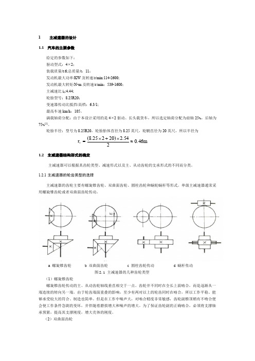
轮胎半径:型号为8.25R20,轮胎胎体直径为8.25英尺,轮辋直径为20英尺,所以半径为 =r r ()m 6.4024.5220225.8≈⨯+⨯1.2 主减速器结构形式的确定主减速器可以根据其齿轮类型、减速形式以及主、从动齿轮的支承形式的不同而分类。
1.2.1 主减速器的轮齿类型的选择主减速器的齿轮主要有螺旋锥齿轮、双曲面齿轮、圆柱齿轮和蜗轮蜗杆等形式。
单级主减速器通常采用螺旋锥齿轮或者双曲面齿轮传动。
a 螺旋锥齿轮b 双曲面齿轮c 圆柱齿轮传动d 蜗杆传动图2.1 主减速器的几种齿轮类型(1)螺旋锥齿轮螺旋锥齿轮传动的主、从动齿轮轴线垂直相交于一点。
齿轮并不同时在全长上面啮合,而是逐渐从一端连续的转向另一端。
由于轮齿端面重叠的影响,至少有两对以上的轮齿同时在啮合,所以工作平稳、能够承受较大的符合、制造也简单。
但是在工作中噪声大,对啮合精度非常敏感,齿轮副锥顶稍有不吻合便会使工作条件急剧的变坏,并伴随着磨损增大和噪声的增大。
为了保证齿轮副的正确啮合,必须将支撑轴承预紧,提高其支撑刚度,增大壳体的刚度。
(2)双曲面齿轮双曲面齿轮传动的主、从动齿轮的轴线相互垂直而不相交。
主动齿轮轴相对于从动齿轮轴有向上或向下的偏移,称这个偏移量称为双曲面齿轮的偏移距。
所以主动齿轮的螺旋角比从动齿轮较大一些。
当螺旋锥齿轮和双曲面齿轮两种传动形式主从动齿轮外径、齿面宽以及主动齿轮齿数都相同时,双曲面齿轮由于主动齿轮的螺旋角的增大,使主动齿轮的节圆直径大约比螺旋锥齿轮大20%左右。
毕业论文(设计)载重汽车单级主减速器结构分析与设计

诚信声明本人郑重声明:本论文及其研究工作是本人在指导教师的指导下独立完成的,在完成论文时所利用的一切资料均已在参考文献中列出。
本人签名:年月日毕业设计任务书设计题目:载重汽车单级主减速器结构分析与设计系部:机械工程系专业:机械设计制造及其自动化学号:112011404学生:指导教师(含职称):(高工)1.设计的主要任务及目标通过调研和查阅相关资料文献,掌握汽车单级主减速器主要用途和工作原理。
应用所学相关基础知识和专业知识,分析单级主减速器结构、载荷,对主要受力件强度进行计算分析,应用CAD三维造型或二维设计技术完成课题总成和关键零件结构设计和计算说明书,编写毕业设计论文。
2.设计的基本要求和内容1)掌握单级主减速器的结构及工作原理。
绘制结构简图和原理简图;2)了解单级主减速器失效模式并分析原因;3)了解主动齿轮材料及制造、热处理工艺;4)绘制单级主减速器的总成图;5)绘制主动齿轮图并计算主要结构参数;6)编写毕业设计论文,总结设计取到的效果与体会,提出自己的论点和改进建议等。
3.主要参考文献《汽车设计》、《汽车理论》、《汽车构造》、《机械工程设计手册》等。
4.进度安排审核人:年月日载重汽车单级主减速器结构分析与设计摘要:载重汽车的主减速器是汽车后桥的最重要的部件之一,它的基本的作用就是增大传动轴传递来的转矩,然后将转矩传递给左右的驱动轮。
另外,驱动桥应能够承受来自于各个方向的力和力矩。
主减速器就像是驱动桥的心脏,单级主减速器的主动齿轮与传动轴相连接,装置在减速器壳上,减速器总成又装置在驱动桥壳上。
从动齿轮与差速器外壳连成一体,并与主动齿轮啮合。
当主动锥齿轮转动时,即带动从动齿轮和差速器外壳一起转动,通过两根半轴驱动车轮转动。
由于主动齿轮齿数较少,从动齿轮齿数较多,所以能实现较大的减速作用,很多汽车这种类型的单级主减速器。
本文参考了东风EQ1090E的车型,对主减速器的齿轮类型,减速形式,支撑形式进行了了分析比较;然后对主减速器的基本参数和尺寸进行了计算,后来对关键的零件进行了校核;最后完成了其他项目的设计,完善了主减速器的基本设计。
单级主减速器的设计
主减速器的设计1.1 汽车的主要参数给定的参数如下: 驱动型式:4 2;装载质量/t:6;总质量/t : 11;发动机最大功率/KW 及转速/r/min:114-2600; 发动机最大转矩/N m 及转速/r/min : 539-1600 ; 主减速比i 0:4.44; 轮胎型号:8.25R20 ;变速器传动比抵挡/高档:6.3/1; 最高车速km/h : 105。
满载轴荷分配:由于本设计采用的是4 2驱动、长头载货车,所以选定轴荷分配为前轴 25%,后轴为75%2]。
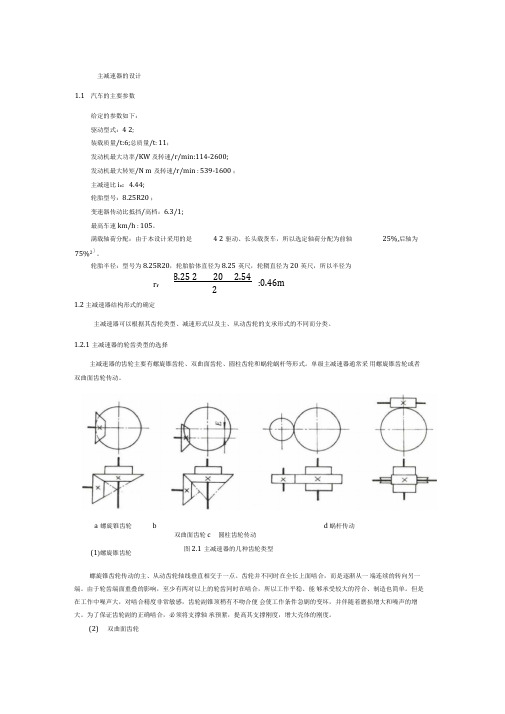
轮胎半径:型号为8.25R20,轮胎胎体直径为8.25英尺,轮辋直径为20英尺,所以半径为1.2 主减速器结构形式的确定主减速器可以根据其齿轮类型、减速形式以及主、从动齿轮的支承形式的不同而分类。
1.2.1主减速器的轮齿类型的选择主减速器的齿轮主要有螺旋锥齿轮、双曲面齿轮、圆柱齿轮和蜗轮蜗杆等形式。
单级主减速器通常采 用螺旋锥齿轮或者双曲面齿轮传动。
双曲面齿轮 c 圆柱齿轮传动 图2.1主减速器的几种齿轮类型螺旋锥齿轮传动的主、从动齿轮轴线垂直相交于一点。
齿轮并不同时在全长上面啮合,而是逐渐从一 端连续的转向另一端。
由于轮齿端面重叠的影响,至少有两对以上的轮齿同时在啮合,所以工作平稳、能 够承受较大的符合、制造也简单。
但是在工作中噪声大,对啮合精度非常敏感,齿轮副锥顶稍有不吻合便 会使工作条件急剧的变坏,并伴随着磨损增大和噪声的增大。
为了保证齿轮副的正确啮合,必须将支撑轴 承预紧,提高其支撑刚度,增大壳体的刚度。
(2) 双曲面齿轮r r8.25 220 2.542:0.46ma 螺旋锥齿轮 b(1)螺旋锥齿轮d 蜗杆传动双曲面齿轮传动的主、从动齿轮的轴线相互垂直而不相交。
主动齿轮轴相对于从动齿轮轴有向上或向下的偏移,称这个偏移量称为双曲面齿轮的偏移距。
所以主动齿轮的螺旋角比从动齿轮较大一些。
当螺旋锥齿轮和双曲面齿轮两种传动形式主从动齿轮外径、齿面宽以及主动齿轮齿数都相同时,双曲面齿轮由于主动齿轮的螺旋角的增大,使主动齿轮的节圆直径大约比螺旋锥齿轮大20%左右。
单级主减速器设计步骤

一、单级主减速器设计步骤Step1 创建新文件1.启动PRO/E之后,建立一个新文件,文件类型选为零件,子类型为实体Step2 制作底座1.单击拉伸按钮,弹出拉伸工具控制面板;单击“放置”按钮,单击“定义”按钮,弹出草绘对话框。
选择TOP面作为草绘平面,其余接受默认设置。
单击草绘进入草绘模式。
2.绘制剖面,完成草绘。
3.属性面板中,拉伸方式为“可变”,拉伸长度为20.4.单击确认,完成拉伸特征。
Step3 切割底座1.单击拉伸按钮,弹出拉伸工具控制面板;单击“放置”按钮,单击“定义”按钮,弹出草绘对话框。
选择底座的底面作为草绘平面,其余接受默认设置。
单击草绘进入草绘模式2.绘制剖面,完成草绘。
3.属性面板中,拉伸方式为“穿透”,选择移除材料按钮。
4.单击确认,完成切剪特征。
如下图所示。
Step4 倒圆角1.单击倒圆角按钮2.属性面板中,设定倒圆角的半径为3.3.、选择切割特征上表面作为参照,单击确认,生成倒圆角特征。
Step5 制作主体1.单击拉伸按钮,弹出拉伸工具控制面板;单击“放置”按钮,单击“定义”按钮,弹出草绘对话框。
选择底座的上表面作为草绘平面,其余接受默认设置。
单击草绘进入草绘模式。
2.绘制剖面,完成草绘。
3.属性面板中,拉伸方式为“可变”,拉伸长度为150.4.单击确认,完成拉伸特征。
如图所示。
Step6 挖出部分体积1.单击基准平面按钮,选择底盘的切剪特征的上表面作为参照平面,偏移量设为8.2.单击确定按钮,创建基准平面DATM1。
3.单击拉伸按钮,弹出拉伸工具控制面板;单击“放置”按钮,单击“定义”按钮,弹出草绘对话框。
选择DATM1的上表面作为草绘平面,其余接受默认设置。
单击草绘进入草绘模式。
4.绘制剖面,完成草绘。
5.属性面板中,拉伸方式为“穿透”,选择移除材料按钮。
6.单击确认,完成切剪特征。
如下图所示。
Step7 制作底座上的安装孔1.单击孔工具按钮,弹出孔工具控制面板。
汽车单级主减速器设计本汽设_鱿鱼(完成)

汽车单级主减速器设计本汽设_鱿鱼(完成)toprovideacommontransmissionratioforeachgear.Atransmissionoutputisaro undthelongitudinalaxisofrotationofthetorque,thewheelshavetogoaroundth ehorizontalaxisrotationofthevehicle,whichrequiresadevicetochangethedi rectionofthetransmissionofpower.Iscalledamaingearbox,becauseregardles softransmission,thegeartransmission ratioofthisdeviceare thetotaltra nsmissionratioofafactor.Withthistransmissionratio,caneffectivelyreduc etheabilitytoslowdowntransmission,thebenefitsofthisdesigncaneffective lyreducethesizeofthetransmission,sothatthegeneralarrangementofthevehi cleamorereasonableAutomaingearboxofthemostimportantroleistoslowtheincreaseintwist.W eknowthattheengineoutputpoweriscertain,togetarelativelyhighoutputtorq ue,largerdrivingforce.Inaddition,theautomotivemaingearboxtochangethed irectionofpoweroutput,leftandrightwheeldifferentialorrearaxledifferen tialfeatures.Keywords:transmissionsystem;driveshaft;mainreducer目录1课程设计目的12单级主减速器结构方案分析22.1主减速器的的结构形式22.1.1主减速器齿轮的类型22.1.2主减速器主动锥齿轮的支承型式及安置方法33.1作用在主减速器主动齿轮上的力283.2主减速器轴承载荷的计算323.3主减速器轴承的当量载荷及寿命33 4主减速器齿轮的材料及热处理365主减速器的润滑37课程设计总结38参考文献39致谢4020°、轴交角为90的螺旋齿轮)汽车主减速器锥齿轮的工作条件非常恶劣,与传动系其它齿轮相比较,具有载荷大、作用时间长、变化多、有冲击等特点。
整体式单级主减速器设计

整体式单级主减速器设计2.1 主减速器结构方案设计主减速器的结构形式主要是根据齿轮类型、主动齿轮和从动齿轮的安置方法以及减速形式的不同而不同。
主减速器的齿轮主要有螺旋锥齿轮、双曲面齿轮、圆柱齿轮和蜗轮蜗杆等形式。
单级主减速器通常采用螺旋锥齿轮或双曲面齿轮传动。
2.1.1螺旋锥齿轮传动螺旋锥齿轮传动(图2-1a)的主、从动齿轮轴线垂直相交于一点,齿轮并不同时在全长上啮合,而是逐渐从一端连续平稳地转向另一端。
另外,由于轮齿端面重叠的影响,至少有两对以上的轮齿同时啮合,所以它工作平稳、能承受较大的负荷、制造也简单。
但是在工作中噪声大,对啮合精度很敏感,齿轮副锥顶稍有不吻合便会使工作条件急剧变坏,并伴随磨损增大和噪声增大。
为保证齿轮副的正确啮合,必须将支承轴承预紧,提高支承刚度,增大壳体刚度。
图2-1 主减速器齿轮传动形式a)螺旋锥齿轮传动b)双曲面齿轮传动c)圆柱齿轮传动d)蜗杆传动2.1.2 双曲面齿轮传动双曲面齿轮传动(图2-1b)的主、从动齿轮的轴线相互垂直而不相交,主动齿轮轴线相对从动齿轮轴线在空间偏移一距离E,此距离称为偏移距。
由于偏移距E的存在,使主动齿轮螺旋角大于从动齿轮螺旋角(图6-4)。
根据啮合面上法向力相等,可求出主、从动齿轮圆周力之比(2-1)图2-2双曲面齿轮副受力情况式中,F1、F2分别为主、从动齿轮的圆周力;β1、β2分别为主、从动齿轮的螺旋角。
螺旋角是指在锥齿轮节锥表面展开图上的齿线任意一点A的切线TT与该点和节锥顶点连线之间的夹角。
在齿面宽中点处的螺旋角称为中点螺旋角(图2-2)。
通常不特殊说明,则螺旋角系指中点螺旋角。
双曲面齿轮传动比为(2-2)式中,——双曲面齿轮传动比;、分别——主、从动齿轮平均分度圆半径。
螺旋锥齿轮传动比为(2-3)令,则。
由于>,所以系数K>1,一般为1.25~1.50。
这说明:1)当双曲面齿轮与螺旋锥齿轮尺寸相同时,双曲面齿轮传动有更大的传动比。
汽车主减速器设计流程

汽车主减速器设计流程下载温馨提示:该文档是我店铺精心编制而成,希望大家下载以后,能够帮助大家解决实际的问题。
文档下载后可定制随意修改,请根据实际需要进行相应的调整和使用,谢谢!并且,本店铺为大家提供各种各样类型的实用资料,如教育随笔、日记赏析、句子摘抄、古诗大全、经典美文、话题作文、工作总结、词语解析、文案摘录、其他资料等等,如想了解不同资料格式和写法,敬请关注!Download tips: This document is carefully compiled by theeditor. I hope that after you download them,they can help yousolve practical problems. The document can be customized andmodified after downloading,please adjust and use it according toactual needs, thank you!In addition, our shop provides you with various types ofpractical materials,such as educational essays, diaryappreciation,sentence excerpts,ancient poems,classic articles,topic composition,work summary,word parsing,copy excerpts,other materials and so on,want to know different data formats andwriting methods,please pay attention!汽车主减速器设计流程主要包括以下几个步骤:1. 确定设计要求了解汽车的类型、用途、性能要求等。
单级主减速器@汽车底盘精品资源池
前言主减速器是汽车传动系中减小转速、增大扭矩的主要部件。
对发动机纵置的汽车来说,主减速器还利用锥齿轮传动以改变动力方向。
汽车正常行驶时,发动机的转速通常在2000至3000r/min左右,如果将这么高的转速只靠变速箱来降低下来,那么变速箱内齿轮副的传动比则需很大,而齿轮副的传动比越大,两齿轮的半径比也越大,换句话说,也就是变速箱的尺寸会越大。
另外,转速下降,而扭矩必然增加,也就加大了变速箱与变速箱后一级传动机构的传动负荷。
所以,在动力向左右驱动轮分流的差速器之前设置一个主减速器,可使主减速器前面的传动部件如变速箱、分动器、万向传动装置等传递的扭矩减小,也可以使变速箱的尺寸、质量减小,操纵省力。
现代汽车的主减速器,广泛采用螺旋锥齿轮和双曲面齿轮。
双曲面齿轮工作时,齿面间的压力和滑动较大,齿面油膜易被破坏,必须采用双曲面齿轮油润滑,绝不允许用普通齿轮油代替,否则将使齿面迅速擦伤和磨损,大大降低使用寿命。
主减速器的种类繁多:有单级式和双级式;有单速式和双速式;还有贯通式和轮边式等。
本文主要对轿车的单级主减速器进行设计。
11课题背景及意义主减速器是很多不同大小的齿轮组合而成的。
也许你见过可变速的自行车,它的后轮齿轮就是好几个大小不一的齿轮组合起来的,自行车通过链条传动,脚蹬处的齿轮大于后轮齿轮,则车速块,相反则省力也就是扭力大。
机动车的减速器是夹在发动机和传动轴之间的设备。
1、首先发动机转速是很高的,每分钟好几千转,不可能让发动机直接连接传动轴,否则车轮也会达到每分钟几千转,那是很恐怖的2、发动机通过小齿轮带动减速器的大齿轮,实现了转速的下降和动力的传递3、当减速器里不同大小的齿轮连接发动机时,传递到车轮的动力则不同:发动机的小带减速器的最大齿轮,则扭力最大,也就是机动车的一、而档位;发动机的小带减速器的最小齿轮,则车辆速度最高。
本文对汽车的主减速器进行设计主要是为了是汽车或得最佳的动力性能,能充分的利用发动机传递过来的转矩,由于今年了石油资源的紧缺,所以对减速器进行设计,使轿车或得最佳的动力性,对于提高汽车在市场上的竞争力有很大帮助。
单级主减速器设计步骤

一、单级主减速器设计步骤Step1 创建新文件1.启动PRO/E之后,建立一个新文件,文件类型选为零件,子类型为实体Step2 制作底座1.单击拉伸按钮,弹出拉伸工具控制面板;单击“放置”按钮,单击“定义”按钮,弹出草绘对话框。
选择TOP面作为草绘平面,其余接受默认设置。
单击草绘进入草绘模式。
2.绘制剖面,完成草绘。
3.属性面板中,拉伸方式为“可变”,拉伸长度为20.4.单击确认,完成拉伸特征。
Step3 切割底座1.单击拉伸按钮,弹出拉伸工具控制面板;单击“放置”按钮,单击“定义”按钮,弹出草绘对话框。
选择底座的底面作为草绘平面,其余接受默认设置。
单击草绘进入草绘模式2.绘制剖面,完成草绘。
3.属性面板中,拉伸方式为“穿透”,选择移除材料按钮。
4.单击确认,完成切剪特征。
如下图所示。
Step4 倒圆角1.单击倒圆角按钮2.属性面板中,设定倒圆角的半径为3.3.、选择切割特征上表面作为参照,单击确认,生成倒圆角特征。
Step5 制作主体1.单击拉伸按钮,弹出拉伸工具控制面板;单击“放置”按钮,单击“定义”按钮,弹出草绘对话框。
选择底座的上表面作为草绘平面,其余接受默认设置。
单击草绘进入草绘模式。
2.绘制剖面,完成草绘。
3.属性面板中,拉伸方式为“可变”,拉伸长度为150.4.单击确认,完成拉伸特征。
如图所示。
Step6 挖出部分体积1.单击基准平面按钮,选择底盘的切剪特征的上表面作为参照平面,偏移量设为8.2.单击确定按钮,创建基准平面DATM1。
3.单击拉伸按钮,弹出拉伸工具控制面板;单击“放置”按钮,单击“定义”按钮,弹出草绘对话框。
选择DATM1的上表面作为草绘平面,其余接受默认设置。
单击草绘进入草绘模式。
4.绘制剖面,完成草绘。
5.属性面板中,拉伸方式为“穿透”,选择移除材料按钮。
6.单击确认,完成切剪特征。
如下图所示。
Step7 制作底座上的安装孔1.单击孔工具按钮,弹出孔工具控制面板。
汽车主减速器设计说明书

目录摘要 (I)Abstract ................................................................................I I 第1章绪论 .. (1)1.1国内外主减速器行业现状和发展趋势 (1)1.2本设计的目的和意义 (2)1.3本次设计的主要内容 (2)第2章主减速器的设计 (3)2.1主减速器的结构型式的选择 (3)2.1.1主减速器的减速型式 (3)2.1.2主减速器齿轮的类型的选择 (4)2.1.3主减速器主动锥齿轮的支承形式 (6)2.1.4主减速器从动锥齿轮的支承形式及安置方法 (7)2.2主减速器的基本参数选择与设计计算 (8)2.2.1主减速比的确定 (8)2.2.2主减速器计算载荷的确定 (9)2.2.3主减速器基本参数的选择 (11)2.2.4主减速器双曲面齿轮的几何尺寸计算 (15)2.2.5主减速器双曲面齿轮的强度计算 (23)2.2.6主减速器齿轮的材料及热处理 (27)2.3主减速器轴承的选择 (28)2.3.1计算转矩的确定 (28)2.3.2齿宽中点处的圆周力 (28)2.3.3双曲面齿轮所受的轴向力和径向力 (29)2.3.4主减速器轴承载荷的计算及轴承的选择 (30)2.4本章小结 (34)第3章差速器设计 (35)3.1差速器结构形式的选择 (35)3.2对称式圆锥行星齿轮差速器的差速原理 (37)3.3对称式圆锥行星齿轮差速器的结构 (38)3.4对称式圆锥行星齿轮差速器的设计 (38)3.4.1差速器齿轮的基本参数的选择 (38)3.4.2差速器齿轮的几何计算 (40)3.4.3差速器齿轮的强度计算 (42)3.5本章小结 (43)第4章驱动半轴的设计 (44)4.1半轴结构形式的选择 (44)4.2全浮式半轴计算载荷的确定 (46)4.3全浮式半轴的杆部直径的初选 (47)4.4全浮式半轴的强度计算 (47)4.5半轴花键的计算 (47)4.5.1花键尺寸参数的计算 (47)4.5.2花键的校核 (49)4.6本章小结 (50)结论 (51)参考文献 (52)致谢 ................................................................错误!未定义书签。
最新单级主减速器设计步骤

单级主减速器设计步骤一、单级主减速器设计步骤Step1 创建新文件1.启动PRO/E之后,建立一个新文件,文件类型选为零件,子类型为实体Step2 制作底座1.单击拉伸按钮,弹出拉伸工具控制面板;单击“放置”按钮,单击“定义”按钮,弹出草绘对话框。
选择TOP面作为草绘平面,其余接受默认设置。
单击草绘进入草绘模式。
2.绘制剖面,完成草绘。
3.属性面板中,拉伸方式为“可变”,拉伸长度为20.4.单击确认,完成拉伸特征。
Step3 切割底座1.单击拉伸按钮,弹出拉伸工具控制面板;单击“放置”按钮,单击“定义”按钮,弹出草绘对话框。
选择底座的底面作为草绘平面,其余接受默认设置。
单击草绘进入草绘模式2.绘制剖面,完成草绘。
3.属性面板中,拉伸方式为“穿透”,选择移除材料按钮。
4.单击确认,完成切剪特征。
如下图所示。
Step4 倒圆角1.单击倒圆角按钮2.属性面板中,设定倒圆角的半径为3.3.、选择切割特征上表面作为参照,单击确认,生成倒圆角特征。
Step5 制作主体1.单击拉伸按钮,弹出拉伸工具控制面板;单击“放置”按钮,单击“定义”按钮,弹出草绘对话框。
选择底座的上表面作为草绘平面,其余接受默认设置。
单击草绘进入草绘模式。
2.绘制剖面,完成草绘。
3.属性面板中,拉伸方式为“可变”,拉伸长度为150.4.单击确认,完成拉伸特征。
如图所示。
Step6 挖出部分体积1.单击基准平面按钮,选择底盘的切剪特征的上表面作为参照平面,偏移量设为8.2.单击确定按钮,创建基准平面DATM1。
3.单击拉伸按钮,弹出拉伸工具控制面板;单击“放置”按钮,单击“定义”按钮,弹出草绘对话框。
选择DATM1的上表面作为草绘平面,其余接受默认设置。
单击草绘进入草绘模式。
4.绘制剖面,完成草绘。
5.属性面板中,拉伸方式为“穿透”,选择移除材料按钮。
6.单击确认,完成切剪特征。
如下图所示。
Step7 制作底座上的安装孔1.单击孔工具按钮,弹出孔工具控制面板。
汽车单级主减速器与车桥设计指导书
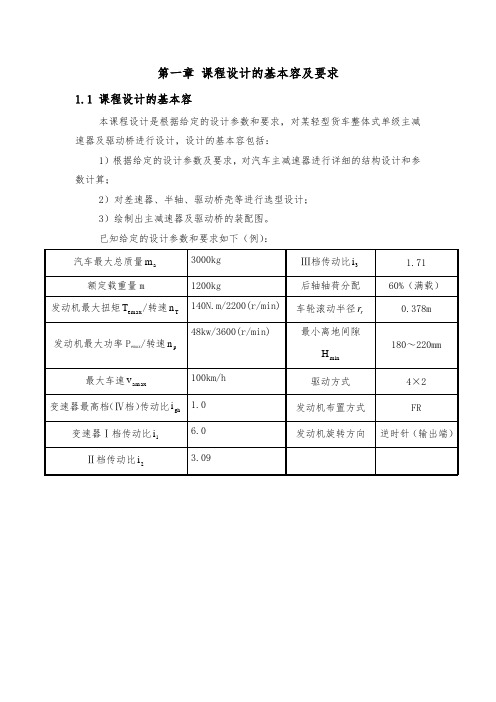
第一章课程设计的基本容及要求1.1 课程设计的基本容本课程设计是根据给定的设计参数和要求,对某轻型货车整体式单级主减速器及驱动桥进行设计,设计的基本容包括:1)根据给定的设计参数及要求,对汽车主减速器进行详细的结构设计和参数计算;2)对差速器、半轴、驱动桥壳等进行选型设计;3)绘制出主减速器及驱动桥的装配图。
已知给定的设计参数和要求如下(例):第二章 整体式单级主减速器设计2.1 主减速器的结构形式 1、主减速器齿轮的类型:现代汽车单级主减速器中多采用螺旋锥齿轮和双曲面齿轮两种。
(a ) 螺旋锥齿轮 (b ) 双曲面齿轮图1 主减速器齿轮类型1)螺旋锥齿轮如图1(a )所示,其主、从动齿轮轴线垂直相交于一点,且两者的螺旋角21ββ和相等,可知螺旋锥齿轮的传动比为:l l ol r r i 12= (2-1) 式中:l r 1、l r 2—螺旋锥齿轮主、从动齿轮的平均分度圆半径。
2)双曲面齿轮如图1(b )所示,主、从动齿轮轴线偏移了一个距离E ,称为偏移距, εββ,两者之差称为偏移角21>(如图2所示)。
根据啮合面上法向力相等,可求出主、从动齿轮圆周力之比为:2121cos cos ββ=F F (2-2) 式中:1F 、2F —双曲面齿轮主、从动齿轮的圆周力;1β、2β—双曲面齿轮主、从动齿轮的螺旋角。
图2 双曲面齿轮啮合时受力分析双曲面齿轮传动比为:11221122cos cos ββs s s s os r r r F r F i ==(2-3) 式中:1F 、2F —双曲面齿轮主、从动齿轮的圆周力;1β、2β—双曲面齿轮主、从动齿轮的螺旋角;s r 1、s r 2—双曲面齿轮主、从动齿轮的平均分度圆半径令12cos /cos ββ=K ,则s s os r Kr i 12/=。
由于21ββ>,所以1>K ,通常为1.25~1.50。
2、主减速器减速形式:主减速器的减速形式主要有单级减速、双级减速、双速、单级贯通式、双级贯通式和轮边减速等形式。
单级圆柱齿轮减速器设计说明

单级圆柱齿轮减速器设计说明一、设计原理齿轮副由主动轮和从动轮组成,一般情况下采用直齿轮、斜齿轮或锥齿轮。
当主动轮齿数大于从动轮齿数时,减速器为减速比大于1的减速器;反之,则为减速比小于1的增速器。
二、设计构造1.减速比选择:根据需要确定减速比,同时要考虑齿轮副的登齿系数、传动效率和材料强度等因素。
一般情况下,齿轮副的登齿系数应为1-1.5,传动效率应在0.95以上。
2.齿轮材料选择:根据工作条件和负载要求选择合适的齿轮材料。
常用的齿轮材料有20CrMnTi、40Cr、45#钢等,其中硬度要求一般在58-62HRC之间。
3.轴承选择:根据输出轴受力大小和转速要求选择合适的轴承。
一般情况下,使用圆柱滚子轴承或角接触球轴承,且滚动体要求使用钢球或钢针。
4.结构布局:根据设计空间和机器布局确定减速器的整体结构布局。
要考虑轴承的支座设计、润滑系统的布置、轴向气隙的调整等因素。
三、选型要点在进行单级圆柱齿轮减速器选型时,要综合考虑以下几个要点:1.转矩要求:根据输出负载的转矩要求选择减速器的额定转矩。
一般情况下,额定转矩应大于实际转矩的1.3-1.5倍。
2.转速要求:根据工作要求选择减速器的额定转速。
要注意减速器的最大转速和工作转速。
3.允许误差:根据传动精度要求选择减速器的精度等级。
一般情况下,选择高精度的减速器,以保证传动精度和稳定性。
4.安装方式:根据机械布局和安装条件选择减速器的安装方式。
常见的安装方式有法兰连接、挂牙连接等。
总结起来,单级圆柱齿轮减速器的设计需要考虑减速比、齿轮材料、轴承选择、结构布局等因素。
在选型时要综合考虑转矩要求、转速要求、允许误差和安装方式等因素,以满足实际应用需求。
单级主减速的设计
原来两个财富值下的,现在只售1个财富值。
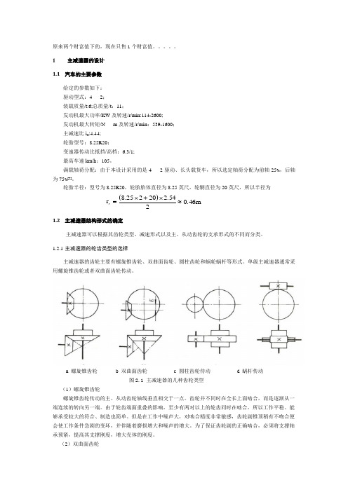
1主减速器的设计1.1 汽车的主要参数给定的参数如下: 驱动型式:42;装载质量/t:6;总质量/t :11;发动机最大功率/KW 及转速/r/min:114-2600; 发动机最大转矩/N m 及转速/r/min :539-1600;主减速比i 0:4.44; 轮胎型号:8.25R20;变速器传动比抵挡/高档:6.3/1; 最高车速km/h :105。
满载轴荷分配:由于本设计采用的是42驱动、长头载货车,所以选定轴荷分配为前轴25%,后轴为75%[2]。
轮胎半径:型号为8.25R20,轮胎胎体直径为8.25英尺,轮辋直径为20英尺,所以半径为 =r r ()m 6.4024.5220225.8≈⨯+⨯1.2 主减速器结构形式的确定主减速器可以根据其齿轮类型、减速形式以及主、从动齿轮的支承形式的不同而分类。
1.2.1 主减速器的轮齿类型的选择主减速器的齿轮主要有螺旋锥齿轮、双曲面齿轮、圆柱齿轮和蜗轮蜗杆等形式。
单级主减速器通常采用螺旋锥齿轮或者双曲面齿轮传动。
a 螺旋锥齿轮b 双曲面齿轮c 圆柱齿轮传动d 蜗杆传动图2.1 主减速器的几种齿轮类型(1)螺旋锥齿轮螺旋锥齿轮传动的主、从动齿轮轴线垂直相交于一点。
齿轮并不同时在全长上面啮合,而是逐渐从一端连续的转向另一端。
由于轮齿端面重叠的影响,至少有两对以上的轮齿同时在啮合,所以工作平稳、能够承受较大的符合、制造也简单。
但是在工作中噪声大,对啮合精度非常敏感,齿轮副锥顶稍有不吻合便会使工作条件急剧的变坏,并伴随着磨损增大和噪声的增大。
为了保证齿轮副的正确啮合,必须将支撑轴承预紧,提高其支撑刚度,增大壳体的刚度。
(2)双曲面齿轮双曲面齿轮传动的主、从动齿轮的轴线相互垂直而不相交。
主动齿轮轴相对于从动齿轮轴有向上或向下的偏移,称这个偏移量称为双曲面齿轮的偏移距。
所以主动齿轮的螺旋角比从动齿轮较大一些。
当螺旋锥齿轮和双曲面齿轮两种传动形式主从动齿轮外径、齿面宽以及主动齿轮齿数都相同时,双曲面齿轮由于主动齿轮的螺旋角的增大,使主动齿轮的节圆直径大约比螺旋锥齿轮大20%左右。
汽车单级主减速器设计

汽车单级主减速器设计任务书1.设计的主要任务及目标通过调研和查阅相关资料文献,掌握汽车单级主减速器主要用途和工作原理。
应用所学相关基础知识和专业知识,分析单级主减速器结构、载荷,对主要受力件强度进行计算分析,应用CAD三维造型或二维设计技术完成课题总成和关键零件结构设计和计算说明书,按照学校要求编写毕业设计论文。
2.设计的基本要求和内容1)掌握单级主减速器的结构及工作原理。
绘制结构简图和原理简图;2)了解零部件材料及制造、热处理工艺;3)了解单级主减速器的失效模式;4)制作单级主减速器的装配总图;5)对单级主减速器及关键零件结构进行计算分析,重点是对失效件的分析;6)编写毕业设计论文,总结设计取到的效果与体会,提出自己的论点和改进建议等。
3.主要参考文献《汽车车桥设计》4.进度安排汽车单级主减速器的设计摘要:由于行驶中的汽车发动机的转速通常在两千到三千转每分钟,如果只通过变速箱来减速的话,那样会有一个很大的减速比,从而增大了齿轮的半径,继而增大了变速箱的尺寸,既不经济又不合理,另外,转速下降,而扭矩必然增加,也就加大了变速箱与变速箱后一级传动机构的传动负荷。
所以,在动力向左右驱动轮分流的差速器之前设置一个主减速器。
主减速器的存在有三个作用,第一是改变动力传输的方向,由上图可以看出动力传递出变速器是纵向的力距,通过减速器,力矩发生了90度的转变,从而传递到半轴形成横向的力矩,从而驱动车子前进。
第二是作为变速器的延伸为各个档位提供一个共同的传动比。
有了这个传动比,可以有效的降低对变速器的减速能力的要求,这样设计的好处是可以有效减小变速器的尺寸,使车辆的总布置更加合理。
第三也是最重要的就是减速增扭,根据功率的计算公式W=M*v(功率=扭矩*速度)当功率一定时,减少传动速度,能够增加扭矩,从而增加驱动力,这也是汽车上坡采用低档的原因。
关键字;变速器,减速器,传动轴Automotive design single-stage main gearSummary:Since moving automobile engine speed is usually 2000-3000 rpm , if only to slow down through the gearbox , then that will be a big reduction ratio, thereby increasing the radius of the gear , which in turn increases the gearbox size , neither economic nor reasonable , in addition, the speed decreased, while torque will increase, it increases the load transmission gearbox and rear gearboxes level transmission mechanism . So, before power to the left and right wheels to set up a triage differential final drive .There exist three main reducer roleThe first is to change the direction of power transmission from the power transmission can be seen that the torque transmission is a longitudinal , through a speed reducer , torque in a shift of 90 degrees , thereby transferring torque to the transverse axle is formed so as to drive the car forward.Second, as an extension of a common transmission gear ratio for each gear position . With this ratio , can effectively reduce the transmission capacity reduction requirements , benefits of this design is that it can effectively reduce the size of the transmission , so that the general arrangement of the vehicle is more reasonable.The third and most important is the reduction by twisting , according to the power of the formula W = M * v ( power = torque * speed ) when the power is constant , the speed reduction gear , the torque can be increased , thereby increasing the driving force , which is the car reasons for the use of low-grade slope .Keywords; gearbox , reducer , drive shaft目录1 绪论 .................................................................................................................................. 1 2 单级主减速器的设计方案 .............................................................................................. 2 2.1汽车单级主减速器的结构及工作原理 ......................................................................... 2 2.1.1主减速器的类型 ......................................................................................................... 2 2.1.2主减速器的布置及作用分析 ..................................................................................... 4 2.1.3主减速器的减速形式 ................................................................................................. 5 2.1.4主减速器主、从动锥齿轮的支承方案的选择 ......................................................... 6 2.2主减速器的基本参数选择与设计计算 . (7)2.2.1主减速比0i 的确定 (7)2.2.2主减速齿轮计算载荷的确定 ..................................................................................... 8 2.3主减速器锥齿轮基本参数的选取 (9)2.3.1主、从动锥齿轮齿数1z 和2z ..................................................................................... 9 2.3.2 节圆直径和端面模数的选择 .................................................................................. 10 2.3.3 螺旋角的选择 ........................................................................................................... 11 2.3.4 齿面宽的选择 ........................................................................................................... 11 2.3.5螺旋锥齿轮螺旋方向 ................................................................................................ 11 2.3.6 齿轮法向压力角的选择 .......................................................................................... 12 2.4 主减速器锥齿轮几何尺寸的计算 .............................................................................. 12 2.5螺旋锥齿轮的失效形式 ............................................................................................... 15 2.6螺旋锥齿轮的强度校核 ............................................................................................... 16 2.6.1 单位齿长上的圆周力 .............................................................................................. 16 2.6.2 轮齿的弯曲强度计算 .............................................................................................. 17 2.6.3 轮齿的表面接触强度计算 ...................................................................................... 18 2.7锥齿轮的材料及热处理 ............................................................................................... 19 3 主减速器轴承的计算 ...................................................................................................... 20 3.1作用在主减速器齿轮齿宽中点的圆周力 ................................................................... 21 3.2 主减速器轴承载荷的计算 (22)总结 (25)参考文献 (26)致谢 (27)1 绪论1.1主减速器工作原理主减速器作为驱动桥的一部分,在汽车的传动系统中起到了很重要的作用,汽车的动力由变速器通过万向节,再由万向节通过主传动轴传递到主减速器,继而传递到驱动桥的另一个重要部分差速器,从而实现了汽车的平稳运转。
轿车和一般轻、中型货车均采用的主减速器——单级主减速器

轿车和一般轻、中型货车均采用的主减速器——单级主减速器
单级主减速器具有结构简单、体积小、质量轻和传动效率高等优点,所以轿车和一般轻、中型货车均采用单级主减速器。
图1(a)所示为东风EQ1090E型汽车驱动桥单级主减速器及差速器总成剖面图,图1(b)所示为该总成的零件分解图。
主减速器的减速传动机构为一对准双曲面齿轮18和7。
主动齿轮18有6个齿,从动齿轮7有38个齿,故主传动比i0=6.33。
为保证主动锥齿轮有足够的支承刚度,主动锥齿轮18与轴制成一体,前端支承在互相贴近而小端相向的两个圆锥滚子轴承13和17上,后端支承在圆柱滚子轴承19上,形成跨置式支承。
环状的从动锥齿轮7连接在差速器壳5上,而差速器壳则用两个圆锥滚子轴承3支承在主减速器壳4的座孔中。
在从动锥齿轮的背面,装有支承螺栓6,以限制从动锥齿轮过度变形而影响齿轮的正常工作。
装配时,支承螺栓与从动锥齿轮端面之间的间隙为0.3~0.5mm。
装配主减速器时,圆锥滚子轴承应有一定的装配预紧度,即在消除轴承间隙的基础上,再给予一定的压紧力。
其目的是为了减小在锥齿轮传动过程中产生的轴向力所引起的齿轮轴的轴向位移,以提高轴
的支承刚度,保证锥齿轮副的正常啮合。
但也不能过紧,若过紧则传动效率低,且加速轴承磨损。
为调整圆锥滚子轴承13和17的预紧度,在两轴承内座圈之间的隔离套的一端装有一组厚度不同的调整垫片14。
如发现过紧则增加垫片14的总厚度;反之,减小垫片的总厚度。
工程上常用预紧力矩表示预紧度的大小。
在本例中,调整到能以1.0~1.5N・m的力矩转动叉形凸缘11,即为合适。
【设计】单级主减速器

【关键字】设计前言主减速器是中减小转速、增大扭矩的主要部件。
对发动机纵置的汽车来说,主减速器还利用锥齿轮传动以改变动力方向。
汽车正常行驶时,发动机的转速通常在2000至3000r/min左右,如果将这么高的转速只靠来降低下来,那么变速箱内齿轮副的传动比则需很大,而齿轮副的传动比越大,两齿轮的半径比也越大,换句话说,也就是变速箱的尺寸会越大。
另外,转速下降,而扭矩必然增加,也就加大了变速箱与变速箱后一级传动机构的传动负荷。
所以,在动力向左右驱动轮分流的之前设置一个主减速器,可使主减速器前面的传动部件如变速箱、分动器、等传递的扭矩减小,也可以使变速箱的尺寸、质量减小,操纵省力。
现代汽车的主减速器,广泛采用螺旋锥齿轮和双曲面齿轮。
双曲面齿轮工作时,齿面间的压力和滑动较大,齿面油膜易被破坏,必须采用双曲面齿轮油润滑,绝不允许用普通齿轮油代替,否则将使齿面迅速揩伤和磨损,大大降低使用寿命。
主减速器的种类繁多:有单级式和双级式;有单速式和双速式;还有贯通式和轮边式等。
本文主要对轿车的单级主减速器进行设计。
1课题背景及意义主减速器是很多不同大小的齿轮组合而成的。
也许你见过可变速的自行车,它的后轮齿轮就是好几个大小不一的齿轮组合起来的,自行车通过链条传动,脚蹬处的齿轮大于后轮齿轮,则车速块,相反则省力也就是扭力大。
机动车的减速器是夹在发动机和传动轴之间的设备。
1、首先发动机转速是很高的,每分钟好几千转,不可能让发动机直接连接传动轴,否则车轮也会达到每分钟几千转,那是很恐怖的2、发动机通过小齿轮带动减速器的大齿轮,实现了转速的下降和动力的传递3、当减速器里不同大小的齿轮连接发动机时,传递到车轮的动力则不同:发动机的小带减速器的最大齿轮,则扭力最大,也就是机动车的一、而档位;发动机的小带减速器的最小齿轮,则车辆速度最高。
本文对汽车的主减速器进行设计主要是为了是汽车或得最佳的动力性能,能充分的利用发动机传递过来的转矩,由于今年了石油资源的紧缺,所以对减速器进行设计,使轿车或得最佳的动力性,对于提高汽车在市场上的竞争力有很大帮助。
- 1、下载文档前请自行甄别文档内容的完整性,平台不提供额外的编辑、内容补充、找答案等附加服务。
- 2、"仅部分预览"的文档,不可在线预览部分如存在完整性等问题,可反馈申请退款(可完整预览的文档不适用该条件!)。
- 3、如文档侵犯您的权益,请联系客服反馈,我们会尽快为您处理(人工客服工作时间:9:00-18:30)。
汽车单级主减速器设计任务书1.设计的主要任务及目标通过调研和查阅相关资料文献,掌握汽车单级主减速器主要用途和工作原理。
应用所学相关基础知识和专业知识,分析单级主减速器结构、载荷,对主要受力件强度进行计算分析,应用CAD三维造型或二维设计技术完成课题总成和关键零件结构设计和计算说明书,按照学校要求编写毕业设计论文。
2.设计的基本要求和内容1)掌握单级主减速器的结构及工作原理。
绘制结构简图和原理简图;2)了解零部件材料及制造、热处理工艺;3)了解单级主减速器的失效模式;4)制作单级主减速器的装配总图;5)对单级主减速器及关键零件结构进行计算分析,重点是对失效件的分析;6)编写毕业设计论文,总结设计取到的效果与体会,提出自己的论点和改进建议等。
3.主要参考文献《汽车车桥设计》4.进度安排汽车单级主减速器的设计摘要:由于行驶中的汽车发动机的转速通常在两千到三千转每分钟,如果只通过变速箱来减速的话,那样会有一个很大的减速比,从而增大了齿轮的半径,继而增大了变速箱的尺寸,既不经济又不合理,另外,转速下降,而扭矩必然增加,也就加大了变速箱与变速箱后一级传动机构的传动负荷。
所以,在动力向左右驱动轮分流的差速器之前设置一个主减速器。
主减速器的存在有三个作用,第一是改变动力传输的方向,由上图可以看出动力传递出变速器是纵向的力距,通过减速器,力矩发生了90度的转变,从而传递到半轴形成横向的力矩,从而驱动车子前进。
第二是作为变速器的延伸为各个档位提供一个共同的传动比。
有了这个传动比,可以有效的降低对变速器的减速能力的要求,这样设计的好处是可以有效减小变速器的尺寸,使车辆的总布置更加合理。
第三也是最重要的就是减速增扭,根据功率的计算公式W=M*v(功率=扭矩*速度)当功率一定时,减少传动速度,能够增加扭矩,从而增加驱动力,这也是汽车上坡采用低档的原因。
关键字;变速器,减速器,传动轴Automotive design single-stage main gearSummary:Since moving automobile engine speed is usually 2000-3000 rpm , if only to slow down through the gearbox , then that will be a big reduction ratio, thereby increasing the radius of the gear , which in turn increases the gearbox size , neither economic nor reasonable , in addition, the speed decreased, while torque will increase, it increases the load transmission gearbox and rear gearboxes level transmission mechanism . So, before power to the left and right wheels to set up a triage differential final drive .There exist three main reducer roleThe first is to change the direction of power transmission from the power transmission can be seen that the torque transmission is a longitudinal , through a speed reducer , torque in a shift of 90 degrees , thereby transferring torque to the transverse axle is formed so as to drive the car forward.Second, as an extension of a common transmission gear ratio for each gear position . With this ratio , can effectively reduce the transmission capacity reduction requirements , benefits of this design is that it can effectively reduce the size of the transmission , so that the general arrangement of the vehicle is more reasonable.The third and most important is the reduction by twisting , according to the power of the formula W = M * v ( power = torque * speed ) when the power is constant , the speed reduction gear , the torque can be increased , thereby increasing the driving force , which is the car reasons for the use of low-grade slope .Keywords; gearbox , reducer , drive shaft目录1 绪论 .................................................................................................................................. 1 2 单级主减速器的设计方案 .............................................................................................. 2 2.1汽车单级主减速器的结构及工作原理 ......................................................................... 2 2.1.1主减速器的类型 ......................................................................................................... 2 2.1.2主减速器的布置及作用分析 ..................................................................................... 4 2.1.3主减速器的减速形式 ................................................................................................. 5 2.1.4主减速器主、从动锥齿轮的支承方案的选择 ......................................................... 6 2.2主减速器的基本参数选择与设计计算 . (7)2.2.1主减速比0i 的确定 (7)2.2.2主减速齿轮计算载荷的确定 ..................................................................................... 8 2.3主减速器锥齿轮基本参数的选取 (9)2.3.1主、从动锥齿轮齿数1z 和2z ..................................................................................... 9 2.3.2 节圆直径和端面模数的选择 .................................................................................. 10 2.3.3 螺旋角的选择 ........................................................................................................... 11 2.3.4 齿面宽的选择 ........................................................................................................... 11 2.3.5螺旋锥齿轮螺旋方向 ................................................................................................ 11 2.3.6 齿轮法向压力角的选择 .......................................................................................... 12 2.4 主减速器锥齿轮几何尺寸的计算 .............................................................................. 12 2.5螺旋锥齿轮的失效形式 ............................................................................................... 15 2.6螺旋锥齿轮的强度校核 ............................................................................................... 16 2.6.1 单位齿长上的圆周力 .............................................................................................. 16 2.6.2 轮齿的弯曲强度计算 .............................................................................................. 17 2.6.3 轮齿的表面接触强度计算 ...................................................................................... 18 2.7锥齿轮的材料及热处理 ............................................................................................... 19 3 主减速器轴承的计算 ...................................................................................................... 20 3.1作用在主减速器齿轮齿宽中点的圆周力 ................................................................... 21 3.2 主减速器轴承载荷的计算 (22)总结 (25)参考文献 (26)致谢 (27)1 绪论1.1主减速器工作原理主减速器作为驱动桥的一部分,在汽车的传动系统中起到了很重要的作用,汽车的动力由变速器通过万向节,再由万向节通过主传动轴传递到主减速器,继而传递到驱动桥的另一个重要部分差速器,从而实现了汽车的平稳运转。
