联力PC-B12手册
BPLA编程手册V1.7

+ (连>续)域 递增数字(字母) ...............................3.0 ...... - (连<续)域 递减数字(字母) ...............................3.0 ...... ^ 设置相同标签的打印数量 .................................3.0 ..... & 设置连续域的位置 ...................................3.0 ......
- 2 -
BPL编A程手册
STX 开J启Z/ 关闭蜂鸣器报警功能 ..............................1.7 ..... STX 打J印Y机 纵向打印位置调整 指令 ............................1.7 ...... STX 系K统 扩展指令 ...................................1.7 ...... STX 检k测 RS-2串3口2..................................1.7 ...... STX 进L入 标签格式指令 .................................1.7 ...... STX 设l置镜像打印 ....................................1.7 ...... STX 设M置 寻找标签的最大长度 ..............................1.8 ...... STX 设m置 打印机计量单位为米制 .............................1.8 ...... STX 设N置 打印机计量单位为点制 .............................1.8 ...... STX 设n置 打印机计量单位为英制 ..............................1.8 ..... STX 切o刀 测试 ......................................1.8 ...... STX 打p印 暂停 ......................................1.8 ...... STX 清Q除 所有模块的内容 ................................1.8 ...... STX 清q除 指定模块的内容 .................................1.9 ..... STX 选r择 反射传感器 ...................................1.9 ...... STX 设S置 进纸速度 ....................................1.9 ...... STX 进s入 单缓冲工作模式 .................................1.9 ..... STX 打T印 打印头测试样张 .................................1.9 ..... STX 检t测 RAM模块 ....................................1.9 ...... STX 标U签 域替换 ....................................1.9 ...... STX 设u置 旋转打印 ....................................2.0 ...... STX 返v回 当前版本信息 ..................................2.0 ..... STX 返W回 内存配置信息 .................................2.0 ...... STX 检w测 FLAS模H块 ..................................2.1 ...... STX 从x模 块中删除指定文件 ................................2.1 ..... STX 输Y出 传感器的值 ..................................2.3 ...... STX 打Z印 内部信息和打印头测试样张 ...........................2.3 ...... STX 压z缩 模块 ......................................2.3 ...... * 注释行.........................................2.3 ......
ATV12变频器安装及编程手册-6

71
配置模式 - 完整菜单 (FULL)
I-OdrCCtLFUNFLtCOM-
代码 FUn-
PId-
AC2
T
名称 / 说明
调整范围
出厂设置
功能菜单 ( 续 )
PID 菜单 ( 续 )
M 第 2 加速时间
0.0 至 999.9 s
5.0 s
此参数仅会在系统起动时激活。 第 2 加速斜坡时间可调范围为 0.1 - 999.9 s。 从 0 加速到电机额定频率 FrS( 第 55 页 ) 所用的时间,应确保此值与被驱动负载的惯量相一致。
功能菜单 ( 续 )
PID 菜单 ( 续 )
M 4 个预置 PID 分配
nO
vv v v v
仅在 PID 反馈分配 PIF ( 第 70 页 ) 设置不为 nO 时,此参数可见。 无 L1h L2h L3h L4h
在指定 4 个预置 PID 分配 Pr4 之前,必须先指定 2 个预置 PID 分配 Pr2( 第 70 页 )。
PII
nO YES
M 激活内部 PID 给定
v v
仅在 PID 反馈分配 PIF 设置不为 nO 时,此参数可见。 否
是
Pr2
nO L1H L2H L3H L4H
M 2 个预置 PID 分配
vv v v v
仅在 PID 反馈分配 PIF 设置不为 nO 时,此参数可见。 无 L1h L2h L3h L4h
手动故障复位 功能未激活 L1h: LI1 高电平有效 L2h: LI2 高电平有效 L3h: LI3原因已经消失,当被赋值的输入或寄存器位变为 1 时故障复位。
图形显示终端上的 STOP/RESET 按钮可执行相同的功能。
IT-12D Ver_2.0 IT-12M 用户手册说明书

INTERPRETATIONIT-12D Ver_2.0IT-12M SYSTEMUser’s ManualImportant NoticeAll the safety and instructions for operation and use of the equipment should be read carefully• before the system is operated.Please keep this user manual for future reference.• Please follow all the operation instructions.• Cleaning: Make sure to turn off the power supply before cleaning. Use a dry soft cloth to clean • the equipment.Don’t leave the product in a place with high humidity and temperature.• Do not use any accessory, which is not recommended by the manufacturer .• Do not place the equipment on an unstable stand; Please use appropriate package or original • package by the manufacturer before transport to avoid damage caused by strong shake during transporting.Adequate ventilation is good for the maintenance of the equipment.• Power supply AC 100-240V.• Grounding: 3-wire grounding plug.• Hot swapping is prohibited.• Total 11 sets of IT-12D can be connected in one system. The cumulative cable • length should not exceed 70 meters. For particular requirement, please contact the nearest JTS Service Centre for information.For service, please contact the nearest JTS Service Centre. Do not take the equipment apart by • unauthorized personnel.All JTS products are guaranteed for 1 year except for the cases as follows caused by personal • reasons:A : Damage or malfunction caused by personal factors such as dropping, striking and so on.B : Damage or malfunction caused by improper handling of the operator.C : Parts loss or damage by taking apart by a unauthorized personal.Only use JTS tailor-made cables to connect the system.• Turn off the power supply and unplug the equipment from the power supply in case the • equipment is not in use for a long time.Upon receipt of the product, please fill out the Warranty Card enclosed and post it to JTS • Service Centre nearby in your region.TO REDUCE THE RISK OF ELECTRIC SHOCK,DO NOT EXPOSE THIS EQUIPMENT TO RAIN OR MOISTURE.WARNING:To prevent fire or shock hazard,do not expose units to rain or moistureCAUTION: To reduce the risk of electric shock, DO NOT open covers, no useable serviceable parts inside. Refer servicing to qualified service personnel onlyThis label may appear on the bottom of the unit due to space limitations.The lightning flash with an arrowhead symbol,with an equilateral triangle, is intended to alert the user to the presence of uninsulated dangerous voltage within the products enclosure that may be of sufficient magnitude to constitute a risk of electric shock to persons.The exclamation mark within an equilateral triangle is intended to alert the user to thepresence of imporyant operating and maintenance (servicing)instructions in the literature accompanying the appliance.Attention: Installation should be performed by qualified service personnel only in accordance with the National Electrical or applicable local codes.Power Disconnect: Units with or without ON - OFF switches have power supplied to the unit whenever the power cord is inserted into the power source; however,the unit is operational only when the ON - OFF switch is in the ON position. The power cord is the main power disconnect for all units.1. System Introduction2. Product Introduction2-1 Language Distributor // IT-12M2-2 Interpreter Console // IT-12D2-3 Accessories3. System Installation & Connection3-1 General Description3-2 System Connection // Connection Cables3-3 Connection of Audio Cables3-4 System Mounting Instructions4. System Setup & Operation5. Technical Data 1 2 2 4 7 8 8 9 10 12 13 15INDEXRemark:JTS Company reserves the right to modify any issue without notice in advance.If any detailed information needed, please contact the local agent or JTS distributor in your region. JTS is the registered trademark of JTS Professional Co., Ltd.1The JTS IT-12 interpretation system consists of IT-12M and IT-12D.• The IT-12M works as main unit to provide power, input and output interface, and control.• The IT-12D is an interpreter console allowing two interpreters work together. Interpreters can• choose either floor channel for original language for direct interpretation or relay interpretation available via the relay select key.For small venue crossing interpretation is available here.• The whole system supports 11 interpreter consoles for simultaneous interpretation and delivers • 12 languages to audiences.The product is a stand along system. It is compatible with any conference system. So no matter • a new installation or an existing project needing expansion with interpretation IT-12 can easily meet the requirement.Together with JTS wireless system and any infrared system more audiences can participate in a • conference.INTERPRETATION SYSTEM22-1 Language Distributor // IT-12MCOMBO socket microphone input: This COMBO socket provides +48V Phantom power to a microphone with balanced XLR or unbalanced φ6.3 connector. The input signal will be mixed with the Original (CH0).Gain: Adjust input sensitivity of the COMBO socket. The adjustable range is ±10dB.Interpreter channel indicator: Light-On to indicate the correspondent channel is active. Flashing to indicate the correspondent channel is standby.Signal level indicator: the brightness of this LED indicates the signal level of the cor-respondent channel. Power on indicator (Red).Power Switch: Push the”│” on this switch will be turn system on, and push the”○” on this switch will turn system off.Power supply socket (3-wire grounding plus) with built in fuse, T2A/250V.DC power output: The IT-12M includ 12 outputs of DC power supply (+15V/500mA) to wireless transmitters, like JTS TG-10STX tabletop wireless transmitter.Interpreter console interface (D-sub 25pin socket):11 interpreter consoles can be connected in daisy chain (IT-12D).Record IN connector (RCA): external signal from play back devices will be mixed with the Original (CH0) for recording.Record output connector (RCA): Connect to recording equipment. The original signal (CH0) mixed with REC. IN will be recorded.12345678910113Original (CH0, floor channel) output (RCAx2/symmetrical output) : Original (CH0) balanced output with RCA connecters.12CH audio output interface: #0 to 11 correspond to the Original (CH 0) and 11 sets of Interpreter Consoles. Signals are for distribution to audiences via JTS wireless systems. Notice: any channel not in use will be assigned with CH0 as input.Original (CH0) volume control: This potentiometer adjusts the Original (CH0) sensitivity. Adjustable range is ±10dB.Original (CH0) input socket: This φ6.3mm balanced connecter is connected to an output of a conference system or PA as the original signal of the interpretation system.Alarm sound input:φ6.3mm jack / unbalanced input.Slow output: When a Slow Key on the IT-12D is activated this Slow output will generate an 1 sec. pulse to request the lecturer to slow down.Alarm control input: A short cut of Alarm Ctrl. and GND will activate alarm procedure. All channels will receive alarm signal, and indicator LED will change from Light-On to Flashing.121314151617182-2 Interpreter Console // IT-12DENTER key: To set the active channel of interpreter console. When switch on Switchthe ENTER indicator starts flashing. After push one of the selectable channels (fromCH1 to CH11 with Light On) this active channel can be stored to this interpreterconsole by pushing the ENTER key. Then switch off the Switch to end the procedure.CH1~CH11 Channel Output Key:• MODE switch at LOCK position: Under setting state, press it to select a selectable chan-nel (indicator on) for interpretation output. Only 1 channel can be set in one InterpreterConsole. The indicator of the activate channel is in green.• MODE switch at OPEN position: All of channel indicator are off when power oninitially. All channels are open to interpreter as long as it is not occupied by others. Whenthe channel is activated the Channel Output Key is in green. The indicator flashes in redwhich means this channel is in use by others.Note: MIC. ON/OFF at OFF state, the activate channel will be releasedwhen this channel number on other interpreter console is selected.19282820INTERPRETATION SYSTEM45Relay interpretation monitor (MONITOR): After pressing RELAY key, an interpreter can turn the monitor rotary knob to select an interpreted language he/she can understand to interpret.Headphone volume control (VOLUME A, VOLUME B): To adjust the volume of the headphones.Relay interpretation switch (RELAY): In case the interpreter doesn’t understand the original language, they can press the key and switch Monitor to another interpreted language from other interpreter for further interpretation.Floor Channel Switch (ORIGINAL): When the system start, the setting is by default, press it to listen to the original language (the speech from CH0).Mute Key (COUGH CUT): In case the interpreter coughs. Keep pressing the key to mute the line, meanwhile the indicator is on. When released, the line returns to working status.MIC ON/OFF button (MIC.A ON/OFF, MIC.B ON/OFF): Press it to turn the microphone on, the indicator will be on. Press it again to turn off the MIC.Only one microphone can be on at a time. MIC. A and MIC. B will override each other.Reminder key (SLOW): In case the delegate speaks too fast for the interpreter to follow, press it to request the delegate to slow down.MODE setting switch (OPEN / LOCK): The MODE switch needs be decided before power on. At the OPEN mode an interpreter can activate any channel in any time as long as it is not occupied. All channels are set off at the initial state, then an interpreter must select channel key which he wants. At the LOCK mode the interpreter can choose only one output channel which will not be taken by other users (setting procedure refer tostep and “System and Operation” chapter for more detail).Setting switch (SET): When all Interpreter Console are connected, setting of a channel of each console is needed for first time installation at LOCK mode. First turn the Switch to “ON”, the ENTER key will start flashing. According to above Step No.20 to select onechannel for the console. Then turn the Switch to “OFF” to finish the channel setting.To starting the channel setting procedure just turn the setting switches (SET) from “OFF”to “ON”. Finish the channel setting procedure by turn the setting Switch from “ON”to “OFF”.XLR microphone input: Each interpreter unit including 2 balanced XLR microphone input sockets with +48V Phantom power. These balanced microphones will be mixed with MIC. A/B.Input interface (INPUT): to connect the first Interpreter Unit to the IT-12M and the second one to the Output interface of the first unit (25-pin socket).29292929222123242526272829303132 33 34 35Output interface (OUTPUT): for connection with the next Interpreter Unit (25-pin plug).Recorder interface (REC OUT): φ3.5mm stereo, for connection with a recorder to record the interpretation. (Available on both left and right side of the Interpreter Console).Microphone input (MIC IN): φ3.5mm dummy stereo, for connection with microphone(Available on both left and right side of the Interpreter Console). Earphone output (EARPHONE):φ3.5mm stereo, for connection with interpreter headset (Available on both left and right side of the Interpreter Console).INTERPRETATION SYSTEM 62-3 AccessoriesAccessories are standard parts for a complete system installation, general description are as follow:IT-12-C3: 3 meter cable with D-sub 25-pin M/F on each end.Used to connect Interpreter Console (IT-12D) in daisy chain and to IT-12M.•Connecters: 1 Plug, 1 Socket.•3.System Installation & Connection3-1 General DescriptionIT-12 Interpreter System has a compact dimension and is easy for installation. IT-12Dinterpreter consoles are connected in daisy chain and the first IT-12D is connected to themain unit IT-12M.A detailed description of IT-12 Interpreter System installation and connection will begiven by diagrams and examples in this chapter.3-2 System Connection // Connection CablesAll consoles are connected via D-Sub 25-pin cable. A 25-pin 3 meter cable (with a plugand a socket) is included in each IT-12D Interpreter Console to connect the interpreterunit to Main Unit IT-12M or to each other. On the rear panel of IT-12D there are twoD-Sub connecters, the “INPUT” is a plug and the “OUTPUT” a socket. Connect theplug from the 25-pin cable to the Main unit IT-12M then the socket from the 25-pincable to the plug “INPUT” on the first Interpreter Console. And then connect the plugof the second 25-pin cable to the socket “OUTPUT” of the first Interpreter Console and the socket is connected to the plug “INPUT” of the next Interpreter Console. Then all the interpreter units are connected in daisy chain. As many as 11 interpreter units can beconnected for 12 languages (including floor channel) interpretation. Extension cablescan be used between Interpreter Consoles and Main Unit IT-12M (IT-12-C3/C6/C12/ C18).It is strongly recommended to use JTS tailor-made cables to ensure the best performance.CH113-3 Connection of Audio CablesCable connection plays an important role in the long distance audio transmission. Improper connection will result in interference. For example:(1)Connection for Unbalanced to Balanced transmission cable:Practical example: after the audios from signal source of mono RCA output, they go through to the IT-12M balanced input “LINE IN” (φ6.3mm jack) via unbalanced output.GND(SHIELD)shielded netBAL. + OR UNBAL.HI.BAL. - OR UNBAL.LO.353637* Note: This connection is not applicable to Balanced to Unbalanced transmission. Otherwise, the signal source of balanced output may be damaged.(2)Connection for Balanced to Balanced transmission cable:Practical example: After the audios from wired and/or wireless microphones are mixed via the mixer, they go through to the IT-12M balanced input “LINE IN” (φ6.3mm jack) via balanced output.(3)Connection for Unbalanced to Balanced XLR transmission cable:Practical example: the recording output of IT-12M “REC. OUT” (unbalanced output) to PA system or media recording input XLR interface (balanced input).* Note: This connection is not applicable to Balanced to Unbalanced transmission. Otherwise, the signal source of balanced output may be damaged.3-4 System Mounting InstructionsIT-12M Main unit Installation(1)Dimension (LxWxH):421 x 213 x 44mm (2)Colour: Silvery black (3)Weight:2.65Kg(4)“L” shape rack mount bracket for 1U 19-inch standard cabinet.(5)Mounting InstructionsA pair of rack mount brackets are equipped with the IT-12M , unscrew the screwson both sides firstly , then fasten the brackets with these screws and put the IT-12Min the rack, finally install the unit onto the rack with 4 screws .3839404.System Setup & Operation4-1 General DescriptionThis chapter provides a comprehensive and detailed description on how to setup and op-erate IT-12 Interpreter System Main Unit (IT-12M) and Interpreter Console (IT-12D).(1)OPEN Mode: Interpreter Console Output Channel Select (IT-12D)Select the Console with one of the Channel Output key ‘1, 2… 11”; for example: Ifyou want this unit to be NO. 1; just press “1”. Then the indicator on the key will lighton in green while the channel is not occupied. If the indicator on the key flashes in redthat means the channel is occupied by other units. When the MIC. ON/OFF of theactivated channel is at OFF state, the activate channel could be released when otherinterpreter console selects the same channel number.(2)LOCK Mode: Interpreter Console Output Channel Select (IT-12D)Interpreter Console must be assigned with one unique output channel before beingused. The procedure is as:a.Make sure the connection is correct, and then turn on the IT-12M.b.Turn the “SET” setting switch from “OFF” on the rear panel of the InterpreterConsole to “ON”, the indicators of “ENTER” on the unit starts flashing. The indica-tors of available channels will turn RED. Pay attention only one channel can beactivated.c.Assign the Console with one of the Channel Output key “1,2….11”, for example:If you want this unit to be NO 1, just press “1”. Then the indicator on the key willchange to Green light, press “ ENTER ” key to store, the indicator of “ ENTER ”will keep light on;d.Turn the “SET” setting switch to “OFF”, the “ENTER” indicator will turn off, thatmeans the output channel selecting procedure is completed;e.If cross interpretation is needed OPEN mode should be selected.f.Repeat the same procedure (Steps b~d) to assign all the Interpreter Consoles.(3)To Cancel Selected Output Channel (only for LOCK mode)a.Turn the “SET” from “OFF” to “ON”.b.Push the “ENTER” for 3 seconds. Then all Channel Output Indicators will turn off.c.Turn the “SET” from “ON” to “OFF”. The Console will be of factory setting now.(4)The Operation of IT-12D Interpreter Console:The Interpreter Console is designed with digital technologies and used in conjunction with interpreter headset. Each Console allows two interpreters to work on it. The operation procedures are as follows:a.At LOCK mode, when the output channel is selected an interpreter only needpush the MIC ON/OFF key to activate the microphone or deactivate it.b.At OPEN mode, an interpreter can press any Output Channel key to deliver thecorrespondent language. The available channel will show a green indicator. A flash-ing red indicator means the channel is occupied.c.Put on the headset, adjust the microphone to an appropriate position and controlthe volume (Floor language is “ORIGINAL” as defaulted). Press “MIC. A/B ON/ OFF” to start the interpretation.d.In case the interpreter doesn’t understand the floor language. He/she can select alanguage familiar with from other interpreter for relay interpretation. First press“RELAY” key, the indicator will be on, and then switch the MONITOR to choose a familiar language for interpretation.e.In case the Interpreter wants to cough, keep pressing “COUGH CUT” key to cutoff the language output, release it to continue the interpretation.f.When the speaker speaks too fast for the interpreter to follow, the interpreter canpress “SLOW” key to remind the speaker to slow down. A pulse signal will comeout as remind from the IT-12M to the speaker desk.g.Each Interpreter Console accommodates A/B two interpreters to work, the opera-tion A/B interpreter is the same.5. Technical Data5-1 System environmental Conditions5-2 Main Unit IT-12M Technical DataTransport Temp.: -40○C~+70○C Operational Temp.: 0○C~+45○C Max. Relative humidity: <95%Item..................................................Power supply..............................System consumption...........DC power output..................D-SUB power output.........Line In sensitivity....................Alarm In sensitivity................MIC In sensitivity...................Alarm Ctrl....................................Slow output................................CH0~CH11 output level CH0 balance output level REC OUT output level.....REC IN input level................protocol.........................................Dimension (LxWxH).........Color................................................Weight............................................Specification 110-240Vac 90W+15V/0.3A*12DC+15V/2A-30dB±2dB LEVEL VR at MAX.-20dB±2dB-51dB±2dB Gain VR at MAX.Shorted to GND +12V,Pulse 1sec.180mV±20mV85mV-GND85mV±10mV 170mV±15mV -25dB±2dB RS-485421*213*44mm Silvery Black 2.65KgInterpretation Unit (IT-12D) Technical DataItem.................................................. Unit power................................... Unit power consumption. MIC sensitivity......................... XLR MIC sensitivity............ Earphone output level........ REC OUT output level..... Protocol......................................... In/Out interface...................... Dimension (LxWxH)......... Color................................................ Weight............................................SpecificationDC+15V100mA±10mA-45dB±2dB-45dB±2dB120mV±10mV at 33Ω load, volume MAX. 140mV±10mVRS-485D-Sub 25P plug and socket330*206*57mmSilvery-blue black2.5Kg。
PCL-812PG卡说明
PCL-812PG多功能数据采集卡使用说明书第一章概述这一章介绍PCL-812PG的背景信息包括关键特性、扩展性能、产品说明书1.1绪论PCL-812PG 是IBM PC/XT/AT及其兼容机的高性能、高速、多功能数据采集卡。
整卡的详尽说明书及齐全的第三方卖主的软件支持是PCL-812PG广泛的应用于工业及实验室环境下。
主要应用于数据采集、过程控制、自动检测、工厂自动控制。
1.2关键特性。
16位单端模拟输入通道。
一个工业标准的12位逐位逼近式A/D转换器(HADC574Z)用于转换模拟量输入。
在DMA模式下最大的A/D采样速率为30KHz。
软件可编程模拟输入序列。
双极性电压+/- 5V, +/- 2.5 V, +/- 1.25V +/- 0.625 V +/- 0.3125 V。
三种A/D触发模式。
软件触发器。
可编程步测触发器。
外部脉冲触发器。
程序控制A/D转换器的数据传输,中断处理器或DMA转换。
一个Intel 8253-5可编程定时器/计数器可提供以0.5 MHz-35minutes/pulse步测输出(触发脉冲),定时器的时间基准为2 MHz。
一个16位计数器保留给用户设置应用。
两个12位单集成多极性D/A输出通道。
一路输出可由板内-5V或-10V参考电压产生0-5V 或0-10V范围的输出。
这个参考电压精度来源于A/D转换器的参考电压精度。
外部直流或交流参考电压同样也可以用于产生其它D/A 输出。
16位TTL/DTL兼容数字输入、输出通道1.3 扩展性能为了增强PCL-812PG功能,可以通过以下可选子卡来扩展其功能。
PCLD-789放大器/乘法器卡这个功能强的前置模拟信号调理卡能在一个A/D输入通道中多路传输16路信号。
高级的仪表化的放大器提供开关选择增益,分别为0.5, 1, 2, 10, 50, 100, 200, 1000或任何用户自定义。
PCLD-787八通道同步采样保持前置卡该卡允许在小于30 ns通道间采样时间偏差下进行八通道模拟信号的同步采集。
联力工业电视软件操作手册

4.2 设置属性、网口、串口和开关量。
13 / 22
日期 文件名称
12.11.23
文件版本 V1.0
操作手册
4.3 设置摄像机属性、PTZ 和移动侦测。 摄像机属性可设置名称、描述(这两项可按需要,在虚拟矩阵中设置成井下位置和
煤矿名称,显示到调度室的大屏上)。 视频类的帧率、码率、制式、分辨率、码流、画质设置可根据摄像机类型和实际需
5 / 22
日期 文件名称
12.11.23
文件版本 V1.0
操作手册
1.2.2 输入远程登录的服务器的 IP 地址,10.224.92.163。点击“连接”。
1.2.3 在登录界面输入用户名和密码,用户名:administrator;密码:123。 右键点击右下角的“ ”图标,出现下图菜单,然后左键点击“设备”。
11 / 22
日期 文件名称
12.11.23
文件版本 V1.0
操作手册
当前回放时间及控 制按钮
当前回放的时间线
可以设置回放的 日期和时间
3.2 将需要回放录像的摄像机拖动到相应的视频窗口中,如上图。 3.3 选择需要回放录像的日期和时间,点击“播放”、“倒放”、“停止”等,
拖动速度滑块可控制播放的速度。
千兆光纤环网
KJJ18矿用本安型 网络交换机
阿利亚罗K-0169 Rev B 12通道多功能板说明书

12 Channels Multi-Function Board with AMPAL-1010 with AMP for SLSCThis document describes the SLSC AL-1010 with AMP for National Instruments SLSC-12001 chassis.OverviewThe AL-1010 is a 12-channel multi-function module to be connected between the Device Under Test (DUT) and the instrumentation part of the test system.The board is recommended for systems requiring high flexibility on the pin configurations.AL-1010 is made for National Instruments (NI) Switch Load Signal Conditioning (SLSC) system. The board is made to interface with NI PXI and/or Compact-RIO instrumentation devices for the purposes of test and validation of Electronic Control Unit (ECU) software and hardware. Custom device for VeriStand is included for Hardware-In-the-Loop applications.For larger applications, Aliaro Configurator is recommended for channel configuration. Contact Aliaro for additional information.C ontents Overview (1)Description (3)Features (3)Detailed description (4)Installation (5)Electromagnetic Compatibility (5)Unpacking the module (5)Hardware Installation (6)Maintenance (7)Safety (7)Before using the AL-1010 (7)System Check (7)Calibration (7)Specification (8)Definition and conditions (8)Environmental Characteristics (8)Physical characteristics (8)Front connectors (J1 & J2) (9)General specification (10)Fault Insertion (10)Signal conditioning (All channels) (10)Digital I/O (10)Analogue Out – Amplifier (10)Functions (11)LabVIEW (11)Veristand (11)Configuration and Accessories (12)RTI Backplane (12)AL-1010 RTI Terminal Block (14)Safety Guidelines (15)Product Certifications and Declarations (15)CE Compliance (15)Electromagnetic Compatibility Standards (15)Environmental Management (16)Waste Electrical and Electronic Equipment (WEEE) (16)DescriptionThe AL-1010 provide multiple functions for fault insertion, signal conditioning and digital I/O, including pulsed (PWM) signals. The AL-1010 is fitted in pair through the RTI-backplane AL-1010-RTI.The AL-1010 RTI backplane is needed to reach fully flexibility and enables easy connection to NI PXIe and/or Compact-RIO instrumentation devices. Additional with add-on boards the functionality can be expanded further.Features960V, 10A per channel912 independent and isolated channels in three banks9Two common buses per bank with switches to each channel9Brake up switch for each channel9Programmable level threshold on each channel9Parallel connection possibility for high current signals9LabVIEW driver is available.9Custom Device is available.Detailed descriptionFigure 1, AL-1010 Block diagramThe AL-1010 board provides fault insertion, signal conditioning and digital I/O.Fault insertion functions:- Open circuit (DUT to Load)- Short to + and – (DUT to AUX 1 or AUX2)Signal conditioning functions:- Digital input (from DUT) signal conditioning using adjustable threshold (-28 - +28V) - Analogue signal (to DUT) with amplification (4 channels)- Analogue signal (from DUT)Digital I/O functions:- Read digital status (from DUT) using adjustable threshold- Read PWM signals (from DUT) using adjustable threshold (Frequency and duty cycle) - Generate digital signals (to DUT) using AUX1 (+) and AUX2 (-)- Generate PWM signals (To DUT) using AUX1 (+) and AUX2 (-)InstallationElectromagnetic CompatibilityThis product is intended for use in industrial locations. However, harmful interference may occur in some installations, when the product is connected to a peripheral device or test object, or if the product is used in residential or commercial areas. To minimize interference with radio and television reception and prevent unacceptable performance degradation, install, and use this product in strict accordance with the instructions in the product documentation. Furthermore, any modifications to the product not expressly approved by Aliarocould void your authority to operate it under your local regulatory rules.C aution To ensure the specified EMC performance, operate this product only withShielded cables and accessories.Unpacking the moduleCarefully inspect the shipping container and the module for damage.Check for visible damage to the exterior and interior of the damage.If damage appears to have been caused during shipment file a claim with the carrier.Retain the packing material for possible inspection and/or reshipment.If the chassis is damaged, do not install it and contact Aliaro.Hardware InstallationTo set up and use the module you need the following items:Hardwarex SLSC-12001 chassisx SLSC AL-1010 module(s)x SLSC AL-1010 RTIx SLSC AL-1010 RTI CBx Power cablex Power input connectorx Grounding wirex Grounding lugToolsx Screwdriver as needed for your applicationx Wire stripperDocumentationSLSC-12001 Chassis Getting Started Guide and SpecificationsC aution:Do not touch the contacts or remove the I/O boards or cables while the systemis energized.The SLSC chassis and the AL-1010 do not support hot plug-in. The entirechassis must be powered off when a module is inserted or removed.Procedure:1.Power off the main DC power source or disconnect the power source from the chassisbefore installing any modules or RTIs.2.Ensure that the chassis is powered off. The POWER LED should be off. If thePOWER LED is not off, do not proceed until it is off.3.Loosen the screws on the upper rear panel of the chassis.4.Position the RTI backplane at the desired slot and insert the securing screws, but do notfully tighten them.5.Insert a AL-1010 module into the same slot as its corresponding RTI while firmly holdingthe RTI in place until the RTI is firmly connected to the module.6.Repeat steps 4 and 5 for all required RTIs.7.Fully tighten the screws for all RTIs and the upper rear panel of the chassis. Note Waitinguntil all RTIs and modules are installed to fully tighten the screws ensures properalignment for future connections between modules and RTIs.8.Fully tighten the two module mounting screws on each newly installed module.9.Power on the SLSC chassisMaintenanceSafetyC aution Observe all instructions and cautions in the user documentation. Using themodel in a manner not specified can damage the model and compromise the built-insafety protection. Return damaged models to Aliaro for repair.Before using the AL-1010All input characteristics are DC, ACrms, or a combination unless otherwise specified. Maximum switching voltage (any polarity) 1100Vpeak. Every card provides a fully capable fault insertion with external control during simulations or testing. Relays can be configured with Aliaro Configurator, VeriStand and LabVIEWNote Steady state voltages applied to the AL-1010between any two I/O connector pins in excess of the maximum switching voltage specification may damage the module Note Signal connections through the AL-1010are intended to go through the DUTn pin connections. Signal paths that do not use the DUTn pin connections bypass the internal overcurrent limiting features and may exceed the module's thermal capabilities.System CheckThis chapter requires LabVIEW development and installation of LabVIEW drivers.To identify and control that the cards are inserted and work properly with the right firmware, LabVIEW provides basic VI scripts to check SLSC cards mounted in chassis1.Open LabVIEW and select “Help” in the top menu bar and press “FindExamples…” (This opens a new window with pre-built VI (Virtual Instruments) for different applications).2.Switch to the “Search” tab and enter keyword “SLSC” and double click.3.In the new filtered table (to the right) find and select VI called “Configuration.vi”.This VI can located every card(s) that is online in SLSC chassis.4.To find the newly inserted cards look for the SLSC chassis IP-address (in thetable to the right).Count the showing card(s) in the table and make up that there are as manymounted in the SLSC chassis as there are in the VI table for that specific IPaddress. (Can be 1 up to 11 cards per SLSC chassis)CalibrationRecommended warm-up time30 minCalibration interval Not required, recommended on system levelSpecificationDefinition and conditionsWarranted specifications describe the performance of a model under stated operating conditions and are covered by the model warranty.The following characteristic specifications describe values that are relevant to the use of the model under stated operating conditions but are not covered by the model warranty.x Typical specifications describe the performance met by most models.x Nominal specifications describe an attribute that is based on design, conformance testing, or supplemental testing.Specifications are Typical unless otherwise noted.Specifications are valid under the following conditions unless otherwise noted.The AL-1010 module is mounted in an SLSC chassis with the recommended cooling clearances and using a power supply that meets the specifications provided in the chassis user guide. For the entire temperature range of the chassis.Note These specifications only apply to the product as provided by Aliaro. Modifications to the module may invalidate these. Be certain to verify the performance of modifiedmodules.Caution Observe all instructions and cautions in the user documentation. Using themodel in a manner not specified can damage the model and compromise the built-insafety protection. Return damaged models to Aliaro for repair.Environmental CharacteristicsTemperatur e an d HumidityOperating temperature0 °C to 40 °CStorage temperature range-40 °C to 85 °COperating relative humidity range10% to 90%, noncondensingStorage relative humidity range5% to 95%, noncondensingPhysical characteristicsCategory Condition ValueModule Dimensions Excluding front handle144.32mm x 30.48mm x 281 mm(H x W x D)Front Panel Connector1x female Weidmuller 32 highdensityFront connectors (J1 & J2)See fig 1 for description of the functions.C autionThe pins are not indestructible, ports and pins will tare if not treated with care.PinDUT(J1) LOA D (J2) 1DUT Ch 1Load Ch 12DUT Ch 2Load Ch 23DUT Ch 3Load Ch 34DUT Ch 4Load Ch 45DUT Ch 5Load Ch 56DUT Ch 6Load Ch 67DUT Ch 7Load Ch 78DUT Ch 8Load Ch 89DUT Ch 9Load Ch 910DUT Ch 10Load Ch 1011DUT Ch 11Load Ch 1112DUT Ch 12Load Ch 1213DUT_GND AUX 1C 14ISO_GND AUX 2A 15AUX 1A AUX 2B 16AUX 1B AUX 2C(J1)(J2)General specificationC ategory C ondition V alueNo of channels 12No of banks 3Power supply 24VDC, +/-5%Channel to channel isolation (50Ω/100kHz) 40dBMax. Operating Voltage Any pin + 60VMin. Operating Voltage Any pin - 60VFault InsertionCategory Condition Specified value Typical valueMax. continuously current DUT to LoadDUT to AUX 1 /2All other pins 10 A (40A using parallel channels) 10 A (40A using parallel channels)100 mAMax peak current (<100 ms, 25 °C)DUT to LoadDUT to AUX 1/240A/50ms40A/50ms*Notice Exceeding the maximum pulsed current can damage the module. Signal conditioning (All channels)Category ValueThreashold, range -28- +28VThreashold, resolution 0,1VThreshold, bandwidth 20 kHzDigital I/OCategory ValuePWM frequency range 100-65 000 μs (15 hz -10 kHz) PWM frequency resolution 1 usPWM frequency accuracy +/- 25 ppmPWM duty cycle range 10-90 %PWM duty cycle resolution 1 usAnalogue Out – AmplifierCategory ValueNo of channels 4 (DUT ch 1-4)Power supply(Separate isolated supply)24VDC, +/-5%Current drive 200mA per channelFunctionsLabVIEWContact Aliaro Team for separate LabVIEW drivers.(Equal functions to the custom device in Veristand, see below)VeristandThe custom device provides following functions for the AL-1010 board:Parameter Description Unit RangeLoad Connect/disconnect selected channelto Aux 1 (Off/On) 0; 1Aux1 Connect/disconnect selected channelto Aux 1 (Off/On) 0; 1selectedchannelAux2 Connect/disconnectto Aux 2 (Off/On) 0; 1Threshold Sets the digital threshold of selected-28,0+28,0–(V)channel VoltDI Reads the logic value of the channelbased upon the threshold settings (Off/On) 0; 1Amplifier functions (Ch 1-4)Amp-Enable Enables the amplifier function (Off/On) 0; 1foramplificationtheGain Defineseach channel (Off/On) 0; 1PWM functionsPWM_Aux1 Enables PWM function using Aux1for selected channel (Off/On) 0; 1PWM_Aux2 Enables PWM function using Aux1for selected channel (Off/On) 0; 1PWM_Load Enables PWM function using Aux1for selected channel (Off/On) 0; 1PWM_Period Sets period for selected channel Time [μs] 100-65 000 μsDI-PWM_DutyCycle Sets duty cycle when using PWMfor selected channel % 10-100%Configuration and AccessoriesFor most applications, the AL-1010 needs to be configured with a backplane (AL-1010 RTI) combined with a connection block (AL-1010 RTI CB). The AL-1010 provides 2 expansion slots for add-on boards such as customized functionalities needed for the customer’s project.RTI BackplaneThe AL-1010 RTI is used to connect to two (2) SLSC modules (Left and Right) on the same board.Connector pinoutsJ1:1J1:4J1:2J1:3J1:6J1:5J2J3J4J3 Left board / J4 Right board (ERNI 064004 connector)P in S ignal T e rminal P in S ignal T erm i na l A1 Digital in, channel 1 J4:1 B1 Digital in, channel 7 J6:1A2 Digital in, channel 2 J4:2 B2 TS GND J8:4A3 Digital in, channel 3 J4:3 B3 Digital in, channel 8 J6:2A4 Digital in, channel 4 J4:4 B4 TS GND J8:4A5 Digital in, channel 5 J4:5 B5 Digital in, channel 9 J6:3A6 Digital in, channel 6 J4:6 B6 DUT GND J8:3A7 Analog in, channel 7 J2:1 B7 Digital in, channel 10 J6:4A8 Analog in, channel 8 J2:2 B8 DUT GND J8:3A9 Analog in, channel 9 J2:3 B9 Digital in, channel 11 J6:5A10 Analog in, channel 10 J2:4 B10 DUT Ref J8:1A11 Analog in, channel 11 J2:5 B11 Digital in, channel 12 J6:6A12 Analog in, channel 12 J2:6 B12 DUT Ref J8:1A13 DUT Reference J8:1 B13 Analog out, channel 7 J7:1A14 Analog in, channel 1 J3:1 B14 DUT Ref J8:1A15 Analog in, channel 2 J3:2 B15 Analog out, channel 8 J7:2A16 Analog in, channel 3 J3:3 B16 DUT Ref J8:1A17 Analog in, channel 4 J3:4 B17 Analog out, channel 9 J7:3A18 Analog in, channel 5 J3:5 B18 DUT GND J8:1A19 Analog in, channel 6 J3:6 B19 Analog out, channel 10 J7:4A20 Analog out, channel 1 J5:1 B20 TS GND J8:4A21 Analog out, channel 2 J5:2 B21 Analog out, channel 11 J7:5A22 Analog out, channel 3 J5:3 B22 TS GND J8:4A23 Analog out, channel 4 J5:4 B23 Analog out, channel 12 J7:6A24 Analog out, channel 5 J5:5 B24 NC (Internal use) J8:5A25 Analog out, channel 6 J5:6 B25 NC (Internal use) J8:6AL-1010 RTI Terminal BlockThe AL-1010 RTI Terminal Block is used to connect to two (2) SLSC modules (Left and Right) on the same board.System Overview of AL-1010 RTI and Terminal BlocksAL-1010 Terminal block Kadro-B037 AL1010 RTI TBSafety GuidelinesC autionsEnsure that hazardous voltage wiring is performed only by qualified personnel adhering to local electrical standards.Do not mix hazardous voltage circuits and human-accessible circuits on the same module. When device terminals are hazardous voltage LIVE, you must ensure that devices and circuits connected to the device are properly insulated from human contact.All wiring must be insulated for the highest voltage used.Product Certifications and DeclarationsRefer to the product Declaration of Conformity (DoC) for additional regulatory compliance information.To obtain product certifications and the DoC for Aliaro products, visit / certification.CE ComplianceThis product meets the essential requirements of applicable European Directives, as follows: x2014/35/EU; Low-Voltage Directive (safety)x2014/30/EU; Electromagnetic Compatibility Directive (EMC)x2011/65/EU; Restriction of Hazardous Substances (RoHS)Electromagnetic Compatibility StandardsThis product meets the requirements of the following EMC standards for electrical equipment for measurement, control, and laboratory use:x EN 55011-2009 Industrial, scientific and medical equipment - Radio-frequency disturbance characteristics - Limits and methods of measurement CISPR 11:2009x EN 55032:2012 Electromagnetic compatibility of multimedia equipment - Emission requirements CISPR 32:2012x EN 61326-1-2013 Electrical equipment for measurement, control and laboratory use - EMC requirements - Part 1: General requirements IEC 61326-1:2012Environmental ManagementAliaro is committed to designing and manufacturing products in an environmentally responsible manner. Aliaro recognizes that eliminating certain hazardous substances from our products is beneficial to the environment and to Aliaro customers. For additional environmental information, refer to the Minimize Our Environmental Impact web page at /environment.This page contains the environmental regulations and directives with which Aliaro complies, as well as other environmental information not included in this document.Waste Electrical and Electronic Equipment (WEEE)EU Customers At the end of the product life cycle, all Aliaro products must be disposed of according to local laws and regulations.For more information about how to recycle Aliaro products in your region, visit/environment/weee。
Cooler Master 电脑铁架说明书

Installing the remote control is a simple process and requires the following tools:
Phillips Screw Driver
Level
Drill
7/64 & 1/8 Drill Bits Pencil
Chart 3 - Factory Default Settings
6
© 2003 - Magnum Energy, Inc.
Remote Control for ME Series
Inverter/Chargers
Operators Manual
Remote Control
for ME Series Inverter/Chargers
Table of Contents
Section
1. Overview 2. Installation 3. Operation
The remote control has all of the programming and operation functions included in an easy-to-use package. The remote features soft keys as well as a rotary knob, LEDs and a two-line LCD readout.
新维AMDP-□ D12□ 系列电动机保护器使用说明书
AMDP-□/D12□ 系列电动机保护器使用说明产品概述主要特点:DSP 为核心,数字设定,数字显示,保护功能完备、保护性能可靠,检测、显示电压,4路与采集、保护电路及DSP隔离、参数可设置电流范围的4-20mA输出。
保护功能:缺相、短路、接地、堵转、过载、电流不平衡、欠载。
适用范围:额定电压不高于1140V,频率为50Hz或60Hz的三相交流电动机。
电动机保护器型号 AMDP-0.5 AMDP-1 AMDP-2AMDP-5AMDP-10AMDP-20AMDP-50 AMDP-100 AMDP-150AMDP-200最大设定电流(A) 0.55 1.1 2.3 5.5 11 23 55 110 165 220 最小设定电流(A) 0.1 0.2 0.4 1 2 4 10 20 30 40 电动机最大功率(KW) 0.22 0.4 1.1 2.2 4 11 22 45 75 110 电动机最小功率(KW) 0.055 0.11 0.22 0.55 1.1 2.2 5.5 11 18.5 22 电动机电源穿线孔Φ(mm)20 20 20 20 20 20 20 20 30 30 连接电缆:连接主单元与电流检测单元,6×0.3mm²×2.2 m双绞屏蔽电缆工作电压:AC 85V — 265V、DC 85V — 265V功率消耗:小于 2W检测电压:AC 0 — 500V(电压显示值可由参数设为检测值的1、1.732、3、5.196倍)采集精度:0.5环境温度:- 20℃ — 50℃继电器触点:AMDP-□/D121:1常开、常闭触点,AC 250V/10A(阻性负载)、DC 30V/10AAMDP-□/D122:2常开、常闭触点,AC 220V/5A(阻性负载)、DC 30V/5A4-20mA负载电阻:小于600ΩAMDP-□/D12□系列电动机保护器数据显示AMDP-□/D12□ 系列电动机保护器在电动机正常运行时,显示电动机A、B、C相电流、电压;当电动机发生缺相、短路、接地、堵转、过载、电流不平衡、亮),同时显示故障代码指示故障类型,并且显示电动机发生故障时的A、B、C相电流、电压值。
MST-B120B用户手册

□功耗:5V/200mA
3.11
□传输方式:2线(单线对、全双工)
□接口阻抗:135
□线路编码:TC-PAM
□传输速率:192Kbit/s~2048Kbit/s
□传输距离:3.65Km(当带宽为2048 Kbit/s,在直径0.4mm(26AWG)线路上)。
□时钟方式:用户时钟,本地时钟,线路时钟
RS485接口速率≤9600bps时,电缆长度≤1Km
3.8
□电气特性:符合ITU-T V.35建议
□终端接口:符合ISO2593规定
□传输速率:N×64Kbit/s(N=1~30),即64Kbit/s到1.92MKbit/s可调
□电缆长度建议:速率≤128Kbit/s时,电缆长度≤500m
速率≤1920Kbit/s时,电缆长度≤100m
图2-2 组网及应用——相互放号
□ 如图2-3所示,如将MBFXO、MBFXS均换成MB2/4EM音频接口卡,MST可以作为交换机间的中继接入;当交换机的信令比特与MST的MB2/4EM信令比特相同时还可以用作单端接入。
图2-3 组网及应用——单端接入
2.2
MST设备共有包括MBFXO、MBFXS在内的多种用户接口卡可供用户选装,能够实现传统的话音及热线、磁石电话等语音业务,同时根据用户要求还可选装MB64K同向、MBV.24、MBV.35等数据接口卡,实现数据业务通信。
图2-7组网及应用——点对多点广播
如图2-8所示,是MST-B120B设备一个集群信息提取的应用实例,把多个E1通道中的有用时隙(图中A、B、C、D、E、F、G表示有用时隙)通过交叉连接后在一个E1通道上传输。
图2-8组网及应用——基群集散
上图是一个单向传输的示例,如果是双向传输,则另一个方向传输可以将一个个E1上的信息解复用到多个E1上。
FLUKE-12__Users Manual使用手册

To avoid false readings, which could lead to possible electric shock or personal injury, replace the battery as soon as the battery indicator (N) appears. • Do not use the meter if the meter or test leads look damaged, or if you suspect
5
12 Multimeter Users Manual
Autoranging The meter defaults to autorange when you turn it on. In autorange, the meter selects the range automatically. Manually Selecting a Range The meter also has a manual range mode. In manual range, you select and lock the meter in a range. To manually select a range: 1. Press [V]. The meter is locked in the range it is in, and V is displayed. In manual
that the meter is not operating properly. • Turn off power to the circuit under test before cutting, unsoldering, or breaking the
Electro-Voice Sx Sb-Series 12英寸系统挂钩手册说明书
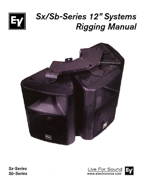
Sx/Sb-Series 12” SystemsRigging ManualSx-SeriesThe Mb KitsElectro-Voice® manufactures three accessories to make the sus-pension of Sx/Sb-Series enclosures safe, easy and cost-effective: the Mb100 Eyebolt Attachment Kit, the Mb200 Installation Kit and the Mb300 Horizontal Array Kit. This instruction sheet gives a brief overview of how each of these suspension kits could be used so the correct kit can be selected. In addition, each of the suspension kits includes a separate instruction sheet with complete dimensions and full details for use.Suspending Sx/Sb-Series EnclosuresThe molded enclosures used in Sx/Sb-Series are lightweight and structurally sound. Each enclosure has four metric M8 x 1.25 metal inserts molded into the enclosure to aid in suspension and aiming. A single insert, correctly used, will safely suspend the weight of one enclosure with a safety factor in excess of 5 to 1. It will not support additional weight with a sufficient safety factor for overhead lifting. If multiple Sx/Sb-Series enclosures are suspended, Mb200 Installation Kits must be used to support and aim each enclosure.Mb100 Eyebolt Attachment KitThe Mb100 Eyebolt Attachment Kit is intended for very simple instal-lations only, to suspend an individual Sx/Sb-Series loudspeaker in a near-vertical orientation (see Figure 1). A second, redundant insert point is provided in the top of the enclosure so a supplementaryindependent means of suspension can be attached when regulations specify. The enclosure can be positioned to angle downward slightly through the use of the pull-up point at the back of the enclosure.Note that two top suspension cables should be used at all times to provide needed stability to the installation (see Figure 1).Do not suspend Sx/Sb-Series enclosures face down from the ceiling using the Mb100 Eyebolt Attachment Kit. The M8 eyebolts are not rated for lifting loads at 90°, and such a configuration makes stabilization of the enclosure difficult. Instead, use the Mb200 Installation Kit for this and most other situations (see the Mb200 Installation Kit section).Mb200 Installation KitThe Mb200 Installation Kit provides a cost-effective and safe means of attaching Sx/Sb-Series loudspeakers to walls or suspending them overhead (see Figure 2). The kit contains a large, reinforced-steel bracket with a selection of thru-holes which allow the bracket to be mounted to different surfaces in a range of orientations. This kit is rec-ommended for most installations, and is essential when arraying Sx/Sb-Series loudspeakers.The Mb200 U-bracket extends from top to bottom of the Sx/Sb-Se-ries loudspeaker and attaches at both ends. This securely “captures” the enclosure, allowing further loudspeaker systems to be added without increasing the stress on the first enclosure. It also allows the loudspeaker to be aimed in the desired direction and locked in place. For even greater flexibility, three-hole-pattern groups compatible with the OmniMount® 60.0 (originally Series 100)1 support system have also been incorporated into the Mb200 Installation Kit's U-bracket (see Figure 2B, reference A).Vertical arrays can be constructed by "daisy chaining" Mb200's to-gether (see Figure 3). To achieve a slight downward angle, attach an additional cable to the lower Mb200 and use this cable to pull up the array, securing the cable at the desired angle and position.No more than two enclosures should be suspended in a vertical array in this manner. If a taller array is required, you should provide a means of independent suspension for the remaining enclosures.Again, note the use of two top suspension cables (see Figure 3) which provide stability and should be used at all times.Horizontal ArrayNumber of Enclosuresin Array:Number of Kits Required Mb200Mb3002213324435546(Complete Circle)66Each Mb300 Horizontal Array Kit consists of two connector brackets (one top, one bottom) plus the hardware required to join these brack-ets to the U-brackets from two Mb200 Installation Kits. This combina-tion of one Mb300 Horizontal Array Kit plus two Mb200 Installation Kits forms a solid frame suitable for suspending two Sx/Sb-Series loudspeakers in a horizontal array (see Figure 4). Holes are provided in the Mb300 brackets for attaching cables for suspension.Two mounting angles, 50° and 60°, are possible using the Mb300 Horizontal Array Kit. Use of the 50° angle results in a tight array with speaker sides touching (see Figure 5); use of the wider orientation results in improved coverage for multiple loudspeakers and allows construction of a complete, 360° array (see Figure 6 for diagram of one half of a 360° array). A vertical array can also be constructed using the Mb300 Horizontal Array Kit, but relatively few aiming angles are available.1. OmniMount® is a registered trademark of OmniMount Systems, Inc.For more information, visit Mb300 Horizontal Array KitThe Mb300 Horizontal Array Kit must be used in conjunction with the Mb200 Installation Kit. Select the required number of kits from the chart below:Figure 1:Overhead Suspension Using the Mb100 Eyebolt Attachment Kit Figure 2a:Wall Mounting Using the Mb200 Installation KitFigure 2b:Vertical Overhead Suspension Using theMb200 Installation KitFigure 2c:Horizontal Overhead Suspension Using the Mb200 Installation KitFigure 3:Vertical Array Using the Mb200 Installation Kit12000 Portland Avenue South, Burnsville, MN 55337Phone: 952/884-4051, Fax: 952/884-0043Electro-Voice ®Figure 4a:Brackets from One Mb300 Horizontal Array Kit and TwoMb200 Installation Kits, Positioned for AssemblyFigure 4b:Assembled Horizontal Array Mounting Frame Consisting ofOne Mb300 Horizontal Array Kit and Two Mb200Installation KitsFigure 4c:Two Enclosure Horizontal Array Using the Mb300Horizontal Array Kit Figure 4d:Orientation for Full Circle (360°) Array Using the Mb300Horizontal Array Kit (Partial Array Shown)U.S.A. and Canada only. For customer orders, contact Customer Service at:800/392-3497 Fax: 800/955-6831Europe, Africa, and Middle East only. For customer orders, contact Customer Service at:+ 49 9421-706 0 Fax: + 49 9421-706 265Other Internatonal locations. For customer orders, Contact Customer Service at:+ 1 952 884-4051 Fax: + 1 952 887-9212。
TSB12LV31中文资料

IMPORTANT NOTICETexas Instruments and its subsidiaries (TI) reserve the right to make changes to their products or to discontinue any product or service without notice, and advise customers to obtain the latest version of relevant information to verify, before placing orders, that information being relied on is current and complete. All products are sold subject to the terms and conditions of sale supplied at the time of order acknowledgement, including those pertaining to warranty, patent infringement, and limitation of liability.TI warrants performance of its semiconductor products to the specifications applicable at the time of sale in accordance with TI’s standard warranty. Testing and other quality control techniques are utilized to the extent TI deems necessary to support this warranty. Specific testing of all parameters of each device is not necessarily performed, except those mandated by government requirements.CERTAIN APPLICATIONS USING SEMICONDUCTOR PRODUCTS MAY INVOLVE POTENTIAL RISKS OF DEATH, PERSONAL INJURY, OR SEVERE PROPERTY OR ENVIRONMENTAL DAMAGE (“CRITICAL APPLICATIONS”). TI SEMICONDUCTOR PRODUCTS ARE NOT DESIGNED, AUTHORIZED, OR WARRANTED TO BE SUITABLE FOR USE IN LIFE-SUPPORT DEVICES OR SYSTEMS OR OTHER CRITICAL APPLICATIONS. INCLUSION OF TI PRODUCTS IN SUCH APPLICATIONS IS UNDERSTOOD TO BE FULLY AT THE CUSTOMER’S RISK.In order to minimize risks associated with the customer’s applications, adequate design and operating safeguards must be provided by the customer to minimize inherent or procedural hazards.TI assumes no liability for applications assistance or customer product design. TI does not warrant or represent that any license, either express or implied, is granted under any patent right, copyright, mask work right, or other intellectual property right of TI covering or relating to any combination, machine, or process in which such semiconductor products or services might be or are used. TI’s publication of information regarding any third party’s products or services does not constitute TI’s approval, warranty or endorsement thereof.Copyright © 1998, Texas Instruments IncorporatedContentsSection Title Page . . . . . . . . . . . . . . . . . . . . . . . . . . . . . . . . . . . . . . . . . . . . . . . . . . . . . . . . . . . . . . . . . .1Overview1–1 . . . . . . . . . . . . . . . . . . . . . . . . . . . . . . . . . . . . . . . . . . . . . . . . . . . . . . . . . . . .1.1Description1–1. . . . . . . . . . . . . . . . . . . . . . . . . . . . . . . . . . . . . . . . . . . . . . . . . . . . . . . . . . . . . .1.2Features1–1. . . . . . . . . . . . . . . . . . . . . . . . . . . . . . . . . . . . . . . . . . . . . . . . . . . .1.3Related Documents1–2. . . . . . . . . . . . . . . . . . . . . . . . . . . . . . . . . . . . . . . . . . . . . . .1.4Functional Block Diagram1–2. . . . . . . . . . . . . . . . . . . . . . . . . . . . . . . . . . . . . . . . . . . . . . . . . .1.5Terminal Assignments1–3. . . . . . . . . . . . . . . . . . . . . . . . . . . . . . . . . . . . . . . . . . . . . . . . . . . . .1.6Terminal Functions1–4. . . . . . . . . . . . . . . . . . . . . . . . . . . . . . . . . . . . . . . . . . . . . . . . . . . . . . . . . . . . . . .2Architecture2–1. . . . . . . . . . . . . . . . . . . . . . . . . . . . . . . . . . . . . . . . . . . . . . .2.1Functional Block Diagram2–1. . . . . . . . . . . . . . . . . . . . . . . . . . . . . . . . . . . . . . . . . . . . . . . . . . . . . . . . . . .2.1.1FIFO2–1. . . . . . . . . . . . . . . . . . . . . . . . . . . . . . . . . . . . . . . . . .2.1.2Microcontroller Interface2–1. . . . . . . . . . . . . . . . . . . . . . . . . . . . . . . . . . . . . . . . . . . . . . . . . . . . . . .2.1.3Link Core2–9. . . . . . . . . . . . . . . . . . . . . . . . . . . . . . . . . . . . . . . .2.1.4Data Mover (DM) Control2–11. . . . . . . . . . . . . . . . . . . . . . . . . . . . . . . . . . . . . . . . . . . . . . . . . . . . . . . . .3Internal Registers3–1. . . . . . . . . . . . . . . . . . .3.1Memory and Configuration Address Space Register Map3–1. . . . . . . . . . . . . . . . . . . . . . . . . . . . . . .3.1.1TSB12LV31 Configuration Registers3–1. . . . . . . . . . . . . . . . . . . . . . . . . . . . . . . . . . . . . . . .3.2Configuration Register Definitions3–33.2.1Version Register @00h3–3. . . . . . . . . . . . . . . . . . . . . . . . . . . . . . . . . . . . . . . . . . .. . . . . . . . . . . . . . . . . . . . . . . . . . . . . . . . . . . . . . . . . . . . .3.2.2MISC Register @04h3–3. . . . . . . . . . . . . . . . . . . . . . . . . . . . . . . . . . . . . . . . . . .3.2.3Control Register @08h3–33.2.4Interrupt/Interrupt Mask Register @0Ch/10h3–5. . . . . . . . . . . . . . . . . . . . . . . . .. . . . . . . . . . . . . . . . . . . . . . . . . . . . . . . . . . . . . . .3.2.5Cycle Timer Register @14h3–7. . . . . . . . . . . . . . . . . . . . . . . . . . . . . . . . . . . .3.2.6IsoPort Number Register @18h3–7. . . . . . . . . . . . . . . . . . . . . . . . . . . . . . . . . . . . . . .3.2.7Diagnostics Register @20h3–8. . . . . . . . . . . . . . . . . . . . . . . . . . . . . . . . . . . . . . .3.2.8Phy Access Register @24h3–9. . . . . . . . . . . . . . . . . . . . . . . . . . . . . . . . . . . . . . .3.2.9ATF Status Register @30h3–103.2.10Bus Reset Register @34h3–11. . . . . . . . . . . . . . . . . . . . . . . . . . . . . . . . . . . . . . .. . . . . . . . . . . . . . . . . . . . . . . . . . . . . . . . . . . .3.2.11Self-ID Check Register @38h3–11. . . . . . . . . . . . . . . . . . . . . . . . . . . . . . . . . . . . . .3.2.12GRF Status Register @3Ch3–12. . . . . . . . . . . . . . . . . . . . . . . . . . . . . . . . . . . . . . .3.2.13FIFO State Register @50h3–12. . . . . . . . . . . . . . . . . . . . . . . . . . . . . . .3.2.14Isochronous Control Register @54h3–13. . . . . . . . . . . . . . . . . . . . . . . . . . . . . . . .3.2.15Isochronous Mode Register @58h3–133.2.16Isochronous Header Register @5Ch3–13. . . . . . . . . . . . . . . . . . . . . . . . . . . . . .iiiContents (continued)Section Title Page . . . . . . . . . . . . . . . . . . . . . . . . . . . . . . . . . . . . . . . . . . . . . . . . . . . . . . . . . . . . . .4FIFO Access4–1. . . . . . . . . . . . . . . . . . . . . . . . . . . . . . . . . . . . . . . . . . . . . . . . . . . . . . . . . .4.1FIFO Access4–14.1.1ATF Access4–1. . . . . . . . . . . . . . . . . . . . . . . . . . . . . . . . . . . . . . . . . . . . . . . . . . . . .. . . . . . . . . . . . . . . . . . . . . . . . . . . . . . . . . . . . .4.1.2General-Receive-FIFO (GRF)4–2. . . . . . . . . . . . . . . . . . . . . . . . . . . . . . . . . . . . . . . . . . . . . . . . . .5TSB12LV31 Data Formats5–1. . . . . . . . . . . . . . . . . . . . . . . . .5.1Asynchronous Transmit (Host Bus to TSB12LV31)5–1. . . . . . . . . . . . . . . . . . . . . . . . . . . . . . . . . . . . . . . . . . . . . . . .5.1.1Quadlet Transmit5–1. . . . . . . . . . . . . . . . . . . . . . . . . . . . . . . . . . . . . . . . . . . . . . . . . .5.1.2Block Transmit5–25.1.3Quadlet Receive5–3. . . . . . . . . . . . . . . . . . . . . . . . . . . . . . . . . . . . . . . . . . . . . . . . .. . . . . . . . . . . . . . . . . . . . . . . . . . . . . . . . . . . . . . . . . . . . . . . . . . .5.1.4Block Receive5–4. . . . . . . . . . . . . . . . . . . . . . . . . . .5.2Isochronous Transmit (Host Bus to TSB12LV31)5–6. . . . . . . . . . . . . . . . . . . . . . . . . . .5.3Isochronous Receive (TSB12LV31 to Host Bus)5–6. . . . . . . . . . . . . . . . . . . . . . . . . . . . . . . . . . . . . . . . . . . . . . . . . . . . . . . . . . . . . . . .5.4Snoop5–7. . . . . . . . . . . . . . . . . . . . . . . . . . . . . . . . . . . . . . . . . . . . . . . . . . . . . . . . . . . .5.5CycleMark5–85.6Phy Configuration5–8. . . . . . . . . . . . . . . . . . . . . . . . . . . . . . . . . . . . . . . . . . . . . . . . . . . . . .. . . . . . . . . . . . . . . . . . . . . . . . . . . . . . . . . . . . . . . . . . . . . . . . .5.7Receive Self-ID Packet5–9. . . . . . . . . . . . . . . . . . . . . . . . . . . . . . . . . . . . . . . . . . . . . . . . . .6Electrical Characteristics6–1. . . . . . . . . . . . . .6.1Absolute Maximum Ratings Over Free-Air Temperature Range6–1. . . . . . . . . . . . . . . . . . . . . . . . . . . . . . . . . . . . .6.2Recommended Operating Conditions6–26.3Electrical Characteristics Over Recommended Ranges of Supply Voltage and. . . . . . . . . . . . . . . . . . . . . . . . . . . . . . . . . . .Operating Free-Air Temperature Range6–26.4Microcontroller Write Switching Characteristics Over Operating Free-Air. . . . . . . . . . . . . . . . . . . . . . . . . . . . . . . . . . . . . . . . . . . . . . . . . . . .Temperature Range6–36.5Microcontroller Read Switching Characteristics Over Operating Free-Air. . . . . . . . . . . . . . . . . . . . . . . . . . . . . . . . . . . . . . . . . . . . . . . . . . . .Temperature Range6–46.6IsoPort Phase 1, 2, and 3 Switching Characteristics Over Operating Free-Air. . . . . . . . . . . . . . . . . . . . . . . . . . . . . . . . . . . . . . . . . . . . . . . . . . . .Temperature Range6–56.7IsoPort Receive Switching Characteristics Over Operating Free-AirTemperature Range6–7. . . . . . . . . . . . . . . . . . . . . . . . . . . . . . . . . . . . . . . . . . . . . . . . . . . .6.8Link Read/Write Switching Characteristics Over Operating Free-Air. . . . . . . . . . . . . . . . . . . . . . . . . . . . . . . . . . . . . . . . . . . . . . . . . . .Temperature Range6–106.9Output Signals Synchronous with ISOCK Switching Characteristics Over Operating. . . . . . . . . . . . . . . . . . . . . . . . . . . . . . . . . . . . . . . . . . .Range6–11 TemperatureFree-Air. . . . . . . . . . . . . . . . . . . . . . . . . . . . . . . . . . . . . . . . . . . . . . . . . . . .7Mechanical Information7–1ivList of IllustrationsFigure Title Page. . . . . . . . . . . . . . . . . . . . . . . . . . . . . . . . . . . . . . . .1–1TSB12LV31 Functional Block Diagram1–2. . . . . . . . . . . . . . . . . . . . . . . . . . . . . . . . . . . . . . . . . . . . . . . . . . . . . .1–2Terminal Assignments1–3. . . . . . . . . . . . . . . . . . . . . . . . . . . . . . . . . . . . . . . .2–1TSB12LV31 Functional Block Diagram2–1. . . . . . . . . . . . . . . . . . . . . . . . . .2–2Typical Handshake Doublet-Mode Timing Waveforms2–2. . . . . . . . . . . . . . . . . . . . . . . . . . . . .2–3Typical Handshake Byte-Mode Timing Waveforms2–3. . . . . . . . . . . . . . . . . . . . . . . . . . . . . . . . . . . . . . . . . . . . . .2–4Pulse Mode Timing Waveforms2–3. . . . . . . . . . . . . . . . . . . . .2–5Timing Waveforms for 16-Bit Pulse Mode with Fixed Timing2–5. . . . . . . . . . . . . . . . . . . . . .2–6Timing Waveforms for 8-Bit Pulse Mode with Fixed Timing2–7. . . . . . . . . . . . . . . . . . . . . . . . . . . . . . . . . . .2–7Microcontroller Byte Stack Operation (Write)2–8 2–8Microcontroller Byte UnStack Operation (Read)2–9. . . . . . . . . . . . . . . . . . . . . . . . . . . . . . . .. . . . . . . . . . . . . . . . . . . . . . . . . . . . . . . . . . . . . . . . . . . . . . . . . . . . .2–9Link Core Components2–9. . . . . . . . . . . . . . . . . . . . . . . .2–10Isochronous DM Flow Control (TSB12LV31 Transmit)2–12 2–11Isochronous Transmit Data Path2–13. . . . . . . . . . . . . . . . . . . . . . . . . . . . . . . . . . . . . . . . . . .. . . . . . . . . . . . . . . . . . . . . . . . . . . . . . . . . . . . . . . . . . .3–1Configuration Register (CFR) Map3–2. . . . . . . . . . . . . . . . . . . . . . . . . . . . .4–1TSB12LV31 Controller-FIFO-Access Address Map4–1. . . . . . . . . . . . . . . . . . . . . . . . . . . . . . . . . . . . . . . . . . . . . . . . . . .5–1Quadlet-Transmit Format5–1. . . . . . . . . . . . . . . . . . . . . . . . . . . . . . . . . . . . . . . . . . . . . . . . . . . . .5–2Block-Transmit Format5–2. . . . . . . . . . . . . . . . . . . . . . . . . . . . . . . . . . . . . . . . . . . . . . . . . . . .5–3Quadlet-Receive Format5–3. . . . . . . . . . . . . . . . . . . . . . . . . . . . . . . . . . . . . . . . . . . . . . . . . . . . . .5–4Block-Receive Format5–4. . . . . . . . . . . . . . . . . . . . . . . . . . . . . . . . . . . . . . . . . . . . . . .5–5Isochronous-Transmit Format5–6. . . . . . . . . . . . . . . . . . . . . . . . . . . . . . . . . . . . . . . . . . . . . . . .5–6Isochronous-Receive Format5–6 . . . . . . . . . . . . . . . . . . . . . . . . . . . . . . . . . . . . . . . . . . . . . . . . . . . . . . . . . . . . .5–7Snoop Format5–7. . . . . . . . . . . . . . . . . . . . . . . . . . . . . . . . . . . . . . . . . . . . . . . . . . . . . . . . .5–8CycleMark Format5–8. . . . . . . . . . . . . . . . . . . . . . . . . . . . . . . . . . . . . . . . . . . . . . . . . . .5–9Phy Configuration Format5–8 5–10Receive Self-ID Format5–9. . . . . . . . . . . . . . . . . . . . . . . . . . . . . . . . . . . . . . . . . . . . . . . . . . . .. . . . . . . . . . . . . . . . . . . . . . . . . . . . . . . . . . . . . . . . . . . . .5–11Phy Self-ID Packet #0 Format5–10. . . . . . . . . . . . . . . . . . . . .5–12Phy Self-ID Packet #1, Packet #2, and Packet #3 Format5–10 6–1Microcontroller Write-Operation Timing Waveforms6–3. . . . . . . . . . . . . . . . . . . . . . . . . . . . .. . . . . . . . . . . . . . . . . . . . . . . . . . . . .6–2Microcontroller Read-Operation Timing Waveforms6–4. . . . . . . . . . . . . . . . . . . . . . . .6–3IsoPort Phase 1 (Four-Byte Preread) Timing Waveforms6–5. . . . . . . . . . . . .6–4IsoPort Phase 2 (Data Transmit to End of Packet) Timing Waveforms6–6. . . . . . . . . . . . . . . . . . . . . . . . . . . . .6–5IsoPort Phase 3 (End of Block) Timing Waveforms6–6. . . . . . . . . . . . . . . . . . . . . . . . . . . . . . . . . . . . . . . . . .6–6IsoPort Receive Timing Waveforms6–7. . . . . . . . . . . . . . . . . . . . . . . . . . . .6–7Isochronous Receive of One Quadlet at 200 Mbits/s6–8. . . . . . . . . . . . . . .6–8Isochronous-Receive Four Quadlets with Data Error at 200 Mbits/s6–9. . . . . . . . . . . . . . . . . . . . . . . . . . . . . . . . . . . . . . . . . . . . . . . . . . . . .6–9Link Read Waveforms6–10. . . . . . . . . . . . . . . . . . . . . . . . . . . . . . . . . . . . . . . . . . . . . . . . . . . .6–10Link Write Waveforms6–10. . . . . . . . . . . . . . . . . . . . . . . . . . . . . . . . . . . .6–11Synchronous ISOCK Output Waveforms6–11vList of TablesTable Title Page. . . . . . . . . . . . . . . . . . . . . . . . . . . . . . . . . . . . . . . . . . . . . . . . . . . . . . . . .1–1Terminal Functions1–4. . . . . . . . . . . . . . . . . . . . . . . . . . . . . . . . . . . . . . . . . . . . .1–2STAT0 and STAT1 Programming1–7. . . . . . . . . . . . . . . . . . . . . . . . . . . . . . . . . . . . . .2–1Isochronous Transmit Packet Structure2–13 3–1Memory and Configuration Address Space Map3–1. . . . . . . . . . . . . . . . . . . . . . . . . . . . . . .. . . . . . . . . . . . . . . . . . . . . . . . . . . . . . . . . . . . . .3–2MISC Register Field Descriptions @04h3–3. . . . . . . . . . . . . . . . . . . . . . . . . . . . . . . . . . . . .3–3Control Register Field Descriptions @08h3–3. . . . . . . . . . . . . . . . . .3–4Interrupt/Interrupt Mask Register Field Descriptions @0Ch/10h3–5. . . . . . . . . . . . . . . . . . . . . . . . . . . . . . . . .3–5Cycle-Timer Register Field Descriptions @14h3–7. . . . . . . . . . . . . . . . . . . . . . . . . . . . .3–6IsoPort Number Register Field Descriptions @18h3–7. . . . . . . . . . . . . . . . . . . . . . . . . . . . . . . . .3–7Diagnostics Register Field Descriptions @20h3–8. . . . . . . . . . . . . . . . . . . . . . . . . . . . . . . . . . . . . . . . . .3–8Recommended Range for XtendClk3–9. . . . . . . . . . . . . . . . . . . . . . . . . . . . . . . . . . . . . . . . . . . . . . . . .3–9Phy Access Register @24h3–9. . . . . . . . . . . . . . . . . . . . . . . . . . . . . . . . . . . . . . . . . . . . . . . .3–10ATF Status Register @30h3–10. . . . . . . . . . . . . . . . . . . . . . . . . . . . . . . . . . . . . . . . . . . . . . . . .3–11Bus Reset Register @34h3–11. . . . . . . . . . . . . . . . . . . . . . . . . . . . . . . . . . . . . . . . . . . . . .3–12Self-ID Check Register@38h3–11. . . . . . . . . . . . . . . . . . . . . . . . . . . . . . . . . . . . . . . . . . . . . . .3–13GRF Status Register @3Ch3–12. . . . . . . . . . . . . . . . . . . . . . . . . . . . . . . . . . . . . . . . . . . . . . . .3–14FIFO State Register @50h3–12. . . . . . . . . . . . . . . . . . . . . . . . . . . . . . . . . . . . . . . .3–15Isochronous Control Register @54h3–13 3–16Isochronous Mode Register @58h3–13. . . . . . . . . . . . . . . . . . . . . . . . . . . . . . . . . . . . . . . . .. . . . . . . . . . . . . . . . . . . . . . . . . . . . . . . . . . . . . . . . .3–17Isochronous Mode Register@5Ch3–13 5–1Quadlet-Transmit Format Functions5–1. . . . . . . . . . . . . . . . . . . . . . . . . . . . . . . . . . . . . . . . . .. . . . . . . . . . . . . . . . . . . . . . . . . . . . . . . . . . . . . . . . . . . .5–2Block-Transmit Format Functions5–2. . . . . . . . . . . . . . . . . . . . . . . . . . . . . . . . . . . . . . . . . . .5–3Quadlet-Receive Format Functions5–3. . . . . . . . . . . . . . . . . . . . . . . . . . . . . . . . . . . . . . . . . . . . .5–4Block-Receive Format Functions5–5. . . . . . . . . . . . . . . . . . . . . . . . . . . . . . . . . . . . . . . . . . . . .5–5Isochronous-Transmit Functions5–6. . . . . . . . . . . . . . . . . . . . . . . . . . . . . . . . . . . . . . . . . . . . . .5–6Isochronous-Receive Functions5–7 . . . . . . . . . . . . . . . . . . . . . . . . . . . . . . . . . . . . . . . . . . . . . . . . . . . . . . . . . . .5–7Snoop Functions5–7. . . . . . . . . . . . . . . . . . . . . . . . . . . . . . . . . . . . . . . . . . . . . . . . . . . . . . . .5–8CycleMark Function5–8. . . . . . . . . . . . . . . . . . . . . . . . . . . . . . . . . . . . . . . . . . . . . . . .5–9Phy Configuration Functions5–8. . . . . . . . . . . . . . . . . . . . . . . . . . . . . . . . . . . . . . . . . . . . . . . . . .5–10Receive Self-ID Function5–9. . . . . . . . . . . . . . . . . . . . . . . . . . . . . . . . . . .5–11GRF Contents With Three Nodes on a Bus5–9. . . . . . . . . . . . . . . . . . . . . . . . . . . . . . . . . . . . . . . . . . . . . . . . . . . .5–12Phy Self-ID Functions5–10viList of Tables (continued)Table Title Page. . . . . . . . . . . . . . . . . . . . . . . . . . . . . . . . . . . . . . . . . . . . . . . .6–1Microcontroller Write Timing6–3. . . . . . . . . . . . . . . . . . . . . . . . . . . . . . . . . . . . . . . . . . . . . . . . .6–2Microcontroller Read Timing6–4. . . . . . . . . . . . . . . . . . . . . . . . . . . . . . . . . . . . . . . . . . . .6–3IsoPort Timing Phases 1, 2, and 36–5. . . . . . . . . . . . . . . . . . . . . . . . . . . . . . . . . . . . . . . . . . . . . . . . . . . . .6–4IsoPort Receive Timing6–7. . . . . . . . . . . . . . . . . . . . . . . . . . . . . . . . . . . . . . . . . . . . . . . . . . . .6–5Link Read/Write Timing6–10 6–6Synchronous ISOCK Output Timing6–11. . . . . . . . . . . . . . . . . . . . . . . . . . . . . . . . . . . . . . . . .viiviii1Overview1.1DescriptionThe TSB12LV31 performs bidirectional asynchronous/isochronous data transfers to and from an IEEE 1394-1995 serial bus physical layer (phy) device. The TSB12LV31 is tailored and optimized for use as a peripheral link-layer controller (LLC). TSB12LV31 asynchronous and isochronous operations are summarized as follows:TSB12LV31 asynchronous transmit:From asynchronous transmit FIFO (ATF)TSB12LV31 asynchronous receive:To general receive FIFO (GRF)TSB12LV31 isochronous transmit:From 8-bit IsoPortTSB12LV31 isochronous receive:To 8 bit IsoPort,To GRF, orTo 8-bit IsoPort and To GRFThis document is not intended to serve as a tutorial on the 1394; users should refer to the IEEE 1394-1995 standard for more detailed information.1.2FeaturesThe TSB12LV31 supports the following features:•Provisions of IEEE 1394-1995 Standard for High-Performance Serial Bus (1394)†•Fully Interoperable with FireWire™ Implementation of 1394•Compatible with Texas Instruments TSB11LV01 and TSB21LV03 Physical Layer Controllers (Phys)•Single 3.3-V supply operation with 5-V Tolerant Capabilities using 5-V Bias Terminals•High-performance 100-Pin PZ (S–PQFP–G100) package.•Programmable Microcontroller Interface with 8-Bit or 16-Bit Data Bus, Three Modes of Operation, and Clock Frequency to 50 Mhz•50-quadlet (200-Byte) FIFO Accessed Through Microcontroller Interface Supports Asynchronous and Isochronous Operations•Programmable FIFO Size For Asynchronous Transmit FIFO and General-Receive FIFO•Single-Channel Support for Isochronous Transmit from Unbuffered 8-Bit Isochronous Port (IsoPort)•Isochronous Receive to FIFO or to Unbuffered 8-Bit IsoPort•Isochronous Header Synchronous-Bit Detection on Receive•Automatically Reports IRM NODE_ID and Verifies Automatic 1394 Self-ID•Transfer Rates of 100 Mbits/s and 200 Mbits/s•Asynchronous Packet Reception to Internal FIFO (Accessed Through the Microcontroller Interface)•Asynchronous Packet Transmission from Internal FIFO (Accessed Through the Microcontroller Interface)•Generation of External Microcontroller Clock from SCLK (SCLK/4)•Generation of 32-Bit Cyclic Redundancy Check (CRC) for Transmission of 1394 Packets•32-Bit CRC Checking on Reception of 1394 Packets†Implements technology covered by one or more patents of Apple Computer, Incorporated and SGS Thomson, Limited. FireWire is a trademark of Apple Computer, Incorporated.1–1元器件交易网2.1.2.5Microcontroller 8-Bit Pulse Mode with Fixed TimingFigure 2–6 shows a pulse with a fixed timing sequence in byte (8-bit) mode for a write operation withXtendClk set to 11h. In this example, the quadlet value 00 00 08 02h is being written to the configurationregister 54h. Note that MD0 – MD7 is not used in this mode (see Figure 6–1 and Figure 6–2).2–6元器件交易网2.1.3.1Physical InterfaceThe physical (phy) interface provides phy-level services to the transmitter and receiver. This includesgaining access to the serial bus, sending packets, receiving packets, and sending and receivingacknowledge packets.The phy interface module also interfaces to the phy chip and conforms to the phy-LLC interface specificationdescribed in Annex J of the IEEE-1394 standard.2.1.3.2TransmitterThe transmitter retrieves data from either the asynchronous transmit FIFO (ATF) or the IsoPort and createscorrectly formatted serial-bus packets to be transmitted through the phy interface. When data is present atthe ATF interface to the transmitter, the TSB12LV31 phy interface arbitrates for the serial bus and sends apacket. When data is present at the IsoPort, the TSB12LV31 arbitrates for the serial bus during the nextisochronous cycle. The transmitter autonomously sends the cycle-start packets when the chip is a cyclemaster.2.1.3.3ReceiverThe receiver takes incoming data from the phy interface and determines if the incoming data is addressedto this node. When the incoming packet is addressed to this node, the CRC of the packet is checked. If theheader CRC is good, the header is confirmed in the general-receive FIFO (GRF). For block and isochronouspackets, the remainder of the packet is confirmed one quadlet at a time. The receiver places a status quadletin the GRF after the last quadlet of the packet is confirmed in the GRF. The status quadlet contains the errorcode for the packet. The error code is the acknowledge code that is sent for that packet. For broadcastpackets that do not need acknowledge packets, the error code is the acknowledge code that would havebeen sent. This acknowledge code tells the transaction layer whether or not the data CRC is good or bad.When the header CRC is bad, the header is flushed and the rest of the packet is ignored.When a cycle-start message is received, it is detected and the cycle-start message data is sent to the cycletimer. The cycle-start messages are not placed in the GRF like other quadlet packets. At the end of anisochronous cycle and if the cycle mark enable (CyMrkEn) bit of the control register is set, the receiverinserts a cycle-mark packet in the GRF to indicate the end of the isochronous cycle.2.1.3.4Cycle TimerThe cycle timer is used by nodes that support isochronous data transfer. The cycle timer is a 32-bitcycle-timer register. Each node with isochronous data-transfer capability has a cycle-timer register asdefined in 1394. In the TSB12LV31, the cycle-timer register is implemented in the cycle timer and is locatedin the IEEE-1212 initial register space at location 200h and can also be accessed through the local bus ataddress 14h. The low-order 12 bits of the timer are a modulo 3072 counter, which increments once every24.576-MHz clock periods (or 40.69 ns). The next 13 higher-order bits are a count of 8,000-Hz (or 125-µs)cycles, and the highest 7 bits count seconds.The cycle timer contains the cycle-timer register. The cycle-timer register consists of three fields: cycleoffset, cycle count, and seconds count. The cycle timer has two possible sources. First, when the cyclesource (CySrc) bit in the configuration register is set, then the CYCLEIN input causes the cycle count fieldto increment for each positive transition of the CYCLEIN input (8 kHz) and the cycle offset resets to all zeros.CYCLEIN should only be the source when the node is the cycle master. When the cycle-count fieldincrements, CYCLEOUT is generated. The timer can also be disabled using the cycle-timer-enable bit inthe control register.The second cycle-source option is when the CySrc bit is cleared. In this state, the cycle-offset field of thecycle-timer register is incremented by the internal 24.576-MHz clock. The cycle timer is updated by thereception of the cycle-start packet for the noncycle master nodes. Each time the cycle-offset field rolls over,the cycle-count field is incremented and the CYCLEOUT signal is generated. The cycle-offset field in thecycle-start packet is used by the cycle-master node to keep all nodes in phase and running with a nominalisochronous cycle of 125 µs.2–10元器件交易网CYCLEOUT indicates to the cyclemaster node that it is time to send a cycle-start packet. And, onnoncyclemaster nodes, CYCLEOUT indicates that it is time to expect a cycle-start packet. The cycle-startbit is set when the cycle-start packet is sent from the cyclemaster node or received by a noncyclemasternode.2.1.3.5Cycle MonitorThe cycle monitor is only used by nodes that support isochronous data transfer. The cycle monitor observeschip activity and handles scheduling of isochronous activity. When a cycle-start message is received or sent,the cycle monitor sets the cycle-started interrupt bit. It also detects missing cycle-start packets and sets thecycle-lost interrupt bit when this occurs. When the isochronous cycle is complete, the cycle monitor sets thecycle-done-interrupt bit. The cycle monitor instructs the transmitter to send a cycle-start message when thecyclemaster bit is set in the control register.2.1.3.6 Cyclic Redundancy Check (CRC)The CRC module generates a 32-bit CRC for error detection. This is done for both the header and the data.The CRC module generates the header and data CRC for transmitting packets and checks the header anddata CRC for received packets (see the IEEE-1394 standard for details on the generation of the CRC†).2.1.4Data Mover (DM) ControlThe following sections describe the transmit and receive data mover control.2.1.4.1Isochronous Transmit DMIn order to successfully transmit an isochronous packet, the following must occur:1.The external source for the isochronous data must be ready to begin transmitting one byte (at200 Mbits/s operation) of isochronous data per ISOCK clock cycle.2.The transmitter must be enabled by setting the TxEn bit (see subsection3.2.3).3.The isochronous mode must be set to transmit by setting the isomode bits to 00 (seesubsection 3.2.15). This is the default value of the isomode bits.4.The isodmen bit must be set (see subsection 3.2.15).5.CFR must be programmed for the isochronous sequence that is about to start (seesubsection 3.2.15 and subsection 3.2.16).For example:When CFR= 00 00 18 03h, this indicates that three quadlets make up a packet and two packetsdefine a block of data (see subsection 3.2.15).When CFR = 00 0C 01 18h, this indicates that the channel addressed is channel 1, the Tag field isnot used, the speed to be used is 200 Mbits/s, and the Sync field is set (see subsection 3.2.16 andsubsection 3.2.3).The isochronous header is defined by the Iso Header register (see subsection 3.2.16) and isinserted into the isochronous stream. The CRC is generated and transmitted along with theheader and the data.6.IDATARDY is asserted high to start the isochronous transmit sequence.The isochronous transmit DM reads digital data from the IsoPort (ISOD0 – ISOD7) and passes it to the 1394isochronous transmit interface in accordance with Figure 2–10. The isochronous data path is shown inFigure 2–11.†This is the same CRC used by the IEEE802 LANs and the X3T9.5 FDDI.2–11。
Elation DM-2512R 用户手册说明书

24-004-1291Rev 1.2DM-2512RIntroductionThank you for purchasing the Elation DM-2512R.Please read the instructions in this manualcarefully and thoroughly before attempting to operate this unit.These instructions contain important information regarding safety during use and maintenance.Please fill out and return the enclosed warranty card to validate your purchase.USER MANUALCustomer ServiceElation provides a toll free customer support line,to provide set up help and to answer any question should you encounter problems during your set up or initial operation.You may also visit us on the web at for any comments or suggestions.All returned service items whether under warranty or not,must be freight pre-paid and accompany a Return Authorization (RA)number.The RA number must be clearly written on the outside of the returnpackage.Items returned without a RA number clearly marked on the outside of the package will be refused and returned at customer’s expense.You may obtain a RA number by contacting customer service.A brief description of the problem as well as the RA number must be written down on a piece of paper and included in the shipping container.If the unit is under warranty,you must also provide a copy of your proof of purchase invoice.Customer Service hours are Monday through Friday 8:00a.m.-5:00p.m.Pacific Standard Toll Free:(866)245-6726Phone:(323)582-3322Fax:(323)832-9142Information:Sales:Support:Forum:****************************************************************************/eveThis manual is Copyright ©2008Elation Professional.All rights reserved.No part of the manual included with this product can be reproduced or transmitted in any form,by any means,for any purpose without prior written authorized permission.Information contained in this manual is subject to change at any time and without notice.Please contact Elation Customer Service or visit for the latest manual revisions.2-Year Limited WarrantyElation®hereby warrants,to the original purchaser,Elation Professional®products to be free of manufacturing defects in material and workmanship for a period of2Years(730days)on all internal parts and components and1Year(365days)on labor from the date of purchase.This warranty shallbe valid only if the product is purchased within the United States of America,including possessionsand territories.It is the owner’s responsibility to establish the date and place of purchase byacceptable evidence,at the time service is sought.For warranty service,send the product only to the Elation factory.All shipping charges must be prepaid. If the requested repairs or service(including parts replacement)are within the terms of thiswarranty,Elation will pay return shipping charges only to a designated point within the United States except Hawaii or Alaska.If the entire instrument is sent,it must be shipped in its original package.No accessories should be shipped with the product.If any accessories are shipped with the product, Elation shall have no liability whatsoever for loss of or damage to any such accessories,nor for thesafe return thereof.This warranty is void if:•The serial number has been altered or removed•The product is modified in any manner which Elation concludes,after inspection,affects thereliability of the product•The product has been repaired or serviced by anyone other than the Elation factory unlessprior written authorization was issued to purchaser by Elation•The product is damaged because not properly maintained as set forth in the instructionManualThis is not a service contract,and this warranty does not include maintenance,cleaning or periodic check-up.During the period specified above,Elation will replace defective parts at its expense,andwill absorb all expenses for warranty service and repair labor by reason of defects in material or workmanship.The sole responsibility of Elation under this warranty shall be limited to the repair ofthe product,or replacement thereof,including parts,at the sole discretion of Elation.All products covered by this warranty were manufactured after January1,1990,and bear identifying marks to that effect.Elation reserves the right to make changes in design and/or improvements upon its products withoutany obligation to include these changes in any products theretofore manufactured.No warranty,whether expressed or implied,is given or made with respect to any accessory supplied with products described above.Except to the extent prohibited by applicable law,all impliedwarranties made by Elation in connection with this product,including warranties of merchantability or fitness,are limited in duration to the warranty period set forth above.And no warranties,whether expressed or implied,including warranties of merchantability or fitness,shall apply to this productafter said period has expired.The consumer’s and or Dealer’s sole remedy shall be such repair or replacement as is expressly provided above;and under no circumstances shall Elation be liable for any loss or damage,direct or consequential,arising out of the use of,or inability to use,this product.This warranty is the only written warranty applicable to Elation Products and supersedes all prior SafetyThe following safety information relates to the DM-2512R.Please read each item carefully to ensure you fully understand them.To prevent the risk of electrical shock,do not open this unit.There are no user serviceable parts inside this unit.Do not attempt any repairs yourself.Doing so will void your manufactures warranty.Should your unit require service,please contact your nearest Elation dealer or Elation Customer Service.To prevent or reduce the risk of electrical shock or fire,do not expose this unit to rain or moisture.Do not remove the plug ground pin or connect to an ungrounded circuit.This unit is not designed for use by persons under the age e only under adult supervision.Turn off the power if not using this unit for a long time.The DM-2512R merges two DMX signal inputs,to one output.Three operation modes can be selected by using the 2dip switch setting.The three operation modes include HTP (Highest Takes Priority)mode,Backup mode and Merge mode.When set to HTP mode,the controller with the highest channel outputsetting will take priority on output.HTP is most commonly used to controller dimmer channels.When set to Backup,a controller that is connected to the B input is on stand and will only take precedence if thecontroller connected to the A input fails.When set to Merge mode,controller signals coming into input A &B will merge to one output.10-position dip switches are available so the starting DMX address channel can be set for the controller that is connected to input B.For example,a Stage Desk 16is connected to input A,we would patch the controller that is connected to input B at channel 17and also set the binary address on the DM-2512R to 17.Description12HTP ModeSet dip-switch 1and 2to "Off"position.This unit will be in HTP (High Take Priority)mode.When two DMX signals are present,the higher DMX values for each channel (1-512)will take precedence.This may allow for some channels of input A controller to be active and other channels from input B controller to be active.12BACKUP ModeSet dip-switch 1to "On"and 2to "Off"position.This unit will be in BACKUP mode.When DMX signal A is present.it will take DMX output priority.When DMX signal A is lost,DMX signal B will takes DMX output priority.12MERGE ModeSet dip-switch 1to "Off"and 2to "On"position.This unit will be in MERGE mode.You can merge DMX signals A and B into a one DMX output.You must set the starting DMX address for the controller that is connected to Input B with dip switches 1-9.DMX Address Setting12345678910onoffDip-switch #(256)(128)(64)(32)(16)(8)(4)(2)(1)DMX Address TableDMX B START CH#DIP-SWITCHSON1141516:::5112,3,41,2,3,45:::1,2,3,4,5,6,7,8,92345678910111213121,231,32,31,2,341,42,41,2,43,41,3,4DIP-SWITCHSONDMX B START CH#Note :If you set dip-switch 1to "On"and the others to "Off"position,all DMX channel output will start with the 1st channel of DMX signal B.Here is a DMX Address setting diagram and a DMX Address table for reference.Operation Guide1.With the DM-2512R’s power switch OFF,connect data cables coming out of your lighting control devicesinto the male,DMX Inputs,of the DM-2512R.Connect data cable to the output of DM-2512and into first DMX device in line.2.HTP Backup Merge12MODESet your desired function mode.When signal is present to inputs A &B,DMX indicator’s should illuminate for both.3.4.Turn the power switch ON.Indicator LED should illuminate.Technical SpecificationsDimension:Weight:DMX Input:DMX output:Power Requirement:DC 9V,1000mA Min.(AC/DC adaptor included)(T )wo 3pin XLR male sockets on the rear panel (One )3pin XLR female sockets on the rear panel Two 3pin XLR female sockets on the front panel Two 3pin XLR male sockets on the front panel 482x 73x 44mm 1.15kg。
高质量表面金属竖道系统产品,适用于照明和电缆支撑说明书

A complete system of top quality, time saving products, designed for surface metal raceways, lighting and cable supports. Innovative designs offer many installation advantages. The surface raceways are U.L. listed and meet the requirements of the National Electrical Code, Article 384.Surface RacewaysOur channel provides structural support in addition to a raceway system.For U.L. wire fill see chart on page 278-279.Cable SupportsA full range of clamps and saddles are offered in porcelain and thermoplastic elastomer. Our Insulclamp ™ cable clamps and porcelain saddles are furnished complete with steel clamps (electro-plated) and Everdur hardware where required.Materials & Finishes *Steel products are made from low carbon steel strips or plates. Porcelain saddles and clamps are made by dry process and white glazed (porcelain dielectric strength is 50 volts per mil). *Unless otherwise noted.Design LoadDesign load data published includes a Safety Factor of 3.0 (Safety Factor = Ratio of ultimate load to the design load).U.L. listed raceway channels:B11, B11KO6 B32, B32KO6B12, B12KO6 B42, B42KO6B22, B22KO6 B52, B52KO6B24, B24KO6 B54, B54KO6B26, B26KO6 B56, B56KO6U.L. File No. E29637In all cases, the snap-in closure strip is required to complete raceway enclosure.MetricMetric dimensions are shown in parentheses. Unless noted, all metric dimensions are in millimeters.Electrical accessories206B-Line series strut systemsEaton(8)(9)(5)(2)(13)(13)(10)(1)(4)(11)(1A) (Not Shown)(3) orElectrical AccessoriesReference page 206 for general fitting and standard finish specifications. U.L. Wire Fill Chart on pages 272 - 273.Electrical accessories207B-Line series strut systemsEatonReference page 206 for general fitting and standard finish specifications. U.L. Wire Fill Chart on pages 272 - 273.Fluorescent fixture hangers208B-Line series strut systemsEatonReference page 206 for general fitting and standard finish specifications. U.L. Wire Fill Chart on pages 272 - 273.Fluorescent fixture hangers209B-Line series strut systemsEatonReference page 206 for general fitting and standard finish specifications. U.L. Wire Fill Chart on pages 272 - 273.Fluorescent fixture hangers210B-Line series strut systemsEatonElectrical accessories(12.7)(7.1)Electrical AccessoriesReference page 206 for general fitting and standard finish specifications. U.L. Wire Fill Chart on pages 272 - 273.B-Line series strut systems Eaton211Reference page 206 for general fitting and standard finish specifications. U.L. Wire Fill Chart on pages 272 - 273.Electrical accessories212Conduit Size B-Line series strut systemsEatonChannel Connection Kit• F or use with B22 & B24 channels.• B ox Dimension: Standard 4" octagon box • Includes:1 pc. B392-22-3/4 End connection (See page 212) 1 pc. 3/4" (20) Insulated chase nipple 1 pc. 3/4" (20) Lock nut • S tandard finish: ZNB718Universal Junction Bob• A ssemble B719 Hubs into B718 square knockouts • D esigned for use with B22 & B24 channel • B 718 Includes:1 pc. Junction box only 1 pc. Cover only2 pcs. #10-20 Round head machine screws • S tandard finish: ZN • W t./C 180 Lbs. (81.6 kg)B719ALUniversal Junction Box Hub• B 719AL Includes:1 pc. B719AL Hub only1 pc. B436S Fixture stud nut 1 pc. 1/4"-20 Square nut2 pcs. #10-24 Self tapping screws 2 pcs. Rubber caps • M aterial: Aluminum • W t./C 25 Lbs. (11.3 kg)B518-1 thru B518-4Universal Junction Box & Hubs• C hannel connection kits as shown in the chart above • I ncludes:1 pc. Junction box with screws 1 pc. Box cover • S tandard finish: ZN Selection GuideSelection GuideElectrical AccessoriesReference page 206 for general fitting and standard finish specifications. U.L. Wire Fill Chart on pages 272 - 273.Junction boxes213B-Line series strut systemsEaton" Reference page 206 for general fitting and standard finish specifications. U.L. Wire Fill Chart on pages 272 - 273.Strut joiners214Note: Strut joiners are not for structural support. A channel support is recommended within 24" (609 mm) of each joint.B-Line series strut systemsEatonReference page 206 for general fitting and standard finish specifications. U.L. Wire Fill Chart on pages 272 - 273.Strut joiners and electrical hardware215B-Line series strut systemsEatonReference page 206 for general fitting and standard finish specifications. U.L. Wire Fill Chart on pages 272 - 273.Electrical hardware & porcelain saddles216B-Line series strut systemsEatonB4060 THRU B4093Insulclamp Cable Clamps (Replaces porcelain clamps)• A ssembly includes:1 Insulclamp ™ & 1 pr. zinc plated pipe straps with Everdur (Silicon Bronze) hardware Electrical AccessoriesReference page 206 for general fitting and standard finish specifications. U.L. Wire Fill Chart on pages 272 - 273.Insulclamp clamps217B-Line series strut systemsEaton。
十二面体扬声器套件用户手册说明书

十二面体扬声器套件由十二面体声源 DS3 和 PA3 功放组成,它能发出声学频谱平坦的声学信号。
注意 进行此类声学测试时一定要佩戴听力保护装置。
标准操作流程1. 用附带的 Speakon 缆线连接 PA3 和十二面体扬声器;2. 接通 PA3 电源并打开开关 => “信号开(Signal ON)”按钮发出红光 (功放静音);3. 将遥控器天线与 PA3 连接;4. 按“信号源(Signal Source)”按钮选择所需的测试信号 => 被选中的信号源 LED 指示灯显示绿色 ;5. 按下“信号开(Signal ON)”按钮,或者遥控器按钮以实现 PA3 的发声 / 静音 => “信号开(Signal ON)”按钮显示绿色 (发声) /红色 (静音);6. 通过“音量调节(Level)”控制声源音量。
信号选择• EQ Pink 内置的经均衡的粉噪声信号,声源发出声学平坦的声音(见第三页,注脚 3)• EQ Line 为外部输入(Line IN)的信号应用内置均衡• Preset 3 内置的未均衡的粉噪声(用于最大化输出功率)• Preset 4 仅放大外部输入的信号,不应用均衡• Preset 5 预留(用于客户定制需求)外部输入(Line IN)使用 XLR 缆线将外部信号发生器与 PA3 功放连接,并 选择信号源为“EQ Line”或“Preset 4”低音炮操作流程用 XLR 缆线将 PA3 功放和有源低音炮连接,按下“启用低音炮(Subwoofer ON)”按钮 => “启用低音炮(Subwoofer ON)”按钮显示绿色功率放大器 PA3十二面体扬声器套件全指向性声源和功放PA3 遥控器十二面体扬声器 DS3LED 提示,除错电源开关电源接口十二面体扬声器输出接口外部信号发生器接口PA3 前面板PA3 技术指标最大短时输出功率 2 x 260 W 输入至 2x 4 Ω (@ 1 % THD)最大持续输出功率1) 2 x 150 W 输入至 2x 4 Ω (内置粉噪声 @ 最大声压级)负载电阻≥ 3 Ω(四脚连接)或 ≥ 8 Ω(两脚连接 / 桥接模式)保护动态压缩,温度,过流,直流,过载截断输出接口4-脚 Speakon(通道 1:1+/1– | 通道 2:2+/2– 或桥接模式:1+/2– )THD典型 0.017 % @ 2 x 120 W 输入至 2 x 4 Ω,1 kHz电平平坦度+0 / –3.3 dB2) @ 20 Hz 至 20 kHz信噪比≥ 86 dB,带宽 22 kHz阻尼因子≥ 120 @ 负载 ≥ 3 Ω 且频率 < 2 kHz电压增益静音 | 音量控制从 –18 dB 至 29.0 dB输入接口电平灵敏度最大输入电平阻抗XLR 平衡0 dBu 特定输出功率输入至 2 x 3 Ω / 2 x 4 Ω(最大增益)20 dBu / ±11 Vp10 kW 平衡低音输出接口增益最大输出电平阻抗截止滤波器XLR 平衡3 dB18 dBu / ±8.72 Vp≤ 600 Ω 平衡120 Hz 巴特沃斯低通滤波器,24 dB/倍频(四阶);辅助高通滤波器在低音炮激活时自动打开信号(可选)EQ Pink3) EQ Line Preset 3 Preset 4 Preset 5内置信号发生器,经均衡的粉噪声(Cf = 3.05)外部信号,经均衡内置信号发生器,未均衡的粉噪声(Cf = 3.4)外部信号,未均衡预留(视客户需求)十二面体声源 DS3 均衡1/3 倍频程1/1 倍频程100 Hz 至 8 kHz 平坦的声学响应100 dB re 1 pW ±3 dB 105 dB re 1 pW ±3 dBLED 提示截断(Clip)保护(Protect)外部输入信号在高温,过流等情况下功放自动关闭输出,具备自动重试功能控制信号开(Signal ON)音量(Level)信号源(Signal Source)启用低音炮(Subwoofer ON)开关信号并带有绿色 / 红色指示灯增益控制选择输出信号开关输出并带有绿色指示灯遥控功放输出开关认证• 欧洲:EMC 2014/30/EU,EN 61326-1:2013,EN 61000-3/4-x,EN 55011+A1:2009,R&TTE 标准 1999/5/EG• 中国:符合无线电管理要求• 日本:ARIB STD-T 67• 美国:FCC.15重量 5 kg (11 lbs)尺寸(长x宽x高)358 x 173 x 245 mm(14.1” x 6.8” x 9.7”)电源100 至 240 VAC,50/60 Hz,850 W保险丝T6.3 A(5 x 20 mm)温度和湿度范围0° 至 +50°C(32° 至 122°F)@ ≤ 90% RH(非冷凝),风扇主动降温配件(自带)• 无线遥控器• 便携包订购信息600 000 506(433 MHz) / 600 000 510(315 MHz,美国)/ 600 000 511(426 MHz,日本)1): 无滤波2): 非均衡,20 kHz 巴特沃斯高通滤波器(24 dB 阻尼因子)3): 非均衡,20 kHz 巴特沃斯高通滤波器(24 dB 阻尼因子)ISO16283-1:2014 标准对连续 1/3 倍频程段间的最小声压级能量差有要求。
StageBar TRI 12 用户手册说明书

StageBar TRI 12CKU-3040USER MANUALTable of ContentsINTRODUCTION (3)SAFETY (3)SERVICE & SUPPORT (3)DISPLAY OPERATION (4)MENU GUIDE (5)DMX VALUES (6)INFRARED REMOTE (IR) CONTROL (9)SETUP & CONNECTIONS (11)TROUBLESHOOTING (11)TECHNICAL INFORMATION (12)Please read these instructions carefully before use. Operating this fixture according to these instructions is important to avoid any possible damage or accidents caused by misuse.IntroductionPackage Contents•StageBar TRI 12•IEC Power Cable•IR Remote•User ManualSafetyCaution! Opening this unit voids warranty. Contact ColorKey for any service requests. Warning! To avoid electrical shock, be sure to disconnect power before any service or when moving or setting up the fixture.Caution! Avoid direct eye exposure with the fixture when on.•This fixture is for indoor use only.•This fixture must be installed a minimum distance of 5 meters (16’4”) away from any lighted objects.•Do not install or operate this fixture near flammable materials.•This device must be installed, operated, and maintained by a qualified professional. •Please check if the voltage is in accordance with the rated power before installing.•Do not operate this fixture if the power cord has been damaged. Turn off fixture and replace with a power cord of similar rating.Service & SupportYour ColorKey product includes a 2-year warranty. For technical support or to register your product, please visit https:///support/You can also reach us by phone Monday thru Friday, 8:30am – 5pm PST at (818) 578-4030.Display OperationMENU: Access the menu/Scroll through menu optionsUP: Scroll through menu selection or increase parameter DOWN: Scroll through menu selection or parameters decrease ENTER: Open/Select the current menu optionMenu GuideMenu Item Values Function A001 1-512 DMX ModeCH03 3/5/7/36 DMX Channel Select CC70 0-99 Auto Run (All-Colors) CP70 0-99 Pulse ChangeDE70 0-99 Fade ChangeAu01 1-14 Auto Pixel Change SP70 0-99 Auto Pixel Speed bE 0 0-3 RGB Sound Pixel Mode R255 0-255 Red DimmerG255 0-255 Green DimmerB255 0-255 Blue DimmerST00 0-99 Strobe Speed AdjustDMX Values3 channels modeChannel Value Function10-255Red dimming (from dark to bright)20-255Green dimming (from dark to bright)30-255Blue dimming (from dark to bright)5 channels modeChannel Value Function10-255Dimmer (from dark to bright)20-255Strobe Speed (from slow to fast)30-255Red dimming (from dark to bright)40-255Green dimming (from dark to bright)50-255Blue dimming (from dark to bright)7 channels modeChannel Value Function1 0-255 Dimmer2 0-255 Strobe speed3 0-13 Dimmer14-26 Auto Run27-39 Pixel Change40-52 Fade Change53-65 Pulse Change66-78 Effect mode 179-91 Effect mode 292-104 Effect mode 3105-117 Effect mode 4118-130 Effect mode 5131-143 Effect mode 6144-156 Effect mode 7157-169 Effect mode 8170-182 Effect mode 9183-195 Effect mode 10196-208 Effect mode 11209-221 Effect mode 12222-234 Effect mode 13235-247 Effect mode 14248-255(CH5-CH7128-255)RGB SoundactiveSound active(CH5-CH7 0-127) Auto-run Soundactive4 0-255 Mode speed5 0-255 Red dimmer6 0-255 Green dimmer7 0-255 Blue dimmer36 channels modeChannel V alue Function1 0-255 R1 dimmer2 0-255 G1 dimmer3 0-255 B1 dimmer4 0-255 R2 dimmer5 0-255 G2 dimmer6 0-255 B2 dimmer…34 0-255 R12 dimmer35 0-255 G12 dimmer36 0-255 B12 dimmerInfrared Remote (IR) ControlTo use the IR remote, simply point the remote at the IR receiver on the lighting fixture. The IR receiver on the StageBar TRI 12 is located front panel with the LED lenses.*DMX512 data transmissions will override programs set by IR Control1.+/- Speed, Values2.IR on/off3.Color selection4.Auto mode5.Strobe / Speed6.Fade7.Pulse change1. Speed/ Value ControlsUse up (+) or down (-) controls to change values for dimmer, speed, andother capable programs.2. IR on/offTo begin using IR remote press (on). Pressing (off) will turn off your light.3. Color SelectManual Color MixingTo begin mixing colors, press the Red (R), Green (G), Blue (B), (w) is non-active, then press (+) or (-) to increase or decrease the brightness of eachcolor. Continue with the next color until you achieve your desired color.Color Presets12 preset colors can be accessed from the IR Remote. Simply press toselect a color.4. Auto ModeIn Auto mode, the light loops through various preprogrammed colors.To turn on Auto mode, press the Flash button, then press (+) or (-) to increase ordecrease the speed of the program5. StrobeIn Strobe mode, the light will begin to strobe when the button is pressed.Use(+) or (-) to increase or decrease the speed of the program6. FadeIn Fade mode, the light loops through various preprogrammed fades with colors.To turn on Fade mode, press the Fade button, then press (+) or (-) to increase or decrease the speed of the program 7. PulseIn Pulse mode, the light loops through various preprogrammed fades with colors.To turn on Fade mode, press the Smooth button, then press (+) or (-) to increase or decrease the speed of the program①Technical Information•12x3W RGB 3-in1 LEDS•DMX Channel Modes: 3 / 5 / 7 / 36•Control modes: DMX 512, Master /Slave, IR Remote, Sound to Dimmer, Stand Alone Programs•0-100% Dimmer•Lamp rated life: >50000 Hours•Working temperature: up to 40˚C•Power connection: removable IEC•Power consumption: 50W•Power supply: AC110-240V;50-60HzPlease note: As we continue to work towards improving our products and your experience as a user, we recommend that you check our website periodically for updates to user manuals and specifications at or you may contact us directly at********************.。
Silverstone KL05B-Q和KL05B-W电脑机箱说明书

s e ño l i b r e d e i n t e r f e r e n c i a s p a r a m o n t a r d i s i p a d o r e s d e 240m o 20m m A l m a c e n a m i e n t o a l t a m e n t e f l e x i b l e q u e a l o j a h a s t a 8 u 11 d i s p o s i t i v o s *A b e r t u r a t r a s l a z o n a d e l a C P U q u e p e r m i t e u n r áp i d o e n s a m b l a j e d e l i s i p a d o rP a n e l f r o n t a l d e r e j i l l a p a r a l a e n t r a d a d e a i r e q u e m a x i m i z a e l f l u j o d e a i r e A b e r t u r a s d e e n t r a d a d e a i r e f r o n t a l -l a t e r a l c o n p a n e l e s l a t e r a l e s f o r r a d o s e e p u m a p a r a m i n i z a r l r u i d K L 0B -Q )I n t e r i o r p i n t a d o t o t a l m e n t e e n n e g r o p a r a c o n s e g u i r u n a a p a r i e n c i a l a c omp ra d e un a ca rc as a p ara d is po si tivos adicionalUna torre A *Re q ui e re om pra de u n c ar ca sa p dis t iv os adic ionalEspecificacionesLa Kublai KL05 es una carcasa torre ATX de alta calidad diseñada para entusiastas que necesiten un amplio espacio para refrigeración líquida y almacenamiento. Tiene una cómoda bahía para dispositivos sin herramientas de 5,25” y carcasas muy flexibles diseñadas para alojar cualquier combinación de dispositivos de 2,5” y 3,5”. Con un perfil relativamente alto y delgado, tiene un espacio sorprendente para albergar refrigeración líquida. No solo tiene capacidad completa para disipadores de 240mm y 280mm en los paneles frontales y superiores, tiene numerosos rutas para tubos, agujeros de montaje para ventiladores y filtros de extracción fácil para un montaje excelente y limpio. La KL05 se ofrece en dos variantes dependiendo del diseño del panel frontal, ya sea preferible una carcasa con entrada de aire directa y ventana lateral o una conservadora y de baja sonoridad con entrada directa y espuma absorbedora de ruidos. Existe un modelo que se adapta a la perfección a la tarea prevista.IntroducciónGalería de fotosDos paneles frontales estilo SilverStone diseñados para un flujo de aire máximo (KL05B-W) o mínima sonoridad (KL05B-Q)Diseño libre de interferencias para montar disipadores de240mm o 280mmDos bahías para unidadesde 5.25” con seguros de activación manualSeis carcasas altamenteflexibles diseñadas paraacomodar cualquiercombinación de dispositivosde 2,5” ó 3,5”Aberturas de entrada de aire frontal-lateral con paneles laterales forrados de espuma para minimizar el ruido (KL05B-Q)Abertura tras la zona de la CPU que permite un rápido ensamblajedel disipadorFW122Ventilador profesional PWM de 120mm con rendimiento óptimo y baja sonoridadTundra SeriesRadiador patentado con aletas soldadas que aumentan la eficiencia de refrigeración en un 40%FQ141Ventilador PWM de 140mm ultra silenciosoHE01Heat-pipe con seis aletas de aluminio y base de cobre soldados que aseguran la mejor eficiencia para la conductividad térmicaST40F-ESB & ST50F-ESBUna línea de fuentes de alimentación diseñada para tener un gran rendimiento y precio asequibleRecomendaciones de SilverStone productos CP07 & CP08Los cables CP07+CP08 SATA III sonperfectos para cualquier dispositivo SATA normaltosModelo No MaterialPlaca Madre BahíasRefrigeraciónPanel frontal de rejilla, cuerpo de acero (SST-KL05B-W)Plastic front panel, steel body (SST-KL05B-Q)ATX , Micro ATX Externas InternasFrenteParte posterior Tapa Parte inferior5.25” x 23.5" x 6 or 2.5” x 6 , 2.5” x 21 x 120mm zócalo para ventilador2 x 120mm zócalo para ventiladorSlots de Expansión PuertosFuente de Alimentación Gráficos TarjetaLimitación de PSU Dimensiones 8USB 3.0 x 2, Audio x 1, MIC x 1 1 x PS2 opcional (ATX)Compatible con hasta 16” 11” con carcasa para dispositivos opcional (se vende por separado) instalada 165mm 225mmUna torre ATX donde cabe todo y diseñada para la refrigeración líquida120mm zócalo para ventilador2 x 120mm/140mm zócalo para ventilador Dos zócalos SSD/HDD de 2,5” en la placa trasera5Los puertos E/S incluyen micrófono, audio y dos puertos USB 3.06Dos bahías para unidades de 5.25” con seguros de activación manual 7Seis carcasas altamente flexibles diseñadas para acomodar cualquier combinación de dispositivos de 2,5” ó 3,5”8Filtro de ventilador para el área de admisión de la fuente de alimentación 9Diseño libre de interferencias para montar disipadores de 240mm o 280mm10Se incluye ventilador de entrada 1 x 120mm (KL05B-Q)Se incluye LED ventilador de entrada 1 x 120mm (KL05B-W)11Prises d'air frontales indirectes et panneaux latéraux capitonnés pour réduire le bruit (KL05B-Q)Le panneau frontal grillagé maximise le flux d'air et la fenêtre latérale permet de visualiser l'intérieur du système (KL05B-W)122 Abertura tras la placa base para refrigeración de CPUs3Ocho zócalos de expansión que pueden albergar tarjetas gráficas de alta gama de hasta 16” de largo41。
联力改造开关操作手册

用户使用手册
1、键盘
键盘外形见图1,它用于数据和故障的召唤显示、参数设置。
键盘共有15键,其中10键为复用键,在需要设置数值时,下档的数字键有效。
“←”、“→”、“↑”、“↓”为方向选择键;
“回车”为主菜单选择、数字输入确定键;
“消音”键用于停止因故障引起蜂鸣器的报警声;
“复位”键用于复位回路的故障,其作用与门盖上的“复位”按钮一样;
“系统”键用于显示系统的状态;
“状态”键用于显示回路的数据、状态和设置参数;
“故障”键用于显示回路的故障内容,包括故障性质、当前是否仍然故障和故障发生的先后顺序;
“试验”键和“开”、“停”配合用于在试验状态下,试验回路的开停,便于维修;
数字键用于输入回路的参数等需要输入数字的场合。
复用键的功能有系统自动切换,不需用户操作切换。
图1键盘
2、菜单
直接方式通过按“状态”、“系统”、“设置”、“试验”、“故障”键执行不同的功能,与菜单方式效果相同,但用户应注意,由于按键复用的原因,直接方式在需要输入数字时自动无效。
状态显示界面包括:总回路状态、系统状态、分回路状态、故障状态、设置状态、先导状态、历史电流、运行时间和温度状态。
设置界面包括:A类设置、B类设置、时间设置、操作帮助。
其中,A类设置包括:A类参数设置、温度设置和通讯设置。
B类设置包括:系统参数、回路系数、停机选择、采煤机设置、前刮板机设置、后刮板机设置、转载机设置和设备编号。
试验界面包括:接触器分合试验、过载试验、漏电闭锁试验、漏电保护试验、高压绝缘试验。
3300联力组合开关资料

将主回路电压转换后,由系统进行计算,当计算得出电压有效值小于 0.75 倍额定电压 或大于 1.15 倍额定电压时,电机控制继电器断开,中间继电器失电,真空接触器断开主回 路,停止对线路和电机供电,并将故障信息传送至液晶显示器显示,同时蜂鸣器报警。
2.2.2.6 漏电闭锁
1.7 安全
组合开关隔爆性能符合 GB3836.1、GB3836.2 的有关规定,本安性能符合 GB3836.4 的有 关规定;电气性能符合 Q/320411AMQ018-2006 的规定。产品按照经规定的程序批准和国家指 定的检验单位审批的图样和技术文件制造,取得防爆合格证和煤矿安全标志准用证。
2 结构特征与工作原理 2.1 总体结构
KJZ3 型 矿用隔爆兼本质安全型真空组合开关
使用说明书
安装、使用产品前,请阅读使用说明书
常州联力自动化科技有限公司
版本号
1
2
3
4
5
发布日期
2007.03
1
KJZ3 型矿用隔爆兼本质安全型真空组合开关
1 概述
1.1 主要用途及适用范围
KJZ3 型矿用隔爆兼本质安全型真空组合开关(以下简称组合开关)适用于含有甲烷混
接通,为真空交流接触器的吸合作好准备。 三相电源指示器显示电源输入与输出,当有输入电源时三相电源指示器中的电压传感器
二次输出的低电压使发光二极管亮。当隔离换相开关合上后,输出指示发光二极管亮,原理 同前。
电流互感器检测三相电流,实现对电动机的综合保护。其二次信号由 DSP 系统进行采 样、运算、处理。
当主电路绝缘电阻下降时,流过电阻检测传感器的电流值增加,当系统检测到线路绝缘 电阻值小于规定值 100 千欧(3300V)时,即使收到回路起动命令,也拒绝执行,并把故障 信息传送至液晶显示器显示,同时蜂鸣器报警。