OVMD call flows
Autodesk Nastran 2023 参考手册说明书
FILESPEC ............................................................................................................................................................ 13
DISPFILE ............................................................................................................................................................. 11
File Management Directives – Output File Specifications: .............................................................................. 5
BULKDATAFILE .................................................................................................................................................... 7
ollvm高级用法 -回复
ollvm高级用法-回复LLVM(Low Level Virtual Machine)是一个编译器基础架构,可以用于生成优化的机器码。
OLLVM(Obfuscating LLVM)是一个基于LLVM开发的工具,用于对代码进行混淆,增加代码复杂性和降低逆向工程的可行性。
OLLVM的高级用法包括但不限于以下几个方面:1. 混淆算法的选择:OLLVM提供了多种混淆算法供选择,开发人员可以根据自己的需求选择最适合的算法。
这些算法包括控制流平坦化、指令替换、虚假控制流、函数内联等。
不同的混淆算法有不同的效果和适用场景,开发人员需要根据自己的需求进行选择。
2. 混淆参数的配置:OLLVM允许开发人员通过配置混淆参数来控制混淆的程度。
这些参数包括代码平坦化程度、混淆指令数量、混淆算法的组合等。
合理配置混淆参数可以使混淆后的代码更加难以理解和分析。
3. 应用于特定语言或平台:OLLVM可以应用于多种编程语言和平台,包括C、C++、Objective-C、Java等。
开发人员可以根据自己的需求选择适合的语言和平台,并使用OLLVM对代码进行混淆。
4. 代码重组:OLLVM提供了代码重组的功能,开发人员可以通过代码重组来增加代码的复杂性和降低可读性。
代码重组可以使代码的逻辑变得混乱,增加分析的难度。
5. 静态和动态混淆:OLLVM可以通过静态和动态混淆两种方式来增加代码的复杂性。
静态混淆是在编译期间对代码进行混淆,而动态混淆是在运行时对代码进行混淆。
动态混淆可以使代码在每次执行时都发生变化,增加分析的难度。
6. 混淆效果评估:OLLVM提供了混淆效果评估的工具,开发人员可以使用这些工具来评估混淆后的代码的复杂性和可读性。
通过评估混淆效果,开发人员可以调整混淆参数以达到更好的混淆效果。
7. 逆向分析和反混淆技术:虽然OLLVM可以增加代码的复杂性和降低逆向工程的可行性,但仍有可能被逆向工程师进行分析和反混淆。
因此,开发人员需要了解逆向分析和反混淆技术,并根据需要采取相应的防止措施。
ollvm高级用法 -回复

ollvm高级用法-回复OLLVM(Obfuscator-LLVM)是一个基于LLVM框架的开源混淆器。
它通过对程序进行各种转换和变换来增加程序的复杂性和难以理解程度,从而提高程序的保护性能。
OLLVM的高级用法广泛应用于软件防护和安全领域,本文将以OLLVM的高级技术为主题,逐步回答关于OLLVM高级用法的问题。
1. 什么是OLLVM的高级用法?OLLVM的高级用法是指通过使用OLLVM的进阶技术和功能来进行更加强大和高级的混淆和保护。
这些高级用法包括更复杂的代码变换、控制流平坦化、随机数生成和填充、间接调用解析等技术,以增加程序的复杂性和混淆程度,从而使程序更难以逆向工程和分析。
2. OLLVM如何进行代码变换和控制流平坦化?代码变换是OLLVM的关键技术之一,它通过对程序的指令和基本块进行转换和重组,来改变程序的结构和逻辑关系。
控制流平坦化是其中一种常见的代码变换技术,它将程序的控制流图中的分支语句进行重排和重组,使得程序的控制流在执行过程中变得不可预测和难以理解。
3. OLLVM如何通过随机数生成和填充来增加混淆程度?通过使用随机数生成和填充技术,OLLVM可以在程序中引入大量的随机性和不确定性,从而增加逆向工程和分析的难度。
随机数生成可以用来生成随机的假数据或者随机的控制流路径,填充则可以用来填充无用的、冗余的指令,以增加代码的大小和复杂性。
4. OLLVM的间接调用解析是什么意思?在程序中,间接调用是指通过函数指针或函数引用来调用具体函数的一种方式。
间接调用解析是指通过分析程序中所有的间接调用,然后根据上下文和控制流动态解析出具体的调用目标。
这种技术可以增加程序的不确定性和难以理解程度,从而增加逆向工程和分析的难度。
5. OLLVM高级用法有哪些应用场景?OLLVM的高级用法广泛应用于软件防护和安全领域。
它可以保护软件免受恶意攻击和逆向工程,提高应用程序的安全性。
OLLVM高级用法适用于各种类型的软件,例如移动应用程序、嵌入式设备固件、游戏等。
National Instruments TestStand序列编辑器用户手册说明书

Execution Object StructureExecution ObjectContains information TestStand needs to run a sequence, its steps, and any subsequences it calls. You can suspend,interactively debug, resume, terminate, or abort executions.Thread ObjectRepresents an independent path of control flow.Report ObjectContains the report text. The process model updates the Report object, and the sequence editor or user interface displays it.Call StackLists the chain of active sequences waiting for nestedsubsequences to complete. The first item in the call stack is the most-nested sequence invocation.Root SequenceContext ObjectRepresents the execution of the least-nested sequence invocation that contains a list of steps and calls to other sequences.SequenceContext ObjectRepresents the execution of a sequence that another sequence called.Current StepRepresents the executing step of the currently executingsequence in the call stack.Architecture OverviewTestStand Sequence EditorTestStand development environment for creating, modifying,executing, and debugging sequences.Custom User InterfacesCustomizable applications that, depending on mode,edit, execute, and debug test sequences on a test station. User interfaces are available in several different programming languages and include fullsource code, which allows you to modify them to meet specific needs.Process ModelsDefine the operations that occur for all test sequences,such as identifying the UUT, notifying the operator of pass/fail status, generating a test report, and logging results. TestStand includes three fully customizable process models: Sequential, Parallel, and er Interface ControlsA powerful set of ActiveX controls and support APIs for creating custom user interfaces.TestStand EngineA set of DLLs that provides an extensive ActiveX Automation API for controlling and interacting with TestStand. The TestStand Sequence Editor, User Interface Controls, and user interfaces use this API.Sequence File ExecutionsCreated by the TestStand Engine when you execute a test sequence using the sequence editor or a user interface.AdaptersAllow TestStand to call code modules in a variety of different formats and languages. Adapters also allow TestStand to integrate with various ADEs to streamline test code generation and debugging.Code ModulesProgram modules, such as LabVIEW VIs (.vi ) or Windows Dynamic Link Libraries (.dll ), that contain one or more functions that perform a specific test or action. TestStand adapters call code modules. Built-In Step TypesDefine the standard behaviors for common testing operations. Some step types use adapters to call code modules that return data to TestStand for furtheranalysis. Other step types perform standard operations,such as calling an executable or displaying dialog boxes.User-Defined Step TypesDefine a set of custom step properties and default behaviors for each step of that custom type. You can also define data types.TemplatesCreate custom sequences, steps, and variables to use as templates to build sequence files.OVERVIEW CARDNI TestStandTMSystem and ArchitectureNI TestStand is flexible test management software that offers the following major features:•Out-of-the-box configuration and components provide a ready-to-run, full-featured test management environment.•Numerous methods for modifying, configuring,and adding new components, which provide extensibility so you can create a test executive that meets specific requirements without altering the core TestStand Engine. You can upgrade to newer versions of TestStand without losing your customizations.•Sophisticated sequencing, execution, anddebugging capabilities, and a powerful sequence editor that is separate from the user interfaces.•User interface controls for creating custom user interfaces and sequence editors.•You can also create your own user interface in any programming language that can host ActiveX controls or control ActiveX automation servers.•Example user interfaces with source code for National Instruments LabVIEW, National Instruments LabWindows ™/CVI ™, Microsoft Visual Basic .NET, C#, and C++ (MFC).•An open language interface that provides support for many application development environments (ADEs). You can create code modules in a variety of ADEs and call pre-existing modules or executables.• A comprehensive application programminginterface for building multithreaded test systems and other sophisticated test applications.•Integration with third-party source code control packages.•Deployment tools to aid in transferring a test system from development to production.TestStand Sequence EditorCode ModulesResultsResultsResultsResultsResultsResultsResultsResultsCustom User InterfacesUser Interface (UI)ControlsApplication Programming Interface (API) TestStand EngineSequence File ExecutionsUser-Defined Step TypesSequence File ExecutionsNo ModelTest Socket 0Execution UUTUUTUUTTest Socket 1Execution UUTUUT TestSocket nExecution UUTUUTUUT UUT UUTUUTUUTUUTProcess Model Result ProcessingSchema DefinitionsDatabase LoggerReport GeneratorADO/ODBCThread Object 0Thread Object n Sequence File GlobalsStepsMain Step GroupStepsCleanup Step GroupParametersSequencesLocal VariablesAdapters.VI.DLL, .OBJ, .LIB, .C.DLL .DLL, .EXE .DLL, .EXE.PRG .SEQLabVIEW Adapter LabWindows/CVI Adapter C/C++ DLL Adapter .NET Adapter ActiveX/COM Adapter HTBasic Adapter Sequence AdapterTypesSequence FileParallel Process ModelBatch Process ModelSequential Process ModelProcess Model Sequence File ExecutionTestSocket nExecution Test Socket 1Execution TestSocket 0Execution Oracle . . .SQL ServerReport ObjectExecution ObjectCall StackRootSequenceContextObject 0SequenceContextObject 1SequenceContextObject nStep Object 0Step Object n. . .Current StepMicrosoft Access Process Models. ... ..XMLHTMLASCII-Text. . .Sequence File Execution FlowSequence File ExecutionsYou can execute a sequence directly, or you can execute a sequence file through a process model Execution entry point,such as Test UUTs and Single Pass.Process Model Sequence File ExecutionWhen you start an execution through a process modelExecution entry point, the process model defines how to test the UUTs. The Sequential model tests one UUT at a time. The Parallel model tests multiple independent test sockets at the same time. The Batch model tests a batch of UUTs using dependent test sockets.Process Model Result ProcessingThe TestStand Engine collects the results of each step that executes into a result list. Process models use the result list to generate reports and log data to databases. Unit Under Test (UUT)Device or component that you are testing.Test Socket ExecutionFor each test socket, or fixture, in the system, the Parallel and Batch models launch a separate test socket execution that controls the testing of UUTs in that test socket.Report GeneratorThe report generator traverses test results to create reports in XML, HTML, and ASCII-text formats. You can fully customize the reports.Schema DefinitionsSchema definitions define SQL statements, table definitions,and TestStand expressions that define how to log results to a database. You can fully customize the schemas.Database LoggerThe database logger traverses test results and exports data into database tables using schema definitions.Sequence File StructureSequence FileContains any number of sequences, a set of data types and step types the sequence file uses, and any global variables that sequences in the sequence file share.SequencesContain groups of steps, local variables, and parameters used for passing data between steps and subsequences.TypesSequence files contain definitions of all data types and step types that its sequences use. Variables and properties in a sequence are instances of data types. Steps in a sequence are instances of step types.Sequence File GlobalsStore data you want to access from any sequence or step within the sequence file in which you define the sequence file global variable.Setup, Main, Cleanup Step GroupsTestStand executes the steps in the Setup step group first,the Main step group next, and the Cleanup step group last.By default, a sequence moves to the Cleanup step group when a step generates an error in the Setup or Main step group.Local VariablesStore data relevant to the execution of the sequence. You can access local variables from within steps and code modules defined in a sequence.ParametersUse parameters to exchange data between calling and called sequences.StepsPerform built-in operations or call code modules. A step is an instance of a step type, which defines a set of step properties and default behaviors for each step.373457B-01 Apr07. . .. . .. . .National Instruments, NI, , NI TestStand, and LabVIEW are trademarks of National Instruments Corporation. Refer to the Terms of Use section on /legal for more information aboutNational Instruments trademarks. Other product and company names mentioned herein are trademarks or trade names of their respective companies. For patents covering National Instruments products,refer to the appropriate location: Help»Patents in your software, the patents.txt file on your CD, or /patents .© 2003–2007 National Instruments Corporation. All rights reserved.Printed in Ireland.StepsSetup Step GroupTemplatesFlow Control Sequence Call Statement LabelMessage Popup Call Executable Property Loader FTP FilesSynchronization Steps Database Steps IVI-C Steps LabVIEW UtilityPass/Fail Test Numeric Limit Test Multiple Numeric Limit Test String Value Test Action Built-In Step TypesYou can use the fully customizable TestStand developmentenvironment to create, modify, execute, and debug sequences. You can also use the sequence editor to modify step types and process models. You can customize the environment by docking, auto-hiding, and floating panes to optimize your development tasks. TheDevelopment EnvironmentOVERVIEW CARD NI TestStand TMSystem and ArchitectureTestStand includes separate user interface applications developed in LabVIEW, LabWindows/CVI, Microsoft Visual Basic .NET,C#, and C++ (MFC). Because TestStand includes the source code for each user interface, you can fully customize the userinterfaces. You can also create your own user interface using any programming language that can host ActiveX controls orcontrol ActiveX automation servers. With the user interfaces in operator mode, you can start multiple concurrent executions, set breakpoints, and single-step. In editor mode, you can modify sequences, display sequence variables, sequence parameters,step properties, and so on.TestStand Sequence Editor Overview User Interface OverviewPrinted DocumentationNI TestStand Quick Start GuideUse this document for system requirements andinstallation instructions. This document also contains information about the different TestStand licensing options.NI TestStand Release NotesUse this document to learn about new features and upgrade information.Using TestStandUse this manual to familiarize yourself with the TestStand environment and the basic features you use to build and run test sequences.Using LabVIEW with TestStandUse this manual in conjunction with the Using TestStand manual to learn how to use LabVIEW with ing LabWindows/CVI with TestStandUse this manual in conjunction with the Using TestStand manual to learn how to use LabWindows/CVI with TestStand.NI TestStand Reference ManualUse this manual to learn about TestStand concepts,architecture, and features.Online HelpNI TestStand HelpUse this help file to learn more about the TestStand environment and the TestStand User Interface Controls and Engine APIs. The NI TestStand Help also includes basic information about using an ActiveX automation server.NI TestStand VIs and Functions HelpUse this help file to learn more about TestStand-specific VIs and functions. This help file is accessible only from LabVIEW.Cards and PostersNI TestStand User Interface Controls Reference Poster Use this poster to learn about the controls available for writing custom user interfaces for TestStand.NI TestStand API Reference PosterUse this poster as an overview of the TestStand API. This poster lists the properties, objects, methods, and APIinheritance of the TestStand API.L i s t B a r Lists the currentlyopen sequence files and executions.S e q u e n c e F i l e W i n d o wE x e c u t i o n V i e wR e p o r t V i e wS e q u e n c e V i e wLists steps in the sequence and step group for the sequence file you select in the list bar.Displays the threads,call stack, and steps for the execution you select.Displays the report for the execution you select.Displays sequences and other items in a sequence Displays the threads,call stack, and stepsthat an execution runs.When executioncompletes, displays thereport for theexecution.User Manager WindowAdministers groups, users,login names, pass-words, and privi-leges.UsersDisplays users for the test station. Output Pane Displays output messages that expressions and code modules post to theTestStand Engine.Call Stack Pane Displays the nested sequence invocations for the thread you select.sequence editor provides familiar LabVIEW, LabWindows/CVI, and Microsoft Visual Studio .NET debugging tools, including breakpoints, single-stepping, stepping into or over function calls, tracing, a Variables pane, and a Watch View pane. In the TestStand Sequence Editor, you can start multiple concurrent executions, execute multiple instances of the same sequence, and execute different sequences at the same time. Separate Execution windows display each execution. In trace mode, the Execution window displays the steps in the currently executing sequence. When you suspend an execution, the Execution window displays the next step to execute and provides single-stepping options.Templates List Organizes custom sequences, steps,and variables you can use as templates for building sequence files.Step Settings PaneSpecifies the settings for the step, such as code module parameters, switching, flow control, and post actions.Variables Pane Displays the variables andproperties, including the values, that steps can access at run time.StepPerforms built-in operations or calls code modules.ProjectOrganizes sequence files and code module files in folders.Workspace PaneManages projects for source code control (SCC) integration and deployment. TestStand inte-grates with third-party SCC pack-ages to add files, obtain the lat-est versions of files, and check files in and out.Watch View Pane Monitors the values of specifiedvariables, properties,and expressions during an execution.Threads Pane Contains a list of threads in the current execution.Insertion Palette Displays step types and templates you can insert into sequence files.GroupsDisplays groups that users belong to.。
ollvm控制流原理

ollvm控制流原理ollvm(Obfuscator-LLVM)是一个基于LLVM框架的开源混淆器,用于提高软件的安全性和逆向工程的难度。
它通过控制流优化和代码混淆技术来改变程序的控制流程,使得分析和理解程序变得更加困难。
控制流原理是ollvm的核心原理之一。
控制流是指程序执行过程中的控制顺序,包括条件分支、循环和函数调用等。
在编译器优化过程中,控制流的改变可以提高程序的性能和安全性。
而在代码混淆中,控制流的改变可以使程序更难以被逆向工程师理解和分析。
ollvm通过控制流平坦化、虚假控制流和控制流完整性保护等技术来改变程序的控制流。
其中,控制流平坦化是一种将条件分支展开为等价的直线代码的技术。
它通过将条件分支的每个分支都展开成一条新的基本块,并使用一个开关语句来选择分支的执行路径。
这样一来,程序的控制流就变得扁平化,增加了逆向工程的难度。
虚假控制流是一种通过插入无用的控制流路径来混淆程序的技术。
它通过插入虚假的条件分支和循环,使程序的控制流变得复杂和混乱,从而使逆向工程师难以理解程序的真实逻辑。
虚假控制流技术可以通过插入无用的条件分支、循环和函数调用来实现,这些无用的控制流路径在程序执行过程中不会被执行,只是为了混淆程序的结构。
控制流完整性保护是一种防止程序被修改或篡改的技术。
它通过在程序中插入一些完整性检查的代码来保护程序的控制流不被修改。
这些完整性检查的代码可以检测程序是否被修改或篡改,并在检测到异常情况时终止程序的执行。
控制流完整性保护可以防止程序被恶意修改,提高程序的安全性。
ollvm的控制流原理可以提高软件的安全性和逆向工程的难度。
通过改变程序的控制流程,使得逆向工程师难以理解和分析程序的逻辑和结构。
控制流原理主要包括控制流平坦化、虚假控制流和控制流完整性保护等技术,这些技术可以有效地混淆程序的控制流,提高程序的安全性。
ollvm的控制流原理是通过控制流优化和代码混淆技术来改变程序的控制流程,提高软件的安全性和逆向工程的难度。
基于粒子群算法的微电网优化调度研究的开题报告

基于粒子群算法的微电网优化调度研究的开题报告1. 研究背景和意义随着能源需求的持续增长和环境问题的日益突出,微电网(Microgrid)技术得到了快速发展,被广泛应用于城市、工业园区、农村地区和海岛等场景中。
微电网是一种基于分布式能源资源(DER)的电力系统,可以通过综合利用风能、太阳能、水能等多种能源来源,提高能源利用率,并将能源供应与电网解耦来实现本地化的电力供应。
微电网具有能源供应的安全可靠性、能源利用的经济性和环境污染的减少等优点,而且可以推动电力系统向分布式、智能化、绿色低碳化等方向发展,因此被认为是未来电力系统的重要发展方向。
在微电网的运行过程中,优化调度问题是一个至关重要的问题,涉及到能量数据的收集和分析、综合能源负荷预测、能源供需平衡和能源调度等方面,对于提高微电网能源利用效率、降低系统运行成本具有重要作用。
而通过建立微电网数学模型,并运用优化算法实现优化调度也是微电网研究的重要方向之一。
目前,主要的微电网优化算法包括基于遗传算法、粒子群算法、模拟退火算法、人工神经网络等。
这些算法具有不同的优缺点,其中粒子群算法具有搜索速度快、易于实现、收敛性好等特点,已经被广泛应用于微电网优化模型中。
2. 研究目标和内容本文将以粒子群算法为基础,研究微电网的优化调度问题。
具体研究内容如下:(1)建立微电网的数学模型,考虑微电网的供电服务性能、电力质量、可靠性及经济性等因素,制定优化调度目标函数。
(2)基于粒子群算法,设计微电网优化调度算法,确定约束条件、定义粒子、速度和适应度函数等。
(3)进行算法实现并应用于实际微电网系统,模拟分析算法的优化性能,并与其他优化算法进行比较。
(4)分析改善方案,提出微电网优化调度的实用性推广方案和相关技术应用前景,为微电网的普及和应用提供支撑。
3. 研究方法和步骤本文将采用以下方法和步骤:(1)文献阅读和调研,了解微电网的基本概念、原理、技术及研究现状;(2)建立微电网的数学模型,包括负载模型、能量存储模型、能量供应模型等;(3)基于粒子群算法,设计微电网优化调度算法,并进行算法实现;(4)选取适当的微电网数据进行仿真实验,分析算法的优化性能,并与其他优化算法进行比较;(5)分析仿真实验结果,提出改善方案和实用性推广方案,为微电网实际应用提供支撑。
vmovdqa指令

vmovdqa指令
vmovdqa 指令的详细解析
vmovdqa 指令是 x86 架构中的一条 SIMD(单指令多数据)指令,用于将 16 个单精度浮点值从 XMM 寄存器移动到 YMM 寄存器。
它是一个 128 位指令,一次可以传输 16 个单精度浮点值,从而提
高了数据传输效率。
语法
vmovdqa ymm1, xmm1
操作
vmovdqa 指令将 xmm1 寄存器中的 16 个单精度浮点值移动到ymm1 寄存器中。
ymm1 寄存器是一个 256 位寄存器,可以容纳 32
个单精度浮点值。
编码
vmovdqa 指令的编码为 0x66 0x0F 0x7F /r。
兼容性
vmovdqa 指令在所有支持 SSE2 及更高版本的 x86 处理器上可用。
性能考虑
vmovdqa 指令是一个相对高效的指令,可以实现高吞吐量的数据传输。
它通常比使用多个 movss 指令逐个移动浮点值更快。
用法示例
以下代码段演示了如何使用 vmovdqa 指令:
```assembly
// xmm1 contains 16 single-precision floating-point values
// ymm1 is an empty YMM register
vmovdqa ymm1, xmm1
```
在上面的示例中,vmovdqa 指令将 xmm1 寄存器中的 16 个单精度浮点值移动到 ymm1 寄存器中。
其他信息
vmovdqa 指令是 vmovdqu 指令的单精度浮点版本,后者用于移动双精度浮点值。
这两个指令都是 SSE2 指令集的一部分。
LTE Call Flow_解读

Step 18-20
Step 18. The eNodeB sends the RRC Connection Reconfiguration message including the EPS Radio Bearer Identity to the UE, Attach Accept message will be sent along to UE. Step 19. The UE sends the RRC Connection Reconfiguration Complete message to the eNodeB. Step 20. The eNodeB sends the Initial Context Response messageep1. UE initiates attach procedure by transmitting an attach request to eNodeB. Step 2. eNodeB derives MME from RRC parameters carrying old GUMMEI & indicated Selected Network. Step 3. If UE identifies itself with GUTI and MME changed since detach, MME uses the GUTI received from UE to derive the old MME/SGSN Address & send request to old MME/SGSN for IMSI.
LTE Call FLow
LTE Call Flow
Concept
UE: User Equipment, like mobile handsets eNB: Evolved Node B, the hardware connected to the mobile phone network MME: Mobility Management Entity SGW: Serving Gateway, routes and forwards user data packets PGW: Packet Date Network Gateway, provides connectivity from the UE to external packet data networks by being the point of exit and entry of traffic for the UE HSS: Home Subscriber Server
omp doa算法代码
omp doa算法代码引言方向性声源定位是一种重要的信号处理技术,它可以用于诸如智能音箱、语音识别、智能监控等应用领域。
OpenMP (Open Multi-Processing) 是一种并行计算的编程模型,可以在共享内存系统中进行并行计算。
本文将介绍使用OpenMP编写的方向性声源定位算法代码。
OMP (Open Multi-Processing)OpenMP是一种支持多线程并行编程的标准。
它提供了一组指令和库函数,用于在共享内存系统中实现并行计算。
OpenMP使用指令来标识并行区域,并使用库函数来控制线程的创建和同步。
DOA (Direction of Arrival)DOA算法是一种用于确定声源方向的信号处理技术。
它基于阵列信号处理的原理,通过对接收到的声音进行分析,可以估计声源的方向。
DOA算法在很多领域都有广泛的应用,例如语音识别、智能音箱等。
DOA算法的基本原理DOA算法的基本原理是利用多个传感器接收到的信号之间的时延差异来确定声源的方向。
通过对接收到的信号进行处理,可以估计出声源的方向角度。
DOA算法的应用DOA算法在很多领域都有广泛的应用。
例如,在智能音箱中,可以通过DOA算法确定用户的声音方向,从而实现定向接收和语音识别。
在智能监控系统中,可以利用DOA算法确定声源的方向,从而实现声源定位和跟踪。
OMP DOA算法代码实现下面是使用OpenMP编写的方向性声源定位算法的代码实现:#include <omp.h>void doa_algorithm(float* signal, int num_sensors){int i;float* delays = (float*)malloc(sizeof(float) * num_sensors);#pragma omp parallel forfor (i = 0; i < num_sensors; i++){// 计算每个传感器接收到的信号的时延delays[i] = calculate_delay(signal, i);}// 根据时延差异估计声源的方向float direction = estimate_direction(delays, num_sensors);printf("The direction of arrival is: %f degrees\n", direction);}上述代码中,我们使用了#pragma omp parallel for指令来标识并行区域。
alo蚁狮算法优化的vmd信号分解算法原理
alo蚁狮算法优化的vmd信号分解算法原理
alo蚁狮算法优化的VMD(Variational Mode Decomposition)信号分解算法的原理是将信号分解成多个小尺度的自适应信号,称为内模态函数(IMF)。
通过在每个IMF中找到正交模态,尽可能多地解决模态耗尽和信号重叠问题。
该算法的原理可以总结为以下步骤:
1. 信号分解:首先将原始信号分解成多个内模态函数(IMF),每个IMF表示信号中的一种内在模式或动态。
2. 自适应学习:IMF通过自适应学习的方式进行提取,使得每个IMF尽可
能地表示原始信号中的一种特定模式。
3. 正交模态:在每个IMF中,通过正交模态的提取,进一步将信号分解成
多个正交模态分量。
正交模态分量表示信号在该IMF下的不同方向上的变化。
4. 优化求解:通过优化求解的方式,使得每个IMF和其对应的正交模态分
量尽可能地表示原始信号中的特定模式。
5. 信号重构:将所有IMF和其对应的正交模态分量进行重构,得到最终的
信号分解结果。
通过alo蚁狮算法对VMD进行优化,可以提高算法的收敛速度和求解精度,使得信号分解更加准确和高效。
算子调度算法
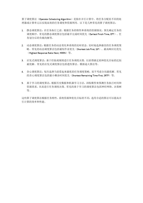
算子调度算法(Operator Scheduling Algorithm)是指在并行计算中,将任务分配给不同的处理器或计算单元以实现高效的任务调度和资源利用。
以下是几种常见的算子调度算法:
1.静态调度算法:在任务执行之前,根据任务的特性和系统的资源情况,预先确定任务的
调度顺序。
常见的静态调度算法包括最早完成时间优先(Earliest Finish Time, EFT)、任务划分后的负载均衡等。
2.动态调度算法:根据任务的动态变化和系统的实时状态,实时地选择最佳的任务调度策
略。
常见的动态调度算法包括最短作业优先(Shortest Job First, SJF)、最高响应比优先(Highest Response Ratio Next, HRRN)等。
3.启发式调度算法:基于经验或规则进行任务调度决策,以求得满足某种优化目标的近似
最优解。
常见的启发式调度算法包括遗传算法、模拟退火算法等。
4.贪心调度算法:每次选择当前看起来最优的任务调度策略,而不考虑全局最优解。
常见
的贪心调度算法包括最小剩余时间优先(Shortest Remaining Time First, SRTF)等。
5.基于学习的调度算法:根据历史数据和机器学习方法,训练模型来预测任务执行时间和
资源需求,从而进行任务调度决策。
常见的基于学习的调度算法包括神经网络、决策树等。
这些算子调度算法根据任务特性、系统资源和优化目标的不同,选用合适的算法可以提高并行计算的效率和性能。
vmd分解 残余分量 带宽 概述说明
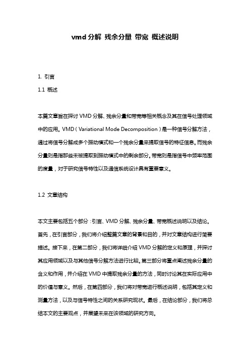
vmd分解残余分量带宽概述说明1. 引言1.1 概述本篇文章旨在探讨VMD分解、残余分量和带宽等相关概念及其在信号处理领域中的应用。
VMD(Variational Mode Decomposition)是一种信号分解方法,通过将信号分解成多个振动模式和一个残余分量来提取信号的特征信息。
而残余分量则是指那些未被提取到振动模式中的剩余部分。
带宽则是指信号中频率范围的度量,对于研究信号特性以及通信系统设计具有重要意义。
1.2 文章结构本文主要包括五个部分:引言、VMD分解、残余分量、带宽概述说明以及结论。
首先,在引言部分,我们将介绍整篇文章的背景和目的,并对文章结构进行简要描述。
接下来,在第二部分,我们将详细介绍VMD分解的定义和原理,并探讨其应用领域以及与其他信号分解方法进行比较。
第三部分将重点阐述残余分量的含义和作用,并介绍在VMD中提取残余分量的方法,同时讨论其在实际应用中的价值与意义。
然后,在第四部分,我们将对带宽进行概述说明,包括其定义和测量方法,以及与信号特性之间的关系研究现状。
最后,在结论部分,我们将总结本文的主要观点,并展望未来在该领域的研究方向。
1.3 目的本文旨在提供读者对于VMD分解、残余分量和带宽等相关概念的深入了解,并探讨其在信号处理和通信系统设计中的应用展望。
通过本文的阐述,读者可以更好地理解VMD分解及其与其他信号分解方法的比较,了解残余分量在VMD中的提取方法以及其在实际应用中所具备的价值与意义。
同时,读者也可以对带宽的定义、测量方法以及其与信号特性之间关系进行全面了解,以期为相关领域的研究和应用提供一定的参考和指导。
2. VMD分解2.1 VMD的定义和原理VMD(Variational Mode Decomposition)是一种信号分解方法,它基于变分原理,将原始信号分解为多个本征模态函数(Intrinsic Mode Functions, IMF)。
VMD通过迭代优化的方式寻找信号中的各个本征模态函数,并根据频率从低到高对这些模态函数进行排序。
vmd pbc wrap用法 -回复
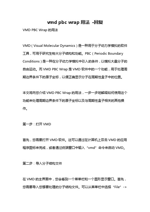
vmd pbc wrap用法-回复VMD PBC Wrap的用法VMD(Visual Molecular Dynamics)是一种用于分子动力学模拟的软件工具,可用于研究生物大分子结构和功能。
PBC(Periodic Boundary Conditions)是一种在分子动力学模拟中引入的条件,以模拟大量分子的自由运动。
而VMD PBC Wrap是VMD软件中的一个功能,用于处理周期边界条件下的原子坐标,以便正确显示分子在周期性盒子中的位置。
本文将向您介绍VMD PBC Wrap的用法,一步一步地解释如何使用这个功能来处理周期边界条件下的原子坐标以及与周期性盒子相关的其他操作。
第一步:打开VMD首先,您需要打开VMD软件。
这可以通过在计算机上双击VMD的应用程序图标来完成,或者通过终端窗口中输入“vmd”命令来启动VMD。
第二步:导入分子结构文件在VMD的主界面中,您会看到一个菜单栏和一个图形显示窗口。
首先,您需要导入您想要处理的分子结构文件。
可以从菜单栏中选择“File”->“New Molecule”来导入文件。
选择您的分子结构文件,并点击“Open”按钮导入文件。
第三步:创建周期性盒子一旦您的分子被导入,您需要为其创建一个周期性盒子。
这样可以模拟实验中的无限空间,使分子在模拟中正确地交互。
在菜单栏中选择“Extensions”->“Analysis”->“Periodic”,然后在弹出的对话框中选择“PBC Wrap”。
第四步:选择操作和参数设置一旦PBC Wrap插件被打开,您将看到一个新的窗口。
在这个窗口中,您可以选择要执行的操作以及相关的参数设置。
最常用的操作之一是“Wrap”,它将确保原子坐标被限制在周期性盒子内。
通过点击“Wrap”按钮,VMD将对所有原子应用这个操作。
此外,您还可以选择将作用于特定分子中的原子。
在VMD的主窗口中,选择要操作的分子,然后在PBC Wrap窗口中选择“Active Molecule”选项卡。
uses -mhard-float -回复
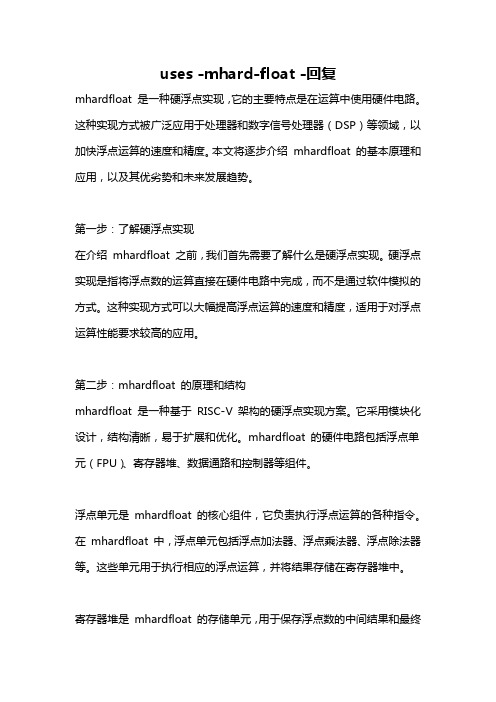
uses -mhard-float -回复mhardfloat 是一种硬浮点实现,它的主要特点是在运算中使用硬件电路。
这种实现方式被广泛应用于处理器和数字信号处理器(DSP)等领域,以加快浮点运算的速度和精度。
本文将逐步介绍mhardfloat 的基本原理和应用,以及其优劣势和未来发展趋势。
第一步:了解硬浮点实现在介绍mhardfloat 之前,我们首先需要了解什么是硬浮点实现。
硬浮点实现是指将浮点数的运算直接在硬件电路中完成,而不是通过软件模拟的方式。
这种实现方式可以大幅提高浮点运算的速度和精度,适用于对浮点运算性能要求较高的应用。
第二步:mhardfloat 的原理和结构mhardfloat 是一种基于RISC-V 架构的硬浮点实现方案。
它采用模块化设计,结构清晰,易于扩展和优化。
mhardfloat 的硬件电路包括浮点单元(FPU)、寄存器堆、数据通路和控制器等组件。
浮点单元是mhardfloat 的核心组件,它负责执行浮点运算的各种指令。
在mhardfloat 中,浮点单元包括浮点加法器、浮点乘法器、浮点除法器等。
这些单元用于执行相应的浮点运算,并将结果存储在寄存器堆中。
寄存器堆是mhardfloat 的存储单元,用于保存浮点数的中间结果和最终结果。
mhardfloat 的寄存器堆通常由多个通用寄存器和浮点寄存器组成,可以同时保存整数和浮点数。
数据通路是mhardfloat 的信息传输通道,负责在各个组件之间传递数据和指令。
数据通路可以将寄存器堆中的数据传送给浮点单元进行运算,并将结果写回寄存器堆。
控制器是mhardfloat 的指令控制单元,通过解析指令并生成相应的控制信号,来控制浮点单元的工作。
控制器还负责协调数据通路和寄存器堆的运作,保证指令的正确执行。
第三步:mhardfloat 的应用领域mhardfloat 作为一种高效的硬浮点实现方案,被广泛应用于处理器和数字信号处理器等领域。
vmd 适应度函数
vmd 适应度函数
VMD(变分模态分解)的适应度函数有多种选择,常见的包括最小包络熵、最小信息熵和最小排列熵等。
1. 最小包络熵:包络熵代表原始信号的稀疏特性,当IMF中噪声较多,特征信息较少时,则包络熵值较大,反之,则包络熵值较小。
因此,以包络熵极小值作为适应度函数,可以优化VMD的结果。
2. 最小信息熵:信息熵是描述系统不确定程度的物理量。
当分解得到的IMF包含故障信息时,由于周期冲击的缘故,其表现地越有序,导致熵值小。
因此,以信息熵最小化作为适应度函数,可以优化VMD的结果。
3. 最小排列熵:排列熵是一种基于序列排序的复杂度测量方法,可以用于分析时间序列数据的复杂性。
在VMD中,以排列熵作为适应度函数,可以优化分解结果的质量。
需要注意的是,适应度函数的选择应该根据具体的应用场景和需求来确定。
不同的适应度函数会对VMD的结果产生不同的影响,需要根据实际情况进行选择和调整。
有关vmd代码
VMD(Variational Mode Decomposition)是一种用于处理非线性和非平稳信号的算法。
它能够将一个复杂的信号分解为若干个本征模态函数(IMF),每个IMF都对应于信号中的一种内在模式。
1.初始化:设置超参数,包括中心频率、带宽等。
2.迭代:在每次迭代中,计算信号的梯度,并根据梯度更新IMF。
3.停止条件:当满足停止条件时,迭代停止。
常见的停止条件包括迭代次数、
残差等。
4.输出:得到若干个IMF和残差。
VMD算法的优点在于它能够自适应地处理非线性和非平稳信号,并且不需要预先设定信号的分解模式。
此外,VMD算法还具有较低的计算复杂度,能够快速地处理大规模数据。
在实际应用中,VMD算法可以用于各种领域,如机械故障诊断、语音识别、图像处理等。
通过将信号分解为若干个IMF,可以更好地理解信号的内在结构和特征,从而为后续的分析和处理提供有力支持。
ocsvm参数

ocsvm参数OCSVM参数(One-Class Support Vector Machine Parameters)一、引言OCSVM(One-Class Support Vector Machine)是一种用于异常检测的机器学习算法。
通过将正常数据映射到高维特征空间,并在此空间中构建分离超平面,OCSVM能够识别出与正常数据有显著差异的异常数据。
本文将深入探讨OCSVM的参数设置与调整,以及它们在模型训练与性能表现中的影响。
二、OCSVM参数概述1. 核函数参数(kernel)OCSVM使用核函数来映射数据到高维空间,常见的核函数有线性核和径向基函数(RBF)核。
线性核适用于数据线性可分的情况,而RBF核适用于非线性可分的情况。
在选择核函数时,需要根据数据的特点进行合理选择。
2. 规则化参数(nu)规则化参数nu控制着OCSVM模型中的训练误差。
较小的nu值会导致更多的训练误差容忍,而较大的nu值会对训练误差容忍较少。
因此,选择合适的nu值可以平衡正常数据和异常数据之间的边界。
3. 异常检测参数(gamma)在使用RBF核函数时,参数gamma会影响模型对异常数据的检测能力。
较小的gamma值会使模型更容易检测到较远的异常数据,而较大的gamma值则更注重于近邻的异常数据。
4. 样本权重参数(sample_weight)通过样本权重参数可以调整不同数据样本在模型训练中的重要性。
合理设置样本权重参数可以提高模型在关键样本上的性能。
三、OCSVM参数调优策略1. 网格搜索(Grid Search)网格搜索是一种常用的参数调优策略,通过尝试不同的参数组合来获得最优参数设置。
对于OCSVM,通过交叉验证等方法,可以遍历不同的核函数参数、规则化参数和异常检测参数组合,选择表现最好的参数组合。
2. 特征选择(Feature Selection)特征选择是指从原始特征中选择出最相关的特征子集来构建模型。
在OCSVM中,特征选择可以通过相关性分析等方法来降低数据的维度,提高模型性能。
- 1、下载文档前请自行甄别文档内容的完整性,平台不提供额外的编辑、内容补充、找答案等附加服务。
- 2、"仅部分预览"的文档,不可在线预览部分如存在完整性等问题,可反馈申请退款(可完整预览的文档不适用该条件!)。
- 3、如文档侵犯您的权益,请联系客服反馈,我们会尽快为您处理(人工客服工作时间:9:00-18:30)。
C
Prepaid - Call forward to voicemail.
1. 2. 3. 4. 5. 6. 7. 8. 9. 10. 11. PSTN or Rogers user call a number roaming. GMSC will send an SRI to the HLR. The HLR will send the SRI_response to the GMSC. GMSC sends an IDP to the prepaid SCP to validate if the users is authorized to get the call. The prepaid SCP responds with an RRBE. GMSC request the HLR for the Routing information to get to the b_number. The HLR request a roaming number (MSRN) from the VPLMN MSC-VLR. On receival of the PRN_response, the MSRN is relayed to the GSMC in the SRI_Ack. An Initial DP (IDP) is sent from the GMSC to the OVMD application. The IDP must contains the following information (calling#, calledMSRN#, OCN). OVMD sends an ISD to the VPLMN MSC/VLR in order to update the forward_to_number to a dummy voicemail routing number (see the VMD number matrix). On receival of the ISD_Ack. The OVMD responds a Continue message. The GMSC calls the MSRN and the far end network alerts the b-number. If the call is not answered, the VPLMN VLR will initiate the call forward to the voicemail number. Since the voicemail number, is not set up in the translation to trigger an IDP to the OVMD system, the call will not be teared down. Normal prepaid call handling resume. Note that when the call to the voicemail will be answered, an ERB will be sent to the prepaid SCP indicating that the call was answered. Another ERB will be sent, to the prepaid SCP, once the call is terminated.
OVMD postpaid CFW to VM
Postpaid OVMD – CFW to external
1. 2. 3. 4. 5. 6. 7. 8. 9. 10.
PSTN or Rogers user call a number roaming. GMSC request the HLR for the Routing information to get the b_number. The HLR request a roaming number (MSRN) from the VPLMN MSC-VLR. An Initial DP (IDP) is sent from the GMSC to the OVMD application. The IDP must contains the following information (calling#, calledMSRN#, OCN). OVMD responds with RRBE, to activate the triggers (T_NoAnswer, T_Busy,…) as well as a Continue message. The GMSC calls the MSRN and the far end network alerts to b-number. If the call is not answered, the OVMD application timer will expire, triggering an ERB due to T_NoAnswer and the call on the MSRN will be released. The OVMD will send a new RRBE and a Connect to the C_number. The GMSC will then call the C_number. Normal call handling resume, but at the end of the call an ERB will be sent by the GMSC to indicate that the call has ended.
HPLMN _MS A
IAM (A call B)
Postpaid OVMD – CFW to third party number SHVPLMN_
MSC STP HLR OVMD MSC MS
SendRoutingInfo (SRI) ProvideRoamingNumber (PRN) PRN_Ack (MSRN) SRI_Ack (PRN) Initial DP (IDP) Request Report BCSM (RRBE) Continue
IAM (GMSC calls the MSRN) ACM Alerting
B
Evernt Report BCSM (ERB) REL (ISUP) RLC (ISUP)
Request Report BCSM (RRBE) Connect (dRoutingInfo (SRI) ProvideRoamingNumber (PRN) PRN_Ack (MSRN) SRI_Ack (PRN) IAM (MSRN) ACM Alerting ANM REL RLC
Different OVMD call scenarios
There are 4 OVMD call flows: • 1. Postpaid - Call forward to Voicemail. • 2. Postpaid - Call forward to a third party number. • 3. Prepaid - Call forward to voicemail. • 4. Prepaid - Call forward to a third party number.
Note that Rogers and Fido subscribers are only allowed to set call forward to North American numbers.
Postpaid - Call forward to Voicemail.
•
•
•
This was the first scenario that was put into service. The goal of this scenario, is to save on Long distance fees, by terminating un-necessary LD established LD trunks. This is call the trombone effect. Basically, when a mobile is roaming out of our network and that a call forward is happening, we use to keep the LD trunk from our GMSC to the VPLMN MSC, even if the call forward is happening. With OVMD, when the application timer expires (or the IAM for the CFW to VM gets to us), the IAM for MSRN leg is being released. A new call is done from our GMSC to the c_number following the instructions from the OVMD application.
Postpaid - Call forward to Voicemail.
1. 2. 3. 4. 5. 6. 7. 8. 9. 10.
PSTN or Rogers user call a number roaming. GMSC request the HLR for the Routing information to get the b_number. The HLR request a roaming number (MSRN) from the VPLMN MSC-VLR. An Initial DP (IDP) is sent from the GMSC to the OVMD application. The IDP must contains the following information (calling#, calledMSRN#, OCN). OVMD responds with RRBE, to activate the triggers (T_NoAnswer, T_Busy,…) as well as a Continue message. The GMSC calls the MSRN and the far end network alerts to b-number. If the call is not answered, the OVMD application timer will expire, triggering an ERB due to T_NoAnswer and the call on the MSRN will be released. The OVMD will send a new RRBE and a connect to the voicemail deposit number. The GMSC will then call the voicemail deposit number. Normal call handling resume, but at the end of the call an ERB will be sent by the GMSC to indicate that the call has ended.
