PD4016ZStackV301亲和组使用教程
Zstack入门教程
Zstack入门教程第一步:安装Zstack从TI官方网站上下载的Zstack为:swrc072c.zip,我想这个压缩包大家都认识。
解压之后为:ZStack-CC2430-1.4.3.exe文件。
这个安装文件大家都会了。
默认安装路径为:C:\Texas Instruments\ZStack-1.4.3。
安装之后在C:\Texas Instruments\ZStack-1.4.3目录下有各PDF 文档为:Getting Started Guide CC2430.pdf,不用多说,这个肯定是要看的。
既然把它放到这么前面,说明它是入门中的入门文档。
下面就简单介绍下这个文档:1、介绍了安装ZStack-CC2430-1.4.3.exe需要的硬件软件条件:需要电脑、操作系统为Windows 2000或Windows XP。
至于更高或更低版本的本人没有尝试。
2、讲了安装流程。
这个有点多余了,这年月哪个有电脑的没有安装上百上千次的软件啊?但是需要强调的是安装路径----默认就好!3、接下来就是让我们看的第一个文档为:Start->Programs->Texas Instruments->ZStack-1.4.3->Z-Stack User’s Guide,既然让我看我就来看看这个文档!!第二步:Z-Stack 用户指导这个文档的更新时间为:2007年12月21日----应该还是比较新的版本。
由于本人英文的却有限,就不翻译了,浏览一遍,把大概意思说下就可以了:1、介绍1.1、适用范围本文档适用于CC2430ZigBee开发板----CC2430ZDK。
2、产品包描述(TI提供的CC2430ZDK工具包)2.1、安装包内容这个就是上面提到的的ZStack-CC2430-1.4.3.exe安装之后的所有内容了。
说白了就是包含Zstack开发所需要的所有软件和文档资料等。
2.2、开发板介绍两块SmartRF04EB 评估版,每个都可以用于CC2430EM评估模块。
赛尔众云-磁盘阵列产品快速操作手册

目录目录 (2)一、设备外观 (3)二、WEB管理界面 (4)1登录管理界面 (4)2进入主界面 (5)3系统设置界面 (5)4.I SCSI设置界面 (8)5.卷设置界面 (12)6.监控管理界面 (16)7.系统维护界面 (18)8.快速安装界面 (21)9卷创建向导 (24)三、系统挂载盘阵 (26)1安装I SCSI客户端软件 (26)2.查看IP地址 (27)3.添加IP地址 (27)4.TARGETS设置 (27)5.系统连接设备 (28)6.添加磁盘 (29)7.创建分区 (30)8.分区格式化 (30)9.磁盘属性 (31)10.磁盘管理及操作 (31)一、设备外观设备图片(供参考,以实物为准)图1正面图2背面二、WEB管理界面1登录管理界面在浏览器里输入IP地址(开机后液晶面板上显示预设地址),直接进入管理界面。
登录界面(用户名:admin密码:1234)2进入主界面3系统设置界面3.1系统设置修改系统名称,调整时间设置。
3.2.网络设定设置管理端口IP地址参数属性3.3.登录设置3.4邮件设置该界面可设置主动推送日志信息,告警信息,错误信息的邮箱。
3.5通告设置4.主机端口设置界面4.1iSCSI端口设置设置外网链接主机端口的IP地址及其他属性点击OP,设置绑定及聚合等功能4.2实体属性设置iSCSI设备实体名称,用于系统识别4.3节点设置4.4会话4.5CHAP账号设置4.6光纤通道设置5.1物理磁盘点击OP,可设置磁盘属性等功能点击创建,设置卷组名称、RAID级别、选择磁盘等属性:点选RAID级别属性:点选“选择PD”按钮,选定RAID组磁盘.点选“OP”按钮可以对卷组做删除等属性修改:5.3用户数据卷点选“创建”按钮,创建新的用户数据卷。
可设置名称、容量等属性。
依据系统是否为64位选择卷的大小。
5.4快照设置5.5逻辑单元设置在“主机/host”设置项下设置需要绑定的主机名称,默认为全部主机。
ZStack V3.10.0 日志服务器 使用教程说明书
3. 验证日志服务器
文档版本:V3.10.0
5
日志服务器 使用教程 / 3 典型场景实践
配置完成后,在日志服务器中输入以下命令,查看是否已正常获取管理节点日志: cat /var/log/test.log
如图 3: 获取管理节点日志所示: 图 3: 获取管理节点日志
如上所述,日志服务器已成功接收到管理节点日志信息,日志服务器配置生效。
云主机(VM Instance)
运行在物理机上的虚拟机实例,具有独立的IP地址,可以访问公共网络,运行应用服务。
镜像(Image)
云主机或云盘使用的镜像模板文件,镜像模板包括系统云盘镜像和数据云盘镜像。
文档版本:V3.10.0
7
日志服务器 使用教程 / 术语表
云盘(Volume)
云主机的数据盘,给云主机提供额外的存储空间,共享云盘可挂载到一个或多个云主机共同使用。
如图 1: 配置syslog server所示: 图 1: 配置syslog server
2. 在云平台创建日志服务器 在ZStack私有云主菜单,点击平台管理 > 日志服务器按钮,进入日志服务器界面,点击添加 日志服务器按钮,参考以下内容进行配置:
• 名称:设置日志服务器名称 • 简介:可选项,可留空不填 • IP地址:输入日志服务器的IP地址
注意事项 • 需要设置日志级别与日志服务器的配置完全一致,才能正常接收日志信息,日志级别支持设 置LOCAL0-9,仅为了匹配日志服务器,无高低之分。 • 需确保云平台管理节点与日志服务器的连通性。 • 配置成功后,管理节点的全部日志均会发送至日志服务器,不区分DEBUG、INFO、ERROR等 输出级别。 • 仅admin/平台管理员支持设置日志服务器。
zstack物理机命令
zstack物理机命令ZStack物理机命令带来了许多便利和效率,让我们能够更加高效地管理和操作物理机。
下面,我将为您介绍一些常用的ZStack物理机命令。
1. 查看物理机状态要查看物理机的状态,您可以使用命令:zstack-cli QueryHost --conditions "state=Enabled"。
这将显示所有已启用的物理机及其相关信息,例如物理机的名称、IP地址、状态等。
2. 添加物理机如果您需要添加新的物理机到ZStack管理平台中,可以使用命令:zstack-cli AddHost --name <物理机名称> --management-ip <物理机IP地址> --username <物理机用户名> --password <物理机密码>。
请注意,这里的<物理机名称>、<物理机IP地址>、<物理机用户名>和<物理机密码>需要根据实际情况进行替换。
3. 删除物理机要删除不再使用的物理机,可以使用命令:zstack-cli DeleteHost --uuid <物理机UUID>。
这将删除指定UUID的物理机及其相关信息。
4. 更新物理机信息如果您需要更新物理机的信息,例如物理机的名称或IP地址,可以使用命令:zstack-cli UpdateHost --uuid <物理机UUID> --name <新物理机名称> --management-ip <新物理机IP地址>。
这将更新指定UUID的物理机的相关信息。
5. 启用/禁用物理机要启用或禁用物理机,可以使用命令:zstack-cli ChangeHostState --uuid <物理机UUID> --state <启用/禁用>。
这将更改指定UUID的物理机的状态。
西部数码301重定向

301转向(或叫301重定向,301跳转)是当用户或搜索引擎向网站服务器发出浏览请求时,服务器返回的HTTP数据流中头信息(header)中的状态码的一种,表示本网页永久性转移到另一个地址。
虚拟主机设置方法:若是我司windows虚拟主机,请按以下流程操作:1.登录管理中心-主机管理-管理-ISAPI筛选器设置-开启自定义的URL静态化支持2.系统提示成功后,点击管理中心-文件管理,找到others\discuz\httpd.conf 文件,点击最右边下载图标将此文件下载到您的计算机3.用记事本打开该文件,在RepeatLimit 32下增加如下两行(假设主机上绑定有三个域名,, ,需要的是将所有的域名都301重定向至,则规则如下:)RewriteCond %{HTTP:Host} !^$RewriteRule (.*) $1 [NC,R=301]说明:将以上规则中的两个替换为您自己的域名即可,两个写一样。
4.将修改好的文件用FTP或者管理中心文件管理的在线上传功能上传到others\discuz\目录替换原文件即可若是我司linux虚拟主机,请按以下流程操作:1.在管理中心-主机管理-管理-文件管理中打开在线文件管理器2.点击文件管理器菜单中的“新建文件”,输入文件名.htaccess3.双击刚才新创建的.htaccess文件,输入以下内容:<IfModule mod_rewrite.c>RewriteEngine OnRewriteCond %{HTTP_HOST} !^$ [NC]RewriteRule ^(.*)$ /$1 [R=301,L]</IfModule>说明:请替换为您新的目标域名,这个规则将会将您的主机绑定的所有域名301重定向到4.点击保存即可立即生效5.通过伪静态限制一个IP或者IP段的规则代码,如果有多条IP限制增加规则条数即可:RewriteCond %{REMOTE_ADDR} ^125.70.243.(.*)$ [NC]RewriteRule (.*) /band.html [NC]独立主机设置方法:如果您是windows系统的,在/rewrite3.rar 下载一个伪静态设置安装包,安装前请先阅读说明文档。
普安磁盘阵列cli手册

普安磁盘阵列cli手册磁盘阵列柜操作手册威科姆科技2007-101、磁盘阵列柜操作模式,提供4种磁盘阵列柜操作方式1)前面板手工操作方式;2、查看系统信息是否与自己得到的硬件信息一致。
3、进入View and edit configuration parameter cacheing parameter optimization for equeyial I、O4、 View and edit configuration parameter hot ide parameter Ma Qeued I、O count: 10245、开始创建RAID,进入 view and edit logical drive6。
按enter7。
按enter8。
创建RAID59。
按enter选中11块盘,留一块作热备,10。
按ESC确定选中的盘11、指定热备盘12、修改参数,改动WritePolicy为Write Back13、把StripeSize改为 256K14、确定创建15、开始初始化16。
等到初始化到100%,选中要分区的逻辑卷。
17。
选择分区大小,第一个分区为1600000MB,第二个分区为剩余容量,先分第一个分区。
18。
进行分区选择分区大小,原则上容量不大于4T时,分2个分区,每个分区的容量是总容量的二分之一;总容量不大于6T时,分3个分区,每个分区的容量是总容量的三分之一;以此类推。
保持每个分区的容量不大于2T即可。
a)第一个分区大小定为1600000MBb)第二个分区容量是剩下的容量19。
退出view and edit logical drive,进入view and edit hot lun。
20。
按enter21、选择CHL0ID101LUN0映射partion 0。
22、按enter,映射partion 0成功。
23、按enter确认24、接着进行CHL0ID102LUN1影射 partion125、选中partion1 ,按enter26。
ZStack协议栈实验
ZStack协议栈实验概述:ZStack协议栈是一个用于物联网(IoT)设备的开源协议栈,它提供了一套标准的通信协议,使得不同的物联网设备能够互相通信和协同工作。
本文将介绍ZStack协议栈的实验内容,包括实验环境的搭建、实验步骤和实验结果的分析。
实验环境搭建:为了进行ZStack协议栈的实验,首先需要搭建实验环境。
以下是搭建实验环境的步骤:1. 硬件准备:准备一台开发板或者物联网设备,确保其与计算机可以进行连接。
2. 软件准备:下载并安装ZStack协议栈的开发工具包,该工具包包含了开发ZStack协议栈所需的各种工具和库文件。
3. 连接硬件:使用USB线将开发板或物联网设备与计算机连接,并确保连接成功。
4. 配置环境:根据ZStack协议栈的官方文档,配置开发环境并导入相应的库文件。
实验步骤:实验环境搭建完成后,可以开始进行ZStack协议栈的实验。
以下是实验步骤的简要介绍:1. 创建网络:使用ZStack协议栈的工具包,创建一个物联网设备网络。
可以选择使用其中的示例代码,或者根据实际需求编写代码。
2. 添加设备:将其他物联网设备添加到已创建的网络中,以建立设备之间的通信。
可以使用工具包提供的API或者示例代码进行设备的添加。
3. 通信测试:进行设备之间的通信测试,例如发送数据包、接收数据包、远程控制等。
通过观察和分析通信结果,可以评估ZStack协议栈的性能和可靠性。
4. 功能扩展:根据实际需求,对ZStack协议栈进行功能扩展和定制化开发。
可以添加更多的传感器、控制模块或者其他自定义功能。
实验结果分析:完成实验步骤后,可以对实验结果进行分析。
以下是分析实验结果的一些建议:1. 性能评估:分析实验中的通信延迟、传输速率、能耗等指标,评估ZStack协议栈的性能。
可以与其他协议栈进行对比,以得出结论。
2. 可靠性分析:观察实验中的通信稳定性,分析出现的错误或异常情况,并提出改进建议。
3. 扩展性评估:根据实验中的功能扩展操作,评估ZStack协议栈的扩展性和灵活性。
实验8—基于Z-Stack的无线自组网实验
实验8—基于Z-Stack的⽆线⾃组⽹实验实验题⽬:实验8—基于Z-Stack的⽆线⾃组⽹实验实验时间:2015.12.24⼀、实验⽬的:学习TI ZStack2007协议栈内容,掌握CC2530模块⽆线组⽹原理及过程。
有关Z-Stack2007协议栈的具体内容,请参考附录中相关说明及TI官⽅⽂档。
使⽤IAR 开发环境设计程序,ZStack-2.3.0-1.4.0协议栈源码例程SampleApp⼯程基础上,实现⽆线组⽹及通讯。
即协调器⾃动组⽹,终端节点⾃动⼊⽹,并发送周期信息“~HELLO!~”⼴播,协调器接收到消息后将数据通过串⼝发送给PC 计算机。
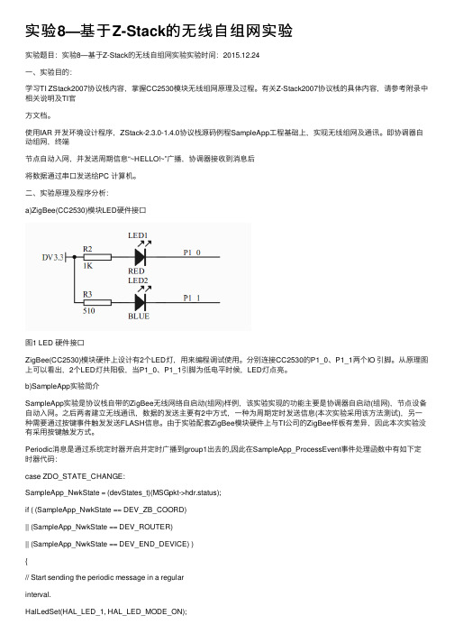
⼆、实验原理及程序分析:a)ZigBee(CC2530)模块LED硬件接⼝图1 LED 硬件接⼝ZigBee(CC2530)模块硬件上设计有2个LED灯,⽤来编程调试使⽤。
分别连接CC2530的P1_0、P1_1两个IO 引脚。
从原理图上可以看出,2个LED灯共阳极,当P1_0、P1_1引脚为低电平时候,LED灯点亮。
b)SampleApp实验简介SampleApp实验是协议栈⾃带的ZigBee⽆线⽹络⾃启动(组⽹)样例,该实验实现的功能主要是协调器⾃启动(组⽹),节点设备⾃动⼊⽹。
之后两者建⽴⽆线通讯,数据的发送主要有2中⽅式,⼀种为周期定时发送信息(本次实验采⽤该⽅法测试),另⼀种需要通过按键事件触发发送FLASH信息。
由于实验配套ZigBee模块硬件上与TI公司的ZigBee样板有差异,因此本次实验没有采⽤按键触发⽅式。
Periodic消息是通过系统定时器开启并定时⼴播到group1出去的,因此在SampleApp_ProcessEvent事件处理函数中有如下定时器代码:case ZDO_STATE_CHANGE:SampleApp_NwkState = (devStates_t)(MSGpkt->hdr.status);if ( (SampleApp_NwkState == DEV_ZB_COORD)|| (SampleApp_NwkState == DEV_ROUTER)|| (SampleApp_NwkState == DEV_END_DEVICE) ){// Start sending the periodic message in a regularinterval.HalLedSet(HAL_LED_1, HAL_LED_MODE_ON);osal_start_timerEx( SampleApp_TaskID,SAMPLEAPP_SEND_PERIODIC_MSG_EVT,SAMPLEAPP_SEND_PERIODIC_MSG_TIMEOUT );}else{// Device is no longer in the network}break;当设备加⼊到⽹络后,其状态就会变化,对所有任务触发ZDO_STATE_CHANGE 事件,开启⼀个定时器。
中国邮政速递PDA全流程操作使用手册.ppt

普通用户功能—发运(装车)
勾核方式的逐件扫描
选择“勾核”方式, 逐件扫描要发运的总包号和邮件号。 当预告信息中包含此条码时,该条码前显示“√”
普通用户功能—发运(装车)
勾核方式的逐件扫描
当预告信息中不包含此条码时,提示“预告信息中不包含此条 码,是否追加?”,如果选“是”,在条码显示框中追加此条码, 并在条码前显示“X”。选择“否”,将不追加此条码
无预告信息逐件交接
当无预告信息时,需要进行 逐件扫描交接。扫描完成后 按“上传” 键进行上传
未上传退出系统提示
在所有扫描界面,如果已扫描了条码信息, 但没有提交上传,按“*”返回时,系统会 提示存在未上传数据
数据上传重复提示
在所有数据提交上传界面,当提交的数据与后台一 有数据重复时,该界面首先会提示“上传数据总数 /重复件数”其中邮件号码前的标志为“×”的邮 件为重复邮件。在该界面可选择“强制”,“删除 上传”和“返回”操作。
滞留方式的逐件扫描
滞留件扫描成功后,点击“批量”按钮,将 剩余所有信息批量勾核。批量勾核完成后, 点击“上传”,将发运数据上传,
普通用户功能—数据统计
数据统计
发运(装车)界面,点击数据统计按钮,进 入数据统计界面,在此界面可选择不同格口 进行数据统计,可以通过1、2、3、4分别 显示应发运、已扫描、少件、多件信息,并 在邮件列表框显示详细信息,
普通用户功能—发运(装车)
所有要发运的信息扫描完成后,点击“上传” 或按“√”键上传数据
普通用户功能—发运(装车)
滞留方式的逐件扫描
在逐件扫描方式选项,选择“滞留”方式,此时只 扫描封发信息中未装车的条码信息,扫描后系统将从已 下载的封发预告信息中剔除掉扫描的条码信息。
puvc301说明书

0 本手册之向导本手册旨在使客户能够快速了解本产品,在使用中可以快速、方便地参考。
由于本产品在实际工程中配置比较复杂,所以敬请客户在使用前与本公司的系统工程师进行讨论,并在使用中参考相关手册,同时敬请客户参考以下的术语解释。
嵌入式系统:将某些与外部耦合较小的相对独立的部分设计成单独的模块,以较简单的接口形式提供,模块内部的修改不会影响到外部使用,较为通用,而且提高了系统的可靠性和扩展性。
软件和硬件的设计都可以采用嵌入式系统设计思想。
数字图像处理:以提取某些特征信息或其它信息为目的,而对数字图像象素矩阵进行的一些有意义的数值运算。
算法:数学运算的原理或公式。
开关量:只有“高电平”和“低电平”两种状态的输入信号量。
控制输出点:在设备中就是一个继电器的输出,本设备中为剔除机构(气阀)输入点。
组态软件:为了方便设备参数配置和维护而专门设计的上层用户软件,用户通过该软件可以方便地对设备进行维护和监控。
实时操作系统:要求在确定的时间内对事件作出响应,并能按确定的时间顺序处理事件的操作系统。
PLC可编程逻辑:Programmer Logic Controller,通过编程界面将控制流程编辑成代码,该代码下载给执行程序后,执行程序通过解释控制流程代码产生逻辑输出。
1概述PU-VC301是深圳市博联达科技发展有限公司为了满足卷烟生产厂生产线的需要而开发的智能型小包分检设备,该设备采用高清晰高分辨率的彩色CCD传感器和处理显示内核,处理速度高,可以检测和剔除RGB三色中的细小次品小包。
广泛适用于烟厂卷接包生产线的小包外包质量监控,尤其适合于生产速度快且烟包间隔不定的软包和硬包生产线场合。
具有配置灵活、安装方便、精度高、可靠性好、性能价格比高的特点。
在不影响生产线的原有控制程序的情况下,可以安装在小包机与小包薄膜包装机之间的输送带上的任何位置。
PU-VC301能帮助生产线实现如下目标:◆降低因小包包装质量引起的投诉。
istack用法
istack用法iStack是一种智能堆叠技术,适用于S2700、S3700、S5700和S6700中低端交换机。
它通过将多台物理交换机在逻辑上合并成一台交换机,从而提升交换机的性能。
在使用iStack时,需要遵循以下步骤:1.配置主交换机:首先需要选择一台交换机作为主交换机,负责管理整个堆叠系统。
主交换机需要显示为master。
2.配置备用交换机:备用交换机负责在主交换机故障时进行接替。
一个堆叠系统中有且只有一个备用交换机,显示为Standby。
3.配置从交换机:除了主交换和备用交换外,其他所有交换机都是从交换机。
从交换机包括主交换机的其他端口和备用交换机的其他端口。
4.配置堆叠ID:为了方便管理堆叠中的交换机,每一个交换机都有一个唯一的堆叠ID。
堆叠ID默认为0,可以通过手动配置进行修改。
5.配置堆叠优先级:在堆叠中选举主和备交换机时,优先级高的为主,优先级最高的为备。
在使用iStack时,需要注意以下几点:1.iStack最多支持9台交换机合并,而在CSS中只支持2台交换机合并。
2.iStack将交换机性能翻倍提升,可以增加接口数量、背板带宽、转发速率、提高可靠性等。
3.在iStack中,所有的控制和管理报文都只会在主交换上运行,当主设备故障时备用设备才会接管所有数据流量的转发工作。
4.只有在同一个iStack下的设备才会认为是iStack设备,设备间会有设备之间的互联地址(即网关地址)以及设备自己的地址(即管理地址)。
5.在同一个iStack下所有的设备只能有一个主控设备,主控设备负责进行对设备的配置、监控和管理等操作。
PNOZ mmc1p可配置紧凑型控制系统操作手册说明书

PNOZ mmc1p}Configurable compact control systems PNOZmulti MiniThis document is a translation of the original document.All rights to this documentation are reserved by Pilz GmbH & Co. KG. Copies may be made for internal purposes. Suggestions and comments for improving this documentation will be gratefully received.Source code from third-party manufacturers or open source software has been used for some components. The relevant licence information is available on the Internet on the Pilz homepage.Pilz®, PIT®, PMI®, PNOZ®, Primo®, PSEN®, PSS®, PVIS®, SafetyBUS p®,SafetyEYE®, SafetyNET p®, the spirit of safety® are registered and protected trademarks of Pilz GmbH & Co. KG in some countries.SD means Secure Digital1.2Using the documentation5 1.3Definition of symbols52.2Unit features7 2.3Front view73.2System requirements9 3.3Safety regulations10 3.3.1Use of qualified personnel10 3.3.2Warranty and liability10 3.3.3Disposal10 3.3.4For your safety104.2Block diagram115.2Dimensions12 5.3Connect the base unit and expansion modules136.2Preparing for operation14 6.2.1Download modified project to the PNOZmulti safety system14 6.3Ethernet interfaces15 6.3.1RJ45 interfaces ("Ethernet")15 6.3.2Requirements of the connection cable and connector15 6.3.3Interface configuration15 6.3.4RJ45 connection cable16 6.3.5Process data exchange177.1.1Display elements for device diagnostics18 7.2Reset Ethernet connection settings199.2Accessories221Introduction1.1Validity of documentationThis documentation is valid for the product PNOZ mmc1p. It is valid until new documenta-tion is published.This operating manual explains the function and operation, describes the installation andprovides guidelines on how to connect the product.1.2Using the documentationThis document is intended for instruction. Only install and commission the product if youhave read and understood this document. The document should be retained for future ref-erence.1.3Definition of symbolsInformation that is particularly important is identified as follows:NOTICEThis describes a situation in which the product or devices could be dam-aged and also provides information on preventive measures that can betaken. It also highlights areas within the text that are of particular import-ance.INFORMATIONThis gives advice on applications and provides information on special fea-tures.2Overview2.1Scope of supply}Expansion module PNOZ mmc1p}Jumper2.2Unit featuresUsing the product PNOZ mmc1p:Communication module for connection to a base unit from the configurable control systemsPNOZmultiMini.The product has the following features:}Can be configured in the PNOZmulti Configurator} 2 Ethernet interfaces}Status indicators for supply voltage, communication and errors}Max. 1 communication module can be connected to the left of the base unit PNOZmulti Mini2.3Front viewLegend:}Link1, Link2:Ethernet interfaces}LEDs:–Power–Link1–Traffic1–Link2–Traffic2–Fault3Safety3.1Intended useThe expansion module PNOZ mmc1p is used for communication of the configurable controlsystems PNOZmulti Mini via Ethernet.The expansion module may only be connected to a base unit PNOZmulti Mini (for details ofthe base units PNOZmulti Minithat can be connected, refer to the document "PNOZmulti System Expansion").The configurable small control systems PNOZmulti are used for the safety-related interrup-tion of safety circuits and are designed for use in:}E-STOP equipment}Safety circuits in accordance with VDE 0113 Part 1 and EN 60204-1The expansion module may not be used for safety-related functions.The following is deemed improper use in particular:}Any component, technical or electrical modification to the product}Use of the product outside the areas described in this manual}Use of the product outside the technical details (see Technical details [ 20]).NOTICEEMC-compliant electrical installationThe product is designed for use in an industrial environment. The productmay cause interference if installed in other environments. If installed in otherenvironments, measures should be taken to comply with the applicablestandards and directives for the respective installation site with regard to in-terference.3.2System requirementsPlease refer to the "Product Modifications PNOZmulti" document in the "Version overview"section for details of which versions of the base unit and PNOZmulti Configurator can beused for this product.3.3Safety regulations3.3.1Use of qualified personnelThe products may only be assembled, installed, programmed, commissioned, operated,maintained and decommissioned by competent persons.A competent person is someone who, because of their training, experience and current pro-fessional activity, has the specialist knowledge required to test, assess and operate thework equipment, devices, systems, plant and machinery in accordance with the generalstandards and guidelines for safety technology.It is the company’s responsibility only to employ personnel who:}Are familiar with the basic regulations concerning health and safety / accident preven-tion}Have read and understood the information provided in this description under "Safety"}And have a good knowledge of the generic and specialist standards applicable to the specific application.3.3.2Warranty and liabilityAll claims to warranty and liability will be rendered invalid if}The product was used contrary to the purpose for which it is intended}Damage can be attributed to not having followed the guidelines in the manual}Operating personnel are not suitably qualified}Any type of modification has been made (e.g. exchanging components on the PCB boards, soldering work etc.).3.3.3Disposal}When decommissioning, please comply with local regulations regarding the disposal of electronic devices (e.g. Electrical and Electronic Equipment Act).3.3.4For your safetyThe unit meets all the necessary conditions for safe operation. However, you should alwaysensure that the following safety requirements are met:}This operating manual only describes the basic functions of the unit. The expanded functions are described in the PNOZmulti Configurator's online help. Only use thesefunctions once you have read and understood the documentations.}Do not open the housing or make any unauthorised modifications.}Please make sure you shut down the supply voltage when performing maintenance work (e.g. exchanging contactors).Function description4Function description4.1Unit propertiesThe product PNOZ mmc1p has two Ethernet interfaces to}Download the project}Read the diagnostic data}Set virtual inputs for standard functions}Read virtual outputs for standard functionsvia Ethernet (TCP/IP, Modbus/TCP).Information on diagnostics via the Ethernet interfaces can be found in the document entitled" PNOZmulti Mini communication interfaces".The connection to Ethernet is made via the two 8-pin RJ45 sockets.The Ethernet interface is configured in the PNOZmulti Configurator and is described in theonline help for the PNOZmulti Configurator.4.2Block diagram5Installation5.1General installation guidelines}The unit should be installed in a control cabinet with a protection type of at least IP54.}Fit the safety system to a horizontal mounting rail. The venting slots must face upwards and downwards. Other mounting positions could destroy the safety system.}Use the notch on the rear of the unit to attach it to a mounting rail.}In environments exposed to heavy vibration, the unit should be secured using a fixing element (e.g. retaining bracket or end angle).}Push the unit upwards or downwards before lifting it from the mounting rail.}To comply with EMC requirements, the mounting rail must have a low impedance con-nection to the control cabinet housing.}The ambient temperature of the PNOZmulti units in the control cabinet must not exceed the figure stated in the technical details, otherwise air conditioning will be required.NOTICEDamage due to electrostatic discharge!Electrostatic discharge can damage components. Ensure against dischargebefore touching the product, e.g. by touching an earthed, conductive sur-face or by wearing an earthed armband.5.2Dimensions5.3Connect the base unit and expansion modulesConnect the base unit and the expansion module as described in the operating instructionsfor the base units.}Connect the black/yellow terminator to the expansion module.}Install the expansion module in the position in which it is configured in the PNOZmulti Configurator.The position of the expansion modules is defined in the PNOZmulti Configurator. The ex-pansion modules are connected to the left or right of the base unit, depending on the type.Please refer to the document "PNOZmulti System Expansion" for details of the number ofmodules that can be connected to the base unit and the module types.6Commissioning6.1General wiring guidelinesThe wiring is defined in the circuit diagram of the PNOZmulti Configurator.Please note:}Information given in the Technical details [ 20] must be followed.}Use copper wire that can withstand 75° C.6.2Preparing for operationDetection and activation of the Ethernet interface, depending on the USB interface on thebase unit:}USB interface on the base unit not connectedIf the USB interface on the base unit is not connected, the Ethernet interface will be de-tected and activated by the base unit as soon as the communication module has beenconnected to the base unit.}USB interface on the base unit connectedIf the USB interface on the base unit is already connected, the "Ethernet" interface willfirst need to be selected on the base unit display to enable the Ethernet interface on thebase unit to be detected and activated (see operating manual for the base unit for de-tails of the setting).6.2.1Download modified project to the PNOZmulti safety systemAs soon as an additional expansion module has been connected to the system, the projectmust be amended using the PNOZmulti Configurator. Proceed as described in the operat-ing instructions for the base unit.NOTICEFor the commissioning and after every program change, you must checkwhether the safety devices are functioning correctly.6.3Ethernet interfaces6.3.1RJ45 interfaces ("Ethernet")Two free switch ports are provided as Ethernet interfaces via an internal autosensingswitch. The autosensing switch automatically detects whether data transfer is occurring at10 Mbit/s or 100 Mbit/s.INFORMATIONThe connected subscribers must support the autosensing/autonegotiation function. If not, the communication partner must be set permanently to "10Mbit/s, half duplex".The switch's automatic crossover function means there is no need to distinguish on the connection cable between patch cable (uncrossed data line connection) and crossover cable (crossover data line connection). The switch automatically creates the correct data line connection internally. Patch cable can therefore be used as the connection cable for end devices as well as cascading.Both Ethernet interfaces use RJ45 technology.6.3.2Requirements of the connection cable and connectorThe following minimum requirements must be met:}Ethernet standards (min. Category 5) 10BaseT or 100BaseTX }Double-shielded twisted pair cable for industrial Ethernet use }Shielded RJ45 connectors (industrial connectors)6.3.3Interface configuration6.3.4RJ45 connection cableNOTICEWith the plug-in connection please note that the data cable and connectorhave a limited mechanical load capacity. Appropriate design measuresshould be used to ensure that the plug-in connection is insensitive to in-creased mechanical stress (e.g. through shock, vibration). Such measuresinclude fixed routing with strain relief, for example.6.3.5Process data exchangeThe RJ45 interfaces on the internal autosensing switch enable process data to be ex-changed with other Ethernet subscribers within a network.The product PNOZ mmc1p can also be connected to Ethernet via a hub (hub or switch).communication module withPNOZmulti Mini base unit + Fig.: PNOZmulti as Ethernet subscriber - possible topologies7Operation7.1MessagesWhen the supply voltage is switched on, the PNOZmulti safety system copies the configur-ation from the chip card.The LEDs “POWER”, “DIAG”, “FAULT”, “IFAULT” and “OFAULT” will light up on the baseunit.The safety system PNOZmulti is ready for operation when the "POWER" and "RUN" LEDson the base unit and the "POWER" LED on the PNOZ mmc1p are lit continuously.7.1.1Display elements for device diagnosticsLegendLED onLED flashesLED off7.2Reset Ethernet connection settingsThe Ethernet connection settings of the base unit can be configured in the PNOZmulti Con-figurator.You can reset the base unit's Ethernet connection settings to the default settings.Proceed as follows:}Switch off the supply voltage}Remove the chip card}Restart the base unit without the chip card inserted.The Ethernet connection settings are now reset to the default settings.Technical details8Technical detailsfor Module supplyinternal Via base unitVoltage3,3 VKind DCVoltage tolerance-2 %/+2 %Power consumption1,0 WDevice type SlaveConnection RJ45In accordance with the standard EN 60068-2-14Temperature range0 - 60 °CStorage temperatureIn accordance with the standard EN 60068-2-1/-2Temperature range-25 - 70 °CClimatic suitabilityIn accordance with the standard EN 60068-2-30, EN 60068-2-78 Humidity93 % r. h. at 40 °C Condensation during operation Not permittedEMC EN 61131-2VibrationIn accordance with the standard EN 60068-2-6Frequency10,0 - 150,0 HzAcceleration1gShock stressIn accordance with the standard EN 60068-2-27Acceleration15gDuration11 msMax. operating height above sea level2000 mAirgap creepageOvervoltage category IIPollution degree2Rated insulation voltage30 VTechnical detailsIn accordance with the standard EN 60529Mounting area (e.g. control cabinet)IP54Housing IP20DIN railTop hat rail35 x 7,5 EN 50022Recess width27 mmMax. cable lengthMax. cable length per input0,1 kmMaterialBottom PCFront PCTop PCDimensionsHeight100,0 mmWidth22,5 mmDepth120,0 mmWeight100 gWhere standards are undated, the 07/2010 latest editions shall apply.Order reference9Order reference 9.1Product9.2AccessoriesTerminator, jumperSupportTechnical support is available from Pilz round the clock. Americas Brazil+55 11 97569-2804Canada+1 888-315-PILZ (315-7459)Mexico+52 55 5572 1300USA (toll-free)+1 877-PILZUSA (745-9872)Asia China+86 21 60880878-216 Japan+81 45 471-2281South Korea +82 31 450 0680Australia +61 3 95446300Europe Austria+43 1 7986263-0Belgium, Luxembourg +32 9 3217575France+33 3 88104000Germany+49 711 3409-444Ireland+353 21 4804983Italy+39 0362 1826711Scandinavia +45 74436332Spain+34 938497433Switzerland +41 62 88979-30The Netherlands +31 347 320477Turkey+90 216 5775552United Kingdom +44 1536 462203You can reach our international hotline on: +49 711 3409-444 ****************C M S E ®, I n d u r a N E T p ®, P A S 4000®, P A S c a l ®, P A S c o n fi g ®, P i l z ®, P I T ®, P L ID ®, P M C p r i m o ®, P M C p r o t e g o ®, P M C t e n d o ®, P M D ®, P M I ®, P N O Z ®, P r i m o ®, P SE N ®, P S S ®, P V I S ®, S a f e t y B U S p ®, S a f e t y E Y E ®, S a f e t y N E T p ®, T h E S P I r I T O f S A f E T Y ® a r e r e g i s t e r e d a n d p r o t e c t e d t r a d e m a r k s o f P i l z G m b h & C o . K G i n s o m e c o u n t r i e s . W e w o u l d p o i n t o u t t h a t p r o d u c t f e a t u r e s m a y v a r y f r o m t h e d e t a i l s s t a t e d i n t h i s d o c u m e n t , d e p e n d i n g o n t h e s t a t u s a t t h e t i m e o f p u b l i c a t i o n a n d t h e s c o p e o f t h e e q u i p m e n t . W e a c c e p t n o r e s p o n s i b i l i t y f o r t h e v a l i d i t y , a c c u r a c y a n d e n t i r e t y o f t h e t e x t a n d g r a p h i c s p r e s e n t e d i n t h i s i n f o r m a t i o n . P l e a s e c o n t a c t o u r T e c h n i c a l S u p p o r t i f y o u h a v e a n y q u e s t i o n s .Pilz develops environmentally-friendly products using ecological materials and energy-saving technologies. Offices and production facilities are ecologically designed, environmentally-aware and energy-saving. So Pilz offers sustainability, plus the security of using energy-efficient products and environmentally-friendly solutions.Pilz Gmbh & Co. KG felix-Wankel-Straße 2 73760 Ostfildern, Germany Tel.: +49 711 3409-0 fax: +49 711 3409-133 100X X X X -D E -0X 0-0-1-3-000, 2015-00 P r i n t e d i n G e r m a n y © P i l z G m b h & C o . K G , 20151002102-E N -02, 2016-04 P r i n t e d i n G e r m a n y © P i l z G m b H & C o . K G , 2015。
PD4016ZStackV301亲和组使用教程

创建亲和组 在亲和组管理界面,点击创建亲和组,弹出创建亲和组界面,可参考以下示例输入相应内容: • 名称:设置亲和组名称 • 简介:可选项,可留空不填 • 策略:选择亲和组策略 目前ZStack提供针对云主机与物理机的两种亲和组策略: • 反亲和组(非强制): 将亲和组内的云主机尽量分配到不同物理机上,当没有更多物理机可分配时,回归普通分配 策略。 • 反亲和组(强制):
文档版本:V3.0.1
5
亲和组 使用教程 / 3 使用入口
亲和组详情页包含以下ቤተ መጻሕፍቲ ባይዱ页面: • 基本属性:
显示当前亲和组的基本信息,包括:亲和组名称、简介、绑定云主机数量、指定策略、亲和组类 型和UUID等。
注: 亲和组创建后,必已指定策略和类型,且只可修改名称和简介,其它参数不可修改。
• 云主机:
显示当前亲和组绑定的全部云主机列表,支持绑定新的云主机到亲和组、或从亲和组解绑云主 机。 • 审计:
文档版本:V3.0.1
I
亲和组 使用教程 / 目录
目录
版权声明.................................................................................................... I 1 介绍.........................................................................................................1 2 前提.........................................................................................................3 3 使用入口................................................................................................. 4
Z-STACK按键

Z-STACK按键的使用总结#define HAL_KEY_SW_6_ENABLE// SW_6的IO端口#define HAL_KEY_SW_6_PORT P0//SW6接到IO端口的位数P0.1#define HAL_KEY_SW_6_BIT HAL_KEY_BIT1// SW_6的IO端口选择#define HAL_KEY_SW_6_SEL P0SEL// SW_6的IO端口方向#define HAL_KEY_SW_6_DIR P0DIR// SW_6的IO端口中断使能#define HAL_KEY_SW_6_IEN IEN1// SW_6的IO端口中断使能的掩码#define HAL_KEY_SW_6_IENBIT HAL_KEY_BIT5// SW_6的IO端口中断的边沿选择#define HAL_KEY_SW_6_EDGE HAL_KEY_RISING_EDGE // SW_6的IO端口边沿掩码#define HAL_KEY_SW_6_EDGEBIT HAL_KEY_BIT0// SW_6的IO端口总中断#define HAL_KEY_SW_6_ICTL PICTL// SW_6的IO端口总中断掩码#define HAL_KEY_SW_6_ICTLBIT HAL_KEY_BIT3// SW_6的IO端口中断标志位#define HAL_KEY_SW_6_PXIFG P0IFG按键主要使用的是IO来设置的,这里需要设置的参数主要有按键设置在哪个端口以及掩码、按键中断使能标志以及掩码、引起中断的上升沿还是下降沿以及掩码涉及的主要寄存器有PICTL端口输入中断控制IEN1端口0总中断使能IEN2 端口1和2总中断使能比如需要设置HAL_KEY_SW_6为P0.4为输入下降沿有效中断设置如下:#define HAL_KEY_SW_6_ENABLE#define HAL_KEY_SW_6_PORT P0#define HAL_KEY_SW_6_BIT HAL_KEY_BIT4#define HAL_KEY_SW_6_SEL P0SEL#define HAL_KEY_SW_6_DIR P0DIR#define HAL_KEY_SW_6_IEN IEN1#define HAL_KEY_SW_6_IENBIT HAL_KEY_BIT5#define HAL_KEY_SW_6_EDGE HAL_KEY_FALLING_EDGE#define HAL_KEY_SW_6_EDGEBIT HAL_KEY_BIT0#define HAL_KEY_SW_6_ICTL PICTL#define HAL_KEY_SW_6_ICTLBIT HAL_KEY_BIT4#define HAL_KEY_SW_6_PXIFG P0IFG比如需要设置HAL_KEY_SW_6为P2.1为输入上升沿有效中断设置如下:#define HAL_KEY_SW_6_ENABLE#define HAL_KEY_SW_6_PORT P2#define HAL_KEY_SW_6_BIT HAL_KEY_BIT4#define HAL_KEY_SW_6_SEL P2SEL#define HAL_KEY_SW_6_DIR P2DIR#define HAL_KEY_SW_6_IEN IEN2#define HAL_KEY_SW_6_IENBIT HAL_KEY_BIT1#define HAL_KEY_SW_6_EDGE HAL_KEY_RISING_EDGE#define HAL_KEY_SW_6_EDGEBIT HAL_KEY_BIT2#define HAL_KEY_SW_6_ICTL PICTL#define HAL_KEY_SW_6_ICTLBIT HAL_KEY_BIT5#define HAL_KEY_SW_6_PXIFG P2IFG这样设置后就可以正常使用KEY 中断。
AX301用户手册REV4.0

AX301用户手册REV4.0FPGA黑金开发平台用户手册AX301REV 4.0芯驿电子科技(上海)有限公司黑金动力社区/doc/8b25383277232f60ddcca1b5.ht ml文档版本控制目录一、简介 (4)二、电源 (7)三、FPGA (8)1)JTAG接口 (9)2)配置芯片:M25P16 (9)3)FPGA供电引脚 (10)4)FPGA时钟输入引脚 (11)四、50M有源晶振 (12)五、SDRAM (12)六、EEPROM 24LC04 (15)七、PS/2接口 (16)八、实时时钟DS1302 (17)九、数码管 (18)十、USB转串口 (20)十一、VGA接口 (21)十二、蜂鸣器 (24)十三、SD卡槽 (25)十四、扩展口 (26)十五、LED (28)十六、按键 (29)十七、摄像头接口 (30)十八、7寸TFT接口 (31)FPGA黑金开发平台学生版2014款正式发布了,此款开发平台是在前两款学生版的基础上升级而来,型号为:AX301。
虽然是一款入门级的FPGA开发平台,但是我们不管是在PCB设计上,还是在整个构造上都花费了很多的心思,真可谓“简约而不简单”。
一、简介在这里,对这款FPGA开发平台进行简单的功能介绍。
此款开发板使用的是ALERA公司的CYCLONE IV系列FPGA,型号为EP4CE6F17C8,256个引脚的FBGA封装。
根据ALTERA官方的数据,CYCLONE IV相对CYCLONE III来说,功耗减少25%,如下图所示此款FPGA的资源如下图所示:其中,主要的参数,逻辑单元LE:6272;乘法器LAB:392;RAM:276480bit;IO数量:179个;内核电压:1.15V-1.25V(推荐1.2V); 工作温度:0-85℃图为整个系统的结构示意图:通过这个示意图,我们可以看到,我们这个开发平台所能实现的功能。
●USB接口供电方式,只需要一根USB线就可以完成对开发板的供电。
Z-Stack协议栈ZDO绑定和管理API
Z-Stack协议栈ZDO绑定和管理API1 ZDO绑定APIZDO绑定API创建并发送ZDO绑定请求和相应。
所有的绑定信息(表)被zigbee协调器保持,因此,只有zigbee协调器可以接收绑定请求。
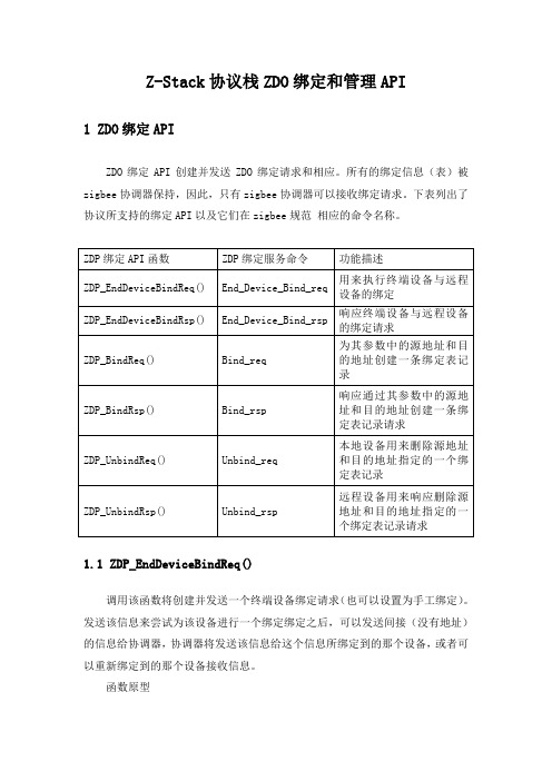
下表列出了协议所支持的绑定API以及它们在zigbee规范相应的命令名称。
1.1 ZDP_EndDeviceBindReq()调用该函数将创建并发送一个终端设备绑定请求(也可以设置为手工绑定)。
发送该信息来尝试为该设备进行一个绑定绑定之后,可以发送间接(没有地址)的信息给协调器,协调器将发送该信息给这个信息所绑定到的那个设备,或者可以重新绑定到的那个设备接收信息。
函数原型afStatus_t ZDP_EndDeviceBindReq( zAddrType_t *dstAddr,uint16 LocalCoordinator,byte endPoint,uint16 ProfileID,byte NumInClusters, cId_t *InClusterList, byte NumOutClusters, cId_t *OutClusterList, byte SecurityEnable )参数细节dstAddr - 目的地址。
LocalCoordinator - 已知的设备的父协调器的16位网络地址。
endPoint - 应用的端点/接口。
ProfileID - 作为簇ID参考的应用的规范ID。
NumInClusters —在输入簇列表中的簇ID的编号。
InClusterList - 输入簇ID(每一个字节)的数组。
NumOutClusters - 在输出簇列表中的簇ID的编号。
OutClusterList - 输出簇ID(每一个字节)的数组。
SecurityEnable - 信息的安全类型。
返回值afStatus_t - 该函数使用AF来发送信息,因此状态值为AF状态值,它们在ZComDef.h文件中的ZStatus_t中定义。
zstack OTA开启教程
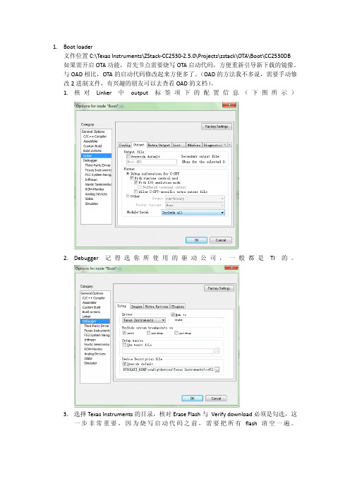
macTaskInit( taskID++ );
nwk_init( taskID++ );
Hal_Init( taskID++ );
#if defined( MT_TASK )
MT_TaskInit( taskID++ );
#endif
APS_Init( taskID++ );
ZDApp_Init( taskID++ );
4. 设置完成后,编译一下,然后下载到节点中。
2. 移植信息配置 根据 TI 的 OTA 文档,按照它的移植方法,其实最后还是漏了几点步骤没有说明,导致 我移植过程中,摸索和很久才有发现问题,起初到 TI 的 e2e 论坛发帖求助也得不到太大 帮助,后来对比了 HA 的那个 OTA 例子,不停地尝试,终于找到了解决方法。下面我简 单说一说主要步骤。以 sensordemo 为例子,移植其他例子也行。 1. 核对并修改各种配置信息(千万要认真核对) 打开工程后,到 workspace 选择你需要开启 OTA 的逻辑设备(协调器,路由器或者 节点),一般是节点,所以我这里选 SensorEB。下图所示,在 C/C++compiler 中的预 编译标签,添加 OTA_CLIENT=TRUE,如果是 HA 的例子,还需要添加 OTA_HA(一般 工程不需要)。
0x00000001,
// Image Version
};
#pragma required=OTA_Preamble//cyjadd
#pragma location="CRC"
const CODE otaCrc_t OTA_CRC =
zigbee z-stack如何添加自己的新任务

进行的,讲的真不错/viewthread.php?tid=89&from=indexheats下一次要自己加以个发上来在Zstack(TI的Zigbee协议栈)中,对于每个用户自己新建立的任务通常需要两个相关的处理函数,包括:(1).用于初始化的函数,如:SampleApp_Init(), 这个函数是在osalInitTasks()这个osal(Zstack中自带的小操作系统)中去调用的,其目的就是把一些用户自己写的任务中的一些变量,网络模式,网络终端类型等进行初始化;(2).用于引起该任务状态变化的事件发生后所需要执行的事件处理函数,如:SampleApp_ProcessEvent(),这个函数是首先在const pTaskEventHandlerFn tasksArr[ ] 中进行设置(绑定),然后在osalInitTasks()中如果发生事件进行调用绑定的事件处理函数.在Zstack(TI的Zigbee协议栈)中,对于每个用户自己新建立的任务通常需要两个相关的处理函数,包括:(1).用于初始化的函数,如:SampleApp_Init(), 这个函数是在osalInitTasks()这个osal(Zstack中自带的小操作系统)中去调用的,其目的就是把一些用户自己写的任务中的一些变量,网络模式,网络终端类型等进行初始化;(2).用于引起该任务状态变化的事件发生后所需要执行的事件处理函数,如:SampleApp_ProcessEvent(),这个函数是首先在const pTaskEventHandlerFn tasksArr[ ] 中进行设置,然后在osalInitTasks()中如果发生事件进行调用绑定的事件处理函数.下面分3个部分分析.1.用户自己设计的任务代码在Zstack中的调用过程(1).main() 执行(在ZMain.c中)main() ---> osal_init_system()(2). osal_init_system()调用osalInitTasks(), (在OSAL.c中)osal_init_system() ---> osalInitTasks()(3). osalInitTasks()调用SampleApp_Init() , (在OSAL_SampleApp.c中) osalInitTasks() ---> SampleApp_Init()在 osalInitTasks()中实现了多个任务初始化的设置,其中macTaskInit( taskID++ )到ZDApp_Init( taskID++ )的几行代码表示对于几个系统运行初始化任务的调用,而用户自己实现的SampleApp_Init()在最后,这里taskID随着任务的增加也随之递增.所以用户自己实现的任务的初始化操作应该在osalInitTasks()中增加.void osalInitTasks( void ){uint8 taskID = 0;//这里很重要, 调用osal_mem_alloc()为当前OSAL中的各任务分配存储空间//(实际上是一个任务数组),并用tasksEvents指向该任务数组(任务队列).tasksEvents = (uint16 *)osal_mem_alloc( sizeof( uint16 ) * tasksCnt);/将taskSEvents所指向的空间清零osal_memset( tasksEvents, 0, (sizeof( uint16 ) * tasksCnt));macTaskInit( taskID++ );nwk_init( taskID++ );Hal_Init( taskID++ );#if defined( MT_TASK )MT_TaskInit( taskID++ );#endifAPS_Init( taskID++ );ZDApp_Init( taskID++ );SampleApp_Init( taskID ); //用户自己需要添加的任务}2.任务处理调用的重要数据结构这里要解释一下,在Zstack里,对于同一个任务可能有多种事件发生,那么需要执行不同的事件处理,为了方便,对于每个任务的事件处理函数都统一在一个处理函数中实现,然后根据任务的ID号(task_id)和该任务的具体事件(events)调用某个任务的总事件处理函数,进入了该任务的总事件处理函数之后,再根据events再来判别是该任务的哪一种事件发生,进而执行相应的事件处理.pTaskEventHandlerFn 是一个指向函数(事件处理函数)的指针,这里实现的每一个数组元素各对应于一个任务的事件处理函数,比如SampleApp_ProcessEvent对于用户自行实现的事件处理函数uint16 SampleApp_ProcessEvent( uint8 task_id, uint16 events ),所以这里如果我们实现了一个任务,还需要把实现的该任务的事件处理函数在这里添加.const pTaskEventHandlerFn tasksArr[] = {macEventLoop,nwk_event_loop,Hal_ProcessEvent,#if defined( MT_TASK ) //一个MT任务命令MT_ProcessEvent,#endifAPS_event_loop,ZDApp_event_loop,SampleApp_ProcessEvent};注意, tasksEvents和tasksArr[]里的顺序是一一对应的, tasksArr[]中的第i个事件处理函数对应于tasksEvents中的第i个任务的事件.//计算出任务的数量const uint8 tasksCnt = sizeof( tasksArr ) / sizeof( tasksArr[0] );uint16 *tasksEvents;3. 对于不同事件发生后的任务处理函数的调用osal_start_system() 很重要,决定了当某个任务的事件发生后调用对应的事件处理函数void osal_start_system(void){#if !defined ( ZBIT )for(;;) // Forever Loop#endif{uint8 idx = 0;Hal_ProcessPoll(); // This replaces MT_SerialPoll() and//osal_check_timer().检查时钟//这里是轮训任务队列,并检查是否有某个任务的事件发生do {if (tasksEvents[idx]) // Task is highest priority that is ready. 。
- 1、下载文档前请自行甄别文档内容的完整性,平台不提供额外的编辑、内容补充、找答案等附加服务。
- 2、"仅部分预览"的文档,不可在线预览部分如存在完整性等问题,可反馈申请退款(可完整预览的文档不适用该条件!)。
- 3、如文档侵犯您的权益,请联系客服反馈,我们会尽快为您处理(人工客服工作时间:9:00-18:30)。
4 场景实践............................................................................................... 12
4.1 云主机 | 物理机 反亲和组(非强制)..................................................................................12 4.2 云主机 | 物理机 反亲和组(强制)..................................................................................... 15
目前ZStack提供针对云主机与物理机的两种亲和组策略:反亲和组(非强制)、反亲和组(强制)。 • 反亲和组(非强制):
将亲和组内的云主机尽量分配到不同物理机上,当没有更多物理机可分配时,回归普通分配策 略。 • 反亲和组(强制): 将亲和组内的云主机严格分配到不同物理机上,当没有更多物理机可分配时,则分配失败。 如图 1: 反亲和组(非强制)与反亲和组(强制)所示: 图 1: 反亲和组(非强制)与反亲和组(强制)
术语表..................................................................................................... 19
II
文档版本:V3.0.1
ห้องสมุดไป่ตู้
亲和组 使用教程 / 1 介绍
1 介绍
亲和组(Affinity Group)是一种针对IaaS资源的简单编排策略,可用于保障用户业务的高性能或高可 用。 亲和组策略
文档版本:V3.0.1
I
亲和组 使用教程 / 目录
目录
版权声明.................................................................................................... I 1 介绍.........................................................................................................1 2 前提.........................................................................................................3 3 使用入口................................................................................................. 4
应用场景 以下介绍反亲和组(非强制)和反亲和组(强制)策略的应用场景。 • 反亲和组(非强制)策略应用场景举例: 希望Hadoop不同角色的节点尽量分散部署在不同的物理机上,提高系统整体性能。 • 例如用户部署Hadoop系统,对于namenode、datanode、jobtracker、tasktracker等不同角 色,事先并不能预知总共有多少个节点,但显然部署到不同物理机上效率更高。采用反亲和 组(非强制)策略,可使Hadoop集群尽量分散部署在不同物理机上,分散IO压力提高系统整体 性能。
文档版本:V3.0.1
1
亲和组 使用教程 / 1 介绍
• 反亲和组(强制)策略应用场景举例: 承载主备数据库的两台云主机要求部署在不同的物理机上,保障业务高可用。 • 例如用户部署两台业务云主机分别承载主备MySQL数据库,并要求主备数据库不能同时宕 机,因此两台云主机必须部署在不同物理机上。由于部署自动化,用户事先并不能预知哪些 物理机上有资源,采用反亲和组(强制)策略,可选出两个不同的物理机分别运行这两台云主 机,保障业务高可用。
2
文档版本:V3.0.1
亲和组 使用教程 / 2 前提
2 前提
在此教程中,假定已安装最新版本ZStack,并完成基本的初始化,包括区域、集群、物理机、镜像服务 器、主存储等基本资源的添加。具体方式请参考用户手册安装部署章节和Wizard引导设置章节。 本教程将详细介绍针对 云主机 | 物理机 的两种亲和组策略的使用方法。
亲和组 使用教程
产品版本:ZStack 3.0.1 文档版本:V3.0.1
亲和组 使用教程 / 版权声明
版权声明
版权所有©上海云轴信息科技有限公司 2018。保留一切权利。 非经本公司书面许可,任何单位和个人不得擅自摘抄、复制本文档内容的部分或全部,并不得以任 何形式传播。 商标说明 ZStack商标和其他云轴商标均为上海云轴信息科技有限公司的商标。 本文档提及的其他所有商标或注册商标,由各自的所有人拥有。 注意 您购买的产品、服务或特性等应受上海云轴公司商业合同和条款的约束,本文档中描述的全部或部 分产品、服务或特性可能不在您的购买或使用范围之内。除非合同另有约定,上海云轴公司对本文 档内容不做任何明示或暗示的声明或保证。 由于产品版本升级或其他原因,本文档内容会不定期进行更新。除非另有约定,本文档仅作为使用 指导,本文档中的所有陈述、信息和建议不构成任何明示或暗示的担保。
文档版本:V3.0.1
