本田飞度车身维修维修手册(车身电器维修手)
2009款广州本田飞度制动防抱死(abs)系统维修手册--原厂资料(可编辑)
2009款广州本田飞度制动防抱死(ABS)系统维修手册--原厂精品资料62TF000B_19book Page 57 Wednesday April 23 2008 430 PM制动系统常规制动部件 19-1ABS 防抱死制动系统部件部件位置索引 19-58一般故障排除信息 19-59DTC 故障排除索引 19-62症状故障排除索引 19-65系统说明 19-66电路图 19-72DTC 故障排除 19-75症状故障排除 19-98ABS 调节器 - 控制器单元拆卸和安装 19-100车轮转速传感器更换 19-102 62TF000B_19book Page 58 Wednesday April 23 2008 430 PMABS 部件部件位置索引ABS -19-10018-33 19-103DLC18-3319-10319-10219-10218-1518-1519-5862TF000B_19book Page 59 Wednesday April 23 2008 430 PM一般故障排除信息系统指示灯 ABS 指示灯该系统有两个指示灯当ABS 功能失效时ABS 指示灯点亮制动系统仍将象常规系统一样工作ABS 指示灯 A制动系统指示灯 B 制动系统指示灯EBD 功能失效施加驻车制动和或制动液液位过低时制动系统指示灯点亮注意如果有两个或更多车轮转速传感器故障制动系统指示灯点亮AB系统正常时在将点火开关转至 ON II 位置后各个指示灯将点亮约 2 秒然后熄灭当系统检测到故障时会根据故障情况设置 DTCABS 调节器 - 控制器单元将确定点亮哪个指示灯如果故障消失系统恢复正常根据设置的DTC 按下列方式控制指示灯点火开关置于 ON II 位置时指示灯点亮并保持点亮指示灯自动熄灭车辆行驶后指示灯熄灭续19-5962TF000B_19book Page 60 Wednesday April 23 2008 430 PMABS 部件一般故障排除信息续故障诊断码 DTC 如何对DTC 进行故障排除存储器能存储所有的 DTC当多次检测到同一个DTC 时故障排除程序假设故障仍然存在且 ABS 指示灯仍点亮最新的 DTC 将覆盖原来的 DTC因此当重复检测到相对已经被清除但没有重新设置的故障诊断码执行故障排除同的故障时只存储一个 DTC 程序可能导致不正确的诊断DTC 按照出现的顺序显示1 向客户询问故障发生时的情况并设法重现这些情况以DTC存储在EEPROM 中因此所存储的DTC不可能因为进行故障排除找出ABS 指示灯何时点亮如激活时蓄电池的断开而被清除执行规定程序以清除 DTC激活后车辆以一定速度行驶时等如有必要请客户说明这一问题自诊断2 如果行驶测试时ABS 指示灯不点亮但进行故障排除要自诊断分为两类基于 DTC所以在开始故障排除前检查插接器是否松- 初始诊断点火开关转到 ON II 位置后进行诊断直至动端子是否连接不良等ABS 指示灯熄灭- 常规诊断初始诊断后进行常规诊断直至点火开关 3 故障排除或修理后清除 DTC并在原来设置 DTC 的转至 LOCK 0 位置相同条件下对车辆进行行驶测试确保 ABS 指示灯不系统检测到故障时ABS 调节器- 控制器单元将转为失效点亮保护模式4 从其他通过F-CAN 连接的系统处检查是否有 DTC如反冲果有与 F-CAN 相关的 DTC最可能的原因是ABS 调节器 - 控制器单元断开且点火开关转至 ON II 位置清除ABS 调节器- 控制器单元正在工作时泵电机运行并将储DTC首先检查燃油和排放及ABS 故障码确保首先排液罐中的制动液压出至总泵中从而造成制动踏板的反冲除这些故障泵电机间歇性故障ABS 调节器 - 控制器单元正在工作时泵电机运行术语间歇性故障意味着系统曾出现过故障但现在已在常规诊断中完成初始诊断后车辆以大于 15 kmh 正常如果系统指示灯未点亮检查与排除故障的电路有关10 mph 的速度行驶时ABS 调节器 - 控制器单元检查一的插接器是否松动或端子接触不良次泵电机的工作情况更换制动液放气更换制动液和放气程序与未配备ABS 的车辆是相同的参见第 19-9 页19-6062TF000B_19book Page 61 Wednesday April 23 2008 430 PM如何使用HDS 本田诊断系统如何读取DTC1 如果系统指示灯保持点亮状态将HDS 连接到位于驾驶1 点火开关置于 LOCK 0 位置将 HDS 连接到驾驶员侧员侧仪表板下的数据插接器DLC A 上仪表板下的数据插接器 DLC 上2将点火开关转至 ON II 位置3 确保 HDS 与车辆及ABS 调节器- 控制器单元正常通信如果不能进行通信对 DLC 电路进行故障排除参见第 11-184 页4 根据 HDS 上的提示在显示屏上显示 DTC确定 DTC后参考DTC的故障排除5将点火开关转至 LOCK 0 位置如何清除DTCA 1 点火开关置于 LOCK 0 位置将 HDS 连接到驾驶员侧仪表板下的数据插接器 DLC 上图示为右驾驶车型2将点火开关转至 ON II 位置2将点火开关转至 ON II 位置3 确保 HDS 与车辆及ABS 调节器- 控制器单元正常通信3 确保 HDS 与车辆及ABS 调节器- 控制器单元正常通信如果不能进行通信对 DLC 电路进行故障排除参见如果不能进行通信对 DLC 电路进行故障排除参见第 11-184 页第 11-184 页4 根据 HDS 屏幕上的提示清除 DTC4 检查故障诊断码 DTC 并予以记录然后参考显示 DTC的故障排除并执行正确的故障排除程序5将点火开关转至 LOCK 0 位置注意车速为 50 kmh 31 mph 或更高时 HDS 通信将停止HDS 能够读取 DTC电流数据和其他系统数据关于具体操作参考 HDS 随附的帮助菜单19-6162TF000B_19book Page 62 Wednesday April 23 2008 430 PMABS 部件DTC 故障排除索引DTC 检测项目ABS 指示灯制动系统指示灯注意11 -13 右前轮转速传感器电路故障点亮点亮熄灭参见第19-75 页12 -11 右前轮转速传感器电气噪音或间歇性中断点亮点亮熄灭参见第19-79 页-12 右前轮转速传感器对其他传感器电路短路点亮点亮熄灭参见第19-80 页-21 右前轮转速传感器安装错误点亮点亮熄灭参见第19-81 页-22 右前轮转速传感器安装错误点亮点亮熄灭参见第19-81 页30 kmh 19 mph 或更高-23 右前轮转速传感器安装错误点亮点亮熄灭参见第19-82 页0 至 15 kmh 0 至 9 mph13 -13 左前轮转速传感器电路故障点亮点亮熄灭参见第19-75 页14 -11 左前轮转速传感器电气噪音或间歇性中断点亮点亮熄灭参见第19-79 页-12 左前轮转速传感器对其他传感器电路短路点亮点亮熄灭参见第19-80 页-21 左前轮转速传感器安装错误点亮点亮熄灭参见第19-81 页-22 左前轮转速传感器安装错误点亮点亮熄灭参见第19-81 页30 kmh 19 mph 或更高-23 左前轮转速传感器安装错误点亮点亮熄灭参见第19-82 页0 至 15 kmh 0 至 9 mph15 -13 右后轮转速传感器电路故障点亮点亮熄灭参见第19-75 页16 -11 右后轮转速传感器电气噪音或间歇性中断点亮点亮熄灭参见第19-79 页-12 右后轮转速传感器对其他传感器电路短路点亮点亮熄灭参见第19-80 页-21 右后轮转速传感器安装错误点亮点亮熄灭参见第19-81 页-22 右后轮转速传感器安装错误点亮点亮熄灭参见第19-81 页30 kmh 19 mph 或更高-23 右后轮转速传感器安装错误点亮点亮熄灭参见第19-82 页0 至 15 kmh 0 至 9 mph17 -13 左后轮转速传感器电路故障点亮点亮熄灭参见第19-75 页18 -11 左后轮转速传感器电气噪音或间歇性中断点亮点亮熄灭参见第19-79 页-12 左后轮转速传感器对其他传感器电路短路点亮点亮熄灭参见第19-80 页-21 左后轮转速传感器安装错误点亮点亮熄灭参见第19-81 页-22 左后轮转速传感器安装错误点亮点亮熄灭参见第19-81 页30 kmh 19 mph 或更高-23 左后轮转速传感器安装错误点亮点亮熄灭参见第19-82 页0 至 15 kmh 0 至 9 mph21 -11 右前磁性编码器故障脉冲缺失点亮点亮熄灭参见第19-82 页22 -11 左前磁性编码器故障脉冲缺失点亮点亮熄灭参见第19-82 页23 -11 右后磁性编码器故障脉冲缺失点亮点亮熄灭参见第19-82 页24 -11 左后磁性编码器故障脉冲缺失点亮点亮熄灭参见第19-82 页31 -01 ABS 右前进口电磁阀故障点亮点亮参见第 19-83 页电磁阀初始脉冲-21 ABS 右前进口电磁阀故障电磁阀脉冲点亮点亮参见第 19-83 页-22 ABS 右前进口电磁阀故障点亮点亮参见第 19-83 页电磁阀推测值-23 ABS 右前进口电磁阀故障点亮点亮参见第 19-83 页电磁阀卡在ON 位置32 -01 ABS 右前出口电磁阀故障点亮点亮参见第 19-83 页电磁阀初始脉冲-21 ABS 右前出口电磁阀故障点亮点亮参见第 19-83 页电磁阀脉冲-22 ABS 右前出口电磁阀故障点亮点亮参见第 19-83 页电磁阀推测值-23 ABS 右前出口电磁阀故障点亮点亮参见第 19-83 页电磁阀卡在ON 位置当两个或更多车轮故障时制动系统指示灯点亮19-6262TF000B_19book Page 63 Wednesday April 23 2008 430 PMDTC 检测项目ABS 指示灯制动系统指示灯注意33 -01 ABS 左前进口电磁阀故障电磁阀初始脉冲点亮点亮参见第 19-83 页-21 ABS 左前进口电磁阀故障电磁阀脉冲点亮点亮参见第 19-83 页-22 ABS 左前进口电磁阀故障电磁阀推测值点亮点亮参见第 19-83 页-23 ABS 左前进口电磁阀故障电磁阀卡在ON 位置点亮点亮参见第 19-83 页34 -01 ABS 左前出口电磁阀故障电磁阀初始脉冲点亮点亮参见第 19-83 页-21 ABS 左前出口电磁阀故障电磁阀脉冲点亮点亮参见第 19-83 页-22 ABS 左前出口电磁阀故障电磁阀推测值点亮点亮参见第 19-83 页-23 ABS 左前出口电磁阀故障电磁阀卡在ON 位置点亮点亮参见第 19-83 页35 -01 ABS 右后进口电磁阀故障电磁阀初始脉冲点亮点亮参见第 19-83 页-21 ABS 右后进口电磁阀故障电磁阀脉冲点亮点亮参见第 19-83 页-22 ABS 右后进口电磁阀故障电磁阀推测值点亮点亮参见第 19-83 页-23 ABS 右后进口电磁阀故障电磁阀卡在ON 位置点亮点亮参见第 19-83 页36 -01 ABS 右后出口电磁阀故障电磁阀初始脉冲点亮点亮参见第 19-83 页-21 ABS 右后出口电磁阀故障电磁阀脉冲点亮点亮参见第 19-83 页-22 ABS 右后出口电磁阀故障电磁阀推测值点亮点亮参见第 19-83 页-23 ABS 右后出口电磁阀故障电磁阀卡在ON 位置点亮点亮参见第 19-83 页37 -01 ABS 左后进口电磁阀故障电磁阀初始脉冲点亮点亮参见第 19-83 页-21 ABS 左后进口电磁阀故障电磁阀脉冲点亮点亮参见第 19-83 页-22 ABS 左后进口电磁阀故障电磁阀推测值点亮点亮参见第 19-83 页-23 ABS 左后进口电磁阀故障电磁阀卡在ON 位置点亮点亮参见第 19-83 页38 -01 ABS 左后出口电磁阀故障电磁阀初始脉冲点亮点亮参见第 19-83 页-21 ABS 左后出口电磁阀故障电磁阀脉冲点亮点亮参见第 19-83 页-22 ABS 左后出口电磁阀故障电磁阀推测值点亮点亮参见第 19-83 页-23 ABS 左后出口电磁阀故障电磁阀卡在ON 位置点亮点亮参见第 19-83 页41 -21 右前轮抱死点亮点亮熄灭参见第19-84 页42 -21 左前轮抱死点亮点亮熄灭参见第19-84 页43 -21 右后轮抱死点亮点亮熄灭参见第19-84 页44 -21 左后轮抱死点亮点亮熄灭参见第19-84 页51 -11 电机锁止点亮熄灭参见第 19-85 页-12 电机驱动电路故障点亮熄灭参见第 19-86 页-13 电机驱动电路故障点亮熄灭参见第 19-85 页52 -12 电机卡在OFF 位置点亮熄灭参见第 19-88 页53 -01 电机继电器卡在ON 位置 1点亮熄灭参见第 19-88 页-12 电机继电器卡在ON 位置 2 点亮熄灭参见第 19-88 页54 -03 失效保护继电器 1 卡在ON 位置点亮点亮参见第 19-89 页-04 失效保护继电器 1 卡在OFF 位置初始点亮点亮参见第 19-90 页-21 失效保护继电器 1 卡在OFF 位置主点亮点亮参见第 19-90 页当两个或更多车轮故障时制动系统指示灯点亮续19-6362TF000B_19book Page 64 Wednesday April 23 2008 430 PMABS 部件DTC 故障排除索引续DTC 检测项目ABS 指示灯制动系统指示灯注意61 -01 ABS 调节器- 控制器单元初始IG 低电压点亮点亮参见第 19-92 页-21 ABS 调节器- 控制器单元电源低电压 1 点亮点亮参见第 19-92 页-22 ABS 调节器- 控制器单元电源低电压 2 点亮熄灭参见第 19-92 页-23 ABS 调节器- 控制器单元电源低电压 3 点亮点亮参见第 19-92 页62 -21 ABS 调节器- 控制器单元IG 高电压点亮点亮参见第 19-93 页71 -21 右前或左后轮胎直径不同故障点亮点亮参见第 19-93 页-22 左前或右后轮胎直径不同故障点亮点亮参见第 19-93 页-23 右前或右后轮胎直径不同故障点亮点亮参见第 19-93 页-24 左前或左后轮胎直径不同故障点亮点亮参见第 19-93 页-25 右前或左前轮胎直径不同故障点亮点亮参见第 19-93 页-26 右后或左后轮胎直径不同故障点亮点亮参见第 19-93 页81 -01 中央处理器CPU 内部电路故障点亮点亮参见第 19-94 页-05 中央处理器CPU 内部电路故障点亮点亮参见第 19-94 页-06 中央处理器CPU 内部电路故障点亮点亮参见第 19-94 页-08 中央处理器CPU 内部电路故障点亮点亮参见第 19-94 页-11 中央处理器CPU 内部电路故障点亮点亮参见第 19-94 页-14 中央处理器CPU 内部电路故障点亮点亮参见第 19-94 页-23 中央处理器CPU 内部电路故障点亮点亮参见第 19-94 页-30 中央处理器CPU 内部电路故障点亮点亮参见第 19-94 页-31 中央处理器CPU 内部电路故障点亮点亮参见第 19-94 页-32 中央处理器CPU 内部电路故障点亮点亮参见第 19-94 页-51 中央处理器CPU 内部电路故障点亮点亮参见第 19-94 页-52 中央处理器CPU 内部电路故障点亮点亮参见第 19-94 页-71 中央处理器CPU 内部电路故障点亮熄灭参见第 19-94 页86 -01 F-CAN 总线关闭故障熄灭熄灭参见第 19-95 页-24 与发动机的F-CAN 通信故障熄灭熄灭参见第 19-96 页-25 与发动机的F-CAN 通信故障熄灭熄灭参见第 19-96 页-FF 与ABS 的F-CAN 通信故障熄灭熄灭参见第 19-97 页19-6462TF000B_19book Page 65 Wednesday April 23 2008 430 PM症状故障排除索引当汽车出现这些症状之一时使用 HDS 检查是否有故障诊断码 DTC 如果没有 DTC按所列顺序进行症状诊断程序直至找到原因症状诊断程序HDS 不能与 ABS 调节器 - 控制器单元或车对 DLC 电路进行故障排除参见第 11-184 页辆通信ABS 指示灯和制动系统指示灯不同时点亮 1 对仪表控制单元进行故障排除参见第 22-246 页2 用已知良好的 ABS 调节器控制单元替换然后重新测试如果正常则更换原来的 ABS 调节器 - 控制器单元参见第 19-100 页ABS 指示灯和制动系统指示灯不同时熄灭 1 检查 F-CAN DTC并首先排除故障和修理2 症状故障排除参见第 19-98 页3 对仪表控制单元进行故障排除参见第 22-246 页19-6562TF000B_19book Page 66 Wednesday April 23 2008 430 PMABS 部件系统说明ABS 调节器- 控制器单元25 针插接器输入和输出注意蓄电池标准电压约为 12 V端子编号导线颜色端子信号说明信号1 白色 CAN-H F-CAN 通信电路2 绿色 FR B 检测右前轮转速传感器信号3 灰色 FL-GND 检测左前轮转速传感器信号5 红色 RL-GND 检测左后轮转速传感器信号6 浅蓝色 RR B 检测右后轮转速传感器信号8 白色 FSR B 失效保护继电器电源始终为蓄电池电压9 红色MR B 电机继电器电源始终为蓄电池电压19-6662TF000B_19book Page 67 Wednesday April 23 2008 430 PM注意蓄电池标准电压约为 12 V端子编号导线颜色端子信号说明信号10 蓝色 K 线与 HDS 通信12 橙色 FL B 检测左前轮转速传感器信号14 黄色 RL B 检测左后轮转速传感器信号15 灰色 RR-GND 检测右后轮转速传感器信号16 紫色IG1 激活系统电源点火开关转至 ON II 位置蓄电池电压17 红色 CAN-L F-CAN 通信电路18 粉红色 FR-GND 检测右前轮转速传感器信号24 黑色 GND ABS 调节器 - 控制器单元搭铁始终低于 05 V25 黑色MR-GND 泵电机搭铁始终低于 05 V续19-6762TF000B_19book Page 68 Wednesday April 23 2008 430 PMABS 部件系统说明续系统概要系统由 ABS 调节器 - 控制器单元车轮转速传感器和仪表控制单元中的系统指示器组成 ABS 调节器 - 控制器单元控制防抱死制动系统和制动力分配功能ECMPCMABS - F-CAN19-6862TF000B_19book Page 69 Wednesday April 23 2008 430 PMABS 功能防抱死控制没有 ABS 在行驶时踩下制动踏板车轮有时在车辆停止前抱死在这种情况下如果前轮抱死车辆操纵性会下降如果后轮抱死车辆稳定性会下降从而造成车辆极度不稳使用 ABS 系统精确地控制车轮的滑移率以确保轮胎的最大附着力因此也确保了车辆的操纵性和稳定性 ABS 基于四个车轮的转速计算车轮的滑移率然后控制制动液压力以达到目标滑移率轮胎和路面的附着力主控制控制单元根据它接收到的车轮转速传感器信号来检测车轮转速然后它根据检测到的车轮转速计算车辆速度在减速过程中控制单元根据车轮转速检测车辆速度控制单元计算每个车轮的滑移率当滑移率高的时候向调节器单元电磁阀发送控制信号液压控制有三种模式压力增强压力减小和压力保持ABSABS ABS ABS 续19-6962TF000B_19book Page 70 Wednesday April 23 2008 430 PMABS 部件系统说明续EBD 功能电子控制制动力分配 EBD 的功能是帮助控制车辆制动在ABS 运行前根据后轮负载调整后轮制动力根据车轮转速传感器信号控制器单元用调节器分别控制后轮制动器当后轮速度低于前轮速度时ABS 调节器 - 控制器单元通过关闭调节器进口阀保持当前的后轮制动液压力当后轮转速提高并接近前轮转速时ABS 调节器 - 控制器单元通过临时打开进口阀提高后轮制动液压力整个过程被快速地重复发生这种情况时制动踏板可能反冲EBDEBDEBD19-7062TF000B_19book Page 71 Wednesday April 23 2008 430 PM调节器单元ABS 调节器包括进口电磁阀出口电磁阀储液罐泵泵电机和缓冲室调节器直接减小制动钳液压因为制动液通过制动钳储液罐和总泵循环所以是循环型调节器液压控制有三种模式压力增强压力保持和压力减小液压管路是四路并联回路一路针对一个车轮模式进口电磁阀出口电磁阀制动液压力增强模式开启关闭总泵中的制动液泵压至制动钳压力保持模式关闭关闭制动钳中的制动液由入口阀和出口阀保持压力减小模式关闭开启制动钳中的制动液通过出口阀流到储液罐中电机将储液罐中的制动液泵出经缓冲室到总泵中电机将继续运行直到一个防抱死制动控制的操作在第一个压力减小模式下完成19-7162TF000B_19book Page 72 Wednesday April 23 2008 430 PMABS 部件电路图1 100 A T-9 60 50 A T16 3W1IG111 75 A A3237 30 A A258 30 A A2313 30 A20 A2 B23 24 15 A B28 1 2302923ABS24DLC 6 2 114 1716B4G3013 G502G302419-7262TF000B_19book Page 73 Wednesday April 23 2008 430 PMABS -VCC165 VIG18FSR B9ECMPCM MR BA42A3 A4 1CAN-HCAN17CAN-L10 IG1K2 12FL BIG11 3FL-GNDIC22FR B1 18BFR-GND1 14RL BGND2 5RL-GNDIC1 6RR B2 15RR-GND。
汽车维修手册 资料 电路图

淘宝店: /本田车系2009广州本田CITY锋范原厂维修手册2007本田Acura讴歌RL中文原厂维修手册2009本田Acura讴歌TL中文原厂维修手册2002至2004本田stream时韵维修手册2004本田stream原厂维修手册增补版2007东风本田新CR-V原厂维修手册2004东风本田CR-V原厂维修手册2009东风本田思域原厂维修手册2007东风本田思域原厂维修手册2006东风本田思域原厂维修手册2006本田思域混合动力技术培训手册2005广州本田奥德赛原厂维修手册2006广州本田奥德赛维修手册2002广州本田奥德赛原厂维修手册2004广州本田飞度原厂维修手册2006广州本田飞度原厂维修手册增补版2008广州本田飞度原厂维修手册2009广州本田飞度原厂维修手册2006广州本田思迪CITY维修手册2008广州本田思迪维修手册增补版2008广州本田新雅阁原厂维修手册2008广州本田雅阁原厂培训资料2008广州本田雅阁原厂维修手册增补版2008广州本田雅阁音响导航原厂培训2006广州本田雅阁原厂维修手册2003广州本田2.3雅阁原厂维修手册2001广州本田雅阁原厂维修手册丰田车系2010广汽丰田凯美瑞油电混合动力维修手册第一册2010广汽丰田凯美瑞油电混合动力维修手册第二册2010广汽丰田凯美瑞油电混合动力维修手册第三册2010广汽丰田凯美瑞油电混合动力维修手册第四册2010广汽丰田凯美瑞油电混合动力全车电路图2010广汽丰田凯美瑞油电混合动力损伤维修手册2010广汽丰田凯美瑞油电混合动力新车特性2010广汽丰田凯美瑞油电混合动力新车培训2010广汽丰田凯美瑞油电混合动力用户手册+应急指南2008广汽丰田凯美瑞原厂维修手册2009广汽丰田汉兰达原厂维修手册第一册2009广汽丰田汉兰达原厂维修手册第二册2009广汽丰田汉兰达原厂维修手册第三册2009广汽丰田汉兰达原厂维修手册第四册2009广汽丰田汉兰达原厂维修手册第五册2009广汽丰田汉兰达原厂新车特性2007丰田汉兰达原厂维修手册2010一汽丰田皇冠原厂培训手册2010一汽丰田皇冠原厂全车电路图2004一汽丰田皇冠原厂维修手册2006一汽丰田皇冠彩色电路图2006一汽丰田皇冠原厂维修手册增补篇2007一汽丰田卡罗拉原厂维修手册2007丰田FJ酷路泽原厂维修手册2007丰田FJ酷路泽原厂技术培训2008广州丰田雅力士原厂维修手册2000一汽丰田花冠原厂维修手册2004一汽丰田花冠原厂电路图2003一汽丰田花冠轿车维修手册2005丰田雷克萨斯GS430原厂中文培训资料2005丰田雷克萨斯GS430.GS300原厂中文培训资料2005丰田雷克萨斯GS430.GS300维修手册(英文版)丰田雷克萨斯LS430电器维修手册中文版雷克萨斯A761E波箱原厂维修手册丰田雷克萨斯IS200维修手册丰田凌志LS400原厂中文维修手册丰田陆地巡洋舰维修手册一汽丰田特锐原厂维修手册2006一汽丰田威驰电路图(增补版)一汽丰田威驰原厂维修手册一汽丰田威姿原厂维修手册丰田系列发动机原厂维修手册2005一汽丰田锐志原厂维修手册日产车系2008东风日产天籁原厂维修手册2006东风日产天籁原厂维修手册2004东风日产天籁原厂维修手册东风日产新天籁原厂技术培训2006东风日产轩逸维修资料2008东风日产奇骏原厂维修手册2008东风日产新奇骏T31原厂培训教材2003日产奇骏T30维修手册2001日产奇骏T30维修手册2008郑州日产御轩原厂维修手册2006东风日产轩逸原厂维修手册2006东风日产轩逸G11原厂技术培训2006日产淑女跑车350Z原厂维修手册2006日产风雅原厂维修手册1999日产碧莲W41原厂维修手册2001日产佳奔E25原厂维修手册2005东风日产骐达原厂维修手册2005东风日产颐达原厂维修手册2007东风日产骊威原厂维修手册2006东风日产骏逸原厂维修手册94-98日产风度A32原厂维修手册2001日产风度A33原厂维修手册2001风神蓝鸟全车维修手册2002日产风神蓝鸟二代原厂维修手册2004日产风神蓝鸟智尊原厂维修手册2005日产尼桑贵仕V42原厂维修手册2007日产尼桑贵仕维修手册1997日产途乐Y61原厂维修手册1999日产途乐Y61原厂维修手册2001日产途乐Y61原厂维修手册2004日产西玛F50原厂维修手册2005日产西玛F50原厂维修手册94-97日产阳光B14原厂维修手册2002日产阳光N16原厂维修手册2003东风日产阳光EQ7202原厂维修手册2005东风日产阳光EQ7202原厂维修手册2005郑州日产皮卡P27原厂维修手册2006郑州日产皮卡P31原厂维修手册2007郑州日产SUV奥丁原厂维修手册2004郑州日产帕拉丁原厂维修手册2001日产皮卡D22原厂维修手册94-99日产皮卡D22原厂维修手册马自达车系2008一汽马自达M5原厂维修手册2008长安马自达2原厂维修手册2008长安马自达2原厂技术培训2010长安马自达M3原厂维修手册2010长安马自达M3原厂技术培训手册2006长安马自达M3原厂维修手册2008马自达RX-8维修手册2009马自达M6睿翼维修手册2009一汽马自达M6睿翼原厂技术培训2007一汽马自达M6原厂维修手册2006一汽马自达M6原厂维修手册2005马自达M6自动变速器原厂维修手册2005马自达M6维修车间操作手册2010新一代普利马维修技术原厂培训2005海南马自达普利马原厂维修手册2004海南普利马原厂维修手册2003海南马自达福美来原厂维修手册2006海南马自达福美来二代原厂维修手册2009海马VT2无级变速器维修手册2004马自达MPV自变速驱动桥维修手册2001马自达MPV原厂维修手册三菱车系2007长丰猎豹CS6原厂维修手册2009长丰猎豹CS7原厂维修手册长丰猎豹吉普汽车维修手册长丰猎豹汽车原厂技术培训东南得利卡原厂维修手册东南富利卡原厂维修手册东南戈蓝汽车原厂维修手册东南菱帅原厂维修手册东南菱绅原厂维修手册东南系列发动机变速器原厂维修资料三菱戈蓝原厂维修手册2008三菱格蓝迪原厂维修手册2007三菱格蓝迪原厂维修手册2006三菱格蓝迪原厂维修手册(中国版补充)2004三菱格蓝迪原厂维修手册2007三菱蓝瑟原厂维修手册三菱戈蓝蓝瑟维修手册2008北京欧蓝德原厂维修手册2006北京欧蓝德原厂维修手册2004北京欧蓝德原厂维修手册2002三菱帕杰罗速跑原厂维修手册2004三菱帕杰罗速跑P45维修手册2008三菱帕杰罗原厂维修手册三菱帕杰罗V73全车原厂车间检修手册三菱帕杰罗V73原厂维修手册三菱帕杰罗原厂维修手册三菱系列发动机变速器维修手册铃木车系2007铃木吉姆尼原厂维修手册2009长安铃木新天语SX4自动变速器维修手册2009长安铃木新天语SX4原厂维修手册2007长安铃木天语SX4维修手册长安铃木天语SX4轿车CNG系统维修手册2006铃木超级维特拉原厂维修手册长安铃木羚羊原厂维修手册2005长安铃木燕雨原厂维修手册昌河铃木北斗星微型客车原厂维修手册2006昌河爱迪尔原厂维修手册铃木SOLIO所力歐(1.3L)维修手册斯巴鲁车系2008斯巴鲁森林人原厂维修手册2006斯巴鲁森林人原厂维修手册2005斯巴鲁森林人原厂维修手册2004斯巴鲁森林人原厂维修手册2006斯巴鲁翼豹原厂维修手册2005斯巴鲁翼豹原厂维修手册2007斯巴鲁力狮原厂维修手册2006斯巴鲁力狮原厂维修手册2005斯巴鲁力狮原厂维修手册现代车系2009北京现代索纳塔领翔NFC维修手册2009北京现代索纳塔领翔NFC培训手册2009北京现代索纳塔EF名驭电路图2007北京现代索纳塔自动波电路图北京现代现代索纳塔维修手册北京现代索纳塔发动机培训2005北京现代索纳塔NF御翔原厂维修手册2008北京现代索纳塔NF御翔原厂全车电路图北京现代索纳塔御翔NFC培训手册2009北京现代伊兰特原厂维修手册2008北京现代伊兰特悦动原厂维修手册北京现代伊兰特原厂技术培训手册2007北京现代伊兰特原厂全车电路图2004北京现代伊兰特原厂维修手册2008北京现代途胜原厂全车电路图2009北京现代途胜原厂全车电路图2009北京现代途胜原厂维修手册北京现代途胜原厂技术培训教材2004北京现代途胜原厂维修手册2009北京现代雅申特原厂维修手册2008北京现代雅绅特原厂全车电路图2006北京现代雅绅特原厂维修手册2006华泰现代圣达菲原厂维修手册2008华泰现代新圣达V6原厂维修手册华泰现代圣特菲原厂技术培训教材华泰现代特拉卡原厂维修手册现代特拉卡柴油发动机原厂维修手册现代酷派跑车原厂全车电路图现代XG君爵原厂维修手册2004现代雅科仕原厂维修手册起亚车系2005东风起亚赛拉图原厂维修手册2005东风悦达起亚千里马原厂维修手册东风悦达千里马原厂维修手册东风悦达起亚千里马原厂维修培训手册2009东风悦达起亚福瑞迪原厂技术培训2009起亚狮跑20DOHCVVT维修手册2007起亚狮跑原厂维修手册2006起亚狮跑原厂全车电路图2003东风悦达起亚远舰维修手册东风悦达起亚远舰新车技术培训教材起亚嘉华原厂维修手册东风悦达起亚嘉华原厂培训资料东风悦达起亚嘉华原厂全车电路图2003东风起亚悦达嘉华3.5维修手册大宇车系大宇希望原厂维修手册大宇(DAEWOO)LEGANZA典雅轿车全车线路图大宇(DAEWOO)兰龙轿车原厂全车线路图大宇蓝龙新巧龙旅行家典雅维修手册大宇王子超级沙龙轿车电控燃油喷射系统维修手册大宇Daewoo贵族希望ESPERO轿车电喷系统维修手册大宇蓝龙电器系统维修手册大宇蓝龙发动机电控系统检修大宇系列汽车电气元件位置及电路图全集通用车系2009上海通用别克新君威原厂维修手册2003上海通用别克君威原厂维修手册2009上海通用别克新君越原厂维修手册2008上海通用别克君越原厂维修手册2008上海通用别克君越混合动力维修手册2008通用别克君越6T40自动变速箱维修手册2006上海通用别克君越原厂维修手册2006上海通用别克GL8原厂维修手册2006上海通用别克GL8陆尊原厂维修手册2005上海通用别克GL8陆尊原厂维修手册2003上海通用别克GL8原厂维修手册增补本2001上海通用别克GL8原厂维修手册上海通用别克GL8陆尊原厂维修手册2005通用别克荣御原厂维修手册2005上海通用荣御原厂技术培训资料上海别克新世纪原厂维修手册2000通用别克新世纪GL GLX GS维修手册2003上海通用别克世纪维修手册2008通用凯迪拉克CTS原厂维修手册2007凯迪拉克(ESCALADE)凯雷德维修手册2006通用凯迪拉克SGM980原厂维修手册2005通用凯迪拉克XLR原厂维修手册2005通用凯迪拉克SRX原厂维修手册2005通用凯迪拉克CTS原厂维修手册2005通用凯迪拉克CRX原厂维修手册上海通用凯迪拉克原厂技术培训教材2010上海通用别克凯越原厂全车电路图2008上海通用别克凯越原厂维修手册2008上海通用别克新凯越培训手册2004上海通用别克凯越原厂维修手册上海通用别克凯越HRV维修手册2010上海通用林荫大道原厂维修手册2007上海通用林荫大道原厂维修手册2010雪佛兰新赛欧原厂技术培训手册2005上海通用赛欧原厂维修手册2003上海通用赛欧维修手册上海别克赛欧轿车维修手册全车电路图2007上海通用雪佛兰乐骋原厂维修手册2007上海通用雪佛兰景程原厂维修手册2006上海通用雪佛兰景程维修手册2005上海通用雪佛兰景程原厂维修手册2007上海通用雪佛兰乐风原厂维修手册2009上海通用雪佛兰科鲁兹原厂维修手册2007通用雪佛兰科帕奇C100原厂维修手册上海通用五菱SPARK原厂维修手册福特车系2008长安福特福克斯原厂维修手册2005长安福特福克斯原厂维修手册2007长安福特蒙迪欧智胜原厂维修手册长安福特蒙迪欧原厂维修手册长安福特蒙迪欧维修手册增补版福特蒙迪欧5速变速箱原厂维修手册长安福特蒙迪欧原厂技术培训手册2009长安福特嘉年华电气原厂维修手册2008长安福特嘉年华原厂维修手册2005长安福特嘉年华电气维修手册2003长安福特嘉年华原厂维修手册2005福特领航员原厂维修手册2005福特翼虎原厂维修手册2007福特S-MAX原厂维修手册2007长安福特S-MAX原厂技术培训资料道奇车系道奇大捷龙中文维修手册道奇捷龙汽车维修手册克莱期勒300C维修技术培训手册Chrysler Neon 2000 彩虹原厂维修手册STRA TUS 2000道奇原厂维修手册克莱斯勒倪虹原厂维修手册克莱斯勒土星原厂手册克莱斯勒北京切诺基维修手册雪铁龙车系2006东风雪铁龙凯旋维修手册东风雪铁龙凯旋原厂培训与电路图东风雪铁龙雪铁龙C2维修手册2007东风雪铁龙毕加索原厂维修手册东风雪铁龙毕加索全车原厂电路图东风雪铁龙毕加索轿车结构与维修东风雪铁龙毕加索原厂维修手册东风雪铁龙塞纳维修手册东风雪铁龙爱丽舍原厂维修手册东风雪铁龙爱丽舍全车电路图东风雪铁龙爱丽舍轿车维修手册神龙富康988EX维修手册神龙富康ZX维修手册富康988轿车电气元件位置与电路图神龙富康自动变速器维修手册神龙富康全车电路图神龙富康电喷发动机修理手册标致车系东风标致307原厂维修手册2008东风标致307二厢2.0原厂电路图2007东风标致307CMS 2.0 原厂电路图东风标致307 1.6自动档V AN+CAN全车电路图东风标致307多路传输系统培训东风标致307原厂技术培训手册东风标致206原厂电气维修手册东风标致206原厂技术培训手册2010东风标致408原厂技术培训手册菲亚特车系菲亚特维修手册南京菲亚特派力奥维修手册南京菲亚特西耶那维修手册新雅途EPS维修资料英国车系路虎汽车维修手册南京名爵原厂维修手册上汽荣威原厂维修手册大众车系2010一汽大众CC原厂维修手册2010一汽大众CC原厂技术培训手册2010一汽大众CC原厂保养手册2009一汽大众高尔夫A6原厂维修手册2009上海大众途观原厂培训手册2009上海大众朗逸原厂维修手册2009上海大众朗逸原厂全车电路图2005一汽大众开迪Caddy原厂维修手册2005一汽大众开迪Caddy原厂技术培训手册2005一汽大众开迪Caddy原厂全车电路图2009一汽大众速腾原厂维修手册2009一汽大众速腾1.4T原厂技术培训一汽大众速腾09G波箱阀体分解图2006一汽大众速腾原厂维修手册2010一汽大众迈腾原厂电路维修手册2009一汽大众迈腾原厂电路维修手册2009一汽大众迈腾新技术原厂培训2009一汽大众迈腾1.4T原厂维修手册2007一汽大众迈腾原厂维修手册2009大众辉腾原厂技术培训手册2009上海大众帕萨特新领驭电路图2007上海大众帕萨特领驭原厂维修手册2005帕萨特GLI原厂全车电路图上海大众PASSAT领驭售后技术培训上海大众帕萨特B5原厂维修手册2001-2003波罗1.4中文原厂维修手册2007上海大众波罗劲情劲取原厂维修手册上海大众POLO 维修手册2005POLO GP上海大众内部培训资料2004上海大众桑塔纳3000维修手册上海大众桑塔纳2000维修手册桑塔纳01N自动变速箱维修手册2008上海大众新桑塔纳全车电路图上海大众斯柯达法比亚原厂维修手册2003上海大众途安原厂维修手册2004上海大众途安原厂维修手册上海大众途安内部技术培训教材上海大众途锐维修手册一汽大众宝来原厂维修手册2004一汽大众宝来原厂技术培训教材一汽大众宝来全车电路图2008一汽大众新宝来原厂维修手册2006一汽大众宝来维修手册2004一汽捷达原厂维修手册2006一汽大众捷达原厂全车电路图2005一汽大众捷达原厂全车电路图一汽大众捷达柴油车维修手册一汽捷达都市先锋维修手册一汽捷达电喷系列轿车维修手册2003上海大众高尔维修手册奥迪车系一汽大众奥迪A6L C6原厂维修手册一汽大众奥迪A6原厂维修手册一汽大众奥迪A6原厂技术培训一汽大众奥迪A4原厂维修手册一汽大众奥迪A4原厂技术培训奥迪A6维修手册奥迪Q7原厂全车电路图奥迪Q7原厂车间维修手册奥迪Q7原厂自学培训手册奥迪TT原厂自学手册2008奥迪TT原厂电路维修手册奥迪A8原厂维修手册奥迪A8原厂技术培训资料欧洲车系绅宝系列车型中文维修资料欧宝系列车型中文维修资料沃尔沃系列车型中文维修资料奔驰系列车型中文维修资料宝马系列车型中文维修资料比亚迪车系2008比亚迪F0原厂维修手册2008比亚迪F0电喷系统维修手册2008比亚迪F1厂家技术培训手册2007比亚迪F3 F3-R原厂维修手册2007比亚迪F3发动机电喷系统维修手册2007比亚迪F3维修站培训教材2006比亚迪F3原厂维修手册2009比亚迪F6原厂维修手册2009比亚迪S8原厂维修手册2009比亚迪S8厂家内部培训教材奇瑞车系2008奇瑞A520原厂维修手册2009奇瑞A3原厂维修手册2011奇瑞新A3原厂维修手册2009奇瑞威麟V5原厂维修手册奇瑞东方之子原厂维修手册奇瑞风云系列车型原厂维修手册奇瑞旗云A15原厂维修手册2007奇瑞新A15旗云维修手册奇瑞瑞虎原厂维修手册2010奇瑞瑞麒G6原厂维修手册2010奇瑞瑞麒G5原厂维修手册2008奇瑞瑞麒2原厂维修手册奇瑞QQ原厂维修手册长城车系长城风骏原厂维修手册长城哈弗原厂维修手册长城嘉誉原厂维修手册长城酷熊原厂维修手册长城精灵原厂维修手册长城赛铃原厂维修手册长城赛弗原厂维修手册长城炫丽原厂维修手册长城赛影原厂维修手册吉利车系2010吉利帝豪原厂维修手册2007吉利金刚原厂维修手册吉利美人豹跑车维修手册2010吉利熊猫原厂电气维修手册2009吉利远景原厂技术培训手册2006吉利远景原厂维修手册吉利自由舰维修手册吉利FC-1全自动汽车空调维修手册吉利优利欧汽车电路图册中兴汽车中兴皮卡原厂维修手册中兴汽车无限原厂维修手册中兴威虎发动机原厂维修手册江铃汽车江铃陆风风华原厂维修手册江铃陆风风尚原厂维修手册江铃陆风原厂维修手册江铃宝典皮卡原厂维修手册江铃全顺原厂维修手册力帆汽车重庆力帆520原厂维修手册重庆力帆620原厂维修手册江淮汽车江淮宾悦原厂维修手册江淮瑞风原厂维修手册华晨汽车华晨中华轿车原厂维修手册华晨中华骏捷原厂维修手册华晨金杯海狮维修手册丰田海狮面包车维修手册华普汽车华普海锋原厂维修手册华普海尚原厂维修手册华普海迅原厂维修手册华普海域原厂维修手册华普海悦原厂维修手册哈飞汽车哈飞民意原厂维修手册哈飞赛马原厂维修手册哈飞赛豹电控维修手册长安汽车长安CM8原厂维修手册长安奔奔原厂维修手册长安之星原厂维修手册长安志翔原厂维修手册福田汽车北汽福田原厂维修手册福田蒙派克原厂维修手册双环汽车双环CEO原厂维修手册双环小贵族原厂维修手册一汽汽车天津夏利汽车维修手册一汽华利维修手册一汽佳宝原厂维修手册。
汽车维修手册资料电路图
汽车维修手册资料电路图淘宝店:本田车系2009广州本田CITY锋范原厂维修手册 2007本田Acura讴歌RL中文原厂维修手册 2009本田Acura讴歌TL中文原厂维修手册 2002至2004本田stream时韵维修手册 2004本田stream原厂维修手册增补版 2007东风本田新CR-V原厂维修手册 2004东风本田CR-V原厂维修手册 2009东风本田思域原厂维修手册 2007东风本田思域原厂维修手册 2006东风本田思域原厂维修手册 2006本田思域混合动力技术培训手册2005广州本田奥德赛原厂维修手册 2006广州本田奥德赛维修手册2002广州本田奥德赛原厂维修手册 2004广州本田飞度原厂维修手册2006广州本田飞度原厂维修手册增补版 2008广州本田飞度原厂维修手册2009广州本田飞度原厂维修手册2006广州本田思迪CITY维修手册 2008广州本田思迪维修手册增补版2008广州本田新雅阁原厂维修手册2008广州本田雅阁原厂培训资料2008广州本田雅阁原厂维修手册增补版 2008广州本田雅阁音响导航原厂培训2006广州本田雅阁原厂维修手册2003广州本田2.3雅阁原厂维修手册2001广州本田雅阁原厂维修手册丰田车系2010广汽丰田凯美瑞油电混合动力维修手册第一册2010广汽丰田凯美瑞油电混合动力维修手册第二册 2010广汽丰田凯美瑞油电混合动力维修手册第三册 2010广汽丰田凯美瑞油电混合动力维修手册第四册2010广汽丰田凯美瑞油电混合动力全车电路图 2010广汽丰田凯美瑞油电混合动力损伤维修手册 2010广汽丰田凯美瑞油电混合动力新车特性 2010广汽丰田凯美瑞油电混合动力新车培训2010广汽丰田凯美瑞油电混合动力用户手册+应急指南2008广汽丰田凯美瑞原厂维修手册 2009广汽丰田汉兰达原厂维修手册第一册2009广汽丰田汉兰达原厂维修手册第二册 2009广汽丰田汉兰达原厂维修手册第三册 2009广汽丰田汉兰达原厂维修手册第四册 2009广汽丰田汉兰达原厂维修手册第五册 2009广汽丰田汉兰达原厂新车特性 2007丰田汉兰达原厂维修手册 2010一汽丰田皇冠原厂培训手册2010一汽丰田皇冠原厂全车电路图 2004一汽丰田皇冠原厂维修手册 2006一汽丰田皇冠彩色电路图2006一汽丰田皇冠原厂维修手册增补篇 2007一汽丰田卡罗拉原厂维修手册2007丰田FJ酷路泽原厂维修手册2007丰田FJ酷路泽原厂技术培训 2008广州丰田雅力士原厂维修手册 2000一汽丰田花冠原厂维修手册 2004一汽丰田花冠原厂电路图2003一汽丰田花冠轿车维修手册2005丰田雷克萨斯GS430原厂中文培训资料 2005丰田雷克萨斯GS430.GS300原厂中文培训资料 2005丰田雷克萨斯GS430.GS300维修手册(英文版) 丰田雷克萨斯LS430电器维修手册中文版雷克萨斯A761E波箱原厂维修手册丰田雷克萨斯IS200维修手册丰田凌志LS400原厂中文维修手册丰田陆地巡洋舰维修手册一汽丰田特锐原厂维修手册2006一汽丰田威驰电路图(增补版) 一汽丰田威驰原厂维修手册一汽丰田威姿原厂维修手册丰田系列发动机原厂维修手册2005一汽丰田锐志原厂维修手册日产车系2008东风日产天籁原厂维修手册 2006东风日产天籁原厂维修手册 2004东风日产天籁原厂维修手册东风日产新天籁原厂技术培训 2006东风日产轩逸维修资料2008东风日产奇骏原厂维修手册2008东风日产新奇骏T31原厂培训教材 2003日产奇骏T30维修手册2001日产奇骏T30维修手册2008郑州日产御轩原厂维修手册 2006东风日产轩逸原厂维修手册 2006东风日产轩逸G11原厂技术培训 2006日产淑女跑车350Z原厂维修手册 2006日产风雅原厂维修手册 1999日产碧莲W41原厂维修手册 2001日产佳奔E25原厂维修手册2005东风日产骐达原厂维修手册 2005东风日产颐达原厂维修手册 2007东风日产骊威原厂维修手册 2006东风日产骏逸原厂维修手册 94-98日产风度A32原厂维修手册 2001日产风度A33原厂维修手册 2001风神蓝鸟全车维修手册 2002日产风神蓝鸟二代原厂维修手册 2004日产风神蓝鸟智尊原厂维修手册 2005日产尼桑贵仕V42原厂维修手册 2007日产尼桑贵仕维修手册 1997日产途乐Y61原厂维修手册 1999日产途乐Y61原厂维修手册 2001日产途乐Y61原厂维修手册 2004日产西玛F50原厂维修手册 2005日产西玛F50原厂维修手册 94-97日产阳光B14原厂维修手册 2002日产阳光N16原厂维修手册 2003东风日产阳光EQ7202原厂维修手册 2005东风日产阳光EQ7202原厂维修手册 2005郑州日产皮卡P27原厂维修手册2006郑州日产皮卡P31原厂维修手册 2007郑州日产SUV奥丁原厂维修手册 2004郑州日产帕拉丁原厂维修手册 2001日产皮卡D22原厂维修手册 94-99日产皮卡D22原厂维修手册马自达车系2008一汽马自达M5原厂维修手册 2008长安马自达2原厂维修手册 2008长安马自达2原厂技术培训 2010长安马自达M3原厂维修手册 2010长安马自达M3原厂技术培训手册2006长安马自达M3原厂维修手册 2008马自达RX-8维修手册 2009马自达M6睿翼维修手册2009一汽马自达M6睿翼原厂技术培训 2007一汽马自达M6原厂维修手册2006一汽马自达M6原厂维修手册 2005马自达M6自动变速器原厂维修手册 2005马自达M6维修车间操作手册 2010新一代普利马维修技术原厂培训 2005海南马自达普利马原厂维修手册 2004海南普利马原厂维修手册2003海南马自达福美来原厂维修手册 2006海南马自达福美来二代原厂维修手册 2009海马VT2无级变速器维修手册 2004马自达MPV自变速驱动桥维修手册2001马自达MPV原厂维修手册三菱车系2007长丰猎豹CS6原厂维修手册 2009长丰猎豹CS7原厂维修手册长丰猎豹吉普汽车维修手册长丰猎豹汽车原厂技术培训东南得利卡原厂维修手册东南富利卡原厂维修手册东南戈蓝汽车原厂维修手册东南菱帅原厂维修手册东南菱绅原厂维修手册东南系列发动机变速器原厂维修资料三菱戈蓝原厂维修手册2008三菱格蓝迪原厂维修手册2007三菱格蓝迪原厂维修手册 2006三菱格蓝迪原厂维修手册(中国版补充) 2004三菱格蓝迪原厂维修手册2007三菱蓝瑟原厂维修手册三菱戈蓝蓝瑟维修手册2008北京欧蓝德原厂维修手册2006北京欧蓝德原厂维修手册 2004北京欧蓝德原厂维修手册2002三菱帕杰罗速跑原厂维修手册 2004三菱帕杰罗速跑P45维修手册 2008三菱帕杰罗原厂维修手册三菱帕杰罗V73全车原厂车间检修手册三菱帕杰罗V73原厂维修手册三菱帕杰罗原厂维修手册三菱系列发动机变速器维修手册铃木车系2007铃木吉姆尼原厂维修手册 2009长安铃木新天语SX4自动变速器维修手册2009长安铃木新天语SX4原厂维修手册 2007长安铃木天语SX4维修手册长安铃木天语SX4轿车CNG系统维修手册 2006铃木超级维特拉原厂维修手册长安铃木羚羊原厂维修手册 2005长安铃木燕雨原厂维修手册昌河铃木北斗星微型客车原厂维修手册 2006昌河爱迪尔原厂维修手册铃木SOLIO所力歐(1.3L)维修手册斯巴鲁车系2008斯巴鲁森林人原厂维修手册2006斯巴鲁森林人原厂维修手册 2005斯巴鲁森林人原厂维修手册 2004斯巴鲁森林人原厂维修手册 2006斯巴鲁翼豹原厂维修手册 2005斯巴鲁翼豹原厂维修手册 2007斯巴鲁力狮原厂维修手册2006斯巴鲁力狮原厂维修手册 2005斯巴鲁力狮原厂维修手册现代车系2009北京现代索纳塔领翔NFC维修手册 2009北京现代索纳塔领翔NFC培训手册 2009北京现代索纳塔EF名驭电路图 2007北京现代索纳塔自动波电路图北京现代现代索纳塔维修手册北京现代索纳塔发动机培训2005北京现代索纳塔NF御翔原厂维修手册 2008北京现代索纳塔NF御翔原厂全车电路图北京现代索纳塔御翔NFC培训手册 2009北京现代伊兰特原厂维修手册 2008北京现代伊兰特悦动原厂维修手册北京现代伊兰特原厂技术培训手册2007北京现代伊兰特原厂全车电路图 2004北京现代伊兰特原厂维修手册2008北京现代途胜原厂全车电路图 2009北京现代途胜原厂全车电路图 2009北京现代途胜原厂维修手册北京现代途胜原厂技术培训教材2004北京现代途胜原厂维修手册 2009北京现代雅申特原厂维修手册 2008北京现代雅绅特原厂全车电路图 2006北京现代雅绅特原厂维修手册 2006华泰现代圣达菲原厂维修手册 2008华泰现代新圣达V6原厂维修手册华泰现代圣特菲原厂技术培训教材华泰现代特拉卡原厂维修手册现代特拉卡柴油发动机原厂维修手册现代酷派跑车原厂全车电路图现代XG君爵原厂维修手册 2004现代雅科仕原厂维修手册起亚车系2005东风起亚赛拉图原厂维修手册 2005东风悦达起亚千里马原厂维修手册东风悦达千里马原厂维修手册东风悦达起亚千里马原厂维修培训手册 2009东风悦达起亚福瑞迪原厂技术培训 2009起亚狮跑20DOHCVVT维修手册 2007起亚狮跑原厂维修手册2006起亚狮跑原厂全车电路图2003东风悦达起亚远舰维修手册东风悦达起亚远舰新车技术培训教材起亚嘉华原厂维修手册东风悦达起亚嘉华原厂培训资料东风悦达起亚嘉华原厂全车电路图 2003东风起亚悦达嘉华3.5维修手册大宇车系大宇希望原厂维修手册大宇(DAEWOO)LEGANZA典雅轿车全车线路图大宇(DAEWOO)兰龙轿车原厂全车线路图大宇蓝龙新巧龙旅行家典雅维修手册大宇王子超级沙龙轿车电控燃油喷射系统维修手册大宇Daewoo贵族希望ESPERO轿车电喷系统维修手册大宇蓝龙电器系统维修手册大宇蓝龙发动机电控系统检修大宇系列汽车电气元件位置及电路图全集通用车系2009上海通用别克新君威原厂维修手册 2003上海通用别克君威原厂维修手册2009上海通用别克新君越原厂维修手册 2008上海通用别克君越原厂维修手册2008上海通用别克君越混合动力维修手册 2008通用别克君越6T40自动变速箱维修手册 2006上海通用别克君越原厂维修手册 2006上海通用别克GL8原厂维修手册 2006上海通用别克GL8陆尊原厂维修手册 2005上海通用别克GL8陆尊原厂维修手册 2003上海通用别克GL8原厂维修手册增补本 2001上海通用别克GL8原厂维修手册上海通用别克GL8陆尊原厂维修手册 2005通用别克荣御原厂维修手册2005上海通用荣御原厂技术培训资料上海别克新世纪原厂维修手册2000通用别克新世纪GL GLX GS维修手册 2003上海通用别克世纪维修手册2008通用凯迪拉克CTS原厂维修手册 2007凯迪拉克(ESCALADE)凯雷德维修手册 2006通用凯迪拉克SGM980原厂维修手册 2005通用凯迪拉克XLR原厂维修手册2005通用凯迪拉克SRX原厂维修手册 2005通用凯迪拉克CTS原厂维修手册 2005通用凯迪拉克CRX原厂维修手册上海通用凯迪拉克原厂技术培训教材 2010上海通用别克凯越原厂全车电路图 2008上海通用别克凯越原厂维修手册 2008上海通用别克新凯越培训手册 2004上海通用别克凯越原厂维修手册上海通用别克凯越HRV维修手册2010上海通用林荫大道原厂维修手册 2007上海通用林荫大道原厂维修手册2010雪佛兰新赛欧原厂技术培训手册 2005上海通用赛欧原厂维修手册2003上海通用赛欧维修手册上海别克赛欧轿车维修手册全车电路图 2007上海通用雪佛兰乐骋原厂维修手册 2007上海通用雪佛兰景程原厂维修手册 2006上海通用雪佛兰景程维修手册2005上海通用雪佛兰景程原厂维修手册 2007上海通用雪佛兰乐风原厂维修手册 2009上海通用雪佛兰科鲁兹原厂维修手册 2007通用雪佛兰科帕奇C100原厂维修手册上海通用五菱SPARK原厂维修手册福特车系2008长安福特福克斯原厂维修手册 2005长安福特福克斯原厂维修手册 2007长安福特蒙迪欧智胜原厂维修手册长安福特蒙迪欧原厂维修手册长安福特蒙迪欧维修手册增补版福特蒙迪欧5速变速箱原厂维修手册长安福特蒙迪欧原厂技术培训手册 2009长安福特嘉年华电气原厂维修手册 2008长安福特嘉年华原厂维修手册 2005长安福特嘉年华电气维修手册 2003长安福特嘉年华原厂维修手册 2005福特领航员原厂维修手册 2005福特翼虎原厂维修手册2007福特S-MAX原厂维修手册2007长安福特S-MAX原厂技术培训资料道奇车系道奇大捷龙中文维修手册道奇捷龙汽车维修手册克莱期勒300C维修技术培训手册 Chrysler Neon 2000 彩虹原厂维修手册STRATUS 2000道奇原厂维修手册克莱斯勒倪虹原厂维修手册克莱斯勒土星原厂手册克莱斯勒北京切诺基维修手册雪铁龙车系2006东风雪铁龙凯旋维修手册东风雪铁龙凯旋原厂培训与电路图东风雪铁龙雪铁龙C2维修手册 2007东风雪铁龙毕加索原厂维修手册东风雪铁龙毕加索全车原厂电路图东风雪铁龙毕加索轿车结构与维修东风雪铁龙毕加索原厂维修手册东风雪铁龙塞纳维修手册东风雪铁龙爱丽舍原厂维修手册东风雪铁龙爱丽舍全车电路图东风雪铁龙爱丽舍轿车维修手册神龙富康988EX维修手册神龙富康ZX维修手册富康988轿车电气元件位置与电路图神龙富康自动变速器维修手册神龙富康全车电路图神龙富康电喷发动机修理手册标致车系东风标致307原厂维修手册2008东风标致307二厢2.0原厂电路图 2007东风标致307CMS 2.0 原厂电路图东风标致307 1.6自动档VAN+CAN全车电路图东风标致307多路传输系统培训东风标致307原厂技术培训手册东风标致206原厂电气维修手册东风标致206原厂技术培训手册 2010东风标致408原厂技术培训手册菲亚特车系菲亚特维修手册南京菲亚特派力奥维修手册南京菲亚特西耶那维修手册新雅途EPS维修资料英国车系路虎汽车维修手册南京名爵原厂维修手册上汽荣威原厂维修手册大众车系2010一汽大众CC原厂维修手册 2010一汽大众CC原厂技术培训手册 2010一汽大众CC原厂保养手册 2009一汽大众高尔夫A6原厂维修手册 2009上海大众途观原厂培训手册 2009上海大众朗逸原厂维修手册2009上海大众朗逸原厂全车电路图 2005一汽大众开迪Caddy原厂维修手册2005一汽大众开迪Caddy原厂技术培训手册 2005一汽大众开迪Caddy原厂全车电路图 2009一汽大众速腾原厂维修手册2009一汽大众速腾1.4T原厂技术培训一汽大众速腾09G波箱阀体分解图2006一汽大众速腾原厂维修手册2010一汽大众迈腾原厂电路维修手册 2009一汽大众迈腾原厂电路维修手册2009一汽大众迈腾新技术原厂培训 2009一汽大众迈腾1.4T原厂维修手册 2007一汽大众迈腾原厂维修手册 2009大众辉腾原厂技术培训手册 2009上海大众帕萨特新领驭电路图 2007上海大众帕萨特领驭原厂维修手册 2005帕萨特GLI原厂全车电路图上海大众PASSAT领驭售后技术培训上海大众帕萨特B5原厂维修手册2001-2003波罗1.4中文原厂维修手册 2007上海大众波罗劲情劲取原厂维修手册上海大众POLO 维修手册2005POLO GP上海大众内部培训资料 2004上海大众桑塔纳3000维修手册上海大众桑塔纳2000维修手册桑塔纳01N自动变速箱维修手册2008上海大众新桑塔纳全车电路图上海大众斯柯达法比亚原厂维修手册 2003上海大众途安原厂维修手册2004上海大众途安原厂维修手册上海大众途安内部技术培训教材上海大众途锐维修手册一汽大众宝来原厂维修手册 2004一汽大众宝来原厂技术培训教材一汽大众宝来全车电路图2008一汽大众新宝来原厂维修手册 2006一汽大众宝来维修手册2004一汽捷达原厂维修手册2006一汽大众捷达原厂全车电路图 2005一汽大众捷达原厂全车电路图一汽大众捷达柴油车维修手册一汽捷达都市先锋维修手册一汽捷达电喷系列轿车维修手册 2003上海大众高尔维修手册奥迪车系一汽大众奥迪A6L C6原厂维修手册一汽大众奥迪A6原厂维修手册一汽大众奥迪A6原厂技术培训一汽大众奥迪A4原厂维修手册一汽大众奥迪A4原厂技术培训奥迪A6维修手册奥迪Q7原厂全车电路图奥迪Q7原厂车间维修手册奥迪Q7原厂自学培训手册奥迪TT原厂自学手册2008奥迪TT原厂电路维修手册奥迪A8原厂维修手册奥迪A8原厂技术培训资料欧洲车系绅宝系列车型中文维修资料欧宝系列车型中文维修资料沃尔沃系列车型中文维修资料奔驰系列车型中文维修资料宝马系列车型中文维修资料比亚迪车系2008比亚迪F0原厂维修手册2008比亚迪F0电喷系统维修手册 2008比亚迪F1厂家技术培训手册 2007比亚迪F3 F3-R原厂维修手册 2007比亚迪F3发动机电喷系统维修手册2007比亚迪F3维修站培训教材 2006比亚迪F3原厂维修手册2009比亚迪F6原厂维修手册2009比亚迪S8原厂维修手册 2009比亚迪S8厂家内部培训教材奇瑞车系2008奇瑞A520原厂维修手册 2009奇瑞A3原厂维修手册 2011奇瑞新A3原厂维修手册 2009奇瑞威麟V5原厂维修手册奇瑞东方之子原厂维修手册奇瑞风云系列车型原厂维修手册奇瑞旗云A15原厂维修手册 2007奇瑞新A15旗云维修手册奇瑞瑞虎原厂维修手册 2010奇瑞瑞麒G6原厂维修手册 2010奇瑞瑞麒G5原厂维修手册 2008奇瑞瑞麒2原厂维修手册奇瑞QQ原厂维修手册长城车系长城风骏原厂维修手册长城哈弗原厂维修手册长城嘉誉原厂维修手册长城酷熊原厂维修手册长城精灵原厂维修手册长城赛铃原厂维修手册长城赛弗原厂维修手册长城炫丽原厂维修手册长城赛影原厂维修手册吉利车系2010吉利帝豪原厂维修手册 2007吉利金刚原厂维修手册吉利美人豹跑车维修手册2010吉利熊猫原厂电气维修手册 2009吉利远景原厂技术培训手册 2006吉利远景原厂维修手册吉利自由舰维修手册吉利FC-1全自动汽车空调维修手册吉利优利欧汽车电路图册中兴汽车中兴皮卡原厂维修手册中兴汽车无限原厂维修手册中兴威虎发动机原厂维修手册江铃汽车江铃陆风风华原厂维修手册江铃陆风风尚原厂维修手册江铃陆风原厂维修手册江铃宝典皮卡原厂维修手册江铃全顺原厂维修手册力帆汽车重庆力帆520原厂维修手册重庆力帆620原厂维修手册江淮汽车江淮宾悦原厂维修手册江淮瑞风原厂维修手册华晨汽车华晨中华轿车原厂维修手册华晨中华骏捷原厂维修手册华晨金杯海狮维修手册丰田海狮面包车维修手册华普汽车华普海锋原厂维修手册华普海尚原厂维修手册华普海迅原厂维修手册华普海域原厂维修手册华普海悦原厂维修手册哈飞汽车哈飞民意原厂维修手册哈飞赛马原厂维修手册哈飞赛豹电控维修手册长安汽车长安CM8原厂维修手册长安奔奔原厂维修手册长安之星原厂维修手册长安志翔原厂维修手册福田汽车北汽福田原厂维修手册福田蒙派克原厂维修手册双环汽车双环CEO原厂维修手册双环小贵族原厂维修手册一汽汽车天津夏利汽车维修手册一汽华利维修手册一汽佳宝原厂维修手册。
5837 广州本田锋范车身修理手册——原厂 120页

A-4参考符号更换拆卸/安装中的焊接符号包括以下含义。
车身尺寸图车身测量尺寸表示详图中所示的定位凸台和/或定位孔前端或上边缘之间的距离。
然而车架修理图中的测量点始终是定位孔的中心。
防锈以下这类图示表示了要涂抹密封胶的部位。
5L 10 0.4154 19MIG 2 3 L 330 13.02 3 4 MIG MIG L : mm in.62TM030.book Page 4 Friday November 28 2008 11:22 AM62TM030.book Page 5 Friday November 28 2008 11:22 AM62TM030.book Page 6 Friday November 28 2008 11:22 AM概述安全气囊SRS ........................................................................ 1-2展开后SRS部件的更换/检查................................................. 1-4蓄电池端子断开/重新连接...................................................... 1-5识别号位置.............................................................................. 1-6举升和支撑点........................................................................... 1-7车身规格/车轮定位................................................................. 1-9外部零件拆卸/安装................................................................. 1-10前车身结构.............................................................................. 1-12车顶和侧板结构....................................................................... 1-14地板和后车身结构.................................................................... 1-16车门和保险杠加强横梁............................................................ 1-18镀锌钢板修理........................................................................... 1-19高强度钢板框架区域................................................................ 1-20高强度钢板零件区域维修注意事项.......................................... 1-2162TM030.book Page 1 Friday November 28 2008 11:22 AM概述1-2安全气囊SRS该车型配有气囊它包括方向盘毂中的驾驶员气囊、手套箱上面仪表板中的乘客气囊、前排座椅安全带卷收器中的安全带张紧器、前排座椅靠背中的侧气囊和车顶侧的侧窗帘式气囊。
本田CRV维修手册2007
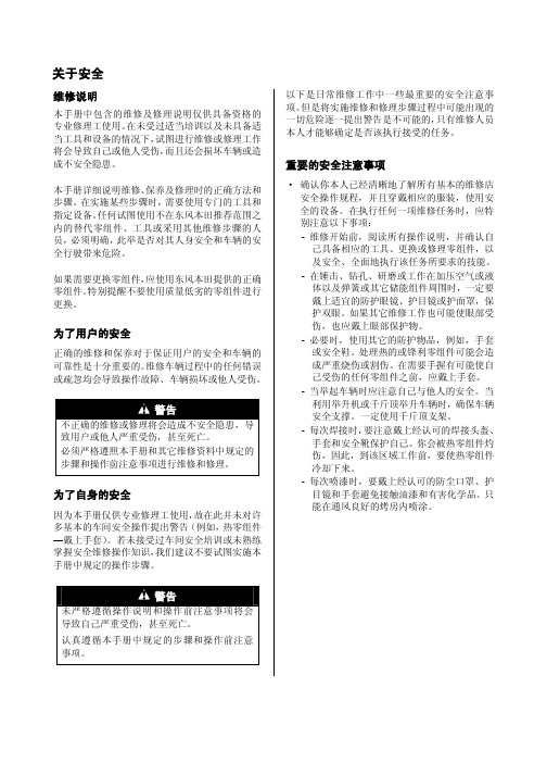
关于安全维修说明本手册中包含的维修及修理说明仅供具备资格的专业修理工使用。
在未受过适当培训以及未具备适当工具和设备的情况下,试图进行维修或修理工作将会导致自己或他人受伤,而且还会损坏车辆或造成不安全隐患。
本手册详细说明维修、保养及修理时的正确方法和步骤。
在实施某些步骤时,需要使用专门的工具和指定设备。
任何试图使用不在东风本田推荐范围之内的替代零组件、工具或采用其他维修步骤的人员,必须明确,此举是否对其人身安全和车辆的安全行驶带来危险。
如果需要更换零组件,应使用东风本田提供的正确零组件。
特别提醒不要使用质量低劣的零组件进行更换。
为了用户的安全正确的维修和保养对于保证用户的安全和车辆的可靠性是十分重要的。
维修车辆过程中的任何错误或疏忽均会导致操作故障、车辆损坏或他人受伤。
警告不正确的维修或修理将会造成不安全隐患,导致用户或他人严重受伤,甚至死亡。
必须严格遵照本手册和其它维修资料中规定的步骤和操作前注意事项进行维修和修理。
为了自身的安全因为本手册仅供专业修理工使用,故在此并未对许多基本的车间安全操作提出警告(例如,热零组件—戴上手套)。
若未接受过车间安全培训或未熟练掌握安全维修操作知识,我们建议不要试图实施本手册中规定的操作步骤。
警告未严格遵循操作说明和操作前注意事项将会导致自己严重受伤,甚至死亡。
认真遵循本手册中规定的步骤和操作前注意事项。
以下是日常维修工作中一些最重要的安全注意事项。
但是将实施维修和修理步骤过程中可能出现的一切危险逐一提出警告是不可能的,只有维修人员本人才能够确定是否该执行接受的任务。
重要的安全注意事项 · 确认你本人已经清晰地了解所有基本的维修店安全操作规程,并且穿戴相应的服装,使用安全的设备。
在执行任何一项维修任务时,应特别注意以下事项:- 维修开始前,阅读所有操作说明,并确认自己具备相应的工具、更换或修理零组件,以及安全、全面地执行该任务所要求的技能。
- 在锤击、钻孔、研磨或工作在加压空气或液体以及弹簧或其它储能组件周围时,一定要戴上适宜的防护眼镜、护目镜或护面罩,保护双眼。
2015 Honda Fit 新型车身维修信息说明书
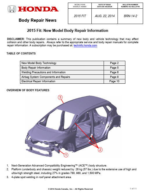
OVERVIEW OF BODY FEATURES1.Next-Generation Advanced Compatibility Engineering™ (ACE™) body structure.2.Platform (underbody and chassis) weight reduced by 26 kg (57 lbs.) due to the extensive use of high andultra-high strength steel, including 27% in grades 780, 980, and 1,500 MPa. 3.4-plate spot welding in roof panel attachment area.DISCLAIMER: This publication contains a summary of new body and vehicle technology that may affect collision and other body repairs. Always refer to the appropriate service and body repair manuals for complete repair information. A subscription may be purchased at: 2015 Fit: New Model Body Repair InformationTABLE OF CONTENTSNew Model Body TechnologyPage 2Body Repair InformationPage 5 Welding Precautions and Information Page 6 Airbag System Components and Repairs Page 8 Electrical Repair InformationPage 101 23 Body Repair NewsMODEL/YEAR MODÈLE /ANNÉE DATE OF ISSUE DATE EN VIGUEUR BULLETIN NUMBER NUMÉRO DU BULLETIN2015 FIT AUG. 22, 2014 BRN-14-2BODY CONSTRUCTION AND HIGH STRENGTH STEEL CONTENT•Steel parts are color-coded based on their tensile strength in mega-Pascals (MPa). •High strength steel is defined as any steel with a tensile strength of 340 MPa or higher.•Steel repair and welding procedures vary depending on the tensile strength of the parts involved.New Model Body Technology980 MPa 590 MPa440 MPa 1,500 MPa780 Mpa 270 MPa Steel Tensile Strength LegendThese illustrations are for general reference only. Some body parts are constructed from multiple layers of different tensile strength steels. Always refer to the body repair manual body construction section for specific steel tensile strength information.Important Information Lower ViewNote: 1,500 MPa Steel Reinforcement Inside Center PillarUpper View1,500 MPa (HOT STAMP) STEEL LOCATIONS1,500 MPa steel is stronger than ordinary steel, so it can help protect vehicle occupants while reducing overall vehicle weight to improve fuel efficiency.The numbered parts in the diagram below are constructed of 1,500 MPa steel:123All Fit Models1 Front Pillar Upper Stiffener2 Center Pillar Reinforcement3 Side Sill StiffenerLIFTING AND TOWING PRECAUTIONS•Flat bed towing equipment is the preferred method to transport this vehicle.•Front wheel lift towing equipment may also be used to tow this vehicle.For more information, refer to “Emergency Towing” inthe owner’s manual.•Lift or jack only at the specified points to avoid damaging the vehicle.•Do not lift or tow this vehicle by its bumpers, or serious damage will result.For more information, refer to “Lift and Support Points” in the service or body repair manual.4-PLATE SPOT WELDED ROOF PANEL ATTACHMENTThe body of this vehicle is assembled using new technology that welds the entire inner framework before the pre-welded outer body panels are attached. This creates a unique 4-plate spot weld at the roof panel side flanges.•Squeeze-type resistance spot welding (STRSW) is the required repair method because one of the 4 plates is constructed of 980 and 1,500 MPa steel (depending on location).•Any squeeze-type resistance spot welder meeting the specifications published in the body repair manual can make this 4-plate spot weld.•Refer to body repair manual section “Roof Panel Removal and Installation” for complete information.Roof Panel 4-Plate Spot Weld Area(980/1,500 MPa)No Spot Welds Roof Panel Section A - ARear Wheel Arch AreaREAR WHEEL ARCH FLANGE – NO SPOT WELDSThe rear wheel arch flange uses a new narrower design that eliminates spot welds to improve appearance. •The flange is attached and sealed using adhesive (3M AUTO MIX Panel Bonding 8115, or equivalent) •Refer to body repair manual section “Rear Side Outer Panel Removal and Installation” for complete information.Body Repair InformationUSE OF HEAT DURING BODY STRAIGHTENING AND REPAIR When you are doing body straightening and repair procedures: •DO NOT apply heat to any body part during straightening. This may compromise the internal structure and strength of high-strength steel parts.•Any part that has heat applied to it during straightening MUST be replaced with new parts.•Ignoring these instructions may significantly reduce occupant protection in any subsequent collision.SECTIONING (CUT AND JOINT) GUIDELINESVarious high-strength steel materials with different sheet thicknesses and strengths are applied in many places that vary by body design in order to increase collision safety performance, body stiffness, and weight reduction.Stiffening members inside each part (patch, stiffener, etc.) are also specified in detail.Follow these guidelines to avoid an unsafe repair:•Avoid sectioning (cut and joint) except for outer panels and floor panels unless a specific procedure is provided in the body repair manual.•However, depending on the type of vehicle damage, steel parts with a tensile strength ≤ 780 MPa may be sectioned (cut and weld) under the following conditions:– Sectioning must be done in a single-layer area of the part. – Multi-layer internal steel reinforcements and stiffeners must not be cut.– The repair is not in a load bearing area such as engine, transmission, or suspension mounting points.•Replace body structural components such as stiffeners, reinforcements, and other multi-layeredsteel parts as assemblies that match the replacementparts configuration. •Approved welding methods are listed in the table.•Refer to the body repair manual for complete information.NOTE: The following content is intended only to highlight new/special concerns. No body repairs should be attempted without first referencing the appropriate body repair manual for complete information.Steel Part Tensile Strength (MPa) Welding MethodSpot Weld MAG Welding Plug Butt<590590 780 980 X 1500XXWelding Methods For Steel Parts( = Approved X = Not Approved)Sectioning Area ExamplesWelding Precautions and Information REPAIRING 1,500 MPa STEEL PARTSObserve these precautions when repairing 1,500 MPa steel parts: •NEVER attempt to straighten damaged 1,500 MPa steel parts because they may crack.•1,500 MPa steel parts MUST be replaced at factory seams using squeeze-type resistance spot welding(STRSW).•MIG brazed joints should be used ONLY in locations not accessible by a spot welder.•To assure adequate weld tensile strength, always set the spot welder to the specifications provided inthe body repair manual.Important InformationParts made of Ultra High Strength Steel(UHSS/1,500MPa/ USIBOR) and must be installed asa complete part. No sectioning allowed. Ultra HighStrength Steel requires special welding equipment,procedures and settings. See the welding section ofthe appropriate body repair manual. Failure to use theproper equipment or follow the proper procedures canresult in an unsafe repair.•NEVER perform MAG welding on 1,500 MPa steel.The heat generated during welding will significantlyreduce the strength and structural integrity of1,500 MPa steel parts.•This photo shows tensile strength test results ofwelded 1,500 MPa steel. The 1,500 MPa steel fracturedfirst, because the welding heat reduced its strength tofar below 590 MPa.•For more information, refer to “Hot Stamp (1,500 MPa) Parts Welding Specifications” in the body repair manual.MIG BRAZING GUIDELINES FOR 1,500 MPa STEEL PARTS Refer to the body repair manual for complete information:•MIG brazed joint locations are specified in the body repair manual.• A single or double hole MIG braze may be specified in the body repair manual depending on the tensilestrength of the parts being joined.•The size and number of holes is critical to achieving adequate joint strength.• A pulsed MIG welder MUST be used. Refer to the equipment manufacturer’s instructions for weldervoltage and current setup.•Photos at right show the difference in resultsbetween pulsed and non-pulsed MIG brazing.MAG WELDING SPECIFICATIONS FOR 590-980 MPa HIGH-STRENGTH STEEL PARTS NOTE: In this publication and the body repair manuals,gas metal arc welding (GMAW) is referred to by itssubtypes depending on the welding/brazingrequirements:•MIG welding/brazing = Metal inert gas welding orbrazing where 100% argon (Ar) shielding gas isused. Argon is inert and does not react with themolten weld pool or brazing operation.•MAG welding = Metal active gas welding wherethe shielding gas being used contains a mixture of80% argon (Ar) and 20% carbon dioxide (CO2).It is considered active because the CO2 undergoesa limited reaction with the molten weld pool.The body repair manual specifies the weld types and locations for each body panel:•The welding wire used must have a tensile strength equal to, or greater than, the lowest tensile strength of the parts being welded. This conversion chartshows the relationship of steel tensile strength (MPa) to the minimum welding wire tensile strength (ksi). •Refer to the diagrams shown below:Steel Tensile (MPa) Wire Tensile (ksi)590 ≥86780 ≥113980 ≥142(1,000 psi = 1 ksi) Certain parts made of High Strength Steel (590-980 MPa) must be installed as a complete part. Refer to “Parts Sectioning (Cut and Joint) Guidelines” in the body repair manual for complete information.High-strength steel requires special welding equipment, procedures, and settings. See the welding section of the appropriate body repair manual. Failure to use the proper equipment or follow the proper procedures can result in an unsafe repair.Important InformationMAG PLUG WELDING GUIDELINES•MAG plug welding may be done when joining body components to 590-980 MPa steel parts.•Follow the recommendations described in the body repair manual section “MAG Welding Conditionsfor High-Strength Steel (Except 1,500 MPa) Parts.” MAG BUTT WELDING GUIDELINES•MAG butt welding may only be done on steel parts with a tensile strength of 780 MPa and lower. •Welding speed is critical to achieve the correct weld strength and minimize the heat affected zone (HAZ). •Follow the recommendations described in the body repair manual section “MAG Welding Conditionsfor High-Strength Steel (Except 1,500 MPa) Parts.”SmartVent Side AirbagAIRBAG SYSTEM COMPONENTSThe airbag system in this vehicle includesthe following components that may deploy in a collision:1.Driver and front passenger seat belt tensioners(may deploy independently from any airbags). 2.Driver and front passenger SRS airbags. 3.Side airbags mounted in the outer driver andfront passenger seat-backs.4.Side curtain airbags mounted above the leftand right side windows under the headliner.SMARTVENT™ SIDE AIRBAGSThis vehicle is equipped with SmartVent side airbag construction: •This airbag design helps mitigate the risk of excessive airbag deployment force and risk of injury to smaller seat occupants. •Eliminates the need for the Occupant Position Detection System (OPDS ) sensor located in the front passenger’s seat-back.As with all side airbags, the following service precautions apply: •Special seat covers and/or breakaway thread are used. to ensure proper deployment path.•Damaged front seat covers should be replaced, not repaired. •Do not install non-factory seat covers, because they may alter the airbag's intended deployment path.Airbag System Components and Repairs3421AIRBAG SYSTEM INDICATORSThere are two indicators used for the airbag system:Supplemental Restraint System (SRS) IndicatorWhen you turn the vehicle to the ON mode, this indicator should come on and then turn offafter about 6 seconds.•If the SRS indicator does not go off, or does not come on at all,there is a problem with the system.•DTCs must be read and cleared using the HDS (or equivalent)scan tool. Contact a Honda dealer for assistance if necessary.•If a vehicle is sent to the dealer for airbag system repair ortroubleshooting, include a copy of the repair estimate with partnumbers and the source for any replaced airbag system parts.Passenger Airbag OFF IndicatorThe indicator comes on to alert you that the passenger’s front airbag has been turned off.•This occurs when the front passenger’s weight sensors detectabout 29 kg (65 lbs.) or less, the weight of an infant or small child,on the seat.•If the indicator comes on with no front passenger and no objectson the seat, or with an adult occupying the seat, something maybe interfering with the seat weight sensors, or there may be aproblem with the system. Contact a Honda dealer for assistanceif necessary.AIRBAG SYSTEM REPAIRS REQUIRED AFTER DEPLOYMENTTo restore proper function and allow DTCs to be cleared, the airbag system MUST be repaired as specified in the service manual. Refer to “Component Replacement/Inspection After Deployment” for complete information. •DO NOT install used, refurbished, or modified airbag system parts!•When making airbag system repairs, only use new genuine replacement parts, which are manufactured to the same standards and quality as the original parts.•To ensure the correct replacement airbag system parts are installed, provide the vehicle’s VIN when ordering parts. Compare the part numbers on the new and removed parts to make sure they match. AIRBAG SYSTEM ELECTRICAL REPAIRSExcept when doing electrical inspections that require battery power, always turn the vehicle to the OFF (LOCK) mode, disconnect the negative battery cable, then wait at least 3 minutes before starting work.•For easier identification, electrical connectors that contain onlyairbag system wiring are yellow in color.•Many harnesses that contain primarily airbag wiring are alsowrapped in yellow tape.•Airbag system wiring that runs in a common harness, such as afloor harness, is generally not marked.•NEVER attempt to modify, splice, or repair airbag system wiring.If any part of the airbag system wiring is damaged, replace theaffected wiring harness(es).NOTE: Refer to the service manual for complete restraintsystems operation, diagnostic, and repair information.REPLACEABLE HEADLIGHT BRACKETSIf any of the headlight assembly attachment brackets are broken, service replacement brackets are available as service parts.A broken headlight assembly can be repaired usingservice brackets provided it meets the following criteria:•No damage to the headlight assembly•Sealing of the headlight lens and headlight housingis maintained.These service brackets are available:1.Upper front bracket2.Upper rear bracket3.Lower bracketRefer to “Headlight Bracket Replacement” in the body repair manual for complete information. 123 Service Headlight BracketsSYSTEMS THAT MAY REQUIRE DEALER ASSISTANCE WITH AIMINGSome models may be equipped with one or more of the following systems that require aiming after collision repairs. Special tools are required to complete the aiming procedures. Contact a Honda dealer for assistance. LaneWatch™:LaneWatch uses a camera and the center display to help drivers recognize objects in the blind spot of the passenger side door mirror.The LaneWatch camera must be aimed after one or more of the following procedures are done: •LaneWatch camera removal or replacement•Door mirror removal or replacement•Door panel removal or replacement•Door panel body repairLaneWatch does not set DTCs. Troubleshooting and camera aimingare done using the navigation system or center display self-diagnostics.LaneWatch doesn’t use an indicator to inform the driver of a malfunction.Electrical Repair InformationELECTRICAL GROUND WIRE PROTECTION•Painting over electrical ground locations may causeelectrical systems, such as Vehicle Stability Assist(VSA), to malfunction and set DTCs that may bedifficult to diagnose.•Protect the ground wire and the ground wire mountinghole threads with a bolt or silicone plug when primingor painting.。
广本飞度轿车空调系统及其检修(二)
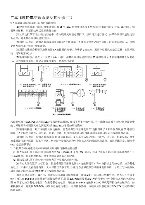
广本飞度轿车空调系统及其检修(二)2.2冷凝器风扇(电动机)电路的故障检修(1)检查发动机罩下熔丝/继电器盒内的11号(20A)熔丝和仪表板下熔丝/继电器盒内的l号(7.5A)熔丝。
如果熔丝熔断,则更换熔丝后重新进行检查。
(2)从发动机罩下熔丝/继电器盒中,将冷凝器风扇继电器拆下,然后对其进行测试。
如果冷凝器风扇继电器不正常,则更换冷凝器风扇继电器。
(3)如图4a所示,测量冷凝器风扇继电器5P连接器端子2和车身搭铁之间的电压。
应为蓄电池电压。
否则更换发动机罩下熔丝/继电器盒。
(4)用跨接线把冷凝器风扇继电器5P连接器的端子1和端子2连起来,观察冷凝器风扇是否运转,如果不运转。
则转到第(6)步。
(5)断开跨接线,将点火开关置于0N(Ⅱ)位,测量冷凝器风扇继电器5P连接器端子5和车身搭铁之间的电压,应为蓄电池电压。
如果是蓄电池电压。
则维修冷凝器风扇继电器与ECM/PCM之间绿(GRN)导线的断路故障;如果不是蓄电池电压。
贝4维修仪表板下熔丝/继电器盒中的1号熔丝和冷凝器风扇之间的黑/黄(BLK/YEL)导线的断路故障。
(6)断开跨接线。
断开冷凝器风扇连接器。
检查冷凝器风扇继电器5P连接器端子l和冷凝器风扇2P连接器的端子2之间的导通性,应导通。
如果不导通,则维修冷凝器风扇继电器和冷凝器风扇问导线的断路故障。
(7)如图4b所示,检查冷凝器风扇2P连接器的端子l与车身搭铁之间的导通性。
应导通。
如果导通,则更换冷凝器风扇电阻器;如果不导通。
则检查冷凝器风扇和车身搭铁之间的导线断路故障,如果导线正常。
则检查G301是否搭铁不良。
2.3散热器(风扇电动机)和冷凝器风扇通用电路的故障检修(1)检查发动机罩下熔丝/继电器盒内的lO号(20A)和11号(20A)熔丝,以及仪表板下熔丝/继电器盒内的1号(7.5A)熔丝。
如果熔丝熔断。
则更换熔丝后重新进行检查。
(2)拆除发动机罩下熔丝/继电器盒内的冷凝器风扇继电器。
(3)将点火开关置于ON(Ⅱ)位。
广州本田锋范原厂维修手册

燃油和排放系统11-38系统说明(续)进气歧管调节(IMT)阀系统通过打开和关闭进气歧管调节(IMT)作动器调节发动机动力。
如果阀门关闭,发动机转速低时扭矩高。
如果阀门打开,发动机转速高时扭矩高。
进气歧管调节(IMT)作动器有一个检测IMT 阀位置并将其发送到PCM的传感器。
废气再循环(EGR)系统图EGR系统使再循环废气通过EGR管和进气歧管进入燃烧室以降低氮氧化物(NOx)的排放。
使废气通过EGR管以防止进气歧管和节气门体上形成积碳。
PCM存储器包含适用于不同工作条件的EGR阀的理想位置。
EGR阀位置传感器检测EGR阀的升程并将其传送至PCM。
然后,PCM将其与存储器中的理想升程相比较(基于其他传感器发出的信号)。
如果两者不同,PCM即切断通向EGR阀的电流。
11-39燃油和排放系统11-40系统说明(续)蒸发排放(EVAP)控制图EVAP 控制系统使排放到大气的燃油蒸汽量最小。
来自燃油箱的燃油蒸汽暂时存储于EVAP 碳罐中,直至净化时,燃油蒸汽从EVAP 碳罐进入发动机进行燃烧。
•通过向碳罐内注入新鲜空气以净化EVAP 碳罐,然后将油气注入进气歧管端口。
•净化真空由EVAP 碳罐净化阀控制。
每当发动机冷却液温度高于60 °C (140 °F)时,该阀门即打开。
•当燃油箱中的蒸汽压力高于EVAP 双通阀设定的值时,阀门打开并调节燃油蒸汽到EVAP碳罐的流量。
PCM电路图11-41燃油和排放系统11-42系统说明(续)PCM 电路图(续)(续)11-43燃油和排放系统11-44系统说明(续)PCM 电路图(续)(续)11-45燃油和排放系统11-46系统说明(续)PCM 电路图(续)(续)11-47燃油和排放系统11-48系统说明(续)PCM 电路图(续)(续)11-49燃油和排放系统11-50系统说明(续)PCM 电路图(续)11-51燃油和排放系统11-52系统说明(续)PCM 电路图(续)11-53注意:•带阳端子的插接器(双轮廓线):从端子侧看•带阴端子的插接器(单轮廓线):从线束侧看*:插座(单框线)插接器:从端子侧看(续)燃油和排放系统11-54系统说明(续)PCM 电路图(续)11-55注意:•带阳端子的插接器(双轮廓线):从端子侧看•带阴端子的插接器(单轮廓线):从线束侧看(续)燃油和排放系统11-56系统说明(续)PCM 电路图(续)11-57注意:•带阳端子的插接器(双轮廓线):从端子侧看•带阴端子的插接器(单轮廓线):从线束侧看*:插座(单框线)插接器:从端子侧看PGM-FI 系统部件位置索引11-5811-59PGM-FI 系统11-60DTC 故障排除DTC P0102:MAF 传感器电路低电压注意:进行故障排除前,记录所有定格数据和所有车载快照,并查看一般故障排除信息(参见第11-9页)。
2004飞度维修手册
2004飞度维修手册2004飞度维修手册第一章:车辆介绍(500字)飞度是2004年本田汽车推出的一款小型家用车型。
它采用了前置前驱的设计,车身尺寸紧凑,适合城市驾驶。
本章将介绍飞度的主要技术参数和车身结构,帮助读者对车辆有一个整体的认识。
1.1 技术参数飞度的整车长度为3810mm,整车宽度为1675mm,整车高度为1525mm。
轴距为2450mm,最小离地间隙为160mm。
它采用了前麦弗逊式独立悬架和后非独立整体桥式悬架,前轮采用了盘式刹车,后轮采用了鼓式刹车。
动力系统是一台排量为1.3L的汽油发动机,最大功率为73kW,最大扭矩为119Nm。
1.2 车身结构飞度的车身采用了四门五座的设计,具有较强的运载能力。
车身采用了高强度钢材制作,具有较好的刚性和抗冲击性能。
车门的开启方式为传统的拉手式,后备厢容积为350L,可以满足日常使用的需求。
整车的外饰设计简洁大方,具有较好的空气动力学性能。
第二章:常见故障及排查方法(1500字)飞度作为一款老款车型,由于车龄较长,常见故障也相对较多。
本章将介绍飞度常见故障的排查方法,并提供相应的解决方案。
2.1 发动机无法启动可能原因:1) 点火系统故障:检查火花塞、点火线圈等点火系统部件是否正常工作。
2) 燃料供给问题:检查燃油泵、燃油滤清器等燃油供给系统部件是否正常工作。
3) 电池电量不足:检查电池电量是否充足。
4) 空燃比问题:检查进气系统是否存在堵塞或漏气情况。
解决方法:1) 检修点火系统,更换损坏的点火系统部件。
2) 检修燃油供给系统,更换损坏的部件。
3) 充电或更换电池。
4) 清洁或更换堵塞的进气系统部件。
2.2 发动机噪音异常可能原因:1) 气缸垫片磨损:检查气缸垫片是否需要更换。
2) 按摩杆磨损:检查按摩杆是否需要更换。
3) 摩擦件磨损:检查摩擦件是否需要更换。
4) 配气机构磨损:检查配气机构是否需要更换。
解决方法:1) 更换磨损的气缸垫片。
2) 更换磨损的按摩杆。
2017-2018 Honda Clarity 车身维修信息手册说明书
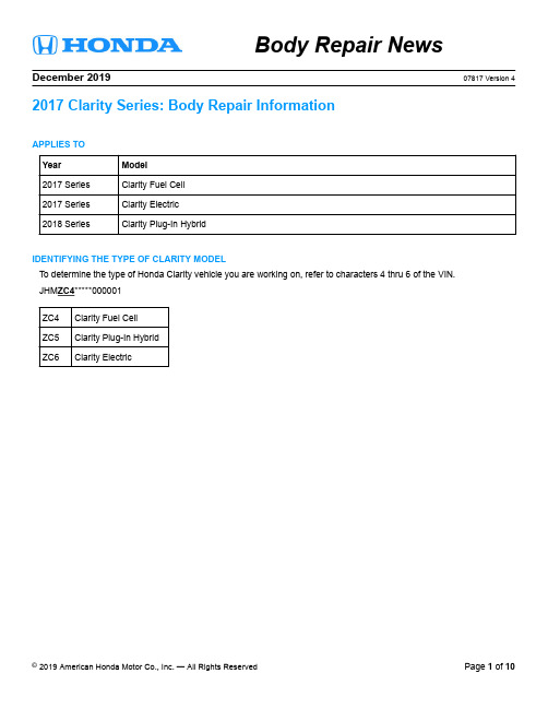
Body Repair NewsDecember 201907817 Version 4 2017 Clarity Series: Body Repair InformationAPPLIES TOYear Model2017 Series Clarity Fuel Cell2017 Series Clarity Electric2018 Series Clarity Plug-In HybridIDENTIFYING THE TYPE OF CLARITY MODELTo determine the type of Honda Clarity vehicle you are working on, refer to characters 4 thru 6 of the VIN.JHM ZC4*****000001ZC4Clarity Fuel CellZC5Clarity Plug-In HybridZC6Clarity ElectricOVERVIEW OF BODY FEATURES•Advanced Compatibility Engineering™ (ACE™) body structure•The same basic body platform supports three electric-powered model variations•Body construction using 52% lightweight materials, including aluminum and ultra-high-strength steel (UHSS - 980 MPa and higher)•World’s first Glass Fiber Reinforced Polymer/Plastic (GFRP) rear bumper beam•Bolt-on resin composite front bulkhead assemblyBODY TECHNOLOGYBODY CONSTRUCTION AND HIGH-STRENGTH STEEL CONTENT•Steel parts are color coded based on their tensile strength in megapascals (MPa).•High-strength steel (HSS) is defined as any steel with a tensile strength of 340 MPa or higher.•Ultra-high-strength steel (UHSS) is defined as any steel with a tensile strength of 980 MPa or higher.•Steel repair and welding procedures vary depending on the tensile strength of the parts involved.These illustrations are for general reference only. Some body parts are constructed from multiple layers of different tensile strength steels. Always refer to the body repair manual body construction section for specific steel tensile strength information.ALUMINUM PARTS & REPAIRABILITYThe following parts are made from aluminum alloy:•Front Bumper Beam•Hood Panel•Front Fenders•Front and Rear Doors•Rear Shelf Panels•Trunk Lid•Front and Rear Subframe (Not Shown)1,500 MPa (HOT STAMP) STEEL LOCATIONS1,500 MPa steel is stronger than ordinary steel, so it can help protect vehicle occupants while reducing overall vehicle weight to improve fuel efficiency.The following numbered parts are constructed of 1,500 MPa steel:1.Front Inner Upper Panel2.Front Pillar Upper Stiffener3.Front Side Frame Extension4.Front Pillar Lower Stiffener5.Side Sill Reinforcement6.Center Pillar Upper Stiffener7.Rood Side Stiffener8.Floor Crossmember Stiffener1,500 MPa stiffeners are located inside the front floor frame, front floor crossmember, and front floor rear crossmember.RESIN COMPOSITE (PLASTIC) FRONT BULKHEADThis vehicle has a lower bulkhead assembly constructed of resin composite material.•The bulkhead design improves engine compartment access during factory assembly and service.•The front bulkhead is attached with multiple bolts and is sold and replaced only as a complete assembly.•The cooling fans, radiator, A/C condenser, hood lock, outside air temperature sensor, and related piping/ components are attached to the front bulkhead.•Over-torquing or using power tools may break these inserts loose, requiring front bulkhead replacement.• A damaged bulkhead must be replaced, not repaired.•For more information, refer to the Front Bulkhead Replacement section in the service information.LASER-BRAZED ROOF ATTACHMENTThe factory roof panel is attached using a laser-brazed joint to the outer side panels.•Laser-brazed joints cannot be duplicated during roof panel replacement.•The original roof panel must be cut off near the lazer-brazed joint, and the remaining flange must be removed separately.•The service roof panel is attached using service replacement bolted clamp-type brackets (5 each side) and panel bonding adhesive.•The roof panel, service brackets, and bolts must be ordered separately. Refer to the online parts catalog.•Refer to the Roof Panel Replacement section in the body repair manual.BEFORE STARTING COLLISION REPAIRSWith any collision repairs, always refer to and follow the information outlined in the Generation Information section of the body repair manual. The following information outlines special consideration when repairing a Honda Clarity vehicle. IPU (Intelligent Power Unit) Leak Test After Airbag DeploymentThis unit applies to the following vehicles:•Clarity Electric•Clarity Plug-In HybridAn IPU leak test must be done on any Clarity Electric or Clarity Plug-In Hybrid involved in a collision severe enough to deploy the airbags. This test consists of pressurizing the IPU with shop air to check for any leaks. If the IPU fails the leak test, it must be replaced.The Clarity Electric has a front and rear IPU. Both of these units must be tested. If you have a vehicle with deployed airbags, take it to an authorized Honda dealer to have this test done before starting any repairs.High-Voltage System ComponentsThese components apply to the following vehicles:•Clarity Electric•Clarity Plug-In Hybrid•Clarity Fuel CellIf you are doing any repairs that require the removal of high-voltage system components, the vehicle must be taken to an authorized Honda dealer. Authorized Honda dealers have the training and equipment needed to remove and install high-voltage components.Refer to the Electrical Powertrain Component Location Index in the service information for a complete list of high-voltage system components.Hydrogen System/Fuel Cell System ComponentsThese components apply to the Clarity Fuel CellAccording to the California Fire Code, the hydrogen level in the hydrogen tanks must be less than 0.5 kg before the vehicle is brought inside the shop for repairs related to the hydrogen system. These rules do not apply to service/repair of non-hydrogen system components and collision repairs as long as no repairs involving welding or open flame are done and the hydrogen system components are not involved.If you are doing any repairs that involve any hydrogen system or fuel cell system-related components or involve welding or open flame, the vehicle must be taken to an authorized Honda Clarity Fuel Cell dealer. For a list of authorized Honda Clarity Fuel Cell dealers, refer to page 10.Refer to the Fuel Cell System Component Location Index in the service information for a complete list of hydrogen/fuel cell system components.DURING COLLISION REPAIRSWith any collision repairs, always refer to and follow the information outlined in the General Information section of the body repair manual. The following information outlines special precautions when repairing a Honda Clarity. Precautions When Using a Heated Paint BoothSystem PrecautionsSRS•Do not apply heat greater than 212°F (100°C) when drying painted surfacesanywhere around the SRS components.Fuel Cell•When drying paint in a heated paint booth, cover the air intake duct, exhaust pipe,and ventilation ducts with tape. Refer to the Fuel Cell System Component LocationIndex in the service information for the location of these components.•High temperature may damage the fuel cell (FC) stack and the compressedhydrogen gas (CHG) tank. When drying paint in a heated paint booth, make sure thetemperature does not exceed 149°F (65°C).Electric Powertrain•High temperature may damage the battery module. When drying paint in a heatedpaint booth, make sure the temperature does not exceed 149°F (65°C).AFTER COLLISION REPAIRSCollision Shut-off History Clear CommandWhen the battery condition monitor module receives a collision detection signal (CDS) from the SRS unit or the H2 (hydrogen) shut-off unit (Clarity Fuel Cell only), it updates the collision shut-off history and stores it in the module’s nonvolatile memory. The battery condition monitor module stops supplying power to the high-voltage circuits, disrupting the control signal to be sent to the high-voltage contactor inside the battery module the next time the system is being turned on.The battery condition monitor module also stops supplying hydrogen to the fuel cell (FC) stack by turning the FC cut relay at the same time. To resume power supply to the high-voltage circuits and hydrogen supply to the FC stack, the collision shut-off history must be cleared.AUTHORIZED HONDA CLARITY DEALERSThe Clarity Electric and Clarity Plug-In Hybrid can be taken to any Honda dealer for service and repairs. To locate an authorized Honda dealer, contact Honda Customer Service at (800) 999-1009.Clarity Fuel Cell repairs should be done only by Authorized Clarity Fuel Cell dealers. For a list of authorized Clarity Fuel Cell dealers, see below.Southern CaliforniaCity Dealer Name Telephone NumberCerritos Norm Reeves Honda Superstore(888) 849-4466Culver City Culver City Honda(424) 298-4875Irvine Norm Reeves Honda Superstore Irvine(888) 721-4053Pasadena Honda of Pasadena(866) 788-5832Torrance Scott Robinson Honda(855) 725-2211Woodland Hills Woodland Hills Honda(800) 494-1164Northern CaliforniaCity Dealer Name Telephone NumberColma Honda of Serramonte(888) 892-5396Dublin Dublin Honda(877) 412-7199Oakland Honda of Oakland(800) 352-1859Palo Alto Anderson Honda(650) 843-6041Roseville AutoNation Honda Roseville(916) 467-8056San Jose Honda of Stevens Creek(855) 357-6146。
本田车身修复手册-焊接和切割指南修订版说明书
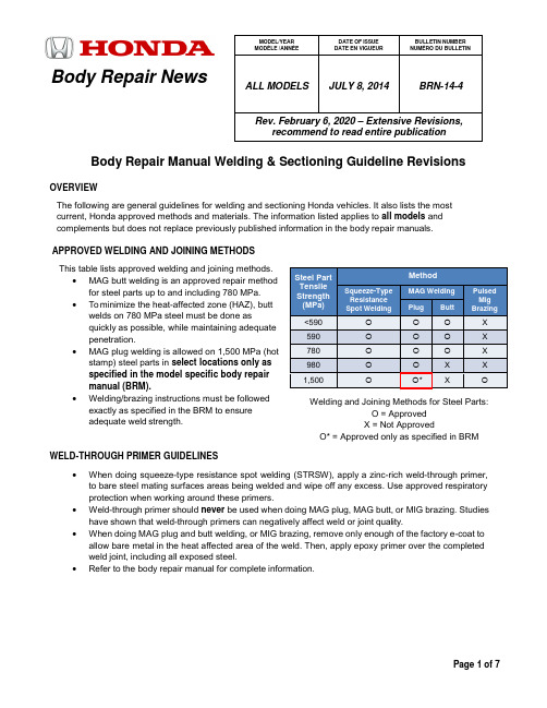
Body Repair NewsBody Repair Manual Welding & Sectioning Guideline RevisionsOVERVIEWThe following are general guidelines for welding and sectioning Honda vehicles. It also lists the most current, Honda approved methods and materials. The information listed applies to all models and complements but does not replace previously published information in the body repair manuals.APPROVED WELDING AND JOINING METHODS This table lists approved welding and joining methods.• MAG butt welding is an approved repair methodfor steel parts up to and including 780 MPa. • To minimize the heat-affected zone (HAZ), buttwelds on 780 MPa steel must be done asquickly as possible, while maintaining adequate penetration.• MAG plug welding is allowed on 1,500 MPa (hotstamp) steel parts in select locations only as specified in the model specific body repair manual (BRM).• Welding/brazing instructions must be followedexactly as specified in the BRM to ensure adequate weld strength.WELD-THROUGH PRIMER GUIDELINES•When doing squeeze-type resistance spot welding (STRSW), apply a zinc-rich weld-through primer, to bare steel mating surfaces areas being welded and wipe off any excess. Use approved respiratory protection when working around these primers.• Weld-through primer should never be used when doing MAG plug, MAG butt, or MIG brazing. Studies have shown that weld-through primers can negatively affect weld or joint quality.•When doing MAG plug and butt welding, or MIG brazing, remove only enough of the factory e-coat to allow bare metal in the heat affected area of the weld. Then, apply epoxy primer over the completed weld joint, including all exposed steel.•Refer to the body repair manual for complete information.MODEL/YEAR MODÈLE /ANNÉE DATE OF ISSUE DATE EN VIGUEUR BULLETIN NUMBER NUMÉRO DU BULLETINALL MODELS JULY 8, 2014 BRN-14-4Rev. February 6, 2020 – Extensive Revisions,recommend to read entire publicationSteel Part Tensile Strength (MPa) MethodSqueeze-Type Resistance Spot WeldingMAG Welding Pulsed Mig BrazingPlugButt<590 X 590 X 780 X 980 X X 1,500*XWelding and Joining Methods for Steel Parts:O = Approved X = Not ApprovedO* = Approved only as specified in BRMMAG WELDING WIRE SELECTION GUIDELINES•Welding wire used during high-strength-steel repair must have a tensile strength equal to or greater than the lowest tensile strength of the parts being welded.•Typical ER70S-6 wire has a minimum tensile strength of 70 ksi (483 MPa). This wire can be used when welding up to 440 MPa steel parts.• This table shows the relationship of steel tensile strength (MPa) to the minimum welding wire tensile strength (ksi).HIGH-STRENGTH MAG WELDING WIREThe following are approved high-strength-steel welding wires:• Bohler Union X96Bohler Union X96Honda Tools & Equipment Program 1-866-868-3372Pro Spot https://Chief AutomotiveAuthorized Chief Automotive Canadian DistributorNOTES:• Bosch DS980J solid welding wire is no longer available but can still be used.•Wire has a size of 0.8 mm (0.030 inch) in diameter and is used for welding joints in high-strength steel of 590 MPa and higher. It may be used for welding lower grade steel, but it is not necessary to provide the required strength.1,500 MPA ULTRA-HIGH-STRENGTH (HOT STAMPING) WELDING CONDITIONSFor an explanation of 1,500 MPa ultra-high-strength (Hot Stamping) steel sheets, refer to the section, Ultra-High- Strength Steel Sheets 1,500MPa grade (hot stamping) in the body repair basics manual. Removal of Aluminum Coating1,500 MPa hot stamp steel sheets have a 10-micron aluminum coating that must be removed (sanded off) from the weld zone of the panel before welding. Both exterior and mating surfaces require the removal of coating. Failure to do so will create a weak weld and ultimately a failure of the joint. NOTE:It is only necessary to sand down the area to be welded.590>86780 >113 980>142(1,000 psi = 1 ksi)SPOT WELDING CONDITIONS FOR 1,500 MPA ULTRA HIGH-STRENGTH STEEL PARTSWhen spot-welding 1,500 MPa steel parts, you must manually set the welder to the conditions listed below. The required welding conditions will be noted in the model specific body repair manual.NOTE:For the actual settings of the welder, refer to the specifications supplied by the welder manufacturer.1 6500 300 2452 (250) 17 8500 700 3432 (350)2 7000 300 2452 (250) 18 9000 700 3432 (350)3 7500 300 2452 (250) 19 9500 700 3432 (350)4 6500 400 2942 (300) 20 8500 800 3432 (350)5 7000 400 2942 (300) 21 9000 800 3432 (350)6 7500 400 2942 (300) 22 9500 800 3432 (350)7 8000 400 2942 (300) 23* 10500 700 3432 (350)8 7000 500 3432 (350) 24* 10500 800 3432 (350)9 7500 500 3432 (350) 25* 8000 1500 3432 (350)10 8000 500 3432 (350) 26* 8000 800 3432 (350)11 8500 500 3432 (350) 27 8500 1500 3432 (350)12 7500 600 3432 (350) 28 7500 800 3432 (350)13 8000 600 3432 (350) 29 8000 1200 3432 (350)14 8500 600 3432 (350) 30 8500 1200 3432 (350)15 9000 600 3432 (350) 31 9000 1200 3432 (350)16 8000 700 3432 (350)NOTES:•Condition numbers with an asterisk are currently not used by any Honda models at the time of this publication.•The condition numbers of the above list show the type of the spot welding conditions of the spot welding points including the ultra-high-strength steel (1,500 MPa/1,180 MPa) parts of Hondavehicles.•The welding condition values described in the above list are determined by experiments using test pieces, zinc primer coating, preheat, and specified tip shapes (Round-16).•For spot welds involving 1,500 MPa steel parts, manual spot welder settings provided in the model specific body repair manual or other Honda service information are required. Honda does notrecommend using the spot welder’s AUTO mode for this steel grade because these settings maynot achieve adequate weld strength.SHIELDING GAS REQUIREMENTSNOTE:In this publication and the body repair manuals, gas metal arc welding (GMAW) is referred to by the following subtypes:MIG Brazing = Metal Inert Gas (MIG) Brazing•The required MIG brazing shielding gas is 100% argon (Ar).•Argon is inert and does not react with the molten braze pool or brazing operation.MAG Welding = Metal Active Gas (MAG) Welding•The preferred shielding gas is C20. A mixture of 80% argon (Ar) and 20% carbon dioxide (CO2), C20 produces a more stable arc, less weld spatter, and better weld quality/appearance.•C25 shielding gas, a mixture of 75% argon (Ar) and 25% carbon dioxide (CO2), is also acceptable. These are considered active gases because CO2 undergoes a limited reaction with the molten weld pool.USE OF HEAT DURING BODY STRAIGHTENING AND REPAIRWhen you are doing body straightening and repair procedures, follow these guidelines:•Never use open flame to heat body panels. However, use of induction heaters, copper stamp or heat guns are acceptable up to 1,100°F (600°C).•Any parts that had heat applied above 1,100°F (600°C) degrees must be replaced with a new parts.•Ignoring these instructions may significantly reduce occupant protection in any subsequent c ollision.PARTIAL PANEL REPLACEMENT AT FACTORY SEAMSThe following guidelines do not apply to ultra-high-strength steel assemblies (980-1,500 MPa) such as the front door ring (outer stiffener ring) and some rear frame rails. These panels should never be disassembled and partially installed. Assemblies must be replaced as a complete set.When you are determining whether to replace a body part as supplied, or do a partial replacement at the factory seams, follow these guidelines:•Replacement of body service parts as supplied at factory seams is the preferred repair method, except when it may cause unnecessary or excessive intrusion into the body structure.•In these cases, the service part may be disassembled at factory seams as required to replace only the damaged portion.•For example, if only the vehicle’s rear wheelhouse is damaged, that part may be removed from the rear inner panel service part assembly at the factory seams and installed on the vehicle.•Replacement procedures for rear inner panels are not provided in the body repair manuals because they are rarely installed as a complete unit.•All basic welding and sectioning guidelines specified in available service information must be observed during partial panel replacement.STEEL PARTS SECTIONING GUIDELINESReplacement of steel parts at factory seams and matching the replacement part configuration remain the preferred repair methods. However, these methods alone are not always practical nor cost effective in all body repair situations. While some limited sectioning procedures are provided in the body repair manual, it is not possible to develop published procedures covering every type and angle of impact. The guidelines detailed below are intended as “basic rules” for properly trained collision repair professionals to use when sectioning steel parts.Various high-strength and ultra-high-strength steel materials with different sheet thicknesses and strengths are applied in many places that vary with body design in order to increase collision safety performance, body stiffness, and weight reduction. Stiffening members are also applied inside some steel parts (patches, reinforcements, stiffeners, etc.).Follow these guidelines to avoid an unsafe repair:Outer Body Panels•Outer body and floor panels with mild steel 270 MPa and low grade high-strength steel that is less than or equal to 590 MPa, may be sectioned as necessary.•Every collision repair is different and requires sectioning to be done based on the nature of the repair which is why Honda does not provide a specific area to be sectioned. However, some areas like theouter rear panels and side sills show an area to be sectioned. This is a suggestion and not arequirement.•For outer body panels sectioning locations, open butt welds with a 1 mm root gap is suggested and preferred as this is the best joint type for corrosion protection. If proper panel fit-up cannot be achieved,a 40 mm backing panel may be used.All Panels•Depending on the type of vehicle damage, steel parts with a tensile strength of 780 MPa or less may be sectioned if all three of the following conditions are met:1. Sectioning must be done in a single-layer area of the part.2. Multi-layer internal steel reinforcements and stiffeners must not be cut.3. Do not section in load bearing areas, such as engine, transmission, or suspension mounting points.•To determine if a part has a single-layer area that can be sectioned, do the following:– Check the body construction pages in the General Information section of the appropriate body repair manual to determine the steel grade(s) and part configurations of the parts being replaced.– Inspect the original and replacement parts to confirm if there are internal reinforcements and/or stiffeners.– Spot welds not directly on a flange or joint indicate a reinforcement or stiffener inside.– The Replacement section of the body repair manual shows some internal reinforcements as a dotted line.•If any of the above sectioning conditions cannot be met, replace those body structural components (stiffeners, reinforcements, and other multi-layered steel parts) as assemblies that match thereplacement parts configuration.。
HONDA 新型车身修理信息说明书
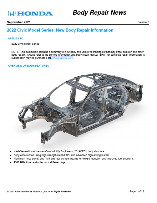
Body Repair NewsSeptember 2021 Version 2 2022 Civic Model Series: New Body Repair InformationAPPLIES TO2022 Civic Model SeriesNOTE: This publication contains a summary of new body and vehicle technologies that may affect collision and other body repairs. Always refer to the service information and body repair manual (BRM) for complete repair information. A subscription may be purchased at .OVERVIEW OF BODY FEATURES∙Next-Generation Advanced Compatibility Engineering™ (ACE™) body structure.∙Body construction using high-strength steel (HSS) and advanced high-strength steel.∙Aluminum hood panel, and front and rear bumper beams for weight reduction and improved fuel economy.∙1500 MPa inner and outer door stiffener rings.BODY CONSTRUCTION AND HIGH STRENGTH STEEL CONTENT (4-DOOR MODEL)∙Steel parts are color coded based on their tensile strength in megapascals (MPa).∙High-strength steel (HSS) is defined as any steel with a tensile strength of 340 MPa or higher.∙Ultra-high-strength steel (UHSS) is defined as any steel with a tensile strength of 980 MPa or higher.∙Steel repair and welding procedures vary depending on the tensile strength of the parts involved.NOTE: The illustrations below are for general reference only. Some body parts are constructed from multiple layers of different tensile strength steels. Always refer to the body construction section of the BRM for specific steel tensile strength information.BODY CONSTRUCTION AND HIGH STRENGTH STEEL CONTENT (5-DOOR MODEL)∙Steel parts are color coded based on their tensile strength in megapascals (MPa).∙High-strength steel (HSS) is defined as any steel with a tensile strength of 340 MPa or higher.∙Ultra-high-strength steel (UHSS) is defined as any steel with a tensile strength of 980 MPa or higher.∙Steel repair and welding procedures vary depending on the tensile strength of the parts involved.NOTE: The illustrations below are for general reference only. Some body parts are constructed from multiple layers of different tensile strength steels. Always refer to the body construction section of the BRM for specific steel tensile strength information.ALUMINUM PARTS & REPAIRABILITYThe hood of the 2022 Civic model series uses aluminum alloy construction. Minor damage to the aluminum hood may be repaired by body shops that have dedicated aluminum repair facilities and tools.RESIN COMPOSITE FRONT BULKHEADThis vehicle has a front bulkhead assembly constructed of resin composite material.∙The bulkhead design improves engine compartment access during factory assembly and service.∙The cooling fans, radiator, A/C condenser, hood lock, outside air temperature sensor, and related piping/components are attached to the front bulkhead.∙ A damaged bulkhead must be replaced.∙For more details, refer to front bulkhead replacement in the body repair manual.LASER-BRAZED ROOF PANELLaser brazed roof panels require a combination of welding, and the use of adhesives and mechanical fasteners for replacement. Refer to the roof panel replacement procedure for more details.REAR WHEEL ARCH HEM JOINTDuring the replacement of the rear side outer panel, it will be necessary to hem the entire wheel arch using modified commercially available tools, or Honda special tools. Refer to the outer panel side area replacement procedure for additional details including information on how to modify existing hemming pliers.If needed, the Honda Special Service Tool set below is available for purchase from your local Honda dealer.Tool Number Description Note07AAC-TY2A100 PLIER SET, HEMMING 3-Piece setNEW DRIVING SUPPORT SYSTEMMultipurpose Camera AimingThe 2022 Civic model series is equipped with a new driving support system that uses only the multipurpose camera and no millimeter radar unit. The multipurpose camera allows both dynamic and static aiming. Technicians now have the option to do either type of aiming depending on what their repair facility allows, or weather and traffic conditions.Refer to the following procedures for more details:∙Multipurpose Camera Aiming [Static Aiming]∙Multipurpose Camera Aiming [Dynamic Camera Aiming]Blind Spot Information (BSI) AimingThe 2022 Civic model series is also equipped with a new style blind sport information (BSI) radar units. Unlike other models, the Civic does not require the conventional BSI Radar Unit Aiming Inspection procedure. The system is now capable of self-learning while the vehicle is driven more than 19mph (31km/h). However, it is important that the BSI learning status is reset using the i-HDS whenever the following is done:∙After removing and reinstalling one or both of the BSI radar units.∙After repairing the rear panel where the BSI radar unit mounts.∙When any of the following DTCs are stored:- B18B8 Left Side BSI Radar Unit Azimuth Off Alignment- B1E68 Right Side BSI Radar Unit Azimuth Off Alignment- B18BF Left Side BSI Radar Unit Temporary Azimuth Off Alignment- B1E6F Right Side BSI Radar Unit Temporary Azimuth Off AlignmentRefer to the following for more information:∙Blind Spot Information (BSI) System Learning Value Reset∙Blind Spot Information (BSI) System DescriptionNOTE: When the status is reset, the system is limited to 9.8 ft. (3m) of detection until the self-learning is complete.Blind spot Information (BSI) Rear Bumper Repair TemplatesThe 2022 Civic model series Blind Sport Information radar units behind the rear bumper extend the detection range of previous systems but require extra consideration when repairing the rear bumper.The radar waves passing through the rear bumper are more affected by the type and location of the repair. Cracks or dents within the radar wave emission range cannot be repaired and will require bumper replacement. Scratches inside or extending into the radar wave emission range will require the whole area to be painted and polished.To assist technicians in determining where the radar wave emission area is, a printable template is provided in the body repair manual. This template can be taped onto the bumper and will help determine if the bumper can be repaired or will require replacement.4-Door template5-Door templateRefer to the following for a printable template and more details:∙Template Printed on Paper for Radar Wave Emission Range [Blind Spot Information System] ∙Precautions for Handling Bumpers [Blind Spot Information System]SUSPENSION BUSHING TIGHTENING PROCEDURETo improve ride comfort and avoid excessive twisting of the suspension bushings, the tightening of some specified suspension components must be done at close to vehicle ride height with the driver seated. Depending on the bushing being tightened, the ride height can be simulated on the ground with weight in the vehicle, or the suspension component can be adjusted to ride height position.Refer to the Tightening Procedure of Suspension Bushing for more detail.The 2022 Civic model series 4-door features an emergency trunk release separate from the trunk latch.Touring only. In addition to the trunk torsion spring, the trunk hinge is supported by a gas-filled damper to allow for one-touch opening.The 2022 Civic model series 5-door features a resin tailgate.Installing the rear window on a painted rear window opening will reduce the strength of the window adhesive in higher temperatures.If using a replacement tailgate, paint it to match the body color of the vehicle before installation. The tailgate must be masked to ensure no paint is on areas that do not have base coat applied by supplier. The following areas will need to be masked.∙The rear window opening∙The tailgate frame∙The rear view camera∙The tailgate open switch and license light area∙The holes in rear lid light areas∙The license plate holes∙The holes in the high mount stop lamp areaECU KEY WRITEA security key code protocol is being introduced for certain electronic control units (ECUs). This protocol provides secured communication between control units, helping to prevent cyberattacks from outside sources.When replacing control units like the VSA modulator control unit, you will need to access the ECU Key Write application in the i-HDS. For more information, refer to the job aid, Using the ECU Key Write Application in the i-HDS.END。
2023年款广州本田飞度发动机汽缸盖维修手册原厂资料
2023年款广州本田飞度发动机汽缸盖维修手册原厂资料2023年款广州本田飞度是一款具有出色性能和稳定性的小型汽车。
作为广州本田公司的旗舰产品之一,它一直备受消费者的青睐。
除了良好的性能和舒适的驾驶体验之外,广州本田公司也十分注重汽车的维修保养问题。
2023年款广州本田飞度发动机汽缸盖维修手册原厂资料,便是为帮助广大车主更好地维修保养自己的车辆而设计的。
一、产品介绍2023年款广州本田飞度发动机汽缸盖维修手册原厂资料是一份由广州本田公司出品的官方维修手册。
手册详细介绍了飞度汽车发动机汽缸盖的构造、属性、维修和保养等方面的知识。
它不仅包含了平时维护所需的基本信息,还包括了一些高级的知识和技巧。
无论是新手车主,还是有经验的修车专业人士,都能通过手册得到帮助和启发。
二、手册内容2023年款广州本田飞度发动机汽缸盖维修手册原厂资料共分为五个章节。
每一个章节都包含了相应方面的知识,便于车主按照自己的需求进行查阅。
第一章节为发动机汽缸盖基础知识。
手册详细介绍了汽缸盖的构造和功能,以及汽缸盖和汽车发动机其他部件之间的关系。
其中,涉及到的知识点包括汽缸盖组成、安装形式、气门的工作原理等等,对自行维修的车主来说,这些知识都是必备的。
第二章节为汽缸盖高级知识。
手册介绍了一些汽缸盖相关的高级技巧和维修安装技巧。
这些技巧可以帮助一些有经验的车主在维修和保养汽缸盖的时候更加从容和高效。
第三章节为汽缸盖故障排除和诊断。
手册介绍了汽缸盖出现故障或者失效的原因和种类。
同时,还详细介绍了如何诊断汽缸盖故障,以及如何正确地进行维修和更换。
这对于汽车维修专业人士以及有一定汽车知识的车主来说,是非常实用的参考资料。
第四章节为汽缸盖维护保养。
手册详细介绍了汽缸盖的保养和维护知识,包括汽车使用寿命、保养周期、维护方法等。
同时,手册还在这一章节提供了一些汽缸盖常见问题和解决方法的参考,让有问题的车主可以更加迅速地对汽缸盖进行维修保养。
第五章节为汽缸盖技术手册。
- 1、下载文档前请自行甄别文档内容的完整性,平台不提供额外的编辑、内容补充、找答案等附加服务。
- 2、"仅部分预览"的文档,不可在线预览部分如存在完整性等问题,可反馈申请退款(可完整预览的文档不适用该条件!)。
- 3、如文档侵犯您的权益,请联系客服反馈,我们会尽快为您处理(人工客服工作时间:9:00-18:30)。
汽车技师帮技术资料---本田飞度车身维修维修手册(车身电器维修手)
汽车技师帮技术资料---本田飞度车身维修维修手册(车身电器维修手)
汽车技师帮技术资料---本田飞度车身维修维修手册(车身电器维修手)
汽车技师帮技术资料---本田飞度车身维修维修手册(车身电器维修手)
汽车技师帮技术资料---本田飞度车身维修维修手册(车身电器维修手)
汽车技师帮技术资料---本田飞度车身维修维修手册(车身电器维修手)
汽车技师帮技术资料---本田飞度车身维修维修手册(车身电器维修(车身电器维修手)
汽车技师帮技术资料---本田飞度车身维修维修手册(车身电器维修手)