亚德客AFR,BFR系列气源处理原件(调压过滤器)
AFR半自动过滤系统说明书
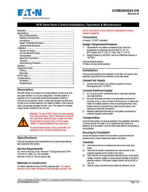
DOM0000029-ENRevision BViton ® is a trademark of DuPont™. Nordel™ is a trademark of The Dow Chemical Company. . Description ............................................................................................. 1 Specifications ......................................................................................... 1 Service Requirements ....................................................................... 1 Materials of Construction ................................................................... 1 Connections....................................................................................... 1 Design Temperature/Pressure .......................................................... 1 Airborne Noise Emissions ................................................................. 1 Installation .............................................................................................. 1 Connect Air Supply ............................................................................ 1 Connect Electrical Supply ................................................................. 1 Transportation ................................................................................... 1 Securing to Foundation ..................................................................... 1 Checklist ............................................................................................ 1 Commissioning Procedure ................................................................ 2 Operation ............................................................................................... 2 Operational Modes ................................................................................. 2 Filtering .............................................................................................. 2 Backwash .......................................................................................... 2 Control Logic .......................................................................................... 2 Troubleshooting ..................................................................................... 2 Symptoms .......................................................................................... 2 Possible Faults . (2)DescriptionThe AFR tubular unit consist of up to eight stations connect to an inlet and outlet manifold in a circular configuration. This filter system is equipped with two pneumatic double acting actuators piloted byindividual 4-way solenoid valves. A rotary type actuator provides force to index a flow diverter assembly from station to station while a second rotary type actuator actuates the drain valve. The system is controlled using a system supplied by the end user.Warning: The use of Teflon ® tape is not recommended for all pipe connections. Teflon ® tape tends to break off and clog orifices. Electrical supply voltage must match the automation enclosure rating. Incorrect supply voltage will cause damage and may cause injury. To prevent electrical shock, follow proper safe work procedures when working on electrical circuits.SpecificationsThis lists the general control specifications for a typical backwashing semi-automatic filter system.Service RequirementsAir: minimum 60 psig (4 bar), maximum 116 psig (8 bar) at 5.0 CFM (140 dm 3/m). Clean, dry, non-lubricated. Electrical: 24VDC or 120VAC (factory set).Materials of ConstructionAll wetted materials are type 316/316L stainless steel. The material selection for this vessel was based on the information provided whenthe unit was ordered. It is the customer’s responsibility to ensure material compatibility.ConnectionsAir supply: 1/2” NPTI (standard)Design Temperature/PressureTemperatures vary based on elastomer type. Maximumtemperature for elastomers: Buna N 225 °F (107 °C), EPT (Nordel) 300 °F (149 °C), Viton ® 350 °F (176 °C)Design Pressure is 250 PSIG. Maximum differential pressure is150 PSID Airborne Noise Emissions<70 dB(A) During normal operationInstallationThis document applies to the installation of the filter unit controls. See additional instructions for the installation of the filter vessel.Connect Air Supply1. Connect the air supply line (customer supplied) to the airfilter/regulator port (1/2” NPTI).Connect Electrical Supply1. All wiring and power connections need to meet local electricalcode requirements.2. No holes have been provided in the automation enclosure forincoming wiring. A hole (or holes) in the enclosure will need to be made in a suitable location to receive incoming electrical wiring. Protect internal components from metal chip and debris when making any holes and connections.3. Reference Electrical Schematic to wire system components tocustomer supplied control systemTransportationMove the filter system as close as possible to the installation site before it is removed from the crate or skid. Position the filter frame on aprepared, level foundation. Level the filter frame before it is anchored to the foundation.Securing to FoundationAnchor the enclosure stand to the foundation using the three 5/8” diameter anchor holes located at the base of the stand.Checklist☐ Verify that all service connections are secure and meet localcodes.☐ Verify that the system components are wired correctly to thecustomer supplied control system (loop check).☐ Verify that the incoming automation electrical supply is the propervoltage. Improper voltage will cause serious damage to the filter’s electrical systems. The proper voltage is factory set at 24VDC or 120 VAC☐ Verify air supply connections and proper air pressure/volumeCommissioning Procedure1.Inspect the piping connections to the filter. Verify that the inletconnection on the filter is connected to the pipe containing theincoming process fluid. Repeat this procedure for the outlet andpurge connections.2.All isolation valves to the filter should be closed. If there is abypass loop around the filter, that loop should be closed toprevent back flushing dirty process fluid into the filter.3.Open the isolation valve for the outlet piping.4.If this filter was supplied with a control package, turn on the powerto the filter system controls.5.Open the inlet isolation valve to allow approximately 25% of theflow to reach the filter.Notice: Opening the inlet valve to the fully openposition without proper ramping will cause particles tobecome wedged into the filter media. If this happens,the filter media will have to be removed and cleanedmanually.6.Over the next ½ hour, slowly introduce more of the flow until youreach 100%. You may want to manually initiate a purge duringthis time to ensure that piping debris is cleaned from the unit. OperationWarning: Mechanical and/or electrical hazards mayexist.1.The backwash sequence should be activated to keep thedifferential pressure between the inlet and outlet of the filter below15 PSID (103 kPa).2.The filter unit is supplied with a valve (or valves) used to reversethe cleaning fluid flow across the filter element. Referencedocuments named in the Control Logic section of this documentfor proper operation/sequence.3.If the filter element is removed from the unit, avoid high pressurewashing from the inside of the element. This may forcecontaminants into the filter media and cause permanent blockage and/or element damage.4.Always pressurize the unit slowly on start up and watch forleakage.5.Monitoring of the differential pressure between the inlet and outletpressures should be used to determine backwash duration andinterval. Normal operation should exhibit low differential pressure. Operational ModesFilteringThe Filter mode is the normal operating mode and follows this process description:1.Process fluid enters each unit through the inlet piping.2.The flow is distributed to the filter element.3.Debris gathers on the outside of the filter element as productflows through the screen to the outlet of the unit. BackwashingAs debris gathers on the outside of the elements, the differential pressure will begin to rise. Once the differential pressure reaches 15 PSI, it is recommended that a backwash mode be initiated backwash be initiated. This will either happen manually or automatically.The Backwash Sequence will take each Filter Vessel offline in sequence. The Index Solenoid Valve will energize to move the Diverter to the first Filter Vessel/Station allowing the inlet of the vessel to be connected to the Drain Header of the unit. Once at the first Station (as indicated by the Station Position Switch), the Drain Valve is opened, and Cleaning fluids are then diverted from the Outlet Manifold to dislodge and discharge accumulated debris collected on the outside of the Filter Element. The Filter Vessel is then placed back online, and after a short pause, the sequence continues to the remaining Filter Vessels/Stations.Control LogicReference Control Philosophy (DOQ0000149-EN), Sequence Diagram (DOQ0000150-EN) and Logic Diagram (DOQ0000158-EN). Final system performance is responsibility of the end user. Automation hardware and software (including programming) is responsibility of end user.TroubleshootingSymptomsA Actuator doesn’t operate properly (Diverter or Drain Valve)B Leakage at lid sealC Leakage where diverter shaft passes through lidD Reduction in flow rate or high differential pressureE Drop in filtrate qualityF Home Position switchG Station Position switchPossible FaultsA Actuator doesn’t operate properly1No powera Check to see if the filter system is receiving adequatepower.b Check to see if the filter system is set to the propervoltage.c Check all wiring connections.2No aira Check to see if the filter system is receiving adequateair.b Check for air leaks.c Check to see if the air bleed valve is closed and the airblock valve is open.d Check to see if the air lines are connected to thecorrect ports.3Actuator seals have been destroyeda Order a factory repair kit and replace the seals.4Faulty solenoid valvea Check to see whether the manual override button onthe solenoid valve actuates the cylinderB Leakage at lid seal1Loose lid nuts/boltsa Tighten lid/nut bolts to2Dirty lid sealing surfacesa Clean lid sealing surfaces3Damaged sealing surfacesa Repair or replace filter station4Worn lid O-ringa Remove and replace with factory lid O-ringC Leakage where diverter shaft passes through lid1Damaged or worn diverter shaft seala Inspect and replace the drive shaft seal2Packing seal too loosea.Inspect packing seal boltsD Reduction in flow rate or high differential pressure1Dirty or damaged filter screena Inspect and clean or replace filter screen2Flow, viscosity, or solids increasea Consult factoryE Drop in filtrate quality1High differential pressurea Refer to reduction in flow rate or high differentialpressure above2Damaged filter screen O-ringsa Remove and replace with factory filter screen O-rings3Damaged filter screena Remove and replace with factory filter screen4Filter screen too coarsea Consult factory for ability of filter system to accept afiner screen retention. Remove and replace withfactory filter screenF Home Position switch1Position not being founda Confirm switch is receiving proper powerb Confirm target gapc Confirm wiring in paneld Check cable connection at switch housingG Station Position switch1Position not being founda Confirm switch is receiving proper powerb Confirm target gapc Confirm wiring in paneld Check cable connection at switch housingNorth America Greater China44 Apple Street, No. 7 Lane 280Tinton Falls, NJ 07724 Linhong Road,Toll Free: 800 656-3344 Changning District, 200335 (North America only) Shanghai, P.R. ChinaTel: +1 732 212-4700 Tel: +86 21 5200-0099Europe/Africa/Middle East Asis-PacificAuf der Heide 2 100G Pasir Panjang Road53947 Nettersheim, Germany #07-08 Interlocal CentreTel: +49 2486 809-0 Singapore 118523Tel: +64 6825-1668Friedensstraße 4168804 Altlussheim, GermanyTel: +49 6205 2094-0An den Nahewiesen 2455450 Langenlonsheim, GermanyTel: +49 6704 204-0WARRANTYAll products manufactured by Seller are warranted against defects inmaterial and workmanship under normal use and service for which such products were designed for a period of eighteen (18) months after shipment from our factory or twelve (12) months after start up, whichever comes first.OUR SOLE OBLIGATION UNDER THIS WARRANTY IS TO REPAIR ORREPLACE, AT OUR OPTION, ANY PRODUCT OR ANY PARTS ORPARTS THEREOF FOUND TO BE DEFECTIVE. SELLER MAKES NOOTHER REPRESENTATION OR WARRANTY, EXPRESS OR IMPLIED,INCLUDING, BUT NOT LIMITED TO, ANY IMPLIED WARRANTY OF MERCHANTABILITY OR FITNESS FOR A PARTICULAR PURPOSE. WESHALL NOT BE LIABLE FOR CARTAGE, LABOR, CONSEQUENTIALDAMAGES OR CONTINGENT LIABILITIES. OUR MAXIMUM LIABILITY SHALL NOT IN ANY EVENT EXCEED THE CONTRACT PRICE FOR THEPRODUCT.If you are interested in ordering spare parts or having service performed on your filter, please contact Customer Service.Eaton reserves the right to change specifications, dimensions and model designations without prior notice. For more information, pleaseemail us at ********************or visit /filtration© 2021 Eaton. All rights reserved. All trademarks and registered trademarks are the property of their respective owners. All information and recommendations appearing in this brochure concerning the use of products described herein are based on tests believed to be reliable. However, it is the user’s responsibility to determine the suitability for his own use of such products. Since the actual use by others is beyond our control, no guarantee, expressed or implied, is made by Eaton as to the effects of such use or the results to be obtained. Eaton assumes no liability arising out of the use by others of such products. Nor is the information herein to be construed as absolutely complete, since additional information may be necessary or desirable when particular or exceptional conditions or circumstances exist or because of applicable laws or government regulations。
AFF

注)带托架的隔板不可安装。 请使用附属的托架。
可选项追加 ( ) AMG□C,AFF□C,AM□C,AMD□C AMH□C,AME□C,AMF□C
5 追加: 种
压差开关
1.6MPa规格
氟橡胶规格
带压差开关(AC125V, DC30V) 带压差开关(DC30V) 脱脂洗净、白色凡士林规格
AMH+AME+AMF ※仅C型可模块式连接。
AMF350C 3/8, 1/2 132 18 98 90 5 90 10 150 80 28 8 7 7 14 7 12 50 95 34 80 5 2.3
57
外形尺寸图 AMF450C, AMF550C
P D Q
除臭过滤器 AMF 系列
M T
A B
E R
D N
U
L
托架 (附属品)
øW
K
V
J
进
出
7 O形圈
NBR
JIS B2401G35 JIS B2401G35 JIS B2401G35 JIS B2401G35 JIS B2401G35
1个
1个
3个Βιβλιοθήκη 3个5个56
AMF 系列
外形尺寸图 AMF150C~AMF350C
P Q
T
S
R
F
E
D
N
U
L
托架
(附属品)
O
M
øW
K
V
J
IN
OUT
A B
I C
维护空间 G
(mm)
型号
接管口径 A B C D E F G
托架相关尺寸
I N J K U V L MWO P Q R S T
AF200系列自动滤水器使用说明书
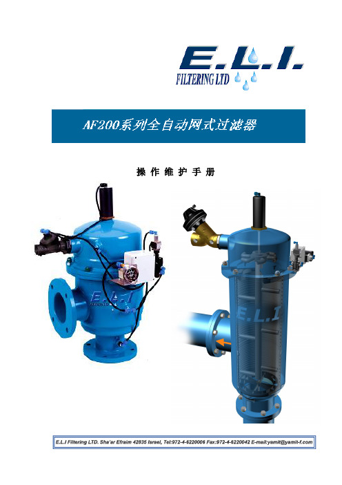
维修保养手册操作维护手册目录简介------------------------------------------------------------------------------------------------------------- 2 AF200系列过滤器------------------------------------------------------------------------------------------- 3 技术参数---------------------------------------------------------------------------------------------------- 4 压损表------------------------------------------------------------------------------------------------------- 5 工作原理---------------------------------------------------------------------------------------------------- 6 安装注意事项---------------------------------------------------------------------------------------------- 8 调试步骤---------------------------------------------------------------------------------------------------- 9 点检基准---------------------------------------------------------------------------------------------------- 13 部件描述---------------------------------------------------------------------------------------------------- 15 电磁阀---------------------------------------------------------------------------------------------------- 15 压差指示仪---------------------------------------------------------------------------------------------- 19 排污阀---------------------------------------------------------------------------------------------------- 22 液压活塞------------------------------------------------------------------------------------------------- 24 滤网------------------------------------------------------------------------------------------------------- 26 控制器描述------------------------------------------------------------------------------------------------- 30 直流控制器---------------------------------------------------------------------------------------------- 30 交流控制器---------------------------------------------------------------------------------------------- 31 故障解决办法---------------------------------------------------------------------------------------------- 39 零件图------------------------------------------------------------------------------------------------------- 41 直流控制器控制管线接线图---------------------------------------------------------------------------- 45 交流控制器控制管线接线图---------------------------------------------------------------------------- 46 全球质量保证书---------------------------------------------------------------------------------------------- 47E.L.IE.L.I伊尔艾过滤设备有限公司,总部位于以色列,是一家专门生产过滤设备,并针对用户特殊需要提供过滤解决方案的设计/生产厂家。
SMC F.R.L三联件 ACG

出口压力 MPa
0.15
0 0 0.2 0.3 0.4 0.5 0.6 0.7 0.8 0.9 1.0
入口压力MPa
0.15
0 0 0.2 0.3 0.4 0.5 0.6 0.7 0.8 0.9 1.0
入口压力 MPa
0.15
0 0 0.2 0.3 0.4 0.5 0.6 0.7 0.8 0.9 1.0
浮子式自动排水器(N.O.)
0.02~0.2MPa设定
金属杯体
油雾器上带排油活门
尼龙杯体
带液位计的金属杯体
带保护罩
带排水导管
非溢流型
流动方向 :右→左
排水活门上带倒钩接头
减压阀手轮朝上
标牌、杯体注意表示、 压力表的单位为PSI、°F
:可组合 。 :不可组合 。 :与型号有关。 :仅螺纹种类为NPT的场合。
ACG20□~40□
3 油雾器上带排油活门
ACG20□~40□
6 杯体,滴下窗材质:尼龙
ACG20□~40□
8 带液位计的金属杯体
ACG30□、40□
C 注9)J
N
带保护罩 过滤器杯体上带排水导管 非溢流型
ACG20□ ACG20□~40□ ACG20□~40□
R 流动方向:右→左
ACG20□~40□
注4) 残压释放3通阀
ACG20用 GB2-10AS GB2-3AS
AD27 —
Y200 Y200T AKM2000-□01、(□02) IS1000M-20 VHS20-□01、□02
附件/可选项型号 ACG30用 GB3-10AS GB3-3AS AD37 AD38 Y300 Y300T
AKM3000-(□01)、□02 IS1000M-30
实训报告6 MPS送料站的安装、接线和调试
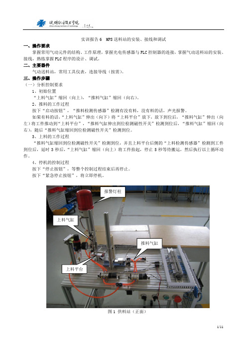
实训报告6 MPS 送料站的安装、接线和调试一、操作要求掌握常用气动元件的结构、工作原理,掌握光电传感器与PLC 控制器的连接,掌握气动送料站的安装、接线,熟练掌握PLC 程序的设计、调试。
二、主要器件气动送料站,常用工具仪表,连接导线(按需)。
三、操作步骤(一)分析控制要求1、初始位置“上料气缸”缩回(向上),“推料气缸”缩回(向右)。
2、推料的工作过程按下“启动按钮”,“推料检测传感器”检测有没有料,没有料的话,声光报警。
如果有料的话,“上料气缸”伸出(向下)将“上料平台”放下,放下到位后,“推料气缸”伸出(向左)将工件推动到“上料平台”,“推料气缸伸出到位检测磁性开关”检测到位后,“推料气缸”缩回(向右),随后“推料气缸缩回到位检测磁性开关”检测到位。
3、上料的工作过程“推料气缸缩回到位检测磁性开关”检测到位,并且上料平台后侧的“上料检测传感器”检测到工件到位后,延时3秒后,“上料气缸”缩回(向上)将工件抬起,停止5秒等待搬运,然后执行以上循环动作。
4、停机的控制过程按下“停止按钮”,等整个控制过程结束后再停止。
按下“紧急停止按钮”,将立即停机。
图1 供料站(正面)上料气缸上料平台推料气缸报警灯柱推料检测传感器上料检测传感器图2 供料站(背面)气动二联件接线端子气动换向阀按钮电源、控制器图3 供料站(侧面)(二)熟悉气动、电气元件1、气动元件:二联件、气缸、换向阀、节流阀、气管、磁性开关等。
访问,亚德客/了解相关产品信息,并下载产品目录。
参考亚德客产品型录2012_3D、亚德客产品型录2011_PDF,进行相关器件的选型。
(1)气源处理元件的选型。
气源处理元件重点查阅以下元件:调压过滤器GFR系列\FRL\GC\Airtac2011-GFR.pdf (2)控制元件的选型。
控制元件重点查阅以下元件:4V100系列\Valves\3V 4V\ Airtac2011-4V100.pdf(3)执行元件的选型。
气源处理元件

4)杯罩安装部有漏气
原
因
O形圈未装好
O形圈有损伤
杯罩破损
対
策
装好O形圈
更换
更换杯罩
第三十九页,课件共有40页
AL产品选型说明
第四十页,课件共有40页
空气组合元件
记号
-A B C D
空气过滤器 (AF) ① – ① ① –
减压阀 (AR)
② – ② ③ –
螺纹种类
无记号为RC(PT)螺纹 元件的构成
油雾器 (AL)
过滤减压阀 (AW)
③
–
②
①
–
–
–
–
–
①
油雾分离器 (AFM)
– – – ② ②
连接口径
M5 M5×0. 8
01
1/8
02
¼
03
3/8
保护罩能快速装卸加压时有防止回转结构将螺钉拧紧便组装完成监视盘气动三联组合气动三联组合frl气动三联组合气动三联组合frlfrl过滤器过滤器afaf气动三联组合气动三联组合frlfrl减压阀减压阀arar104080120lbfinbarp1p2反馈孔膜片调压弹簧溢流孔气动三联组合气动三联组合frl油雾器alalac系列空气组合元件模块型型号表示方法10m5201825303840记号元件的构成空气过滤器af减压阀aral过滤减压阀aw油雾分离器afm组合件大小空气组合元件空气组合元件螺纹种类无记号为rcpt螺纹m5m50
04
½
06
¾
10
1
记号 C D
G/E
名称 自动排水器 自动排水器
压力表
附属品
适用机种
浮子式(N.C.):AC10~AC60 浮子式(N.O.):AC2500~AC6000
亚德客产品介绍—设计人员(09版)

活塞上增加了耐磨 环结构,使其导向 精度和支撑能力大 为提高
气缸本体作硬质氧化、滚压处理 运动阻力小,缸体更耐磨
采用进口润滑脂,降低了 低温低速时的爬行现象 及“星期一效应”
一旦加油润滑,中途不可 停止
2008 - 7
26
迷你气缸系列
27
MI不锈钢笔型气缸:
◆执行ISO6432标准 ◆有固定式缓冲与可调式气缓冲 ◆前后盖采用铆合连接 ◆不锈钢缸筒 ◆缸径规格:8、10、12、16、
多位置 ◆固定方式: FA、FB、LB、CB 等同于:SMC的CQ2系列治具气缸 N0RGREN:RM/9200
2008 - 7
24
ACP系列薄型气缸:
◆执行DIN标准 ◆带前后固定橡胶缓冲 ◆带耐磨导向环 ◆活塞采用铆合式;前、后盖与本体
为螺栓连接 ◆缸径规格:12、16、20、15、32、
40、50、63、80、100 ◆作动方式:单动、复动
2008 - 7
21
薄型气缸系列
22
SDA薄型(治具)气缸:
◆执行亚德客企业标准 ◆带前后固定橡胶缓冲 ◆带耐磨导向环 ◆活塞及后盖的连接采用铆合式 ◆缸径规格:12、16、20、15、
32、40、50、63、80、100 ◆作动形式:单动、复动 ◆活塞杆牙:内牙、外压、无牙 ◆主要形式:双轴、双轴(可
等同于:
我司型号(AIRTAC) SG SGC
NORGEN(英国) /
RA/8000
SMC(日本) CS1系列(不符合ISO) CS1系列(不符合ISO)
FESTO(德国) DNG系列 /
2008 - 7
18
带锁气缸:
◆执行亚德客企业标准 ◆SC系列为拉杆型 ◆SU系列为米字型 ◆前后端盖可分别带锁,广泛用 于除尘设备行业 ◆缸径规格:32、40、50、63、 80、100
R&D技术培训记录 2
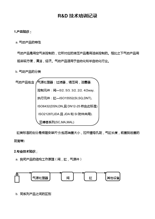
R&D 技术培训记录1.产品知识;a. 气动产品的特性气动产品是用空气来控制的,它所对应的液压产品是用油来控制的。
相比之下气动产品用起来较方便,清洁,经济。
气动产品适用于自动化和半自动化行业。
b. 气动产品的分类气动产品包含:气源处理器:过滤器,调压阀,油雾器.控制元件:阀—5/2. 5/3. 3/2. 2/2. 4/2way.执行元件:缸—ISO15552(SI,SQ,DNT),ISO6432(DSN,DN,且DN12-25符合此标准)ISO21287(JDA且JDA和SI附件共用).亚德客系列(SC,MA,MAL)缸类标准的划分是根据安装尺寸(包括端盖大小,拉杆螺母孔距,气缸长度,前盖到后盖的距离等)2.专业技术知识;a. 我司产品的结构工作原理(阀,缸,气源件)气源处理器阀缸其他设备b. 同系列产品之间的区别1) 双电控电磁阀有记忆功能。
2) 单电控电磁阀有自动复位功能(3/2way电磁阀和气控阀主要用于控制单作用缸,分为NC和NO。
5/2way 和4/2way效果一样。
4/2way阀是R口和S口并在一起。
2/2way一般齐开关作用。
)3) 阀分为:直动式:3V1-06. 2P025. 2W025(其中3V1进气孔标准为1mm).先导式:4V.3V(线圈斜着的2/2way 都是先导式.此符合表示先导式.注:交流线圈可以由直流线圈替代,反之不可。
先导式分为:内部先导和外部先导.外部先导适用于当内部先导低于0.15Mpa,无法驱动电磁阀运转时,可通过外部先导.直动阀流量偏小,功率高。
而先导式流量大,功率小.4)两个2/2way 可以构成一个3/2way. 两个3/2way可以构成一个5/2way.3. 我们新开发的不锈钢活塞杆和普通的碳钢活塞杆(镀铬)有什么区别?气缓冲和垫缓冲的区别和联系各有什么优点?a.不锈钢活塞杆较碳钢活塞杆耐腐蚀,适用于恶劣环境中。
碳钢活塞杆表面都镀一层铬(此为标配)且活塞杆螺纹处都带有油和防护套,防止生锈。
自动化非标设计各标准件选型知识概要86

【推荐】自动化非标设计各标准件选 型知识 概要86
预压力:
所谓预压力是预先给予钢珠负荷力,利用钢珠与珠道之间负向间隙给予预压,这样能够提 高直线导轨的刚性和消除间隙。
按照预压力的大小可以分为不同的预压等级。如台湾上银公司(HIWIN)提供六种标准预 压,预压力从有间隙到0.13C不等。 C值为动额定负荷。
调压阀:调节压力高低;消除上流 压力的波动影响,保证输出压力 稳定;
给油器:无需润滑的元件可以不给 油,但是一旦给油后就不得中途停 止供油,同时,要防止冷凝水进 入元件内,以免冲洗掉润滑油。
过滤器
调压阀
给油器
电磁控制阀选型标准
➢I接头和Y接头 ➢鱼眼接头 ➢浮动接头
气缸配件接头选择
普通的机构连接用, 不能承受偏心负载
密封件材质
特点
TPU
耐磨性能更好,可用于重负载型气缸摆动安装时,气缸使用寿 命更长,有一定的刮尘作用(粉尘较多或有金属颗粒不能使用, 请联系我们),还可耐移印机行业的油墨
NBR 普通气缸,用于一般性工作环境
氟橡胶 耐高温性气缸,该类型的气缸可在200度的环境中正常使用
过滤器:除去压缩空气中的固态杂 质、水滴和污油滴等。不能除去 气态的水、油;
安装非常方便,使用寿命长,在很多机械 上使用,是最常见的缓冲器; 3) 橡胶缓冲器 这种缓冲器价格低,抗压力能 力弱,使用寿命短; 4) 弹性缓冲器 对环境无要求,恶劣环境下可 使用,反应力度大,所占空间大,适用于2 米每秒的起重机中; 5) 液气缓冲器 性能最佳,是液压缓冲器的改 良品种; 6) 弹性胶泥缓冲器 性能优良,结构设计简单, 质量可靠,完全依靠弹性胶泥的缓冲力, 常年无需防护;
AFR BFR系列调压过滤器 说明书
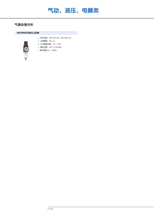
气源处理元件AFR/BFR 系列调压过滤器符合标准JB/T7374-94、JB/T7376-94过滤精度:40μm 工作温度范围:5℃~60℃调压范围:0.05~0.95 MPa 最大耐压力:1.5MPa:H气源处理元件 气动辅件AF/BF 系列过滤器符合标准JB/T7374-94过滤精度:40μm 工作温度范围:5℃~60℃最大耐压力:1.5MPa: AR/BR 系列调压阀符合标准JB/T7376-94工作温度范围:5℃~60℃调压范围:0.05~0.95 MPa 最大耐压力:1.5MPa:AL/BL 系列油雾器符合标准JB/T7375-94工作温度范围:5℃~60℃最大耐压力:1.5MPa:SFC 系列二联件符合标准JB/T7374-94、JB/T7375-94、 JB/T7376-94过滤精度:40μm 工作温度范围:5℃~60℃调压范围:0.05~0.95 MPa 最大耐压力:1.5MPa:NU 系列三联件符合标准JB/T7374-94、JB/T7375-94、 JB/T7376-94过滤精度:5μm工作温度范围:0℃~60℃最大耐压力:手动排水型:1.6MPa ,自动排水型:1.2MPa:NFR 系列过滤带调压阀符合标准JB/T7374-94、JB/T7375-94、 JB/T7376-94过滤精度:5μm工作温度范围:0℃~60℃最大耐压力:手动排水型:1.6MPa ,自动排水型:1.2MPa: NF 系列过滤器符合标准JB/T7374-94过滤精度:5μm工作温度范围:0℃~60℃最大耐压力:1.6MPa:NR系列调压阀符合标准JB/T7376-94工作温度范围:0℃~60℃最大耐压力: 1.6MPa:NL 系列油雾器符合标准JB/T7375-94工作温度范围:0℃~60℃最大耐压力:1.6MPa:PU 系列气管符合标准JB/T2351-93工作温度范围:-5℃~60℃使用压力范围:0~1.0 MPa:。
搅拌站生产线设备清单

主机1编号:780230 主机1编号:780230
减速机(平皮带) BWD5-17-15 电机(平皮带) Y160M-4 15KW,1460r/min,380V,30.3A 减速机(斜皮带) BWD5-17-22 电机(斜皮带) Z-180L-4 22Kw,1470r/min,380V
亚德客 亚德客 亚德客 亚德客 亚德客 亚德客 亚德客 亚德客 亚德客 亚德客 亚德客 亚德客
4 2 2 2 2 4 2 12 8 8 6 2 6 1台 1台 1台 1套 3套 1套 1套 1台 1台 1台 1台 1台 1台
砂石气缸使用 地仓
水称 二元件 生产线用 粉仓顶除尘
收尘系统
电焊机400 电焊机200 维修设备 切割机 氧割 HP672 组装机 生产电脑 联想家悦 打印机 OKI 打印机 OKI 120吨地磅 地磅 计量仪
惠普 联想 OKI OKI 南宁衡器厂 上海耀花
16米磅体+20T传感器X8个
发电机 135柴油机135系列 250KW 交流发电机 TFW系列
无刷同步交流
安装日期 启用日期
2010年10月 2010年10月 2003年10月 2003年11月 2003年10月 2003年11月
2003年10月 2003年11月 2003年10月 2003年11月 2003年10月 2003年11月 2003年10月 2003年11月 2003年11月 2003年11月 2007年10月 2007年11月 2007年10月 2007年11月 2007年10月 2007年11月 2007年10月 2007年11月 2007年10月 2007年11月 2007年10月 2007年11月 2007年10月 2007年11月 2007年10月 2007年11月 2007年10月 2007年11月 2007年10月 2007年11月 2007年10月 2007年11月 2007年10月 2007年11月 2007年10月 2007年11月 2007年10月 2007年11月 2007年10月 2007年11月 2007年10月 2007年11月 2007年10月 2007年11月 2007年10月 2007年11月 2007年10月 2007年11月 2003年10月 2003年11月 2003年10月 2003年12月 2003年11月 2003年12月 2003年11月 2003年12月 2003年11月 2003年12月 2003年11月 2003年12月 2003年11月 2003年12月 2003年11月 2003年12月 2003年11月 2003年12月 2003年11月 2003年12月 2003年11月 2003年12月 2003年11月 2003年12月 2003年11月 2003年12月 2003年11月 2003年12月 2003年11月 2003年12月
