EMC Standards and Their Application
emc辐射值标准
emc辐射值标准EMC辐射值标准是衡量电磁辐射水平的一种指标,用于评估电子设备对人体健康的潜在影响。
本文将介绍EMC辐射值标准的背景、应用范围、测量方法以及相关的安全性评估。
一、背景电子设备的广泛应用给人们的生活带来了很大的便利,但同时也引发了对电磁辐射对人体健康的担忧。
为了保护公众的健康,各国纷纷制定了相关的电磁辐射标准,其中EMC辐射值标准是最常用的一种。
二、应用范围EMC辐射值标准适用于各种电子设备,包括通信设备、无线电设备、电视机、计算机等。
这些设备在正常工作时会产生电磁辐射,因此需要通过测量其辐射值来评估其对人体健康的潜在影响。
三、测量方法测量EMC辐射值需要使用专业的测试仪器,如电磁辐射测试仪。
测试时,将待测设备放置在测试仓内,然后通过测试仪器测量辐射场强度。
根据不同国家的标准要求,测量可以在不同频段和距离下进行。
四、安全性评估根据EMC辐射值标准,可以对电子设备的辐射水平进行安全性评估。
一般来说,电子设备的辐射值应低于规定的限值,以确保对人体健康的潜在影响在可接受范围内。
如果辐射值超过限值,需要采取相应的措施进行辐射防护或改进设备设计。
五、结论EMC辐射值标准是衡量电子设备辐射水平的重要指标,对保护公众健康具有重要意义。
通过测量辐射值并进行安全性评估,可以确保电子设备在正常使用时不对人体健康造成潜在伤害。
因此,制定和遵守EMC辐射值标准对于电子设备的生产和使用具有重要意义。
六、参考文献[1] EMC Measurement Guidance Note, National Measurement Office, UK[2] Electromagnetic Compatibility and Radio Spectrum Matters (ERM), European Telecommunications Standards Institute。
IEC标准中的EMC测试要求介绍
05/01/99
Standards 6
3
R
The European Single Market
• This changed with the introduction of the single market in Europe • Individual member countries’ legislation was seen as a potential barrier to trade • The EEC directive on EMC was intended to give one standard for all of Europe
05/01/99 Standards 6 8
R
United States
FCC Part 15
– Legal requirement for all ITE equipment – Emissions only – Tests can only be performed in FCC approved laboratories
• Standards are produced by Standards Australia.
• C-Tick Mark is used to denote compliance with EMC standards
05/01/99 Standards 6 16
R
Not Only Legislation
05/01/99
Standards 6
9
R
Japan
• Voluntary standards under the VCCI scheme have existed in Japan since late 1985. • VCCI covers data processing and office automation equipment. • Although voluntary, VCCI is very strongly supported in Japan. • General movement towards adopting IEC standards.
EMC检验的送检要求及说明
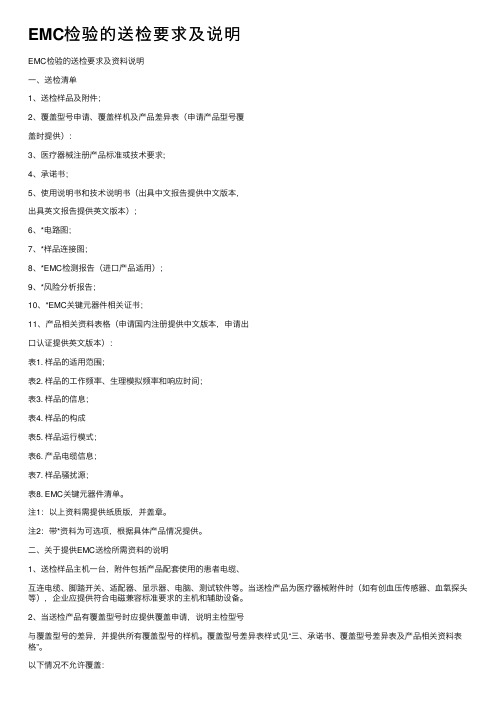
EMC检验的送检要求及说明EMC检验的送检要求及资料说明⼀、送检清单1、送检样品及附件;2、覆盖型号申请、覆盖样机及产品差异表(申请产品型号覆盖时提供):3、医疗器械注册产品标准或技术要求;4、承诺书;5、使⽤说明书和技术说明书(出具中⽂报告提供中⽂版本,出具英⽂报告提供英⽂版本);6、*电路图;7、*样品连接图;8、*EMC检测报告(进⼝产品适⽤);9、*风险分析报告;10、*EMC关键元器件相关证书;11、产品相关资料表格(申请国内注册提供中⽂版本,申请出⼝认证提供英⽂版本):表1. 样品的适⽤范围;表2. 样品的⼯作频率、⽣理模拟频率和响应时间;表3. 样品的信息;表4. 样品的构成表5. 样品运⾏模式;表6. 产品电缆信息;表7. 样品骚扰源;表8. EMC关键元器件清单。
注1:以上资料需提供纸质版,并盖章。
注2:带*资料为可选项,根据具体产品情况提供。
⼆、关于提供EMC送检所需资料的说明1、送检样品主机⼀台,附件包括产品配套使⽤的患者电缆、互连电缆、脚踏开关、适配器、显⽰器、电脑、测试软件等。
当送检产品为医疗器械附件时(如有创⾎压传感器、⾎氧探头等),企业应提供符合电磁兼容标准要求的主机和辅助设备。
2、当送检产品有覆盖型号时应提供覆盖申请,说明主检型号与覆盖型号的差异,并提供所有覆盖型号的样机。
覆盖型号差异表样式见“三、承诺书、覆盖型号差异表及产品相关资料表格”。
以下情况不允许覆盖:a.按产品种类划分,种类不同的产品不能互相覆盖;b.按产品⼯作原理划分,⼯作原理不同的产品不能互相覆盖;c.按影响产品电磁兼容性的关键件划分,关键件、印刷电路图、电⽓结构不同的产品不能互相覆盖;d.同⼀商标、同⼀规格型号的产品,由不同产地⽣产的不能互相覆盖;e.台式设备与落地式设备之间不能互相覆盖。
3、申请中⽂报告检验时,医疗器械注册产品标准中应包含电磁兼容性的条款信息,英⽂报告不需要提供。
根据国家规定不再要求企业提供注册产品标准时,企业只需提供技术要求,技术要求中应包含电磁兼容性的信息。
emc调节方法

emc调节方法English:EMC (electromagnetic compatibility) is the ability of electronic equipment to operate properly in the presence of electromagnetic interference, and to not emit electromagnetic interference that could interfere with other equipment. There are several methods to regulate EMC, including proper design and shielding of electronic devices to prevent interference, testing and certification of electronic equipment to ensure compliance with EMC standards, and using filters and suppression components to reduce electromagnetic interference. Additionally, proper grounding and routing of signal and power cables can help minimize electromagnetic interference. It is important for manufacturers of electronic equipment to adhere to EMC regulations to ensure their products do not cause or suffer from electromagnetic interference, and to protect the overall integrity and functionality of electronic systems.中文翻译:EMC(电磁兼容性)是电子设备在电磁干扰的情况下正常运行的能力,以及不发出可能干扰其他设备的电磁干扰。
EMC Standards (1)
US/CA EMC standards introduction
USA FCC (Unintentional) Part 15 Subpart B (Digital Device) FCC (Intentional) Part 15 Subpart C 15.227 (26.96MHz27.28MHz) 15.231 (間接性發射) 15.247 (展頻) 15.249 (非展頻-2.4GHz) Part 15 Subpart E ICES-003 (Digital Device) Canada IC (Unintentional) IC (Intentional) RSS-210 6.2.2 (o) (展 頻) RSS-210 6.1 (間接性 發射) RSS-210 6.2.2 (m2) (非展頻-2.4GHz)
Page 11
Antenna Requirement 天線要求 Restricted Bands of Operation 限制頻段 Conducted Limits 故意輻射 – 傳導干擾 Radiated Limits 故意輻射 – 輻射干擾 操作頻率 : 26.96 – 27.28MHz Ex. Wireless Keyboard, Wireless Mouse…. 操作頻率 : 40.66 – 40.70MHz and above 70MHz Ex. 15.231 Remote Controller 15.247 操作頻率 : 902 – 928MHz, 2400 – 2483.5MHz and 572557255875MHz Ex. Wireless LAN, Bluetooth… 操作頻率 : 902 – 928MHz, 2400 – 2483.5MHz and 5725572515.249 5875MHz Ex. Video Sender…
上衣各部位名称和常用的量度文法
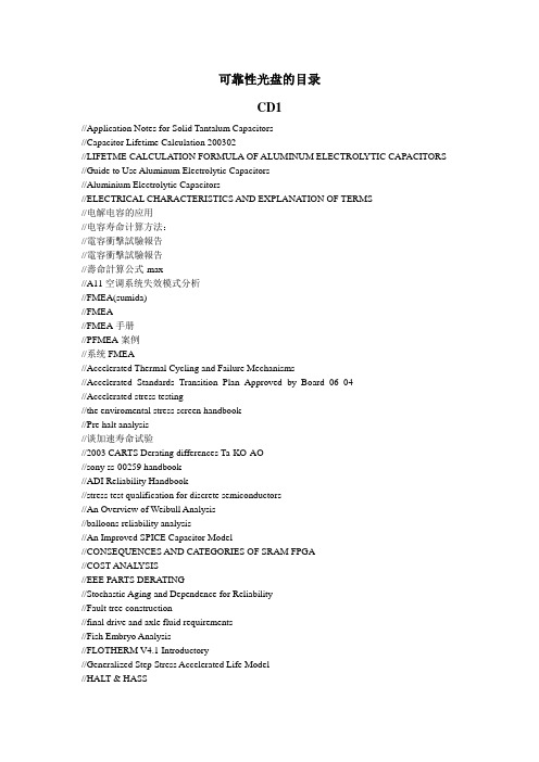
可靠性光盘的目录CD1//Application Notes for Solid Tantalum Capacitors//Capacitor Lifetime Calculation 200302//LIFETME CALCULA TION FORMULA OF ALUMINUM ELECTROLYTIC CAPACITORS //Guide to Use Aluminum Electrolytic Capacitors//Aluminium Electrolytic Capacitors//ELECTRICAL CHARACTERISTICS AND EXPLANA TION OF TERMS//电解电容的应用//电容寿命计算方法://電容衝擊試驗報告//電容衝擊試驗報告//壽命計算公式-max//A11空调系统失效模式分析//FMEA(sumida)//FMEA//FMEA手册//PFMEA案例//系统FMEA//Accelerated Thermal Cycling and Failure Mechanisms//Accelerated_Standards_Transition_Plan_Approved_by_Board_06_04//Accelerated stress testing//the enviromental stress screen handbook//Pre halt analysis//谈加速寿命试验//2003 CARTS Derating differences Ta-KO-AO//sony ss-00259 handbook//ADI Reliability Handbook//stress test qualification for discrete semiconductors//An Overview of Weibull Analysis//balloons reliability analysis//An Improved SPICE Capacitor Model//CONSEQUENCES AND CA TEGORIES OF SRAM FPGA//COST ANALYSIS//EEE PARTS DERA TING//Stochastic Aging and Dependence for Reliability//Fault tree construction//final drive and axle fluid requirements//Fish Embryo Analysis//FLOTHERM V4.1 Introductory//Generalized Step Stress Accelerated Life Model//HALT & HASS//IBM ASIC Products Application Note//IEC 60950//Improving the Performance of Y our Root Cause Analysis (RCA) Program//The Application of Accelerated Testing Methods and Theory Accelerated Testing Methods and Theory HALT-HASS//Life Testing and Reliability Predictions for Electromechanical Relays//MAXIM reliability report//TESTING FOR RELIABILITY IN SPACE SYSTEMS//MTBF Instruction Guide//MTBF 計算方法概論//MODELING AND SIMULA TION OF RELIABILITY& MAINTAINABILITY PARAMETERS FOR REUSABLE LAUNCH VEHICLES USING DESIGN OF EXPERIMENTS //on precendence life testing//MEASUREMENT PRACTICES FOR RELIABILITY AND POWER QUALITY//POST PROGRAMMING BURN IN (PPBI) FOR RT54SX-S AND A54SX-A ACTEL FPGAS //Profile_PAL_draft_v1_3b//MINI DIN Series ConnectorProduct Specification(For Internal Use)// USB Series ConnectorProduct Specification(For Internal Use)//THE RETAIL ELECTRIC COMPETITION TASK FORCE//Reliability as a Systems Engineering Investment Not Just a Cost//Reliability Design Technology for Power Semiconductor Modules//Reliability Programs//Reliability Engineering Principles//Reliability Testing and Data Analysis of High-Density Packages’Le ad-Free Solder Joints//Dynamic reliability and risk assessment of the accident localization system of the Ignalina NPP RBMK-1500 reactor//Semiconductor Device Reliability Failure Models//Software Reliability Handbook Chaper11//SONY SS-00259-1第四版(英日)//SONY00254-5-R4//Standard Linear IC reliability//Stress test Qualification for Integrated Circuits//System A vailability Modelling//The Challenge of Supporting Aging Naval Weapon Systems Aging Naval Weapon Systems//Using Telcordia Calculation Methods to Adjust Failure Rates//Warranty Cost An Introduction//wetting balance theory//包装试验方法//产品的热设计方法无图//电子产品可靠性设计及预计//环境应力筛选(ESS)//基于模糊优化的零部件疲劳寿命可靠性分析//结构可靠性分析的区间方法//可靠性基本计算//可靠性预计方法及一点思考//可信性工程//零库存系统//潜在失效模式和效果分析//潜在失效模式和效果分析2//浅析2×xkW汽车电站双机组对可靠性的影响//塑膠產品外觀印刷品質檢驗標準//维护和可靠性//系统可靠性理论与工程实践//以可靠性为中心的维护保养//主板可靠性测试标准流程//半导体集成电路的可靠性设计//产品全寿命周期管理中的加速环境试验技术//当代质量观与可靠性//电子元器件的可靠性安装//电子元器件的运输、储存和测量//电子元器件的质量与可靠性军用标准体系//电子专用设备的可靠性试验//电阻器与电位器的可靠性//二十世纪留给二十一世纪可靠性工程热点问题//防止可靠性设计分析中的若干片面性//非工作期微电路的可靠性及其预计//高加速寿命试验(HALT)与高加速应力筛选(HASS)//功率模块可靠性//国外可靠性工程发展//国外直升机可靠性维修性和保障性发展综述//合理选择继电器提高家电可靠性//基于环境的大型结构物模态试验//几种电子元器件长期储存的失效模式和失效机理//可靠度保證-工程與管理技術之應用//可靠性工作主要内容//可靠性管理//可靠性试验的编码故障树分析//可靠性预计和分配的作用原理及预期效益//可靠性预计模型的参数敏感度分析//可靠性增长试验的体会//美国可靠性分析中心(RAC)的可靠性培训课程//美国可靠性强化试验技术发展点评//某平显可靠性鉴定试验及思考//失效率//失效率曲线的分析与新修正模型的建立//寿命数据分析理论参考英文版//台式电脑电子系统的驱动器可靠性评估//微电路的质量、可靠性等级//微电路降额设计指南//未来电子系统封装可靠性面临的困难//一种威布尔寿命分布模型//一种威布尔寿命分布模型//元件可靠性EMC//EMC电磁屏蔽材料设计者指南//EMC文章集合(共50篇)//如何尽量降低PCB板上的地噪声//防雷器在电源系统中的应用// 运算放大器的选择方法//新一代数字IC//电子设备、分系统和系统的电磁兼容设计中的可靠性考虑//射频屏蔽室屏蔽效能的测试技术//磁屏蔽理论和实践//局域网的电磁能量泄漏//开关电源EMI滤波器的正确选择与使用//如何选择屏蔽外壳//ESD//Electronic Design//Electronic System Design//EMC design technology//High-Speed Board Design Techniques//集肤效应//Bus LVDS SER/DES FAQs//ACPI Component Architecture Programmer Reference//A critique of the EMC Directive//Abatement of Static Electricity//An EMC Directive for the Next Century//COMPLIANCE SYSTEMS CORPORA TION app_note_EN61000-4-5 //Australian EMC Regulation and Routes to Compliance//Building a Bridge Between Product Safety and EMC//Commercial Practices Standard Set to Replace MIL-STD 1686//Developments in Electrical Safety Testing//Electrical Safety Testing//Electromagnetic Compatibility//EMC & EMI of computer//What to look for in an emc amplifiers//EMC annata select//What to look for in an emc antennas//EMC base 基本概念//EMC Chamber Calibration//EMC Problems with Mobile Radio//EMC Shielding//信息技术设备的电磁兼容性标准//EMC Standards and Their Application//EMC standards of all//EMC Standards//EMC test and design The Impact of Emerging European Standards 、//Trends in EMC Testing of household appliance//智能型框架式断路器单片机系统的电磁兼容性分析//滤波器在抗EMI中的应用及发展//Selecting the Right Fabric-Over-Foam EMI Gasket//EMI Requirements in Japan//Electromagnetic Interference (EMI) Damage to Giant Magnetoresistive (GMR) Recording Heads //Evaluating the Nonmagnetic Shields//Explosion Protection—The New Approach in Europe//地线干扰与抑制//超大规模集成电路中的可靠性技术应用与发展//Medical EMC Standards//Minimizing EMI from Heat Sinks//Mitigating EMI in High-Speed Digital Transmission Networks//Performing Safety Tests to Comply with the Low V oltage Directive//Product Safety Standards//Product Safety: Requirements and Methods//Terminology for electromagnetic compatibility//The FCC in Action to Address New EMC ConcernsBA TTERY//Advanced Battery Engineering Facility//An Analysis and Performance Evaluation of a Passive Filter Design Technique for Charge Pump PLL’s AN-1001//Introduction to Power Supplies//Don''t Throw A way Those Batteries!//battery charging//Keep Batteriies Alliive Through Better Battery Chargiing//Demonstrates ACT battery chargers with enrev technology because ―Help Can’t Wait‖//Cycling Information//Efficiency and Power Utilization Data Guide DC DC Conversion Choices in Battery Operated Devices//DC/DC变换器中的噪声管理//DESIGN & SAFETY CONSIDERA TIONS//down the idle power DS92LV16 Design Guide//National Semiconductor DS92LV16 Design Guide//A USER GUIDE TO COMPENSA TING LOW-DROPOUT REGULA TORS//SWITCHING REGULA TORS//Buck-converter Charger also Provides System Power//Frequently Asked Questions About Regulators//Batteries The Achilles Heel in Wireless Communications//Radio Reliability Depends on Careful Planning and Better Battery Charging//锂离子电池知识汇萃//如何选择锂离子充电管理IC//功率因数校正在走向低端电源//LVDS FAQs Page//A Guiide to Battery Maiintenance//Consider the Complete Battery Management Process//Nickel-Metal Hydride Application Manual//Public Safety Stays Charged with Battery Equipment//SYS Dept/BIOS Training_1025//Power Management - Battery Monitoring//Power Management - Battery Power Supply//Power Management for Network Devices//Emergency Preparedness Gets ACTivated//Product Family Introduction Page//A Priimer on Battery Chargiing//CHARACTERISTICS OF RECHARGEABLE BA TTERIES//RZA Technology//Smart Battery Data Accuracy Testing Guidelines//Lower Operating V oltages Force Higher Efficiency Conversion in Battery Operated Appliances //Targeting the Audiences for New PC Designs//Temperature Effects//The Many Flavors of LVDS//thermal sensor of PC//V entationBIOS//BIOS development//bios function//bios ring//bios setup//softwarefmea//using_failure_mode_and_effects_analysis_in_healthcare//software reliability//Reliability Prediction of Substitute Parts Based on ComponentTemperature Rating and Limited Accelerated Test Data//Reliability Review of North American Gas/Electric SystemInterdependency//Semiconductor Device Reliability Failure Models//accelerated testing//A voiding Vibration in Odd-ShapedPrinted-Circuit Boards//Better Accelerated Tests//HALT AND HASS ON THE VOICEMEMO//Combining Moments of Inertia//Confidence_interval_of_proportions//Functional Requirements//Designing Electronics for High Vibration and Shock//SUMMARY OF HALT AND HASS RESULTS A T AN ACCELERA TED RELIABILITY TEST CENTER//Highly Accelerated Stressing of Products With V ery Low Failure Rates//HASS DEVELOPMENT METHODOLOGY HOW TO DEVELOP A SCREEN,WHEN TO CHANGE A SCREEN, AND WHEN TO RE-PROVE A SCREEN//honeywell reliability//How to Justify Machinery Improvements//IBM consulting-Becoming A Process Based Organization//IBM演示技巧教程//MTBF Report_13 October 04//MTBF_Paper//ACCELERA TED RELIABILITY TEST TECHNIQUES USED TO FIND DEFECTS WITHIN PRINTED CIRCUIT BOARDS//Potential Failure Mode and Effects Analysis//WHY HALT CANNOT PRODUCE A MEANINGFUL MTBF NUMBER AND WHY THIS SHOULD NOT BE A CONCERN//How to Use V isual Effects to Support Y our PresentationA PowerPoint Training//precautionsic for Use of High-V oltage Monolithic ICs//PRE-HALT ANALYSIS IS ESSENTIAL FOR A SUCCESSFUL HALT//Preventing Vibration Damage in Electronic Assemblies//Reliability and A vailability//An Extended Reliability Growth Model For Managing And Assessing Corrective Actions//Reliability Monitor Report//reliability tools and integration in the manufacting phase//SEMICONDUCTOR DEVICE RELIABILITY//An introdution to Reliability_and_availability//Reliability_Mathematics//reliability-pric ing-model-overview//rr_ed_fault_risk_reduction//software_reliability_measurement or Life Cycle Core Knowledge Requirements for Software Reliability Measurement//Taking Shake Out of Circuit Boards//THERMAL AND VIBRA TION ISOLA TION TECHNIQUES FOR HARD DRIVES AND PCI CARDS//Reliability, A vailability, and Operability//PROBABILISTIC ENGINEERING DESIGN//Where Is My Data For Making Reliability Improvements//可靠性技术的应用与发展//蒙特卡罗法在零件可靠性设计中的应用//Failure Mode and Effects Analysis (FMEA) A Guide for Continuous Improvement for the Semiconductor Equipment Industry//Automatic FMEA//Representation of Functional Relations among Parts and Its Application to Product Failure Reasoning//Design FMEA//FAILURE MODE AND EFFECTS ANALYSIS (FMEA)//FPU Failure Mode Effects and Criticallity Analysis//FAILURE MODE AND EFFECTS ANALYSIS IN MANUFACTURING AND ASSEMBLY PROCESSES//FAILURE MODE IDENTIFICA TION THROUGH CLUSTERING ANALYSIS//fmea di prodotto//FMEA TOOLS2//FMEA opdracht tuinsproeier//FMEA_Form//Failure Mode and Effect Analysis (FMEA) Packet//FLIGHT ASSURANCE PROCEDURE//fmea_presentation//Complying with the FMEA Requirements of the NewPatient Safety Standards//ANALISI DEI MODI E DEGLI EFFETTI DELLE A V ARIE//Risk –Informed Regulation of Marine Systems Using FMEA//Failure Mode and Effects Analysis//FAILURE MODES AND EFFECTS ANALYSIS (FMEA) WORKSHEET.//TOOLS OF RELIABILITY ANALYSIS -- Introduction and FMEAs//nasa fmea bibliography//Philips FMEA English//An Introduction to Risk/Hazard Analysis for Medical Devices//Using Failure Mode Effect Analysis (FMEA) to Improve Service Quality Service Operations Management//QUANTIFIED RISK ASSESSMENT TECHNIQUES (PART 1)//SURFACE VEHICLE RECOMMENDED PRACTICE//Scenario-based FMEA//PROCESS HAZARD ANALYSIS//software fmea//FMEA(umich)//FMEA(sverdrup)//using_failure_mode_and_effects_analysis_in_healthcare//Procedures for Assessing Risks//Incorporating a user-focused failure modes//DACTRON控制器簡介//包裝落下試驗機簡介//衝擊試驗機簡介//電磁式高頻振動試驗機//環境應力篩選隨機振動簡介//實驗室英文簡報資料//實驗室中文簡報資料//運輸型低頻振動試驗機//運輸型低頻振動試驗機//Ntuw_C防爆加热干燥烘箱//Hot Air Steriliser_C热空气消毒烘箱//TU 60_C干燥加热烘箱//Vht_C真空干燥箱//VTF_C洁净加热干燥烘箱//Vtl_C加热干燥烘箱//英国华莱氏公司产品浏览//BioLine V3.0_C_2003植物生长试验箱//Company Presentation V3.0_C_2003德国富奇介绍//Human Performance Testing V3.0_C_2003人体资源测试//IEC60068-3-5温度变化率//IP-Overview_C工业防护//Pharma V3.0_C_2003制药工业的药品稳定性试验//SC_C_2003阳光模拟试验箱//Thermalshock_C_2003温度冲击试验箱//V . T S C H - Climatic Test Cabinet 德国富奇公司-气候试验箱VC4018C //VP_C_2003药物稳定性试验//Vsc_C_2003盐雾试验//Vtsvcs_C_2003快速温度变化试验箱//Vtvc_detail_C_2003高低温试验箱//Vtvvcv_C_2003振动和更多的……//WALK_IN_APP步入式试验室//Walkin_C_2003步入式模拟环境试验室CD2Enviroment//How reverb chambers work//Chamber Temperature Uncertainty Analysis of the Thunder Scientific Model 2500 Two-Pressure Humidity Generator//Uncertainty_Analysis Thunder Scientific//SERIES 2500 BENCHTOP TWO-PRESSURE HUMIDITY GENERA TOR//About Temperature//Chamber Study//Circut enviroment test//Customers Seeking Environmental Testing//Enviroment test condition//environmental//HASS, HALT and ESS for electronics production//humidity temperature//TEMPERA TURE & HUMIDITYANDFAILURE ANALYSISBYRE ENVIRONMENT TEAM//Relative Humidity....Relative to What?//Introduction of temperature measure//Introduction of ThermalGGT/RE – Environment Test Team//USING THERMAL SHOCK//非密封性分系统热循环试验中的防结露问题//环境应力筛选有关问题的探讨//加速试验//热力学//温度试验中断处理的依据ESS//2002年度《RAMS》论文目录//国外CALS近期发展动态综述//国外CALS近期发展的三个新特点//CSP封装产品在热应力循环条件下的可靠性分析//环境应力筛选(ESS)//ESS//ESS_Fixture//《通信设备可靠性通用试验方法》YD/T 282-2000行业标准介绍//GJB150_19//HALT& HASS//国际电工委员会IEC/TC56(可信性技术委员会)颁发的“可信性”国际标准//Improper_ESS//Improper_ESS_part_2//MANAGING QUALITY//Managing Reliability and Maintainability (R&M)//quality and reliability//reliability develop//reliability training//以可靠性为中心的维修发展动态//SAE RCM标准的制订背景//Software Support Life Cycle Process Evaluation Guide//测试污染对测试结果的影响//测试技术要满足工程项目需求//Audit Report AA 00-341 High Level Architecture//Audit Report AA 01-128 Integrated System Control//Audit Report AA 01-23 Simulation High Level Architecture//Managing Reliability and Maintainability//Guidance on in-Service Reliability and Maintainability (R&M)//Intraoperability and Interoperability of Marine Corps Tactical C4I Systems//AF Instruction 33-133 Joint Technical Architecture -- Air Force//Promulgation of DOD Policy For Assessment, Test, and Evaluation of Information Technology System Interoperability//Compatibility, Interoperability, and Integration of Command, Control, Communications, and Computer (C4) Systems//Design Interface//Life Cycle Logistics Support and Materiel Fielding Process Technical Manual//Life Cycle Logistics Support and Materiel Fielding Process Technical Manual2//概率-物理方法——可靠性研究的新技术//环境应力筛选有关问题的探讨FMEA//01_fmea_example//failure analysis of semiconductor devices//FMEA1//FMEA Analysis Guidelines//潜在失效模式及后果分析//TOOLS OF RELIABILITY ANALYSIS -- Introduction and FMEAs//FMEA2//FMEA3//FMEA失效模式和效果分析//how to selling_root_cause to management//Philips FMEA//Potential Failure Mode and Effects Analysis//Random-Failure-Models/ROOT CAUSE ANALYSIS//root causea nalysis chapter1//SURFACE VEHICLE RECOMMENDED PRACTICE//WHA T MAKES A ROOT CAUSE FAILURE ANALYSIS PROGRAM SUCCESSFUL //故障模式影响分析//如何進行失效模式與影響分析ESD//Digital Phosphor Oscilloscopes//A Safety Standard for Electrosensitive Protective Equipment//Adding V alue through Accredited Testing//Littelfuse Cable Protectors for High Current Applications//CMOS集成电路的ESD设计技术//computer ESD solution//Fundamentals of Electrostatic Discharge An Introduction to ESD//ESD Suppression Technologies//ESD Suppression Technologies ec622a ec622a//Selecting an ESD Suppressor//ESD Protection Audio Input and Output Lines//Capacitance and Signal Integrity//ESD Protection Digital Visual Interface Data Lines//ESD Protection IEEE 1394 Data Lines//ESD Protection USB 1.1 Data Lines//ESD Protection USB 2.0 Data Lines//ESD Protection Video Input and Output Lines//General Purpose ESD Protection//ESD Journal - The ESD & Electrostatics Magazine//ESD protect//ESD Standards//Evaluation of Materials for Cleanliness and ESD Protective Properties//Electrostatic Discharge (ESD) in Magnetic Recording Past, Present and Future//Explosions and ESD//From Electrostatics to ESD//Fuse fact//Ground planes for low cost boards//Grounding Strategies for Printed Circuit Boards//How Is Static Electricity Generated//Is Static Electricity Static//Littelfuse Resistors for V oltage Suppression//SiV a ESD Demo//The Competitive Advantage of Standards//The Evolution of Guide into ISO 17025//What It Means to ESDHALT//ENVIRONMENTAL EFFECTS//笔记本电脑失效模式分析表//测试前笔记本性能测试//测试前后的机构电性功能验证//常见失效模式一览表//可靠性验证测试//失效分析是指研究产品潜在的或显在的失效机理//失效效应危害度一览表//ENVIRONMENTAL ENGINEERING CONSIDERA TIONS AND LABORA TORY TESTS//A fundamental overview of accelerated-testing analytic models//A5 P-FMEA//accelerated and classical reliability methods integrated//accelerated model//accelerated test reference1//accelerated test reference2//accelerated test reference3//accelerated test reference4//美国可靠性强化试验技术发展点评//An approach to designing accelerated life-testing experiments//Ast//BCC-4V Halt Test//Critical Analysis Team Report on Accelerated Waste Retrieval Final Design and Fixed Price Contracting//Don’t Let the Cost of HALT Stop Y ou//电子设备的可靠性设计技术//FEMMA Technology Overview FEMMA Technology Overview/fixturing China presentation 2-04//FMEA5//HALT & HASS1//HALT GUIDELINE 2004//HALT Guideline//HALT HASS SEMINAR PRESENTED BY ENVIROTRONICS//The Application of HALT for Increased Product Reliability//加速试验综述//HALT&HASS基础篇- 中文- 2003//HALT-HASS//HALT-Testing With a Different Purpose//Hass and Halt//HASS of Products With V ery Low Failure Rates//high reliability challenge of broadband equipment//Highly Accelerated Life Testing//紧凑型节能灯寿命的常规试验方法//Material failure mechanisms and damage models//MTBF Assurance test//PCB relia design//Quick guide Accelerated Life Testing Data Analysis Basics//quick guide life data analysis//可靠性设计//Reliability Glossary//reliability prediction VS HALT testing//Searching for appropriate humidity accelerated migration reliability tests methods//System reliability modeling considering the dependence of component environmental influences //understanding accelerated life testing analysis//what is HAST testing//why HALT cannot produce a meaningful MTBF number and why this should not be concern//高加速寿命试验(HALT)与高加速应力筛选(HASS)//失效率//用高压锅做测试//统计知识//概率与统计入门研究。
戴尔网络S4148F-ON产品符合性说明书

Product Compliance DatasheetMARKETING NAME...........Dell Networking S4148F - ON REGULATORY MODEL (20)REGULATORY TYPE………E20W003EMC EMISSIONS CLASS….AEFFECTIVE DATE……….…September 12, 2017Table of contentsI.Statement of Compliance (2)II.Power Cords and User Documentation (2)III.Trade (Import/Export) Compliance Data (2)IV.Product Dimensions and Weight (3)V.Product Materials Information (3)VI.Packaging (4)VII.Batteries (5)VIII.D esign for Environment (5)IX.Recycling / End-of-Life Service Information (5)X.Helpful Links (5)I. Statement of ComplianceThis equipment has been determined to be compliant with the applicable standards, regulations, anddirectives for the countries where the equipment is marketed. The equipment is affixed with regulatorymarking and text as necessary for the country/agency. Dell manufacturers and markets MultimediaEquipment (MME), Information Technology Equipment (ITE), Audio Visual Equipment (A/V), Industrial,Scientific, Medial Equipment (ISM) or combinations of these. Generally, equipment Safety and EMCcompliance is based on International IEC and CISPR standards and their national equivalent along withnational standards for Radio (wireless), and Energy. Dell products have been verified to comply with the EU RoHS Directive 2011/65/EU. Dell equipment does not contain any of the restricted substances inconcentrations and applications not permitted by the RoHS Directive. EMC Emissions Class refers to one of the following use environments:• EMC Class B equipment is intended for use in residential/domestic environments but may also be used in nonresidential/non-domestic environments.• EMC Class A equipment is intended for use in non-residential/non-domestic environments. Class Aequipment may also be utilized in residential/domestic environments but may cause interference and require the user to take adequate corrective measures.For Safety and EMC compliance, this equipment has been assigned a unique regulatory model andregulatory type that is imprinted on the equipment regulatory labeling to provide traceability to the regulatory approvals noted on this datasheet. This datasheet applies to any equipment that utilizes the assignedregulatory model and type including marketing names other than those listed on this datasheet. ErPcompliance is tied to the CE mark. REACH (Registration, Evaluation, Authorization and Restriction ofChemicals, 1907/2006) is the European Union’s (EU) chemical substances regulatory framework. Dellcomplies with the REACH directive. For information on SVHC (Substances of Very High Concern), see/REACH. Compliance documentation, such as certification or Declaration of Compliance for the equipment is available upon request to ***************************. Please include equipment identifiers such as marketing name, regulatory model, regulatory type and country that compliance information isneeded in request.II. Power Cords and User DocumentationDell products are provided with the power cord and user documentation suitable for the intended country of delivery. Products that are relocated to other countries should use nationally certified power cords and plugs to ensure safe operation of the product. Contact Dell to determine if alternate power cords or userdocumentation in other languages is available for your market.III. Trade (Import/Export) Compliance DataFor any questions related to importing & exporting classification of Dell products, please obtain information from the following link: /import_export_compliance or send request to*****************************.IV. Product Dimensions and WeightV. Product Materials InformationInformation on Dell’s material use is available here.Dell’s Restricted Material for Use guidance document is available here.The case material is, > T=1.0+- 5% JJIS G3302 SGCC – Z08<This product contains x% post-consumer recycled plastic/closed loop recycled plastics(Measured as a percentage of total amount of plastic (by weight) in the product as per guidance in EPEAT standard as applies to plastics parts)Flame Retardants Used in MotherboardFlame Retardants Used in Mechanical Plastic Parts > 25 grams1Mechanical plastic part: plastic parts that do not internally carry an electrical signal such as housings, brackets, bezels, latches, etc. that form the basic structure of the product and/or have mechanical functions. Plastic parts such as fans, connectors, printer fuser assemblies, etc. are not considered “mechanical plastic parts” in the context of this specification.Plastics parts do not contain no more than 0,1% weight (1000 ppm) bromine and 0,1% weight (1000 ppm) chlorine attributable to brominated flame retardants, chlorinated flame retardants, and polyvinyl chloride (Per Dell Spec ENV0424)2Dell will adopt the BFR/CFR/PVC-free definition as set forth in the "iNEMI Position Statement on the Definition of 'Low-Halogen' Electronics (BFR/CFR/PVC-Free)." Plastic parts contain <1000 ppm (0.1 percent) of bromine (if the Br source is from BFRs) and <1000 ppm (0.1 percent) of chlorine if the Cl source is from CFRs, PVC or PVC copolymers. All printed circuit board (PCB) and substrate laminates contain bromine/chlorine totaling less than 1,500 ppm (0.15 percent), with maximum chlorine of 900 ppm (0.09 percent) and maximum bromine of 900 ppm (0.09 percent)Mercury InformationRoHS and REACH declaration - see product material information section at:/environmental_informationProducts MSDS (Material Safety Data Sheets):Batteries: Battery MSDS Documentation and DeclarationPrinter Toner and Ink: MSDS DocumentationVI. PackagingInformation on Dell’s sustainable packaging effort available here.3 Non-wood, biobased material may include, but is not limited to: bagasse, bamboo, mushroom, straw, agricultural waste or byproduct. * Recycled content in packaging material is supplier dependent.VII. BatteriesVIII. Design for EnvironmentDell systems are, when applicable, designed for easy assembly, disassembly, and servicing.For more information on product Recyclability please visit /environmental_information IX. Recycling / End-of-Life Service InformationTake back and recycling services are offered for this product in certain countries. If you want to dispose of system components, please visit /recyclingworldwide and select the relevant country. X. Helpful LinksEnvironmental Policy/sites/content/corporate/corp-comm/en/Documents/dell-global-environmental-policy.pdfEnvironment Website/environmental_informationCorporate Sustainability Report/Learn/us/en/uscorp1/report?c=us&l=en&s=corp&delphi:gr=trueISO 14001 Certification/sites/content/corporate/corp-comm/en/Documents/dell-iso14001-worldwide.pdfMaterials Restricted for Use/downloads/global/corporate/environ/restricted_materials_guid.pdfChemical Use Policy/sites/doccontent/corporate/environment/en/Documents/chemical-use-policy.pdfProduct Carbon Footprint/us/en/corp/d/corp-comm/environment_carbon_footprint_productsRoHS Compliance/rohsinfoREACH Compliance/REACHRecycling Information/recyclingSupplier Responsibility/us/en/corp/d/corp-comm/standards-for-suppliers.aspx。
产品认证安规及EMC相关知识简介
指令与标准是不同的概念,一个指令可以有很多个相应的 协调标准来对应不同的产品以进行测试。
而一个产品,有时候可能同时受多个指令覆盖,这时就要 满足有关指令的规定擦可以加贴CE标志。例如,我们的产 品不仅受93/42/EEC医疗器械指令覆盖,同时也受 89/336/EEC电磁兼容指令覆盖,这时就要同时满足两项指 令才可以施加CE标志。
guidance for alarm systems(报警系统勘察与引导) 。
(1)EN60601-1-6
根据新版之人因设计概念,制造厂商必须在设计过程中遵 照人因设计理念,理清【可以预见的错误使用原则】,设 计回避发生使用错误的方法,如果危险的风险无法降到可 以合理被接受的范围内,则必须以伴随文件标示告知或警 告使用人,如果操作使用人不理会造成可以遇见错误使用 的危害,根据IEC60601-1-6非制造商应该履行的责任。
(二)新版标准的重要理念
旧版适用范围:病患 诊断/治疗/监视 新版延伸范围:补偿或轻缓 疾病/伤害/残障
1、安全的共识
设计者应理解并避免下列各种状况 病患或操作人无能力察觉某些潜在危险时
病患因无行动能力、无意识等丧失正常反应时
病患的皮肤阻抗丧失正常防卫电流能力时
当医疗设备支持或取代身体的生命功能时,医疗设备将 依赖其【可靠度】以保障安全时
在新版标准里采用风险管理概念设计,制造厂商可以根据 【安全等同原则】,只要根据风险管理计划中的管理分析 结果,能够证明其残余风险等同或低于既有方法,使用资 讯产业零组件(即符合EN60950-1)同样可以被接受。
新版标准对于必须接触病患身体的设备【触身部分】,采 用图例解说的方式作较为严谨的定义。
2、机械性安全
(三)新版标准的概念
设计医疗设备电性安全的决策优先顺序为:性能标准、产 品标准、附属标准以及一般标准。
欧盟电子_电气设备电磁场人体暴露评估标准要点

40
appliances, lighting appliances etc.).
Keyw ords
ICNIRP; European directive; human exposure for electromagnetic field; weighted result; current density
及测量方法不同,现行的欧盟 EMF 人体暴露的评估标准
如表 1 所示。
表 1 欧盟 EMF 评判(测量方法)标准
标准号
产品类别
实施情况
EN 50366:2006 家用电器
已被 EN 62233:2008 替代
EN 62233:2008 家用电器
现行标准
EN 62493:2010 照明设备
2013-02-01 正式强制实施
低频磁场的暴露评估可分别采用时域评价、线性频谱评 价及简单测量方法来进行,一般采用时域评估法。
有效辐射功率和(或)平均功率低于限值 Pmax; D 经过计算或测试证明设备天线的有效辐射功率
首先由磁场测得家电不同位置距其 0~50 cm 处 (不 同的设备,距离不同,测试的方位不同,详见标准附录表
和(或)平均辐射功率小于功率限值 Pmax。 对于上述四种情况之外的,则需要采用其他的标准,
2.2 EN 62233 的测试实例
图 2 为某品牌的洗衣 机依 据 EN 62233 进 行 EMF
试验的示意图,洗衣机的额定电压为交流 220 V、电源
频率 50 Hz、额定功率为 2 200 W、容量为 5.5 kg。根据
EN 62233 的规定,测试应在距离洗衣机前、后、左、右和
上方 30 cm 处进行,经在洗衣、干衣和排水过程的 EMF
EMC_标准介绍

电磁兼容标准
EMC认证
中国:CCC制度
CCC — China Compulsory Certification
自2003年5月1日起,未获得强制性产品认证 证书和未施加中国强制性认证标志的部分产品 不得出厂、进口和销售。2002年5月1日开始受 理这些产品的认证申请 。
3
电磁兼容标准
国际EMC标准组织
主要负责协调IEC/TC77的国内归口工作和全国无线电干扰标 委会的工作;推进对应IEC61000系列有关EMC标准的国家标准 制定、修订工作;对EMC需制定的政策、法规、标准化工作及 组织建设提出建议。
12
电磁兼容标准
国内EMC相关组织
中国电工技术学会电磁兼容委员会 中国电机工程学会电磁干扰专业委员会 中国电源学会电磁兼容委员会 中国通信学会电磁兼容委员会 中国电子学会电磁兼容分会 中国造船学会电磁兼容学组 中国铁道学会电气化专业委员会防干扰学组
www.itu.ch
6
电磁兼容标准
国际EMC标准组织
欧洲电信标准协会(ETSI)
ETSI — European Telecommunications Standards Institute
制定在电信、广播、信息技术等领域(包括EMC)的 欧洲标准和技术规范。
www.
7
电磁兼容标准
21
电磁兼容标准
编号 CISPR19 CISPR20 CISPR21 CISPR22 CISPR23 CISPR24 CISPR25
CISPR标准
名称 类别 产品类 产品类 基础 产品类 产品类 产品类 产品类
22
采用替代法测量微波炉在1GHz以上频率所产生 辐射的导则 声音和电视广播接收机及有关设备抗扰度的测 量方法和限值 脉冲噪声对移动无线电通信的骚扰,评定其性 能暂降的方法和提高性能的措施 信息技术设备的无线电骚扰的测量方法和限值 工、科、医设备骚扰限值的确定 信息技术设备的抗扰度测量方法和限值 为保护车辆上安装的接收机而制定的无线电特 性的骚扰限值和测量方法
EMC标准体系

IEC/CISPR出版物
IEC/TC77出版物
ITU-T
与CISPR测量有关的基础标准 (CISPR16系列)
总则
电信网络的共址,非绑 扎和协同工作
高频(9kHz以上)发射通用标 准,IEC61000-6-3/4
环境
宽带接入网的电磁兼容
针对6类骚扰源的发射和抗扰度 产品类标准
限值
大量等同采用了IEC/TC77(国际电工委员会/第77技术委员会)和CIPSR(国
际无线电干扰特别委员会)制定的标准,对六类骚扰源制定了发射和抗扰度产
品类标准。
✓ 工;
✓ 声音和广播电视接收机; √信息技术设备;
✓ 家用电器;
√供电系统。
2021/10/10
15
6.1 欧盟认证
欧盟指令2——车辆无线电干扰(电磁兼容)指令
对车辆、零件和独立技术单元的电磁兼容性要求和测试方法进行了规定。 与其它指令不同之处在于,指令未采用通过Official Journal发布协调标准的 方式,而是直接引用了CISPR和ISO的EMC标准。
主要测试项目包括: ✓车辆宽带电磁辐射发射; ✓车辆窄带电磁辐射发射; ✓ESA宽带电磁辐射发射; ✓ESA窄带电磁辐射发射; ✓ESA辐射抗扰度; ✓ESA传导发射和传导抗扰度。
VCCI (干扰自愿控制委员会):民间机构,其标准与CISPR和IEC一致。
中国标准化组织:
SAC/TC79(全国无线电干扰标准化技术委员会):组织制定、修订和审查国家标准,开展 与IEC/CISPR相对应的工作,目前下设6个分委员会与CISPR的各分会相对应。
SAC/TC246(全国电磁兼容标准化技术委员会):主要负责协调IEC/TC77的国内归口工 作;推进对应IEC61000系列有关EMC标准的国家标准制、修订工作。
emc标准基础标准 产品类标准
EMC标准基础标准与产品类标准随着电子产品的不断更新换代,电磁兼容性(Electromagnetic Compatibility,简称EMC)问题越来越受到人们的重视。
EMC标准旨在保证电子设备在电磁环境中能够正常工作,而不会对周围的其他设备造成干扰,也能够安全地在电磁环境中使用。
其中,EMC标准分为基础标准(generi c standards)和产品类标准(product standards)。
1. 基础标准基础标准是指适用于各种电气设备的通用要求,以保证这些设备在使用时不会产生电磁干扰。
它们也确保了设备能够在一定程度的电磁干扰下正常工作,而不受影响。
基础标准通常涵盖了电磁场发射、电磁场抗扰度、传导干扰抗扰度等方面的要求。
在基础标准中,最常见的是EN 55022和EN 55024,它们分别涵盖了信息技术设备的辐射和传导干扰要求。
还有EN 61000系列标准,包括了对电子设备电磁兼容性的要求,从大体上规定了电子设备在电磁环境中的使用要求,是电子设备设计和制造的基础。
2. 产品类标准产品类标准则是针对特定类型的电子产品所制定的EMC标准。
它们在基础标准的基础上,对不同类型的产品的电磁兼容性问题进行了更为详细的规定和要求。
对于家用电器、医疗器械、工业设备等不同类型的产品,都有相应的产品类标准来规定其在电磁环境下的工作要求。
在产品类标准中,常见的有EN 55014-1、EN 55014-2和EN 61000-6-2等标准,它们分别适用于家用电器、工业设备等不同类型的产品。
这些标准详细规定了各种产品在电磁兼容性方面的要求,以确保它们在使用中不会对其他设备造成干扰,同时也不会受到外部电磁干扰的影响。
个人观点和理解作为电子产品的使用者,我深知电磁兼容性对设备的正常使用至关重要。
而EMC标准的制定和执行,则是保证电子产品在电磁环境中能够安全、可靠使用的重要保障。
基础标准和产品类标准的制定,能够有效规范电子产品的电磁兼容性要求,从而保证了设备的正常运行和用户的安全。
线路板emc检测标准

线路板emc检测标准When it comes to EMC testing standards for printed circuit boards, it is essential to understand the importance of compliance with such regulations. EMC, or electromagnetic compatibility, testing is crucial in ensuring that electronic devices perform as intended without interfering with other devices or being susceptible to interference from external sources. The standards for EMC testing set forth by various regulatory bodies serve to protect consumers, manufacturers, and the overall functioning of electronic devices in the market.在谈到线路板的EMC测试标准时,理解遵守这些规定的重要性至关重要。
EMC,即电磁兼容性,测试对于确保电子设备在不干扰其他设备或受到外部干扰的情况下正常工作至关重要。
各种监管机构制定的EMC测试标准旨在保护消费者、制造商以及市场上电子设备的正常运作。
Not only do EMC testing standards ensure the proper functioning of electronic devices, but they also play a significant role in promoting safety and reliability. By adhering to these standards, manufacturers can minimize the risk of malfunctions, electrical interference, and potential hazards that could harm users or the environment.Compliance with EMC regulations is necessary for market acceptance and legal requirements, as non-compliance can lead to costly recalls, damage to reputation, and even legal consequences.EMC测试标准不仅确保电子设备的正常工作,还在促进安全性和可靠性方面发挥重要作用。
GB电磁标准(参考目录)
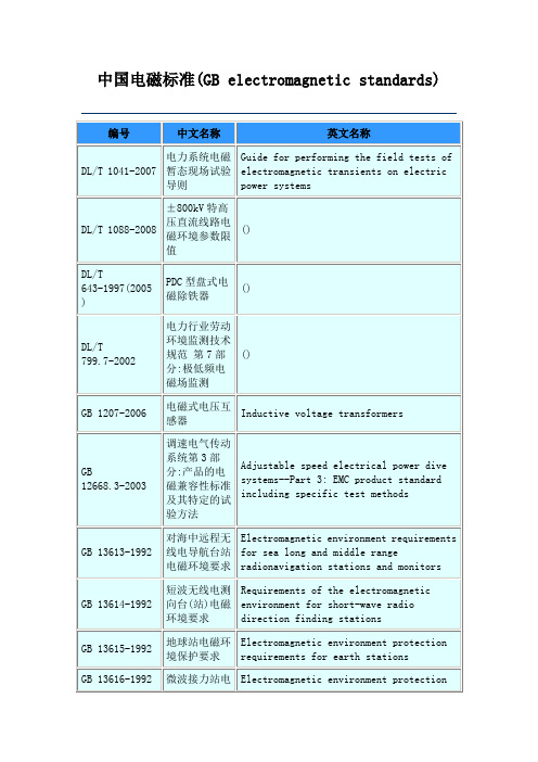
对空情报雷达站电磁环境防护要求
Requirements of electromagnetic environment protection for air defense surveillance radar station
GB 13836-2000
电视和声音信号电缆分配系统第2部分:设备的电磁兼容
GB 13616-1992
微波接力站电磁环境保护要求
Electromagnetic environment protectionrequirements for microwave relay stations
GB 13617-1992
短波无线电收信台(站)电磁环境要求
Electromagnetic environment requirements for shortwave radio receiving stations
()
GB 19286-2003
电信网络设备的电磁兼容性要求及测量方法
Electromagnetic compatibility requirement and measurement methods for telecommunication network equipment
GB 19483-2004
短波无线电测向台(站)电磁环境要求
Requirements of the electromagnetic environment for short-wave radio direction finding stations
GB 13615-1992
地球站电磁环境保护要求
Electromagnetic environment protection requirements for earth stations
EMC标准和规范
4. 专用产品EMC标准
专用产品EMC标准是关于特定产品、系统或设施而制定 的EMC标准,根据这些产品特性必须考虑一些专门的条 件,它们采用的规则和系列产品必须考虑一些专门的条 件,它们采用的规则和系列产品EMC标准相同。专用产品 EMC标准应比系列产品EMC标准优先采用。
IEC标准编号 EC/TR3 61000-l-l IEC/TR3 61000-2-l IEC 61000-2-2 IEC/TR3 61000-2-3 IEC 61000-2-4
环境的描述公用供电系统中低频传导骚扰和信号传输的电磁环 境
Description of the environment -Electromagnetic environment for low-frequency conducted disturbances and signalling in public power supply systems
IEC 61000-3-3
IEC/TR2 61000-3-4
IEC/TR2 61000-3-5
IEC/TR3 61000-3-6
IEC/TR3 61000-3-7
IEC/TR3 61000-3-8
第3部分 限值 Limits
1995-03 1997—09 1998-02 1998-04
Ed.1.2 1994-12
1.6 EMC标准与规范
标准是一个一般性的导则或预期要满 足的准则,由它可以导出各种规范;
规范是一个包含某类设备详细说明和 详细数据,必须遵守的文件.
EMC标准与规范的内容:
规定名词术语; 规定电磁骚扰发射限值和抗扰度要求; 规定统一的试验方法; 规定EMC控制方法或设计规范.
EMC标准与规范的类型:
Immunity_requirements
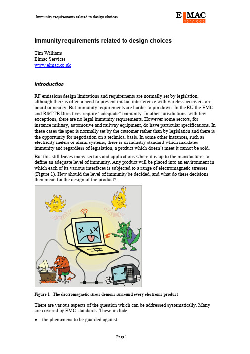
Immunity requirements related to design choicesTim WilliamsElmac ServicesIntroductionRF emissions design limitations and requirements are normally set by legislation, although there is often a need to prevent mutual interference with wireless receivers on-board or nearby. But immunity requirements are harder to pin down. In the EU the EMC and R&TTE Directives require “adequate” immunity. In other jurisdictions, with few exceptions, there are no legal immunity requirements. However some sectors, for instance military, automotive and railway equipment, do have particular specifications. In these cases the spec is normally set by the customer rather than by legislation and there is the opportunity for negotiation on a technical basis. In some other instances, such as electricity meters or alarm systems, there is an industry standard which mandates immunity and regardless of legislation, a product which doesn’t meet it cannot be sold. But this still leaves many sectors and applications where it is up to the manufacturer to define an adequate level of immunity. Any product will be placed into an environment in which each of its various interfaces is subjected to a range of electromagnetic stresses (Figure 1). How should the level of immunity be decided, and what do these decisions then mean for the design of the product?Figure 1 The electromagnetic stress demons surround every electronic productThere are various aspects of the question which can be addressed systematically. Many are covered by EMC standards. These include:•the phenomena to be guarded against•the levels of applied stress for each phenomenon, and the ports to which it is applied•the performance criterion to be applied, and the operating mode(s) to be verified, in each caseThese headings form the basis for a test plan, which can and should be laid down at an early stage of a new design. But they should also guide the design team in their choice of mitigation techniques. This article looks at the way design choices can be married to the immunity requirements: the critical question for designers is always, how much EMC mitigation is enough? We can partition the problem, on the basis of phenomena, into continuous stresses (application of criterion A in the generic standards) and transient stresses (criterion B), with a mention also of low frequency immunity issues. Continuous phenomena: conducted and radiated RFAs a general rule, and one that is subject to exceptions, digital circuits are less susceptible to continuous RF while analogue circuits are more so. There are quite a few designers of purely digital circuits who treat the RF immunity tests with disdain, because they’ve never seen a failure. But analogue designers are (or should be) far more familiar with RF susceptibilities and always need to take design precautions. These are principally of two sorts, mirroring the two routes of coupling: via connected cables, and directly with the circuit.Cable coupling: interface protectionThe standard cable-coupled RF immunity test of IEC 61000-4-6 requires an injected level, typically of 3V or 10V open circuit voltage from a source impedance of 150Ω, in common mode into each interface to be tested. The test frequency range is 150kHz –80MHz, with a possible extension up to 230MHz; from the design point of view, you can assume that cable-coupled RF must be anticipated certainly up to this higher frequency [1]. The real RF environment is quite well represented by this requirement. MF (300kHz-3MHz) and HF (3MHz-30MHz) interference levels of several volts are relatively rare, but possible if a product is located near a broadcast or amateur-band transmitter and connected to a long cable. Above 30MHz, sources are more likely to be mobile transmitters in the neighbourhood, but these can quite easily create common-mode cable voltages of a few volts if they are within a few metres. Military products, mounted on the same platform (aircraft, ship or vehicle) as HF transmitters can see substantially higher levels; the DEF STAN 59-411 DCS02 test for instance can inject 115dBµA (560mA, or 56V in a 100Ω system) over 10 – 100MHz for safety critical aircraft equipment.These tests mean that every cable interface needs RF common mode filtering or screening, effective up to at least 200MHz and perhaps beyond. This is not just on interfaces that will be tested; even untested interfaces will see some level of common mode RF current, as Figure 2 makes plain. Plus of course, in the radiated case, all connected cables are subjected to the stress. The current injected into any one interface must flow back to its source through some common mode path, and this will typically include every other connected cable. The path(s) taken by the disturbance will be determined by the various ratios of common mode impedances both within and outside the product. Only if the product’s chassis is well grounded, and if every tested interface is well filtered to this chassis, can untested interfaces be ignored.Figure 2 Injected RF passes from the tested port through other ports to groundThe choice of filtering or screening the cable interfaces depends on how much control you can exert over the connected cables, what signals they carry, and the cost constraints on the product. Generally it is preferable to rely on filtering alone, because screenedcables are more expensive and require greater effort on the part of the installer; they also need a proper ground structure for the screen connection. But the advantage of a screen is that, when correctly implemented, it can attenuate interference by several tens of dB more than a simple filter can achieve, especially important if the interference is in the same frequency range as the wanted signal. Video and wideband data circuits fall into this category.The RF common mode filter can be configured to be high impedance or low impedance.Low impedance implies capacitive filtering to chassis; high impedance means a common mode choke (Figure 3). One technique will reduce current flow and leave a high common mode voltage at the interface, but without this voltage affecting the circuit. The othertechnique diverts current into a harmless route and leaves a low common mode voltage at the interface, but only as long as the diversionary route is itself low impedance. A combination of both is of course possible, and necessary if the attenuation of a single stage is inadequate. The choice depends firstly on the possibility of implementation (for instance, parallel capacitors are ruled out for high-speed interfaces) and then on the native impedance of the unfiltered interface – a high-impedance input will not benefit much from a series choke, while a low-impedance input won’t be helped much bycapacitance. The choice is also affected by whether or not a particular interface expects to see EFT/Burst transients (see later), as a simple choke at the interface may not be able to cope with high voltage bursts applied directly in series with it.Figure 3 High versus low common mode impedanceHigh impedanceLow impedanceTo a first order, the applied stress level sets the required common mode rejection for the input filtering, compared to the level of the wanted signal (see Figure 4). For instance, if a video channel can cope with 30mV before in-band interference becomes obtrusive, then a rejection of 40dB against 3V is needed. But classical video connections are generally single-ended rather than differential, and single-ended filtering can’t separate in-band interference from the signal. Hence screening is usually required, and then the screening attenuation is dominated by the transfer impedance at the shield connection to chassis.Figure 4 Equivalent circuit of voltage injection at inputsOn the other hand, balanced interfaces such as for data communications can use effective in-band common mode filtering; and low-frequency single ended interfaces for audio or transducers can be effectively filtered against RF from150kHz upwards. Imperfections tend to upset the neat equivalent circuits shown in Figure 4: component imbalance, resonances, and inadequate layout. The last of these will affect either the ground path or the effectiveness of the filter components, or both. Too much inductance in the ground connection will limit the attenuation of any capacitive filtering, and too much coupling across a common mode choke will limit its impedance. Resonances can be related to layout imperfections, self-resonance in filter components or spurious frequency responses in operational circuits. Sometimes they can be modelled into the equivalent circuit if the causal parameters are known, but especially at higher frequencies they can be impossible to anticipate. However, it is rare for such unintentional resonances to have a high Q, and this means that their impact on the circuit’s RF response is moderate. In many cases their effect can be mitigated by designing an extra 20dB into the interface protection, over what is required according to the simple equivalent circuit.For balanced circuits, the filter components can influence the common-to-differential mode conversion. Common mode RF attenuation becomes increasingly effective as the frequency rises, but at the lower frequencies, there is the threat of conversion of the common mode disturbance into a differential mode input, which of course cannot be rejected by the input amplifier.If the entire circuit is perfectly balanced, then this conversion does not occur. But actually maintaining balance requires that every component in one half of the circuitexactly mirrors that in the other: not only its intended value but also the values of its unwanted parasitics. This is not easy to achieve. In the common mode choke, the construction of the windings will cause a small degree of imbalance in the inductance of each half and in the stray capacitance associated with each half, figures which are never quoted in the data for such parts. But if discrete components are used for the capacitors, their tolerances are usually the dominant source of imbalance: depending on their construction, COG ceramic capacitors are typically ±5% or ±10%, while X7R can easily be ±20%. Some capacitor types, intended specifically as I/O filters, have tolerances as wide as +50% –20%. If you are designing a capacitor filter for a balanced circuit, be sure to evaluate the effect of worst case tolerances on the common-to-differential mode conversion across the frequency range.Radiated coupling: circuit design, layout and shieldingRadiated RF interference couples principally via connected cables up to frequencies of the order of 200MHz, when cable lengths are closer to quarter-wavelength multiples than are the structural components of the product, including its PCBs. But a quarter wavelength at 250MHz is 30cm, and so for typical product sizes RF coupling becomes more efficient with structures than with cables above this frequency. RF coupling directly with internal structures cannot be dealt with by interface filtering. So for these frequencies, mitigation techniques must concentrate on•Good PCB and internal layout•Bandwidth limiting at the circuit level•Shielding, either of the whole unit or subsections of itStandard PCB layout principles to control RF emissions are also good for immunity: foremost among these is the ground plane [2][3]. But we are not so much concerned with tracks carrying intentional HF currents, as those which carry low-level broadband signals that will be affected by the directly induced disturbance. The protection afforded by the ground plane must be extended to these.Bandwidth limiting is a simple but vital technique for any low frequency analogue circuit (Figure 5). Many analogue amplifiers will respond to RF, especially if it is applied across their input pins, well beyond their intended operating frequency [4]. It’s therefore necessary to make sure that such RF doesn’t appear anywhere in the circuit where it could create a non-linear response, as Figure 5 shows; RC filters and series buffer resistors are a standard technique for this, as is decoupling of power supplies and reference voltages using both series and parallel components. The time constants of the filters should be chosen to have no effect on the signal circuit but to adequately attenuate the unwanted interference; a simple RC filter shows a 20dB/decade increasing attenuation above its corner frequency of 1/2πRC, so for instance a 220Ω + 10nF network will have little effect below 70kHz but give better than 40dB above 7 MHz (although parasitic L in series with the C, and C across the R, will kick in and limit the attenuation at higher frequencies).Figure 5 Circuit methods for bandwidth limitationAs with cable coupling, an estimate of induced RF in known sensitive parts of an unshielded circuit can be made from a knowledge of simple antenna structures and applied stress levels, so that the required degree of filtering can be predicted to an order of magnitude. And also as with cable coupling, resonances in the structures, and parasitics and undetected layout mistakes, will limit the effectiveness of such predictions. Faraday’s law can be invoked to give an order of magnitude estimate of voltage induced into a circuit of a particular area. So for instance, take a 5cm long track placed 0.5mm above a continuous ground plane as might be found on a standard four-layer board (Figure 6). We have to make the initial assumption that the impinging field is a plane wave with the free-space impedance of 377 ohms. Then a 10V/m field has a magnetic component of (10/377) = 27mA/m or 34⋅10-9 Tesla (1A/m ≡ 4π⋅10-7 T in non-magnetic media).Figure 6 RF voltages induced into a circuit by direct couplingFaraday’s law states that the induced voltageV=-A ⋅ dB/dt where A is the loop area in m2 and B is the magnetic fluxdensity in Tesla.dB/dt is frequency dependent and can be given by 2πF⋅B for a sinusoidal signal (F in Hz). So to take the above geometry and incoming field at two different frequencies, say 50MHz and 600MHz, we have an induced interference voltage (ignoring the minus sign) assuming maximum coupling ofV50MHz=25⋅10-6⋅ 2π⋅50⋅106⋅ 34⋅10-9=0.267mVV600MHz=25⋅10-6⋅ 2π⋅600⋅106⋅ 34⋅10-9= 3.2mVThis calculation ignores the electric field coupling, which is acceptable for low impedance circuits and small structures, and it also becomes invalid for higher frequencies where the structure dimensions are significant with respect to a quarter wavelength: in FR4 fibreglass with a relative permittivity of 4.5, a quarter wavelength at 600MHz is 3⋅108/(600⋅106⋅ 4 ⋅√4.5) = 11.8cm. Even so, it demonstrates why it is that digital circuits on surface-mount multilayer boards are rarely affected by RF interference at the commercial field strength levels – a few millivolts is neither here nor there to a digital signal, though it could be to a low-level ADC or audio or video amplifier. Shielding should really be a method of last resort, when filtering and layout control are inadequate or unavailable. This is often not so much because of direct coupling to PCBs, as because internal wiring between PCBs has not been sufficiently protected. Such wiring should in best practice be treated as the PCB tracks themselves, and provided with a ground plane structure – double sided flexi connectors are a quite simple way of doing this. Alternatively, treat each internal board-to-board connection as if it were external, and implement filtering for VHF and above on interfaces to these connections. Small ferrite chips and low value three-terminal capacitors are good for this purpose.High levels of RF stress (30V/m and above) as are found in military or automotive applications, and/or analogue circuits that are sensitive at the sub-millivolt level, normally mandate shielding. Important design issues for shielding are mostly mechanical and centre around minimising apertures in the shield. The larger the maximum aperture dimension, the less effective the shield becomes; and whatever you do, such apertures (for instance ventilation slots) should not be placed anywhere near sensitive circuits, either components or tracks.RF immunity of digital circuitsGenerally, digital circuits are more robust against RF interference than analogue, as mentioned above. When RF susceptibilities do happen, they can be divided into two types – timing effects, and spurious transitions (Figure 7).As an increasing RF induced disturbance is superimposed on a digital signal the first effect that occurs is that the intentional signal transitions are modulated by the interference and timing jitter occurs. Therefore, a digital design that is not critically dependent on timing accuracy will be more immune than one in which timing has been “tuned” for maximum performance.Beyond this, higher levels of interference will push the node voltage to a point at which spurious transitions occur. Maximum susceptibility will be when the interference is in-phase at the same frequency as any ringing on the intentional transitions. The unwanted transitions are likely to propagate through the digital network causing corruption of data transfer and swift failure of the digital program. The exact point at which this happens will be a function both of coincidence in timing and the levels induced in particular nodes; trying to detect and deal with the problem on a node-by-node basis will usually be unrewarding, and so it is necessary to implement good layout practice in all the active parts of the digital circuit. At the same time, good signal integrity design – proper decoupling, 0V impedance control, transmission line routing and matching – will improve immunity, since signal nodes with marginal integrity will be inherently more affected by induced superimposed RF.Without interference With interferenceFigure 7 RF interference effects on digital signalsTransient phenomena: ESD, burst and surgeBy contrast with the above discussion, transient immunity is more of a problem for digital than analogue circuits. Nanosecond-period spikes occur in the same time frame as a digital clock cycle and can therefore corrupt a single data transfer, resulting in complete failure of the program. In an analogue application, the same disturbance may be completely ignored by the signal circuit simply because it can’t respond fast enough. On the other hand, bursts of short duration pulses lasting for milliseconds may still have enough energy to disturb or overload some analogue functions, particularly if their bandwidth is not sufficiently limited. And in either case, surge transients may cause not only disruption but actual circuit damage.Electrostatic dischargeIt is common for ESD to be a problem for most digital designs. There are two diametrically opposed techniques for dealing with the ESD threat:•Accept that an ESD strike will occur to any exposed metalwork, and divert it away from the operating circuit;•Design the housing of the product to avoid an ESD strike altogether.In both cases, it is necessary to ensure that the circuit can cope with radiated ESD transients due to nearby events, which means that any potentially susceptible circuit node is protected by good layout and if necessary by filtering. Any edge-triggered circuit is potentially affected by the ESD; the leading edge of the waveform can reach several amps in less than a nanosecond, meaning that the rise time is 109–1010 amps/second. Interrupts, and particularly resets should be treated as critical. Layout of the track which carries the signal should ensure that it is protected by a continuous ground plane. Where the signal connects to an input pin, such as the RESET of any processor, it would be sensible to include an RC filter, with a time constant of 100-500ns: a series 1k resistor and a 100pF capacitor between the sensitive pin and its nearest 0V pin is fine.Power supply decoupling must not be ignored; it’s not just an emissions requirement. Transient variations in the power rail voltage can cause functional corruption, and an ESD pulse can create such a variation. Decoupling, with the same HF principles as for emissions, is essential to prevent such variations.ESD-specific interface protection should only be mandatory if strikes directly toconnector pins are intended or likely in the real environment. However, as with RF, ESD current can flow out through interfaces as a result of strikes elsewhere on the product (see Figure 2). Some protection of such interfaces is therefore advisable. There are various types of protection device which should be selected on the basis of application: fast data communications interfaces such as USB or LVDS will need low capacitance devices,while power supplies can cope with much higher capacitance and leakage.Figure 8 ESD interface protection optionsRemember that the same interface will also potentially be subjected to volts ofcontinuous RF, and the ESD protection scheme should be integrated with the RFprotection. In the simplest case, this means that RF filtering capacitance can be paralleled with a zener-type breakdown device to prevent overvoltage on this capacitance.Unfortunately, such protection diodes can rectify the applied RF and may in fact make RF immunity worse. Therefore the RF filter attenuation should be designed with the intention of keeping voltages across these diodes below their threshold of non-linearity.The actual voltage that will appear across the interface will not be anything like the full ESD voltage: it will be attenuated by a complex circuit of impedance dividers involving the capacitance and series impedance of the source, the capacitance of the interface filtering, and the various series impedances between the source and the ground return path. With a full knowledge of these impedances it would be possible to model thevoltage and current waveforms at critical points, but diagnostic and confidence testing is quicker, cheaper and usually more reliable.Enclosure design has to respect the ability of the ESD strike to find its own path.Apertures and discontinuities represent inductance and hence a high impedance to the current; but conversely, short-distance gaps can be bridged by a high voltage arc.Designing a plastic case to avoid discharges involves ensuring that there are no creepage paths from the outside to any conductive points inside. Any floating metalwork(including unconnected copper on the PCB) can acquire a high static charge due to ESD events, which may then create internal discharges; all such metallic parts should be connected, typically to chassis or to 0V.steering diodesavalanche (zener) diodemultilayer varistorElectrical fast transient burstsEFT bursts are easily dealt with if capacitive filtering to a solid chassis metalwork is available for all tested interfaces. Typical EFT/B failures are due to an inadequate orunavailable interface ground reference. The most recent second edition of IEC 61000-4-4applies the burst always in common mode with respect to the test set-up ground plane;the first edition didn’t make this clear, and so some testers would apply the burst separately to mains L, N and E individually. Particularly with power supplysusceptibilities, this could cause different failure mechanisms compared to the straight common mode application.Using the second edition, mains EFT/B transients will be applied to any protective earth (PE) terminal in parallel with live and neutral, so a path must be provided back to the outside world which doesn’t involve the circuit. The PE will typically be connected to chassis metalwork which will therefore be carrying the full burst voltage. Not much burst energy will appear between the chassis and the circuit, but it will stress any unprotected (filtered or screened) interfaces, and stray capacitance from the circuit to the outside test ground plane will also play a part (Figure 9). This means that circuit-level transientprotection is as important for EFT/B as it is for ESD, and the same techniques are useful for both.High frequency filtering capacitors at some point before any active circuitry are always needed to cope with both EFT/B and RF interference on the power supply. For signal interfaces, the chosen method of protection (high impedance choke versus lowimpedance capacitors) will depend on whether the protection components are able to tolerate the expected applied levels. The typical residential-environment level of 500V can usually be blocked by a choke circuit, but higher industrial levels of 1kV will need a more robust approach, involving parallel capacitance, protection diodes or isolation.Figure 9 Equivalent circuits for EFT/B application according to IEC 61000-4-4Signal port application PS CCTPS CCTMainsEUTMains port applicationSurgeSurge protection is principally a matter of ensuring that the high voltage applied (from a low source impedance) during a surge event is prevented from damaging active circuitry at the power supply or signal interfaces. This can be achieved either by designing an interface to tolerate a high voltage – using over-rated components, series resistors and steering diodes, or transformer or opto-isolation – or by clamping the surge voltage itself to a tolerable level. Over-rating may be feasible if the surge voltage is no more than500V, but gets rapidly impractical for surges in excess of 1kV, which may be applied in common mode or differentially. If it is employed, not just the component ratings but also the creepage and clearance distances across PCB tracks and other conductors that may be exposed to the full voltage must be investigated and adequately controlled.Surge clamping is an effective technique but requires the clamp devices to be correctly positioned and matched to the expected surge energy and voltage. The common IEC 61000-4-5 test has a predictable energy (Figure 10), but designing only for this doesn’t guarantee protection under all real-life conditions, and some over-specification is advisable. The most important design criterion for the surge protection device is that the voltage developed across it by the peak surge current is still less than can be withstood by the downstream circuitry. This can easily be twice the rated voltage of the device, which is typically quoted at 1mA (all devices have published curves which show the voltage-current profile); which is to say that for instance a 39V part, to adequately protect a 24V ±25% supply, demands a downstream voltage withstand of at least 80V and preferably 100V. Then the size of the protection device is determined by the maximum energy that can be deposited in it by a surge of a given waveshape and voltage from a given source impedance. The IEC 61000-4-5 surge comes from a source impedance of 2, 12 or 42 ohms depending on whether it is applied across mains L-N, mains LN-E, or signal lines.This is the energy available to be delivered from the IEC 61000-4-5generator into a matched resistive load, which is not the same aswould be delivered into a non-linear clamping deviceFigure 10 Surge energy versus applied voltageIn some applications it is feasible to include some extra series impedance at the interface, which allows the energy rating of the surge protector to be reduced, although this is not usually possible for power supplies. But such a series impedance will be exposed to the lion’s share of the surge voltage, assuming the clamp works correctly, and this often means that providing the impedance is not trivial; for instance, a 1kV peak surge applied through a few hundred ohms to that 39V surge protector will drop around 950V across。
CQC 强制性产品认证变更申请书
申请编号: 生产厂编号:Application No: Factory No:CCC认证变更申请书Application Form for Change of CCC Certification申请日期/Date:产品类别/Product sort:中国质量认证中心China Quality Certification Centre1.认证委托人/Applicant:1.1认证委托人名称/Name of Applicant:1.2 付款人名称、地址/Name 、Address of Payer:1.3认证委托人地址、邮编/Address and post code of Applicant:1.4证书邮寄地址、邮编/Address and post code of certificatemailing:批准书/各类通知书邮寄地址、邮编/Address and post code of approving for change of certification or notice of suspension, withdrawal, cancellation or resumption:1.5 组织机构代码/Organization Code:1.6联系人/Contact Person:1.7电话/ Telephone: 1.8传真/Fax:1.9电子邮件/E-mail:1.10 移动电话/Mobile phone:2. 代理机构或中国办事处/Name of Agent or office in China:2.1 代理机构/中国办事处名称/ Name of Agent or office in China:2.2 联系人/Contact Person:2.3电话/ Telephone:2.4传真/Fax:2.5电子邮件/E-mail:2.6 移动电话/Mobile phone:3. 生产者(制造商)/Manufacturer(where the equipment is produced):3.1生产者(制造商)名称/Name of Manufacturer:3.2生产者(制造商)地址/Address of Manufacturer:3.3联系人/Contact Person:3.4 电话/ Telephone: 3.5 传真/Fax:3.6 电子邮件/E-mail:3.7 移动电话/Mobile phone:4. 生产企业/Factory(where the equipment is produced):4.1生产企业名称/Name of factory:4.2生产企业地址、邮编/Address and post code of factory:4.3联系人/Contact Person:4.4电子邮件/E-mail: 4.5电话/ Telephone:4.6传真/Fax: 4.7移动电话/Mobile phone:4.8工厂编号/Factory Number :5.产品名称/Name of Production:6.产品类别/Product Sort :7.产品商标/Trade mark:8.型号和规格(中文)/Model and specification: 型号和规格(英文)/Model and specification:9.产品认证依据/Standards of product certification :10. 申请认证的产品是否有CB 测试证书/Has the applying equipment been awardedthe CB Test Certificate:是/Yes 否/No 如果有,给出CB 测试证书的编号和获证日期/If “Yes”, give the number and date of theCB Test Certificate:a. CB 证书号/No. Of CB Certificate:b. 获证日期/Issued Date:c. 颁发CB 测试证书的认证机构/Name of the NCB issuing the CB Test Certificate :11、申请CCC 认证的同时,是否申请CB 测试证书/ If to apply CB Certificate When apply CCC Certification:是/Yes 否/No 12、说明生产企业是否有同类产品获得过CCC 证书,如果有,请列出证书编号。
emc rs测试 电源判定标准
EMC (Electromagnetic Compatibility)是指电器设备在电磁环境中实现正常工作,并不会对周围的其他设备造成干扰。
而电源判定标准(Power Determination Standard) 则是用来评估电器设备在电源方面的性能和稳定性。
在工业生产中,对于电器设备的EMC和电源性能要求越来越高,因此EMC RS测试成为了一项必不可少的工作。
EMC RS测试主要是对电器设备进行各种电磁兼容测试,包括辐射测试、传导测试、耐受性测试等,以及对电器设备在不同电源条件下的稳定性和性能进行评估。
在进行EMC RS测试时,需要严格符合国际电工委员会 (IEC)、国际标准化组织 (ISO) 和其他相关组织的标准,以确保测试结果的准确性和可靠性。
在进行EMC RS测试时,首先需要进行辐射测试,即测量电器设备所产生的电磁辐射是否符合规定的标准。
这项测试通常包括辐射抑制测试和电磁辐射测量,通过这些测试可以评估电器设备在正常工作状态下对周围电磁环境的影响程度。
其次是传导测试,主要是检测电器设备对外部电磁干扰的抵抗能力,包括电源线传导干扰和接地传导干扰测试,以保证电器设备在各种外部干扰条件下都能正常工作。
最后是耐受性测试,即对电器设备在不同的电源条件下进行测试,包括电压波动测试和断电恢复测试,以确保电器设备在异常电源条件下仍能保持稳定和正常工作。
对于电源判定标准,主要是评估电器设备在各种电源条件下的性能和稳定性。
这包括电源波动测试、过载能力测试、电源转换效率测试等,以及对电器设备在不同工作环境下的稳定性进行评估。
通过这些测试,可以直观地了解电器设备对电源条件的要求和对于电源干扰的抵抗能力,为生产和应用提供可靠的参考数据。
在我看来,EMC RS测试和电源判定标准的重要性不言而喻。
在现代科技和工业生产中,电器设备的稳定性和性能对于整个生产链条都至关重要。
通过严格的EMC RS测试和电源判定标准评估,可以确保电器设备在各种工作环境和电源条件下都能保持稳定和正常工作,为生产、应用和用户提供可靠的保障。
- 1、下载文档前请自行甄别文档内容的完整性,平台不提供额外的编辑、内容补充、找答案等附加服务。
- 2、"仅部分预览"的文档,不可在线预览部分如存在完整性等问题,可反馈申请退款(可完整预览的文档不适用该条件!)。
- 3、如文档侵犯您的权益,请联系客服反馈,我们会尽快为您处理(人工客服工作时间:9:00-18:30)。
EMC Standards and Their Application By Dag BjörklöfETL SEMKO (Kista, Sweden)Intertek Testing ServicesWithout EMC—no market access! Yes, that is the fundamental concept for manufacturers of electrical apparatus and systems to remember. It is therefore necessary to stay current on EMC requirements and standards and to try to understand how each applies to different types of equipment.Regulations may be mandatory, like U.S. FCC requirements and European EC Directives, or voluntary, like VCCI approval in Japan. In either case, following EMC regulations may impart a market advantage.Standards are voluntary to use but are recommended as a reference for verification of compliance with regulations. Basic standards describe test procedures, and in some cases test instrumentation and calibration techniques, while more specific product or application standards usually define limits, severity levels, and compliance criteria. This article provides an overview of EMC standards and their use for verifying compliance with regulations. Electromagnetic Compatibility—Some Fundamental Concept sEMC stands for electromagnetic compatibility and is defined as the ability of equipment to function satisfactorily in its electromagnetic environment without introducing intolerable disturbances to anything in that environment. EMC requirements concern two basic concepts: emissions and immunity or susceptibility.Electromagnetic disturbance is any phenomenon that may degrade the performance of a device, equipment, or system, or adversely affect living or inert matter.Electromagnetic interference (EMI) is the degradation of the performance of a device, transmission channel, or system caused by an electromagnetic disturbance. In certain parts of the world, "EMI" is used to characterize emissions. This may lead to confusion when it comes to the characterization of immunity, which is sometimes called EMC!Electromagnetic disturbances can be conducted or radiated, and the emissions and immunity requirements are referred to in military standards (MIL-STD 461/462) as CE/RE (conducted emission/radiated emission) and CS/RS (conducted susceptibility/radiated susceptibility), respectively. Disturbances may represent low-frequency (LF) and/or high-frequency (HF) phenomena, as well as broadband and/or narrowband. Broadband disturbances can originate from commutator motors, ignition systems, arcwelding equipment, etc.; narrowband from digital electronic circuitry, switched-mode power supplies, and radio communication equipment. Computers have often been reported to cause interference with radio services, including police, aeronautical and broadcast services. On the other hand, radio transmission by a high-frequency carrier, such as a 900 MHz cellular or a 1.8 GHz DCS, can cause problems in computers and all electrical circuits because the carriers are easily picked up by cables and apertures functioning as antennas and are demodulated in electronic circuits by different nonlinear electromagnetic phenomena.To really understand how electromagnetic disturbances emanate, propagate, and influence electrical systems, one must have a thorough knowledge of electromagnetic field theory and high-frequency phenomena. EMC represents a broad field of technology and may represent a new subject for many manufacturers of electrical products. However, if one follows certain rules of thumb regarding wiring, PCB layout, grounding and shielding, and usage of RFI suppression components, it is not difficult to cope with different EMC standards and regulations.In industry, it is assumed that electronic control systems can be used in conjunction with interfering switching operations, motor drives, high-frequency ovens, welding equipment, etc. In a car, electronic automatic systems must function when we use our mobile phone or meet other vehicles (with interferingignition systems). An electronically controlled wheelchair is presumed to function normally even when the person sitting in the chair uses a mobile phone or a portable PC. We demand that life-supporting electromedical apparatus in a hospital function safely even near high-frequency—radiating surgical equipment.U.S. RequirementsThe general EMC requirements in the U.S. are set by the Federal Communications Commission (FCC), while the Food and Drug Administration (FDA) regulates medical products. Mandatory FCC requirements primarily concern computing devices, defined as any electronic device or system that generates and uses timing pulses at a rate in excess of 9000 cycles per second and uses digital techniques. FCC Part 15 covers radio frequency devices capable of emitting RF energy in the range of 9 kHz—200 GHz. Testing should be done according to ANSI C63.4-1992.Part 18 covers industrial, scientific, and medical (ISM) equipment (Figure 1), defined as any device that uses radio waves for industrial, scientific, or medical purposes and is not intended for radio communications. While most FCC regulations only concern emissions, FDA also requires immunity for certain life-support equipment. FCC Parts 15 and 18 include regulations as well as technical aspects and limits. FCC Part 68, which governs the technicalrequirements for registration of telecom terminal equipment, includes lightning surge tests (surge immunity).Figure 1. Required frequency range ofradiated measurements—ISM.FCC Part 15 currently has three different procedures for showing conformance:∙Verification, where the manufacturer or the importer files a test report showing compliance.∙Certification, which requires a review of the application by the FCC, and the use of a unique FCC identification number.∙Declaration of Conformity (DoC), which requires that tests are performed by a test lab accredited by A2LA or NVLAP (other accredited labs may also be accepted).∙The following represents an example of the FCC's classification system, where the correct administrative procedure is listed according toproduct type (Class A refers to nonconsumer products, Class B toconsumer products):∙Personal computers and peripherals (Class B): Certification or DoC.∙Cpu boards and internal power supplies used with personal computers (Class B): Certification or DoC.∙External switching power supplies (Class A and B): Verification.The FCC is currently reviewing these procedures with the aim of simplifying them by reducing the number of categories.EU RequirementsThe European EMC Directive, 89/336/EEC, sets out the legal requirements on EMC for principally all electric/electronic equipment to be placed or used in the Common Market/European Economic Area. The European legislation covers emissions as well as immunity.The EMC requirements are valid for apparatus and systems placed on the market as complete units. Components such as resistors, transistors, or display units are not included. However, components with a direct function to the end-user, like plug-in PC boards, are regarded as equivalent to apparatus and have to follow the same rules (see Table I).Scope ofFCC EU EMCRegulation—Device TypesUnintentional Radiators Appliances and/ordigital circuitryinsideNo YesAutomotive digital electronics NoYes, Auto EMCDirectiveDevices with power<6 n WNo NoComponents No, except cpuboards andpower suppliesYes, if it has adirect functionElectromechanical No Yes, except for induction motorsKits No, except TV interface deviceYesFluorescent lamps, fixtures No (unless RF ballast)YesMarine digital electronics NoYes, MarineEquipmentDirectiveMedical digital devices No Yes, Active Implantable, or Medical Devices DirectivesTest equipment No Yes Controls in industrialplantsNo Yes Battery operated clock<1.705 MHzNo Yes Digital devices, PCs,peripheralsYes Yes Intentional RadiatorsAmateur radio transmitters No, exceptcommercialNo, except EMCfor commercialpower amplifiers transmittersShort-range devices Yes, Part 15ETS 300, 220, 328, 330, 440, 445, or national rulesHigh power transmitters Yes, other FCCPartsETSI or nationalrulesTable I. Scope of FCC and EU EMC regulations forunintentional and intentional radiators.New EEC Directives only set out essential requirements and legal aspects (New Approach). Technical aspects are dealt with in specific standards, the application of which is voluntary. These standards are developed by specific bodies, such as CENELEC or ETSI, and are harmonized to the directives by the action of the European Commission. The EMC Directive itself, however, is based on a presumption principle, which means that a product that meets the requirements of the harmonized standards is also presumed to meet the essential requirements of the EMC Directive.StandardizationUnder the General Agreement on Tariffs and Trade (GATT) and its successor, the World Trade Organization (WTO), member countries are obliged to adopt international standards for national use wherever possible. International standards concerning EMC are primarily developed by the International Electrotechnical Commission (IEC) and the International Special Committee on Radio Interference (CISPR). The new extensive series developed by IEC includesIEC 61000-1—Introduction, terms, and conditions.∙IEC 61000-2—Classification of electromagnetic environments.∙IEC 61000-3—Limits and disturbance levels.∙IEC 61000-4—Testing and measurement techniques.∙IEC 61000-5—Installation and mitigation guidelines.∙IEC 61000-6—Generic standards.Some specific EMC standards have also been published by the International Organization for Standardization (ISO). North American EMC standards are published by the FCC, the American National Standards Institute (ANSI), and the Institute of Electrical and Electronics Engineers (IEEE). Private standards are submitted by Bellcore (for telecom equipment), the Society of Automotive Engineers (SAE) and automotive manufacturers, and the U.S. Department of Defense.European EN standards concerning EMC are developed by the European Committee for Electrotechnical Standardization (CENELEC).Regulations and standards concerning telecom and radio transmitting equipment are published by the International Telecommunications Union (ITU) and the European Telecommunications Standards Institute (ETSI). International and European EMC standards are to a great extent becoming harmonized, due to the fact that many EN standards are based on IEC and/or CISPR standards. There are also similarities between international and U.S. standards, though they are not equivalent. Figure 2 shows some intercompatibility problems between similar emission standards (FCC Part 15 J and CISPR 22 limits, respectively, measured at a distance of 10 m). FCC,however, accepts conformity to CISPR 22: 1985 as an alternative to FCC Part 15 (sections 15.107 and 15.109).Figure 2. Emission limits compared at ameasuring distance of 10 m.Figure 3. Required frequency range ofconducted measurements.EMC standards are continuously being developed and revised, and the standards "jungle" sometimes seems a bit difficult to get through. It is therefore important to keep track of standards' publication dates, in addition to knowing if a new standard is to be expected in the near future and when an old standard is no longer valid. The following dates are of specific interest in regard to a standard: date of publication (dop) and date of withdrawal (dow) of a conflicting(earlier) standard. Draft standards are sometimes called preliminary, for example prETS or prEN. Temporary EN standards are called ENV.Standard RequirementsStandards are principally divided into the following main groups:Generic/General StandardsGeneric standards refer to the electromagnetic environment in which the apparatus/system is to be used. General standards concern groups of equipment used for general applications in a specific environment, like general telecom equipment and medical and laboratory equipment.Basic StandardsBasic standards describe measuring methods and, in some cases, interference levels as well as limits. One of these is the standard series IEC 801-X for process industrial applications, which has been converted into a general series of basic standards, IEC 61000-4-X, which were then translated into European standards as EN 61000-4-X.Product and Product Family StandardsThese are applicable for specific product types, which are specified within the scope of the standard.In addition to these standard documents, there are also standards offering guidance on installation techniques, or a code of practice, for example the IEC 61000 series, Part 5 (IEC 61000-5-X).EMC Standards ClassificationGeneric standards have two environmental classes:1. Residential, commercial, and light industrial environments, including domestic, office, laboratory, and light industrial environments where the apparatus or system is connected to the public mains.2. Industrial environments, meaning "heavy" industrial environments with separate transformer stations for mains supply, usually with equipment spread over some distance.This simplified view of the world as one of two categories does not hold true in all cases. There are so-called gray zones such as laboratory or hospital environments where equipment may be connected either to the public mains or to an in-house power net, through a separate transformer station.CISPR standards concerning emissions, and to some extent corresponding EN standards, have a classification according to the following:Class B/CISPR 22Information Technology Equipment (ITE) intended primarily for use in domestic environments and may include portable equipment, telecommunications terminal equipment, personal computers, and auxiliary connected equipment. Class A/CISPR 22ITE, which satisfies Class A but not Class B limits.The following warning shall be included in the instructions for use: This is a Class A product. In a domestic environment this product may cause radio interference, in which case the user may be required to take adequate measures.Class B/CISPR 11ISM equipment suitable for use in domestic establishments and in establishments directly connected to a low-voltage power supply network. Class A/CISPR 11ISM equipment suitable for use in all establishments other than domestic and those directly connected to a low-voltage power supply network.The emission limits differ 10 dB between Class A and Class B equipment, as well as between the generic emissions standards for the "light" and "heavy"environments, respectively, when referred to the same measuring distance. When recalculated from 10 to 3 meters distance, there is a difference in radiated emissions of 9.5 dB. It should also be noted that the classification of computing devices according to FCC 15, and ISM equipment to FCC 18, is very similar to that of CISPR 22 and CISPR 11 Group 2.Which Standards Apply?A product standard is one that covers all EMC requirements for a certain product type. In some cases, product standards also cover electrical safety requirements. A product standard takes preference over all other standards. Once it is determined that a product is within the scope of an applicable product family standard concerning emissions and/or immunity, then that standard should be followed. Some examples of family standards include ∙CISPR 11/EN 55011 Emission standard for industrial, scientific, and medical (ISM) radio RF equipment (see Figure 3).∙CISPR 12 Emission standard for vehicles, motorboats, and spark-ignited engine-driven devices.∙CISPR 13/EN 55013 Emission standard for broadcasting equipment like radio, television, etc.∙CISPR 14/EN 55014 Emission standard for household apparatus and portable tools.∙CISPR 15/EN 55015 Emission standards for luminaires.∙CISPR 20/EN 55020 Immunity standard for broadcasting equipment, such as radio and television.∙CISPR 22/EN 55022 Emission standard for information technology equipment (ITE).∙CISPR 24/EN 55024 Immunity standard series for ITE.Newer product family standards also tend to appear as complementary emissions and immunity standards:∙EN 55014-1, EN 55014-2 Emissions and immunity requirements for household apparatus and portable tools.∙EN 55103-1, EN 55103-2 Emissions and immunity requirements for professional audio and video equipment.Specific types of product family standards transferred into general standards include:∙IEC 555-2/EN 60555-2 LF emissions standard concerning harmonics for household products, etc.∙IEC 555-3/EN 60555-3 LF emissions standard concerning flicker and voltage variations for household products, etc.∙IEC 61000-3-2/EN 61000-3-2 General LF emissions standard concerning harmonics.∙IEC 61000-3-3/EN 61000-3-3 General LF emissions standard concerning flicker and voltage variations.Today, however, very few pure product standards exist that cover all requirements. Therefore one has to look for an applicable product family standard. An additional complication is that, for the time being, a product can sometimes belong to different product family standards. For example, most household devices must fulfill emissions requirements according to EN 55014-1, as well as EN 60555-2 and EN 60555-3 or EN 61000-3-2 and EN 61000-3-3.Generic/General StandardsIf no product family standard is applicable, one must follow the suitable generic or general standard, which in turn refers to different basic standards. Some of the product family standards are also referred to in other standards, which consequently gives them characteristics of basic standards.The generic standards include:∙EN 55081-1 Emissions standard for residential, commercial, and light industrial environments.∙EN 55081-2 Emissions standard for industrial environments.∙EN 55082-1 Immunity standard for residential, commercial, and light industrial environments.EN 55082-2 Immunity standard for industrial environments.The IEC is also developing corresponding generic standards, which will be numbered IEC 61000-6-X. A general EMC standard that covers emissions and immunity for medical equipment is EN 60601-1-2, the collateral standard for medical equipment. In addition to this collateral standard, there are a number of product standards covering safety and EMC for specific medical equipment, like EN 60601-2-24, which covers infusion pumps and controllers.A general EMC standard that covers emissions and immunity for TTE equipment is ETS 300 339 (general standard for radio transmitting equipment). In addition to this standard, there are a number of ETS/prETS standards covering EMC for different telecom and radio transmitting equipment.As far as the emissions requirements are concerned, the generic standard is more rigorous in regard to light industrial environments than on heavy industry, which as a rule is already rather electromagnetically contaminated. As far as the immunity requirements are concerned, the situation is the opposite. Interference immunity must be hardier in heavy industrial environments.What then is applicable in mixed or special environments? When using the generic standards it is recommended to begin with the most strict requirements, which means that the equipment should be classified according to the "worst"combination, such as EN 50081-1/EN 50082-2. This scenario has sometimes been used for equipment in hospital environments.Basic Immunity StandardsThe IEC standardization committee for industrial processing techniques, TC 65, drafted the first basic standards for immunity to electrical disturbances. This responsibility has been taken over by the committee that works with general EMC standards, TC77 (IEC) and TC 210 (CLC). With this, the publication numbers changed from IEC 801 to IEC 1000/61000 and EN 61000, and thus far the disturbance types that have been dealt with have gone through the following changes:1. Electrostatic discharges (ESD).∙IEC 801-2, ed. 1.∙IEC 801-2, ed. 2=IEC 61000-4-2=EN 61000-4-2.2. Radiated, radio frequency electromagnetic fields (RF fields).∙IEC 801-3.∙ENV 50140~IEC 61000-4-3=EN 61000-4-3.3. Electrical fast transients/burst (EFT).∙IEC 801-4.∙IEC 61000-4-4=EN 61000-4-4.4. Surges (1, 2 µs/50 µs).∙ENV 50142~IEC 61000-4-5=EN 61000-4-5.5. Immunity to conducted disturbances induced byradio frequency fields.∙ENV 50141~IEC 61000-4-6=EN 61000-4-6.6. Immunity to magnetic fields.∙IEC 61000-4-8, IEC 61000-4-9, and IEC 61000-4-10=EN 61000-4-8, IEC 61000-4-9, and IEC 61000-4-10.7. Voltage dips, short interruptions, and voltage variations.∙IEC 61000-4-11=EN 61000-4-11.Because some generic standards and some product standards have been published at the same time as the aforementioned revised standards, we will have to live with references to new, as well as old, basic standard versions for some time.ConclusionEMC regulations will be successively refined. We are going to see a whole series of new standards and amendments during the next few years. In many cases new standards will mean increased testing requirements. And while these testing requirements might not be welcomed by all manufacturers, they will benefit the end-users of electrical equipment.。
