CAT320D一般资料
速度特克320CP推挽类产品零件电路图说明书
IM307511/2020REV05SPEEDTEC 320CPSPEEDTEC 320CP Push PullSpare Parts (1)Figure A. Casing (2)Figure B. Wire Feeding (3)Figure C. Internal Parts (4)Figure D. Front Assembly (5)Figure E. Inverter (6)Figure F. Back assembly (7)Electrical Schematic (8)CODE: 50393 (8)CODE: 50501 (9)Lincoln Electric Bester Sp. z o.o.ul. Jana III Sobieskiego 19A, 58-260 Bielawa, Polandwww.lincolnelectric.euSpare Parts50393 REV0111/18ASSEMBLY PAGE NAMEC a s i n gW i r e F e e d i n gI n t e r n a l P a r t sW i r e D r i v e F r o n t A s s e m b l yn v e r t e rB a c k A s s e m b l y E l e c t r i c a lD i a g r a m CODE NO.: W NO.: FIGURE NO.: A B C C EFG50393 K14168-1 SPEEDTEC 320 CP 1 1 1 1 1 1 1 50501 K14168-2 SPEEDTEC 320 CP/PP 1 1 1 1 1 1 1Figure AFigure A. CasingItem Description Part Number Qty 1 2 3 4 5 6 7 01 BOTTOMASSEMBLY R-3019-497-1R 1 X X02 COVERASSEMBLY R-3019-498-1R 1 X X03 LATERAL PANEL ASSEMBLY R-1019-545-1R 1 X X04 LOCKINGUNITHINGE W000278021 2 X X05 ASA SPEEDTEC 400S/500S(HANDLE) R-0010-292-1R 2 X X06 CORNERCAP W95x1147R 4 X X07 LOQUETCOULISSANTAFFLEURANT W000241671 2 X X08 DOORINKED R-1019-544-1R 1 X X09 TORCH HOLDER (COMPLET AVEC87000055P)W000402488 1 X X10 STICKER 3YEARS WARRINTY D-2837-731-2 2719-107-823R 1 X X11 STICKERLIFTING R-0010-332-1R 1 X X 12 STICKERWARNINGSD-2837-728-1 2719-107-728R 1 X XFigure BFigure B. Wire FeedingItem Description Part Number Qty 1 2 3 4 5 6 713 PLASTIC SPOOL AXIS DV44J W000149075 1 X X14 4 ROLLS COD150PDVU DMU P400 W000277988 1 X XSWITCH W000147188 1 X X15 SWITCH2PB300 W000385691 1 X X16 ADAPTERFigure CFigure C. Internal PartsItem Description Part Number Qty 1 2 3 4 5 6 7 17 FERRITEFLAT W000376585 2 X XTURNS 90002919PR 1 X X818 CHOKE19 POWERTRANSFORMER W000385778 1 X X20 RIBBON CABLES PULS III W000384735 1 X XCOMMAND W000386035 1 X XCYCLE21 PCBSUPPLY W000277882 1 X XAUXILAIRY22 PCB23 ENCODERBOARD W000386042 1 X X35-50MM W000010560R 1 X X24 MALECONNECTORBOARD E523-01R 1 XPULL54 PUSHFigure DFigure D. Front AssemblyItem Description Part Number Qty 1 2 3 4 5 6 7 ASSEMBLY R-3019-492-1R 1 X XPANEL25 FRONTPANEL 91633329PR 1 X X26 BOARDFRONT27 FRONT PANEL BOARD SUPPORT R-3019-493-1 1 X X28 FRONT NAMEPLATE SPEEDTEC 320 CP R-0010-725-1R 2 X XINCHES 9SM22778-1 2 X X29 KNOB1INCHES 9SM22778-2 4 X X1.530 KNOB31 PRESA FEMMINIA SALD.OPTIP 500I W000148911 2 X X320C R-5241-033-1R 1 X32 “J”HARNESSES32A J” HARNESSES 320C PUSH PULL R-5041-600-1R 1 XCLAMP 04081581PR 1 X X33 CABLE34 LEM 90000389PR 1 X XPLATE 90002713PR 1 X X35 STICKERBOARD W000386043 1 X XFILTER36 SECONDARYEMC37 PLASTIC INSULATOR EURO CONNECTOR 90003007PR 1 X XFigure EFigure E. InverterItem Description Part Number Qty 1 2 3 4 5 6 7 38 PCBPRIMARY W000386030 1 X X39 PCB SECONDARY WITH LED W000386031 1 X X40 BRIDGERECTIFIER W000386032 1 X X41 CURRENTSENSETRANSFORMER 90002925PR 1 X X42 GENERICTHERMALSENSOR 90002863PR 1 X X43 FAN EQUIP DGPIII COMPACT WORKINGSKETCHR-5241-002-1R 1 X XFigure FFigure F. Back assemblyItem Description Part Number Qty 1 2 3 4 5 6 7 44 BACKASSEMBLY R-3019-494-1R 1 X X45 PLASTICFRAMEREAR W000373702 1 X X46 SOLENOID VALVE 24V DC DIGIPULS II W000278017 1 X X47 PRIMARY FILTER BOARD NCI WORKINGSKETCHR-5241-001-1R 2 X X48 TRANSFORMER 200VA III 320C W000386041 2 X X49 STICKERPLATEWIRE 90002486PR 4 X X 50 POWERCABLE R-5241-011-1R 2 X X 51 SWITCH40A W000385787 1 X X 52 FERRITETORE36X23X15 90002996PR 1 X X 53 COOLERHARNESS R-5241-079-1R 1 X XElectrical Schematic CODE: 50393CODE: 50501。
cat320d参数
cat320d参数
CAT 320D的参数包括:
1. 整机工作重量为20930千克。
2. 标准斗容为1立方米。
3. 铲斗挖掘力为125.7千牛。
4. 爬坡能力为70%。
5. 回转速度为每分钟11.5转。
6. 行走速度为每小时5.5千米或3.5千米。
7. 斗杆挖掘力为103.4千牛。
8. 主机重量为卡特彼勒320D挖掘机。
9. 发动机的额定功率为103千瓦。
10. 发动机型号为Cat® 3066TA。
11. 发动机总排量为6.37升。
12. 缸径×行程为102*130毫米。
13. 液压装置/传动系统的先导泵最大流量为每分钟32.4升,先导压力为3.9兆帕,斗杆油缸缸径为140毫米,斗杆油缸行程为1504毫米,动臂油缸缸径为120毫米,动臂油缸行程为1260毫米,铲斗油缸缸径B1系列为120 CB2系列为135,铲斗油缸行程B1系列为1104 CB2系列为1156毫米。
各品牌挖掘机特点
优点:力量充足,耐用,结实,不容易坏。
缺点:价格高,油耗高,小臂短,工作范围偏小。特别是矿上类机型,油耗大,售后服务一般。
20T机型:参考价格 CAT320DGC 97-100W 320D 110-115W
优点:价格更便宜,配件好买,便宜。
缺点:机器甚至达不到国产机几个品牌,凯斯(CASE),杰西博(JCB),加藤(KATO),特雷克斯(TEREX),立渤海尔(LIEBHER),住友(SUMITOMO),石川岛(IHI),久保田(KUBATO),竹内(TAKEUCHI)都不可以买,占有率低,售后服务点少,配件难买,如果你买,总会出现这些问题。
日立:日本品牌,挖掘机销售量也很大,总体也还可以,拼装。(HITACH)
优点:机械匹配性一般,液压系统一般,动作灵活,一般耐用,保值一般,使用成本一般,油耗一般,力量中上,价格比小松便宜3-5万左右。
缺点:不耐用、两三年后问题较多,漏油严重,主要是水温高还是液压系统,现20号机都换四缺发动机,而已是加大缺劲缩小排量的,不太敢用,二手车价位一般。
20T机型 ZX200-3G 参考价格 95-98W
神钢:日本品牌,销售量大,总体还可以,拼装。(KOBELCO)
优点;首付低,省油。颜色好。
缺点;不结实,不耐用,四缸机发动机大修一次后质量非常差,只能干土方活,因为没力量,东拼西凑的东西肯定不好用。
20T机型 210LC-8(Super8) 参考价格 97-102W
沃尔沃: 好牌子,销量大,口碑好,总体不错,拼装。(VOLVO)
优点:安全性能好,较豪华。省油,速度快。
缺点:沃尔沃新机可以,但国产化严重,较脆弱,不够厚实,二手机价位低,不好脱手。
CAT320D-360D挖掘机测试与调整
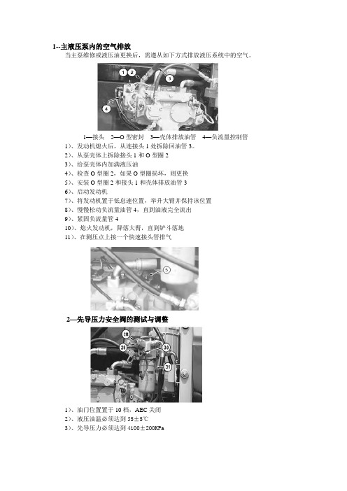
1--主液压泵内的空气排放当主泵维修或液压油更换后,需遵从如下方式排放液压系统中的空气。
1—接头2—O型密封3—壳体排放油管4—负流量控制管1)、发动机熄火后,从连接头1处拆除回油管3。
2)、从泵壳体上拆除接头1和O型圈23)、给泵壳体内加满液压油4)、检查O型圈2,如果O型圈损坏,则更换5)、安装O型圈2和接头1和壳体排放油管36)、启动发动机7)、将发动机置于低怠速位置,举升大臂并保持该位置8)、慢慢松动负流量油管4,直到油液完全流出9)、紧固负流量管410)、熄火发动机,降落大臂,直到铲斗落地11)、在测压点上接一个快速接头管排气2—先导压力安全阀的测试与调整1)、油门位置置于10档,AEC关闭2)、液压油温必须达到55±5℃3)、先导压力必须达到4100±200KPa2--主安全阀的测试与调整1/2—左右泵压力测试点 3—Ps压力测试点1)、油门置于10档,AEC开关取消2)、液压油温度必须达到55±5℃3)、憋铲斗液压缸4)、主安全阀压力必须达到35000±500KPa4—调整螺丝 5—锁紧螺母 6—主安全阀3—管道安全阀的测试与调整7、大臂油缸杆端管道压力阀8、铲斗油缸杆端管道压力阀9、小臂油缸杆端管道压力阀1)、发动机油门置于10档,AEC设定为OFF状态2)、液压油温必须达到55±5℃3)、Ps压力必须固定在2850 KPa(415 Psi)10—大臂防漂阀11—大臂缸杆端管道压力阀12—小臂液压缸杆端压力阀13—小臂防漂阀大臂、小臂大腔压力应该为38000KP a±1000KPa大臂、小臂杆腔压力应该为37000KPa±1000KPa铲斗缸大腔、杆腔压力应该为37000KPa±1000Kpa4---行走压力测试与调整油门10档,AEC开关取消,液压油温55±5℃,Ps固定在2850KPa 行走马达憋住测试压力:37500Kpa±1500Kpa5—主泵恒功率流量的测试与控制8、左泵测压点11、左泵高压管12、右动泵高压管16、右动泵测压点23、右泵24、左泵50、Ps压力测压点停机,释放挖掘机液压系统压力,从右泵上拆除油管12,1-1-回转马达2-回转马达连接器3-6V9840回转T型接头4-回转马达补充管6-右泵负流量控制管10-4C9910便携式流量测试计11-左泵油管12-右泵油管13-左泵负流量控制管23-右泵24-左泵29-1U8303装置30-5K9090 O型圈31-5P0201油管32-5P1010套子33-4C8767耦合器34-7M8485 O型圈35-4C6481连接器总成36-4C6482奶嘴总成37-4I6141连接器38-8C9026适配器39-6K6307 O型圈40-6V9854弯头二通阀42-1P3703矩形密封46-8T4184螺栓47-8T4223弹簧垫48-6V0400半圆法兰49-1U8292适配器1-回转马达2-接头3-T型三通阀4-补油管5-主控阀8-左泵压力测试点9-8T0861压力表10-4C9910便携式流量计11-左泵高压管12-右泵高压管16-主泵压力测试点20-8T0856压力表21-发动机22-多功能仪23-右泵24-左泵40-弯头二通阀50-Ps压力测试点1、回转马达2、连接器3、T型三通阀4、补偿油管40、弯头二通阀5--挖掘机速度测试行走测试A---先走的5米B---需要走20米C---离地高度0.5---1m AEC开关取消,油门10档,油温55±5℃新机器高速 14秒,维修极限 16秒低速 22秒,维修极限 25秒新机器高速 17秒,维修极限 19秒低速 27.5秒,维修极限 30.5秒回转的测试AEC开关取消,油门10档,油温55℃±5℃新机回转180度 4.2秒,维修极限 5.2秒偏摆距离1100mm, 极限1400mm大臂防漂移测试铲斗负载1吨,加长的底盘负载1.2吨小臂油缸伸出70mm,,机器保持该位置3分钟,大臂液压缸缩回6mm,小臂油缸伸出12mm,铲斗油缸缩回18mm空斗防漂测试铲斗液压缸完全伸出,小臂液压缸只能伸出70mm,举升大臂,直到大臂销与铲斗销在同一水平位置。
卡特挖掘机CAT320D 320DL 样本中文

320D/320D L®液压挖掘机依靠卡特彼勒和其广泛的代理商网络,我们可为您每天面对的问题提供✔新特性3底座设计和履带支重轮架。
X形、箱型截面的底座结构具有极佳的抗扭转弯曲的能力。
机器人焊接的履带支重底盘系统。
耐用的卡特彼勒底盘系统可吸收应力并具有极佳的稳定性。
标准底盘系统。
标准底盘系统非常适用于那些需要频繁改变机器位置、工作空间受限制、地面不平或多石的监控器。
监控器是 400x234 像素彩色液晶 (LCD)图形显示器。
监控器角度可以调整,以便尽可能避免阳光照控制台。
经过重新设计的控制台采用了简单而功能性的设计,可以减轻操动臂、斗杆和附件。
320D可提供范围广泛的适用于各种应用类型的配重型标准动臂。
标准动臂可配备两种斗杆,采用了优化设计,从而尽可能作业机具控制系统。
通过设置液压油流量、压力和操作员操纵装置以与特定作业机具相匹配,选装的作业机振动板压实机。
卡特彼勒振动板压实机采用一组可靠和低保养的组件,可以产生出众的压实力。
这些机器可以站在地面上便可进行维修。
320D的设计和布局考虑到需要为维修技工提供方便。
许多保养位置站在地面上就可很容易地够到,从而能够快捷高效地进行重要的保养。
空气滤清器室。
空气滤清器有双滤芯结构,使滤清效率更高。
当空气滤清器堵塞时,驾驶室内的监控器屏幕上会显示警告信息。
油泵室。
通过上部结构右侧的检修门能够站在地面上维修油泵和先导滤清器。
产品支持。
卡特彼勒代理商的零件柜台有几乎全部的零件。
卡特彼勒代理商利用国际计算机网络查询零件库存,把机器停工时间减到最小。
还可选用再制造部件以节约成本。
机器选择。
购买之前请仔细比较您想购买。
仔细研究最初的价格。
并考虑可利用的资金来源以及每日的运行费用。
此时也要注意可以包含在机器成本内的代理商服务质量,以便从长远角度来节约设备的运营成本。
客户支持协议。
卡特彼勒代理商提供操作。
改进操作技术可以提高您的效益。
您的卡特彼勒代理商拥有录像带、手册和其他知识,可以帮助您提高生产率,而且卡特彼勒会提供操作员认证培训课程,以帮助使您的投资收益率达到最大化。
CAT 320型电脑资料
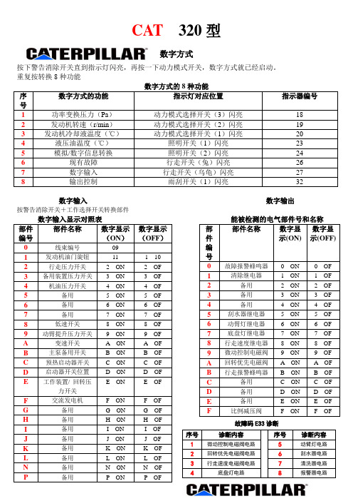
按下警告消除开关直到指示灯闪亮,再按一下动力模式开关,数字方式就已经启动。
重复按转换8种功能按警告消除开关+工作选择开关转换部件故障码E33诊断锁钥开关在关的位置,按下维修服务开关打开锁钥开关,到显示(20H)放开维修服务开关就已经进入校核方式调速器故障码比例减压阀校核在更换或修理比例减压阀或控制器后,必须进行校核。
校核时,在功率变换压力为0.5MPa和2.5MPa 时进行,液压油温度要达到50℃。
(1)使发动机熄火,在功率变换压力测试点处装一个6MPa的压力表。
(2)确认主泵备用开关在AUTO位置。
(3)启动校核方式。
(4)发动机油门旋钮应位于位置10,否则数字显示屏的第一个位置将显示“E”。
(5)按下行走速度变换开关,直到行走低速指示器(“乌龟”)闪亮。
(6)此时,数字显示屏显示“10”,其中“1”表示第一校核点已得到,“0”表示19个校核步骤的中间步骤已得到。
每一个步骤将使功率变换压力变化50KPa。
(7)调整功率变换压力:按下AEC开关一次,数字显示屏上的显示将变成[11]。
每按下一次AEC开关,数字显示上的显示将增加1,压力表上的读数将增加50KPa,直到数字显示屏显示[19]为止。
按下清洗器开关一次,数字显示屏上的显示将变成[-1]。
每按下一次清洗器开关,数字显示屏上的显示将减少1,压力表上的读数将降低50KPa,直到数字显示屏显示[-9]为止。
(8)要想建立第一校核点,可按下清洗器开关或AEC开关,直到压力表上的读数达到0.5MPa为止,调整压力时,总是向压力增加的方向进行。
按下警告消除开关,把数据储存在控制器中。
与此同时,数字显示屏会显示[20],表明第一校核点已经确认,可以继续建立第二校核点。
(9)要想建立第二校核点,可按下清洗器开关或AEC开关,直到压力表上的读数达到2.5MPa为止。
调整压力时,总是向压力增加的方向进行。
按下警告消除开关,把数据储存在控制器中。
与此同时,数字显示屏会显示[10],表明第二校核点已经确认,控制器已复位到第一校核点。
Cat 320 GC 超级流水线挖掘机高性能与低耗能说明书

Cat® 320 GCHydraulic ExcavatorHigh Performance with Lower Fuel Consumption•The excavator uses up to 20 percent less fuel than the 320F insimilar applications.•Match the excavator to the job with power modes; let Smartmode automatically match engine and hydraulic power to diggingconditions.•The advanced hydraulic system provides the optimum balanceof power and effi ciency while giving you the control you needfor precise digging requirements.• Valve priority puts hydraulic pressure and fl ow where you commandit to go for fast light- to medium-load cycle times.•The engine meets U.S. EPA Tier 4 Final and EU Stage IV emissionstandards with an aftertreatment system that requires no operatorinput or downtime.•Add auxiliary hydraulics to do more work with a range ofCat attachments.•Product Link™ comes standard so you can remotely monitormachine health, location, hours, and fuel consumption on demandthrough the VisionLink® online interface.Reliable, High and Low, Heat and Cold• Work up to 3000 m (9,840 ft) above sea level without de-rating.•Standard high-ambient temperature capability is 52º C (125º F)with cold start capability at –32º C (–25º F).•Auto warm up speeds up hydraulic oil warming in cold temperaturesand helps prolong the life of components.• Three levels of fuel fi ltration protect the engine from dirty diesel fuel.• Grease sealed between track pins and bushings reduces travel noiseand prevents debris from entering to increase undercarriage life.•The center track guiding guard helps keep the excavator trackaligned when traveling and working on slopes.• The sloped track frame prevents mud and debris accumulation,helping reduce risk of track damage.Work in Comfort in the All-New Cab•The Comfort cab has a wide seat that adjusts for operators ofall sizes.•Control the excavator comfortably with easy-to-reach controlsall located in front of you.•Standard automatic climate control keeps you at the righttemperature all shift long.•Advanced viscous mounts reduce cab vibration by up to 50 percentover previous excavator models.•Stow your gear with plenty of in-cab storage beneath and behindthe seat, overhead, and in the consoles. A cup holder, documentholder, bottle holder, and coat hook are also provided.•Use the standard radio’s USB ports and Bluetooth® technologyto connect to personal devices.Simple to Operate•Start the engine with a push button; use a Bluetooth key fob,smartphone app, or the unique Operator ID function.•Program each joystick button, including response and pattern,using Operator ID; it will also remember climate control fanand radio settings.•Navigate quickly on the standard high-resolution 203 mm (8 in)touchscreen monitor or with the aid of the jog dial control.•Not sure how a function works or how to maintain the excavator?Always have the operator’s manual at your fi ngertips in thetouchscreen monitor.The Cat® 320 GC excavator balances productivity with easy-to-use controls, a new comfortable cab, reduced fuel consumption by up to 20percent, and longer maintenance intervals that reduce maintenance costs up to 15 percent – all to give you a durable, low-cost-per-hour excavator to meet your light- to medium-duty application requirements.Not all features available in all regions. Consult your Cat dealer for specifi c confi gurations available in your region.Cat® 320 GC Hydraulic ExcavatorMaintenance•Expect up to 15 percent less maintenance cost than the 320E. (Savings calculated over 12,000 machine hours.)•Do all daily maintenance at ground level.•Check engine oil level quickly and safely with the new ground-level engine oil dipstick; fi ll and check engine oil on top of the machine with a conveniently located second dipstick.•Track your excavator’s fi lter life and maintenance intervals via the in-cab monitor.• Do no required maintenance on the Cat Clean Emissions Module.•Change all fuel fi lters at a synchronized 500 hours.•Expect the new air intake fi lter with precleaner to last up to1,000 hours – a 100 percent increase over the previous fi lter.• The new hydraulic oil fi lter provides improved fi ltration performance, anti-drain valves to keep oil clean when the fi lter is replaced, and longer life with a 3,000 hour replacement interval – 50 percent longer than previous fi lter designs.• The new high-effi ciency electric cooling fans only run when needed and reverse to keep cores free from debris.•S·O·S SM ports simplify maintenance and allow for quick, easy extraction of samples for fl uid analysis.Safety•Access 100 percent of daily maintenance points from ground level –no need for you to climb on top of the excavator.•Keep your excavator secure with Operator ID. Use your PIN code on the monitor to enable the pushbutton starting feature.•The standard ROPS cab meets ISO 12117-2:2008 requirements.•Enjoy great visibility into the trench, in each swing direction, and behind you with the help of smaller cab posts and larger windows.• A rearview camera is standard, and a right-side-view camerais optional.•The new right-hand service platform design provides easy, safe, and quick access to upper service platform; the service platform steps use anti-skid punch plate to prevent slipping.•The handrails comply with ISO 2867:2011 requirements.•The lower frame meets ISO 15818:2017 lifting and tie-down requirements.Cat® 320 GC Hydraulic Excavator Standard and Optional EquipmentStandard and optional equipment may vary. Consult your Cat dealer for details.Standard Optional CABROPS, standard sound suppression9High-resolution 203 mm (8 in)LCD touchscreen monitor9 Mechanically adjustable seat9CAT CONNECT TECHNOLOGYCat Product Link9ENGINETwo selectable power modes9One-touch low idle with auto enginespeed control9Auto engine idle shutdown952° C (125° F) high-ambient cooling capacity9–32° C (–25° F) cold start capability9Double element air fi lter withintegrated precleaner9Reversing electric cooling fans9Biodiesel capability up to B209 HYDRAULIC SYSTEMBoom and stick regeneration circuits9Boom and stick lowering check valves9 Auto hydraulic warm up9Auto two-speed travel9Boom and stick drift reduction valve9Hammer return fi lter circuit9 Slider joysticks9 Combined fl ow/high-pressureauxiliary circuit9 Medium-pressure circuit9 Quick coupler circuit for Cat Pin Grabber9Standard Optional BOOM AND STICKS5.7 m (18'8") reach boom, 2.9 m (9'6") stick9 UNDERCARRIAGE AND STRUCTURES600 mm (24") triple grouser shoes9 700 mm (28") triple grouser shoes9 790 mm (31") triple grouser shoes9 Tie-down points on base frame94200 kg (9,300 lb) counterweight9 ELECTRICAL SYSTEMTwo 1,000 CCA maintenance-free batteries9 Programmable time-delay LEDworking lights9LED chassis light, left-hand/right-handboom lights, cab lights9SERVICE AND MAINTENANCESampling ports for Scheduled Oil Sampling(S·O·S)9Ground- and platform-level engineoil dipsticks9SAFETY AND SECURITYRearview camera9Right-hand-side camera9*9* Right-hand mirror9Ground-level engine shutoff switch9Right-hand handrail and hand hold9Signaling/warning horn9*Europe standard; other regions optional.Cat® 320 GC Hydraulic ExcavatorEngine Model Cat C4.4 ACERT™Gross Power – ISO 14396/SAE J199591 kW122 hp Net Power – ISO 9249/SAE J134990 kW121 hp Engine RPMOperation1,700 rpmTravel2,000 rpmBore105 mm 4 in Stroke127 mm 5 in Displacement 4.4 L269 in3Main System – Maximum Flow (Implement)442 L/min116 gal/min Maximum Pressure – Equipment35 000 kPa5,075 psi Maximum Pressure – Travel34 300 kPa4,974 psi Maximum Pressure – Swing26 800 kPa3,886 psiOperating Weight21 900 kg48,300 lb • 5.7 m (18'8") reach boom, 2.9 m (9'6") reach stick, 1.0 m3 (1.31 yd3) HD bucket, 790 mm (31") shoes.Fuel Tank345 L86.6 gal Cooling System35 L9.2 gal Engine Oil15 L 4 gal Swing Drive (each)7 L 1.8 gal Final Drive (each) 6 L 1.6 gal Hydraulic System (including tank)240 L63.4 gal Hydraulic Tank128 L33.8 gal DEF Tank40 L10.6 gal Boom Reach 5.7 m (18'8") Stick Reach 2.9 m (9'6") Bucket 1.0 m3 (1.31 yd3) Shipping Height (top of cab)2960 mm9'9" Handrail Height2950 mm9'8" Shipping Length9530 mm31'3" Tail Swing Radius2830 mm9'3" Track Length to Center of Rollers3270 mm10'9" Ground Clearance470 mm1'7" Track Gauge2380 mm7'9" Transport Width – 790 mm (31") Shoes3170 mm10'5" Counterweight Clearance1050 mm3'5"Boom Reach 5.7 m (18'8") Stick Reach 2.9 m (9'6") Bucket 1.0 m3 (1.31 yd3) Maximum Digging Depth6720 mm22'1" Maximum Reach at Ground Level9860 mm32'4" Maximum Cutting Height9450 mm31'0" Maximum Loading Height6490 mm21'4" Minimum Loading Height2170 mm7'1" Maximum Depth Cut for 2440 mm (8'0")Level Bottom6550 mm21'6" Maximum Vertical Wall Digging Depth5690 mm18'8" Bucket Digging Force (ISO)129 kN29,000 lbf Stick Digging Force (ISO)99 kN22,256 lbf Bucket Digging Force (SAE)115 kN25,853 lbf Stick Digging Force (SAE)96 kN21,581 lbfTechnical SpecificationsFor more complete information on Cat products, dealer services, and industry solutions, visit us on the web at © 2017 CaterpillarAll rights reservedMaterials and specifi cations are subject to change without notice. Featured machines in photos may include additional equipment. See your Cat dealer for available options.CAT, CATERPILLAR, , their respective logos, “Caterpillar Yellow” and the “Power Edge” trade dress, as well as corporate and product identity used herein, are trademarks of Caterpillar and may not be used without permission.AEXQ2191 (07-2017)Build Number: 07A (North America, Europe)。
卡特320D 320DL挖掘机产品说明

2
Structures
Caterpillar® design and manufacturing techniques assure outstanding durability and service life from these important components. pg. 8
Booms, Sticks and Bucket Linkages
Work Tools – Attachments
Three lengths of booms and five sticks are available, offering a range of configurations suitable for a wide variety of application conditions. The bucket linkage pins have been enlarged to improve reliability and durability. All Booms and Sticks are stress relieved. pg. 9
Cat C6.4. The Cat C6.4 with ACERT™ Technology introduces a series of evolutionary, incremental improvements that provide breakthrough engine technology. The building blocks of ACERT Technology are fuel delivery, air management and electronic control. ACERT Technology optimizes engine performance while meeting global low emission regulations. With its proven technology, robust components and precision manufacturing, you can count on this engine to power up at start time and keep working productively all shift long.
320MD功能码参数
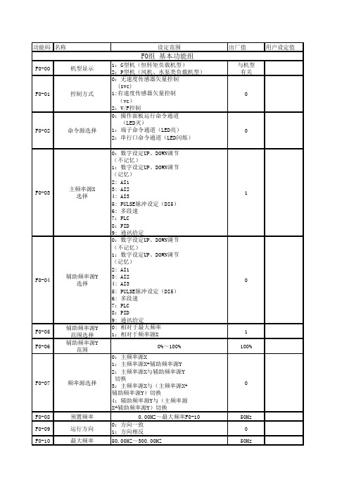
功能码名称设定范围出厂值用户设定值F0-00机型显示1:G型机(恒转矩负载机型)2:P型机(风机、水泵类负载机型)与机型有关F0-01控制方式0:无速度传感器矢量控制(svc)1:有速度传感器矢量控制(vc)2:V/F控制F0-02命令源选择0:操作面板运行命令通道(LED灭)1:端子命令通道(LED亮)2:串行口命令通道(LED闪烁)F0-03主频率源X选择0:数字设定UP、DOWN调节(不记忆)1:数字设定UP、DOWN调节(记忆)2: AI13: AI24: AI35: PULSE脉冲设定(DI5)6: 多段速7:PLC8:PID9: 通讯给定1F0-04辅助频率源Y选择0:数字设定UP、DOWN调节(不记忆)1:数字设定UP、DOWN调节(记忆)2: AI13: AI24: AI35: PULSE脉冲设定(DI5)6: 多段速7:PLC8:PID9: 通讯给定F0-05辅助频率源Y范围选择0: 相对于最大频率1:相对于频率源X1F0-06辅助频率源Y范围0%~100%100%F0-07频率源选择0:主频率源X1:主频率源X+辅助频率源Y2:主频率源X与辅助频率源Y切换3:主频率源X与(主频率源X+辅助频率源Y)切换4:辅助频率源Y与(主频率源X+辅助频率源Y)切换F0-08预置频率0.00HZ~最大频率F0-1050HzF0-09运行方向0:方向一致1:方向相反F0-10最大频率50.00HZ~300.00HZ50HzF0组 基本功能组F0-11上限频率源0:F0-12设定1:AI12:AI23:AI34:PULSE设定5:通讯给定F0-12上限频率下限频率F0-14~最大频率源F0-1050Hz F0-13上限频率偏置0.00HZ~最大频率F0-100.00Hz F0-14下限频率0.00HZ~上限频率F0-120.00Hz F0-15载波频率0.5kHZ~16.0kHZ与机型 有关F0-16载波频率调整选择0:固定PWM,载频温度调整无效1:随机PWM,载频温度调整无效2:固定PWM,载波温度调整无效3:随机PWM,载波温度调整有效2F0-17加速时间10.0s~6500.0s 20s F0-18减速时间10.0s~6500.0s20sF1-00电机类型选择0:普通异步电机1:变频异步电机2:永磁同步电机0F1-01额定功率0.4kW~1000.0kW 机型确定F1-02额定电压0V~440V 380V F1-03额定电流0.01A~655.35A 机型确定F1-04额定频率0.00~最大频率50.00Hz F1-05额定转速0rpm~30000rpm 1460rpm F1-06定子电阻0.001Ω~65.535Ω机型确定F1-07转子电阻0.001Ω~65.535Ω机型确定F1-08漏感抗0.01mH~655.35mH 机型确定F1-09互感抗0.1mH~6553.5mH 机型确定F1-10空载电流0.01A~650.00A 机型确定F1-11调谐选择0:无操作1:静止调谐2:完整调谐F2-00速度环比例增益10~10030F2-01速度环积分时间10.01s~10.00s 0.50s F2-02切换频率0.00~F2-05 5.00Hz F2-03速度环比例增益20~10020F2-04速度环积分时间20.01s~10.00s 1.00s F2-05切换频率2F2-02~最大频率10.00Hz F2-06转差补偿系数50%~200%100%F2组 矢量控制参数F1组 电机参数F2-07速度环滤波时间常数0.000s~0.100s0.0000sF2-08转矩控制0:无效 1:有效0F2-09转矩上限源0:F2-101:AI12:AI23:AI34:PULSE设定5:通信给定模拟输入量程对应F2-10F2-10转矩上限0.0%~200.0% 1.5 F2-11编码器脉冲数1~655351024 F2-12预留0~655350F3-00V/F曲线设定0:直线V/F曲线1:多点V/F曲线2:平方V/F曲线F3-01转矩提升0.0:(自动)0.1%~30.0% 1.00%F3-02转矩提升截止频率0.00HZ~最大频率50.00HzF3-03V/F频率点10.00HZ~电机额定频率0.00Hz F3-04V/F电压点10.0%~100.0%0.00% F3-05V/F频率点20.00HZ~电机额定频率0.00Hz F3-06V/F电压点20.0%~100.0%0.00% F3-07V/F频率点30.00HZ~电机额定频率0.00Hz F3-08V/F电压点30.0%~100.0%0.00% F3-09转差补偿系数0.0%~200.0%0.00%F3-10AVR选择0:无效1:全程有效2:仅在减速时无效2F3-11振荡抑制增益0~100机型确定F4-00DI1端子功能选择1F4-01DI2端子功能选择4F4-02DI3端子功能选择9F4-03DI4端子功能选择12F4-04DI5端子功能选择13F4-05DI6端子功能选择(在IO扩展卡上)F4-06DI7端子功能选择(在IO扩展卡上)0:无功能1:正转运行(FWD)2:反转运行(REV)3:三线式运行控制4:正转点动(FJOG)5:反转点动(RJOG)6:端子UP7:端子DOWN8:自由停车9:故障复位(RESET)10:运行暂停11:外部故障常开输入12:多段速端子113:多段速端子214:多段速端子315:多段速端子416:加减速选择端子117:加减速选择端子2F3 V/F控制参数F4 输入端子F4-07DI8端子功能选择(在IO扩展卡上)F4-08DI9端子功能选择(在IO扩展卡上)F4-09DI10端子功能选择(在IO扩展卡上)20:运行命令切换端子21:加减速禁止22:PID暂停23:PLC状态复位24:摆频停止25:记数器输入26:计数器复位27:长度记数输入28:长度复位29:转矩控制禁止30:PULSE(脉冲)频率输入(仅对DI5有效)31:保留32:直流制动命令33:外部故障常闭输入34:频率设定起效端子(此端子功能不设,默认为有效)若设定该端子功能,则当频率修改时,通过此端子有效来控制修改起效时刻35:PID作用方向取反端子该端子有效,则PID作用方向与FA-03设定的方向相反36:外部停车端子键盘控制时,可用该端子停车,相当于键盘上的STOP键37:控制命令切换端子2用于在端子控制和通讯控制之间切换,该端子有效,若F0-02设为端子控制,则切换到通讯控制:若F0-02设为通讯控制,则切换到端子控制38:PID积分暂停端子该端子有效,PID积分作用暂停,但比例调节和微分调节依然起作用F4-10DI端子滤波时间1~104F4-11端子命令方式0:两线式11:两线式22:三线式13:三线式2F4-12端子UP/DOWN变化率0.01Hz/s~100.00Hz/s 1.00Hz/s F4-13AI1最小输入0.00V~10.00V待确认F4-14AI1最小输入对应设定负100%~100%0.00%F4-15AI1最大输入0.00V~10.00V10.00VF4-16AI1最大输入对应设定负100%~100%100.00% 4:正转点动(FJOG)5:反转点动(RJOG)6:端子UP7:端子DOWN8:自由停车9:故障复位(RESET)10:运行暂停11:外部故障常开输入12:多段速端子113:多段速端子214:多段速端子315:多段速端子416:加减速选择端子117:加减速选择端子218:频率源切换19:UP/DOWN设定清零(端子、键盘)F4-17AI1输入滤波时间0.00s~10.00s0.10sF4-18AI2最小输入0.00V~10.00V0.00VF4-19AI2最小输入对应设定负100%~100%0.00%F4-20AI2最大输入0.00V~10.00V10.00VF4-21AI2最大输入对应设定负100%~100%100.00%F4-22AI2输入滤波时间0.00s~10.00s0.10sF4-23AI2最小输入(IO扩展卡上)0.00V~10.00V0.00VF4-24AI2最小输入对应设定(IO扩展卡上)负100%~100%0.00%F4-25AI2最大输入(IO扩展卡上)0.00V~10.00V10.00VF4-26AI2最大输入对应设定(IO扩展卡上)负100%~100%100.00%F4-27AI2输入滤波时间(IO扩展卡上)0.00s~10.00s0.10sF4-28PULSE(脉冲)输入最小频率0.00kHz~50.00kHz0.00KHzF4-29PULSE(脉冲)输入最小频率对应设定负100%~100%0.00%F4-30PULSE(脉冲)输入最大频率0.00kHz~50.00kHz50KHzF4-31PULSE(脉冲)输入最大频率对应设定负100%~100%100.00%F4-32PULSE(脉冲)输入滤波时间0.00s~10.00s0.01sF5-00FM端子输出方式选择0:脉冲输出(FMP)1:开路集电极开关量输出(FMR)F5-01FMR输出选择0F5-02控制板继电器(T/A-T/B-T/C)输出选择20:无输出1:变频器运行中2:故障输出3:频率水平检测FPD输出4:频率到达5:零速运行中6:电机过载预报警7:变频器过载预报警8:设定计数值到达9:指定计数值到达10:长度到达11:PLC循环完成12:运行时间到达13:频率限定中F5组 输入端子F5-03扩展卡继电器(P/A-P/B-P/C)输出选择F5-04DO1输出选择1F5-05扩展卡DO2输出选择4F5-06FMP输出选择0 F5-07AO1输出选择0F5-08扩展卡AO2输出选择1F5-09FMP输出最大频率0.1kHz~50.00kHz50.0KHzF5-10AO1零偏系数负100%~100%0.00% F5-11AO1增益负10~101F5-12AO2零偏系数(在IO扩展卡上)负100%~100%0.00%F5-13AO21增益(在IO扩展卡上)负10~101F6-00启动方式0:直接启动1:速度跟踪再启动F6-01速度跟踪方式0:从停机频率开始1:从零速开始2:从最大频率开始F6-02转速跟踪快慢1~10020 F6-03启动频率0.00Hz~10.00Hz0.00HzF6-04启动频率保持时间0.0s~36.0s 0.0s1:变频器运行中2:故障输出3:频率水平检测FPD输出4:频率到达5:零速运行中6:电机过载预报警7:变频器过载预报警8:设定计数值到达9:指定计数值到达10:长度到达11:PLC循环完成12:运行时间到达13:频率限定中14:转矩限定中15:运行准备就绪16:AI1>AI217:保留18:上限频率到达19:下限频率到达20:通讯给定0:运行频率1:设定频率2:输出电流3:输出转矩4:输出功率5:输出电压6:PULSE输入7:AI18:AI29:AI3(扩展卡)10:长度11:记数值12:通讯给定13:保留14:保留15:保留16:待确定F6组 启停控制F6-05启动直流制动电流0%~100%0%F6-06启动直流制动时间0.0s~36.0s 0.0s F6-07加减速方式0:直线加减速1:S曲线加减速0F6-08S曲线开始段时间0.0%~40.0%30.00%F6-09S曲线结束段时间0.0%~40.0%30.00%F6-10停机方式0:减速停车1:自由停车0F6-11停机直流制动开始频率0.00Hz~最大频率0.00Hz F6-12停机直流制动等待频率0.0s~36.0s0.0s F6-13停机直流制动电流0%~100%0.00%F6-14停机直流制动时间0.0s~36.0s 0.0s F6-15制动使用率0%~100%100%F7-00LCD语言选择0:汉语1:英语F7-01MF.K键功能选择0:MF.K无效1:操作面板命令通道与远程命令通道(端子命令通道或串行口通讯命令通道)切换2:正反转切换3:正转点动F7-02STOP/RESET功能键0:只在键盘控制时有效1:端子控制时,STOP键停机功能有效2:端子控制时,STOP键故障复位功能有效3:端子控制时,STOP键停机功能和故障复位功能都有效F7-03QUICK参数锁定0:QUICK参数锁定无效1:QUICK参数锁定有效0F7-04LED运行显示参数0~655350F7-05LED停机显示参数1~65535255F7-06负载速度显示系数0.0001~6.50001F7-07散热器温度10.0℃~100℃F7-08散热器温度20.0℃~100℃F7-09软件版本号1F7-10软件版本号2F8-00点动运行频率0.00Hz~最大频率 2.00HZ F8-01点动加速时间0.0s~6500.0s 20.0s F8-02点动减速时间0.0s~6500.0s 20.0s F8-03加速时间20.0s~6500.0s 20.0s F8-04减速时间20.0s~6500.0s20.0sF7组 键盘与显示F8组 辅助功能F8-05加速时间30.0s~6500.0s20.0s F8-06减速时间30.0s~6500.0s20.0s F8-07加速时间40.0s~6500.0s20.0s F8-08减速时间40.0s~6500.0s20.0s F8-09跳跃频率10.00Hz~最大频率0.00Hz F8-10跳跃频率10.00Hz~最大频率0.00Hz F8-11跳跃频率幅度0.00Hz~最大频率0.01Hz F8-12正反转死区时间0.0s~3000.0s0.0sF8-13反转控制0:允许反转1:禁止反转0F8-14设定频率低于下限频率动作0:以下限频率运行1:停机2:零速运行F8-15下垂控制0.00Hz~10.00Hz0.00HzF8-16过调制使用0:过调制无效1:过调制有效1F8-17设定运行时间0h~65535h65535hF8-18启动保护选择0:不保护1:保护F8-19频率检测值(FDT电平)0.00Hz~最大频率50.00HzF8-20频率检测滞后值(FDT滞后)0.0%~100.0%(FDT电平)5%F8-21频率到达检出宽度0.0%~100.0%(最大频率)0.00%F8-22上电对地短路保护检测0:无效1:有效1F8-23运行时间到动作选择0:继续运行1:停机F9-00电机过载保护选择0:禁止1:允许1F9-01电机过载保护增益0.20~10.001 F9-02电机过载预警系数50%~100%80% F9-03过压失速增益0(无过压失速)~1000 F9-04过电压失速保护电压120%~150%130% F9-05过流失速增益0~10020 F9-06过电流失速保护电流100%~200%150%F9-07瞬停不停功能0:禁止1:允许F9-08瞬停不停频率下降率0.00Hz/s~最大频率/s10.00Hz/s F9-09故障自动复位次数0~30F9-10故障自动复位期间故障继电器动作选择(T/A-T/B-T/C)0:不动作1:动作F9-11故障自动复位间隔时间0.1s~100.0s 1.0sF9-12输入缺相保护选择0:禁止1:允许1 F9组 故障与保护F9-13输出缺相保护选择0:禁止1:允许1FA-00PID给定源0:FA-011:AI12:AI23:AI34:PULSE设定(DI5)5:通讯给定FA-01PID键盘给定0.0%~100.0%50%FA-02PID反馈源0:AI11:AI22:AI33:AI1-AI24:PULSE设定(DI5)5:通讯给定FA-03PID作用方向0:正作用1:反作用FA-04PID给定源量程0~655351000 FA-05比例增益P0.0~100.020 FA-06积分时间I0.01s~10.00s2 FA-07微分时间D0.0s~100.0s0 FA-08PID反转截止频率0.00Hz~最大频率 2.00HZ FA-09偏差极限0.0%~100.0%0.00% FA-10微分限幅0.0%~100.0%5%FP-00用户密码0~655350FP-01参数初始化0:无操作1:恢复出厂设定值2:清除故障记录FA组 PID功能FP组 用户密码。
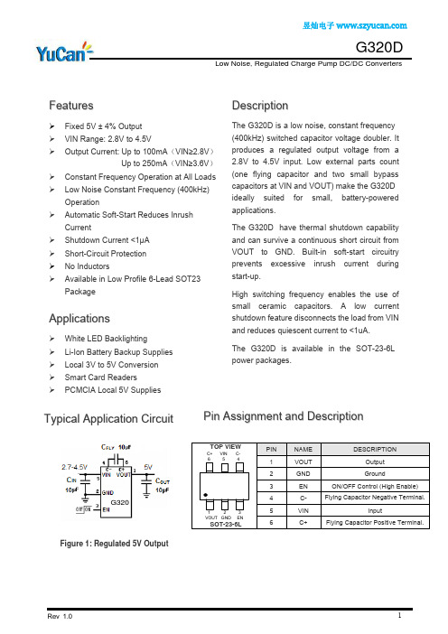
G320D
Block Diagram
Application Information
Oscillator Frequency vs.Supply Voltage ( ILOAD=100mA)
Supply CuVoltage (V)
3.3 3.7 4.1 Supply Voltage (V)
4.5
Short Circuit Current vs. Supply Voltage 350 300 Short Circuit Current (mA) 250 200 150 100 50 0 2.5 2.9 Supply Voltage (V) 3.3 3.7 4.1 4.5
Output Voltage vs. Supply Voltage ( ILOAD=0mA) 5.5 5.4 5.3 Output Voltage (V) 5.2 5.1 5 4.9 4.8 4.7 4.6 4.5 2.5 2.9 3.3 3.7 4.1 4.5 Supply Voltage (V)
* EFFI = [(Output Voltage × Output Current) / (Input Voltage × Input Current)] × 100%
Rev 1.0
2
昱灿电子
G320D
Low Noise, Regulated Charge Pump DC/DC Converters
Applications
White LED Backlighting Li-Ion Battery Backup Supplies Local 3V to 5V Conversion Smart Card Readers PCMCIA Local 5V Supplies
挖掘机各品牌情况比较

小松(常州)工程机械有限公司位于江苏省常州市,生产销售小松WA系列装载机、 27-40吨级挖掘机、非公路用货运自卸车等工程机械整机及零部件
小松(常州)铸造有限公司位于江苏省常州市,主要生产铸造部件
103
整机重量 5480
一般售价(参考)
7210
21500
324D/324D L
1.1-1.5
Cat (卡特)
C7 ACERT™
124
24790
325D/325D L
1.3-1.6
Cat (卡特)
C7 ACERT™
140
29240
330D/330D L
1.6-2.0
Cat (卡特)
C9 ACERT
200
SAA6D102E-2 SAA6D102E-2 SAA6D107E-1 SAA6D102E-2 SAA6D102E-2 SAA6D107E-1 SAA6D102E-2 SAA6D102E-2 SAA6D107E-1 SAA6D102E-2 SAA6D114E SAA6D114E SAA6D102E-2
输出功率KW
整机重量
一般售价(参考)
22
3915
29
5480
40
6300
66
12600
107
19700
107
21100
110
19900
107
19800
107
21200
110
20000
125
22900
125
24200
挖掘机配件

1 小松Komatsu (十大挖掘机品牌,小松(中国)投资有限公司)
2 日立 (挖掘机十大品牌,日本品牌,立建机(上海)有限公司)
3 现代ROBEX (韩国现代集团与常林股份合资现代江苏工程机械)
4 卡特cat (美国Caterpillar卡特彼勒重工集团公司)
5 斗山Doosan (十大挖掘机品牌,斗山工程机械(中国)有限公司)
松土器包括挖掘机用松土器和推土机用松土器,挖掘机松土器也叫斗钩,推土机用松土器也叫尾钩,一般是单齿,也有二齿或三齿,挖掘切入力强。适用于硬土、次坚石、风化石的粉碎、分裂,以便于用挖斗进行挖掘及装载作业。
挖掘机快速连接器 挖掘机快速连接器(也叫快换接头、快速连接头),快速连接器能在挖掘机上迅速安装各种配置件(挖斗、破碎锤、液压剪等),能扩大挖掘机使用范围,并能节省时间,提高工效。
铲斗按功能还分为水沟斗、栅格斗、清洁斗、倾斜斗等。水沟斗适用于各种形状壕沟的开挖,壕沟开挖一次成形,一般无需修整,作业效率高。栅格斗适用于分离较松散物料的挖掘,挖掘与分离一次完成,广泛用于市政、农业、林业、水利、土石方工程。清洁斗及倾斜斗适用于斜坡等平面的修整及河道、水沟的大容量清淤、清洁工作,其中倾斜斗能通过油缸来改变清洁斗的倾斜角度,大大提高工作效率。
适用挖掘机品牌:卡特CAT、小松PC、日立EX(ZAX)、神钢SK、大宇(斗山)DH、现代R、加藤HD、凯斯CX、住友SH、沃尔沃EC、柳工、玉柴、三一、徐挖、邦立等挖掘机系列。 铲斗 铲斗 这里是指安装在挖掘机上使用的铲斗,按工作方式分为反铲式和正铲式,一般常用的是反铲式。
铲斗按材质分为标准斗、加强斗、岩石斗、碎石斗等。标准斗材料选用国产优质高强度结构钢16Mn,适用于一般黏土、松土的挖掘和沙、土、砾石的装载等较轻作业环境。加强斗的易损部位齿座板和侧刃板材料选用国产优质高强度耐磨钢NM360,适用于挖掘混有较软碎石的硬土或碎石、砾石的装载等重载作业。岩石斗的齿座板和侧刃板材料选用瑞典进口的超高强度耐磨钢HARDOX,适用于挖掘混有较硬碎石的硬土、次坚石、风化石或坚石、爆破后的矿石的装载等重载作业环境。
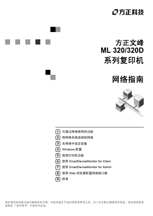
方正文峰 ML 320 320D 系列复印机 网络指南
• RSA Data Security, Inc. MD5 Message-Digest Algorithm © 1991-2, RSA Data Security, Inc. 1991。版权所有。 仅当在提及或参考本软件或本功能的任何资料中都注明 “RSA Data Security, Inc. MD5 MessageDigest Algorithm”时,才授权复制和使用本软件。 仅当在提及或参考本软件衍生产品的任何资料中都注明 “RSA Data Security, Inc. MD5 MessageDigest Algorithm”时,才授权开发和使用本软件的衍生产品。 RSA Data Security, Inc. 对于本软件的商业性或相对特定目的的适用性,未作任何明确表述。本软件 “按实物原样”供货,不带任何明确或隐含的保证。 在本资料或软件的任何副本中,都必须保留这些声明。
2. 将网络电缆连接到网络
确认连接 ...................................................................................................... 9 连接到 Ethernet 接口 ............................................................................................ 10
功能或者相关功能, ML 320/320D 系列复印机不支持。 方正文峰 ML 320/320D 系列复印机不提供 IEEE 1394 接口板、IEE E 802.11b 无线 LAN 板、Bluetooth 单元、PostScript3 单元等选件。 方正文峰 ML 320/320D 系列复印机不支持 Macintosh 打印。
cat320d参数

cat320d参数
1. 发动机类型:柴油发动机
2. 排量:2.0升
3. 最大马力:190马力
4. 最大扭矩:400牛·米
5. 变速器类型:手自一体变速器(8挡)
6. 发动机缸数:4缸
7. 助力系统:电动助力转向
8. 悬挂系统:前麦弗逊式独立悬挂,后多连杆式独立悬挂
9. 刹车系统:前盘式刹车,后盘式刹车
10. 安全系统:防抱死制动系统、电子稳定控制系统、轮胎压力监测系统、倒车雷达等
11. 车身尺寸:长4570毫米,宽1811毫米,高1421毫米
12. 燃油消耗:市区8.4升/百公里,市郊5.1升/百公里
13. 空载重量:1635千克
14. 前轮胎规格:225/50 R17
15. 后轮胎规格:225/50 R17
16. 燃油箱容量:57升
17. 最大加速时间:0-100公里/小时加速时间为7.5秒
18. 最高速度:228公里/小时
19. 座位数:5座
20. 车门数:4门。
(47)卡特320D英文测试与调整
RENR9848-0201/08/2006 320D, 323D, 324D, 325D, 328D and 330D Excavators and 325D MHPU and 330D MHPU Mobile Hydraulic Power Units Machine Electronic Control SystemJGZ1-UP (Machine)MDE1-UP (Machine)DBH1-UP (Machine)KBE1-UP (Machine)EAH1-UP (Machine)FFK1-UP (Machine)…Page 1 of 3z General Information - 320D, 323D 01/08/2006z General Information - 322D, 324D, 325D, 328D, 330D 01/08/2006z System Operation - 320D, 323D 01/08/2006{Engine Speed Control{Self-Diagnostic Function{Automatic Engine Control (AEC)First Setting Of The AECSecond Setting Of The AEC{One Touch Low IdleStart-up Of The One Touch Low IdleRelease Of The One Touch Low Idle{Engine Speed ProtectionPrevention of Overspeed During Low Engine Oil PressurePrevention Of Overspeed During Overheating ConditionControl Of The Hydraulic Oil At Low Temperatures{Pump RegulationConstant Horsepower ControlUnderspeed Control{Cooling Fan Control{Travel Speed - Hydraulic Circuit Change ControlAutomatic Travel Speed Change{Swing Brake Operation{Heavy Lift Mode (Optional){Tool ControlSelection Of A ToolEngine Speed ControlMain Pump Flow ControlMain Pump Control During Use Of The Auxiliary Pump{Backup SystemPump Torque ControlRelease Function of Swing Brake{Monitoring Systemz System Operation - 322D, 324D, 325D, 328D, 330D 01/08/2006{Engine Speed Control{Self-Diagnostic Function{Automatic Engine Control (AEC)First Setting Of The AECSecond Setting Of The AEC{One Touch Low IdleStart-up Of The One Touch Low IdleRelease Of The One Touch Low Idle{Engine Speed ProtectionPrevention of Overspeed During Low Engine Oil PressurePrevention Of Overspeed During Overheating ConditionControl Of The Hydraulic Oil At Low Temperatures{Pump RegulationConstant Control of HorsepowerControl Of An Underspeed Condition{Cooling Fan Control{Travel Speed - Hydraulic Circuit Change ControlAutomatic Travel Speed Change{Swing Brake Operation{Heavy Lift Mode (Optional) {Tool ControlSelection Of A ToolEngine Speed ControlMain Pump Flow ControlMain Pump Control During Use Of The Auxiliary Pump{Backup SystemPump Torque ControlRelease Function of Swing Brake{Monitoring Systemz Diagnostic Operation 01/08/2006{Troubleshooting Procedures{Module Identifier (MID){Failure Mode IdentifierDetailed FMI ExplanationEvent CodesData Status CodesCalibration Error ID Listz Electronic Control Module (Machine) 01/08/2006{Connector Contact Numbers{Machine ECMz Switches 01/08/2006{Engine Speed Dial Switch{Right Console Switch Panel{{Pressure SwitchTravel Pressure Switch, Implement Pressure Switch, Medium Pressure Switch, Joystick PressureSwitch, and Attachment Pedal Pressure Switch (Hammer){Key Start Switch{Toggle Switchz Sensors 01/08/2006{Engine Speed Sensor{Pressure SensorPump Discharge 1 (Drive) and Pump Discharge 2 (Idle)z Solenoids 01/08/2006{Pump Pressure Solenoid{Solenoid (ON/OFF)Travel Speed Change Solenoid Swing Brake SolenoidHydraulic Lock Solenoid{Flow Limit Solenoid{1P-2P Exchange 1 Solenoid{1P-2P Exchange 2 Solenoid, Heavy Lift Solenoidz Related Components 01/08/2006{Data LinksCat Data LinkCAN Data LinkOne Touch Low Idle SwitchPage 2 of 3Page 3 of 3{Action Alarm{Travel AlarmSystems Operation320D, 323D, 324D, 325D, 328D and 330D Excavators and 325D MHPU and 330D MHPU Mobile Hydraulic Power Units Machine Electronic Control SystemMedia Number -RENR9848-02 Publication Date -01/08/2006 Date Updated -31/08/2006i02508783 General Information - 320D, 323DSMCS - 5050-EK ; 7000S/N - CXY1-UPS/N - CYD1-UPS/N - CYW1-UPS/N - DHK1-UPS/N - DKW1-UPS/N - EBY1-UPS/N - EDX1-UPS/N - ERN1-UPS/N - FXK1-UPS/N - GBC1-UPS/N - GBR1-UPS/N - GKL1-UPS/N - HAS1-UPS/N - JGZ1-UPS/N - LWR1-UPS/N - MDE1-UPS/N - PBM1-UPS/N - PEL1-UPS/N - SDC1-UPS/N - THJ1-UPView ImageIllustration 1g 320D, 323D Machine ECM Block Diagram(1) Switch Panel(2) Air Cleaner Plugged Switch(3) Hydraulic Oil Filter Plugged Switch(4) ATT Hydraulic Oil Filter Plugged Switch(5) Fuel Filter Plugged Switch(6) No.2 Fuel Filter Plugged Switch(7) Water Separator Level Switch(8) Overload Warning Switch(9) Fine Swing Switch(10) Quick Coupler Switch(11) Travel Alarm Relay(12) Machine ECM(13) Starter Switch(14) Engine Speed Dial(15) One Touch Low Idle Switch(16) Speed Sensor(17) No.1 Pump Pressure Sensor(18) No.2 Pump Pressure Sensor.(19) Implement Pressure Switch(20) Travel Right Pressure Switch(21) Travel Left Pressure Switch(22) Backup Switch(23) Swing Brake Release Solenoid(24) Travel Speed Change Solenoid.(25) Power Shift Pressure Proportional Reducing Valve(26) Straight Travel Solenoid(27) Viscous Clutch(28) Heavy Lift Solenoid(29) Straight Travel Pressure Switch(30) Ambient Temperature Sensor(31) Overload Warning Pressure Sensor(32) Monitor(33) Fuel Level Sensor(34) Hydraulic Oil Temperature Sensor(35) Alternator(36) Air Heater controller(37) Fault Alarm(38) Engine Oil Level Switch(39) Engine Coolant Level Switch(40) Hydraulic Oil Level Switch(42) User Shutdown Switch(43) Engine Coolant Temperature Sensor(44) Engine Oil Pressure Switch(70) Governor acuatorThe Machine Electronic Control System provides electronic control of the hydraulic system. The system includes the following components: various inputs (switches and sensors), an electronic control module and various outputs (solenoid valves). The Machine ECM also controls the following functions:z Engine Speedz Track travel motorsz Travel alarmz Swing Brakez Heavy Liftz Attachment Actuatorsz Pump power shift pressurez Hydraulic Flow LimitThe machine ECM receives signals from the various input devices that are shown on illustration 1. The ECM makes decisions that are based on this information. The ECM acts on these decisions by actuating proportional solenoids, ON/OFF solenoids, and relays.General Information - 322D, 324D, 325D, 328D, 330D SMCS - 5050-EK ; 7000S/N - A3R1-UPS/N - AZP1-UPS/N - B6H1-UPS/N - C3N1-UPS/N - C4H1-UPS/N - C5K1-UPS/N - C7K1-UPS/N - C8L1-UPS/N - C9M1-UPS/N - CJX1-UPS/N - CYW1-UPS/N - D3D1-UPS/N - DBH1-UPS/N - DFP1-UPS/N - E4K1-UPS/N - EAH1-UPS/N - EDX1-UPS/N - EJC1-UPS/N - ERN1-UPS/N - FFK1-UPS/N - GBC1-UPS/N - GBR1-UPS/N - GGE1-UPS/N - GPB1-UPS/N - GTN1-UPS/N - H3K1-UP S/N - HAS1-UP S/N - JJG1-UP S/N - JKR1-UP S/N - JLP1-UP S/N - JLS1-UP S/N - KBE1-UP S/N - KDG1-UP S/N - L2K1-UP S/N - LAB1-UP S/N - LEM1-UP S/N - LWR1-UP S/N - MCL1-UP S/N - MEY1-UP S/N - MKR1-UP S/N - MWP1-UP S/N - NBD1-UP S/N - PAL1-UP S/N - PEL1-UP S/N - PKE1-UP S/N - RAS1-UP S/N - RJK1-UP S/N - SCR1-UP S/N - SYM1-UP S/N - T2D1-UP S/N - T2S1-UP S/N - T2Y1-UP S/N - THJ1-UPView ImageIllustration 1g 322D, 324D, 325D, 328D, 330D Machine ECM Block Diagram(1) Switch Panel(2) Air Cleaner Plugged Switch(3) Hydraulic Oil Filter Plugged Switch(4) ATT Hydraulic Oil Filter Plugged Switch(5) Fuel Filter Plugged Switch(6) No.2 Fuel Filter Plugged Switch(7) Water Separator Level Switch(8) Overload Warning Switch(9) Fine Swing Switch(10) Quick Coupler Switch(11) Travel Alarm Relay(12) Machine ECM(13) Starter Switch(14) Engine Speed Dial(15) One Touch Low Idle Switch(16) Speed Sensor(17) No.1 Pump Pressure Sensor(18) No.2 Pump Pressure Sensor.(19) Implement Pressure Switch(20) Travel Right Pressure Switch(21) Travel Left Pressure Switch(22) Backup Switch(23) Swing Brake Release Solenoid(24) Travel Speed Change Solenoid.(25) Power Shift Pressure Proportional Reducing Valve(26) Straight Travel Solenoid(27) Viscous Clutch(28) Heavy Lift Solenoid(29) Straight Travel Pressure Switch(30) Ambient Temperature Sensor(31) Overload Warning Pressure Sensor(32) Monitor(33) Fuel Level Sensor(34) Hydraulic Oil Temperature Sensor(35) Alternator(36) Air Heater controller(37) Fault Alarm(38) Engine Oil Level Switch(39) Engine Coolant Level Switch(40) Hydraulic Oil Level Switch(41) Engine ECM(42) User Shutdown Switch(43) Engine Coolant Temperature Sensor(44) Engine Oil Pressure SwitchThe Machine Electronic Control System provides electronic control of the hydraulic system. The system includes the following components: various inputs (switches and sensors), an electronic control module and various outputs (solenoid valves). The Engine Electronic Control Module (ECM) controls the engine. The Machine ECM also controls the following functions:z Engine Speedz Track travel motorsz Travel alarmz Swing Brakez Heavy Liftz Attachment Actuatorsz Pump power shift pressurez Hydraulic Flow LimitThe machine ECM receives signals from the various input devices that are shown on illustration 1. The ECM makes decisions that are based on this information. The ECM acts on these decisions by actuating proportional solenoids, ON/OFF solenoids, and relays.System Operation - 320D, 323D SMCS - 5050-EKS/N - CXY1-UPS/N - CYD1-UPS/N - CYW1-UPS/N - DHK1-UPS/N - DKW1-UPS/N - EBY1-UPS/N - EDX1-UPS/N - ERN1-UPS/N - FXK1-UPS/N - GBC1-UPS/N - GBR1-UPS/N - GKL1-UPS/N - HAS1-UPS/N - JGZ1-UPS/N - LWR1-UPS/N - MDE1-UPS/N - PBM1-UPS/N - PEL1-UPS/N - SDC1-UPS/N - THJ1-UPEngine Speed ControlView ImageIllustration 1g01153519Engine Speed DialView ImageIllustration 2g01227344 (12) Machine ECM(14) Engine Speed Dial(32) Monitor(70) Governor ActuatorThe machine ECM converts the signal from the engine speed dial into a pulse width modulated (PWM) signal. The information is then sent to the Governor Actuator (70) in order to control engine speed.The engine speed dial (14) is divided into 10 positions. The dial position is displayed on the character display of the monitor panel. The speed of the engine with no load for each dial position is shown in the following chart.Table 1RPM For The Engine Speed Dial Switch320D, 323D"Dial Position" Engine RPM Hyd Torque (%)1 1000 202 1100 403 1200 604 1300 81.25 1470 86.46 1590 86.47 1700 86.48 1800 86.49 1900 86.410 1980 100Self-Diagnostic FunctionThe machine ECM, callout (12) is self-diagnostic. The machine ECM monitors the inputs and the outputs. The machine ECM also monitors for system problems that occur or system warnings that are generated during operation. The machine ECM will display a system warning that is generated or a problem that has been detected via the self-diagnostic function, on the monitor, callout (32). Refer to illustration 2.Note: A log file is kept for the warnings. The log file contains the time and the number of occurrences of each warning.Automatic Engine Control (AEC)View ImageIllustration 3g01227345 (1) Switch Panel(12) Machine ECM(14) Engine Speed Dial(17) No. 1 Pump Pressure Sensor(18) No. 2 Pump Pressure Sensor(19) Implement Pressure Switch(20) Travel Right Pressure Switch(21) Travel Left Pressure Switch(29) Straight Travel Pressure Switch(70) Governor ActuatorThe AEC will lower the engine speed if no load on the machine continues for approximately five seconds or a light load on the machine continues for ten seconds when the engine speed dial is set in a position of 5 to 10. This process is designed to reduce the noise and fuel consumption. The AEC has settings in two stages. The AEC can be set by the switch on the right console. The indicator of the switch will illuminate during the second setting of the AEC. The second setting of the AEC is available immediately after the engine start switch is turned to the ON position. The AEC can be set in the first stage and the second stage by alternately pressing the switch.First Setting Of The AECThe first setting of the AEC will lower the speed of the setting of the engine speed dial by approximately 100 rpm in the "no load" or the "light load" condition.Second Setting Of The AECThe second setting of the AEC will reduce the engine speed to approximately 1300 rpm in the "no load" condition.Note: When the main backup switch (22) is turned to the ON position (Manual), the AEC function is disabled.One Touch Low IdleView ImageIllustration 4g01227889(12) Machine ECM(14) Engine Speed Dial(15) One Touch Low Idle Switch(17) No. 1 Pump Pressure Sensor(18) No. 2 Pump Pressure Sensor(19) Implement Pressure Switch(20) Travel Right Pressure Switch(21) Travel Left Pressure Switch(29) Straight Travel Pressure Switch(70) Governor ActuatorWhen the one touch low idle switch (15) is pressed and the machine is not under a load, the engine speed can be lowered by more than the speed of the setting of the second stage of the AEC. When normal operations have resumed, the engine speed for the dial setting will return the corresponding RPM.Start-up Of The One Touch Low IdleThe one touch low idle feature will activate during all "stopped" conditions of the implement, swing, travel and tools. The following components are in the OFF position: implement swing pressure switch, the travel pressure switch (right), the travel pressure switch (left), the attachment (ATT) pedal pressure switch and the straight travel pressure switch. However, when the one touch low idle switch is pressed, the control will lower the engine speed to the speed of the "2" setting of the engine speed dial to approximately 1020 rpm. This control overrides the AEC.Release Of The One Touch Low IdleThe one touch low idle will be released when any of the following conditions occur: z The one touch low idle switch (15) is pressed again.z The implement swing pressure switch is set to the ON position.z A travel pressure switch is set to the ON position.z A pressure switch that is related to a tool is set to the ON position.The engine speed is different after the switch has been released. The different speed will depend on the conditions of the release.1.The engine speed will be set to the setting of the engine speed dial, when the feature for onetouch low idle has been released by an operation of the implement, swing, etc..2.The engine speed will be set by the AEC. The speed will be set when the one touch low idlehas been released. The engine speed will be affected by the following conditions:a.When the first setting of the AEC is selected, the engine speed will be set to the speed ofthe first setting of the AEC. The speed is approximately 100 rpm lower than the settingof the engine speed dial.b.When the second AEC is selected, the engine speed will be set to the speed of the settingof the second AEC. The speed is approximately 1300 rpm.c.The engine speed will be set to the speed of the engine speed dial if the engine speed islower than the setting of the second AEC. The setting of this speed is not based on asetting of the AEC.Engine Speed ProtectionView ImageIllustration 5g01227890(12) Machine ECM(16) Speed sensor(32) Monitor(35) Alternator(44) Engine Oil Pressure switch(70) Governor ActuatorPrevention of Overspeed During Low Engine Oil PressureThis function is designed to prevent the engine from starting at a high speed during a condition of low oil pressure. After the engine oil filter is replaced, a long time may be required before the engine oil pressure will reach the specified level. Engine damage may occur if the engine runs at the speed dial position of 10. The following information describes this function.The engine speed will be limited to the position of 5, if the engine oil pressure switch is open. The engine will start at the speed of the 5 position.Prevention Of Overspeed During Overheating ConditionThis function is designed to prevent damage to the engine that is caused by overspeed during anoverheating condition. Work that requires high pressure will be restricted during an overheating condition. The engine and other components are protected during this condition. The engine speed will be decreased to the second setting of the AEC (1300 rpm).Control Of The Hydraulic Oil At Low TemperaturesWhen the conditions of the climate are cold and the temperature of the hydraulic oil is low, the machine may not operate smoothly. The output of the pump will decrease by a small amount. This allows the operations to be smoother until the temperature of the oil rises. When the hydraulic oil temperature sensor has detected an oil temperature below 15 °C (59 °F) the system limits hydraulic pump output pressure to 80% of maximum hydraulic horsepower. When the hydraulic oil temperature sensor detects an oil temperature that has risen above 20 °C (68 °F), normal control of the hydraulic oil will begin again.Pump RegulationView ImageIllustration 6g01229125 (12) Machine ECM(14) Engine speed Dial(16) Speed Sensor(17) No. 1 Pump Pressure Sensor(18) No. 2 Pump Pressure Sensor(25) Power Shift Pressure Proportional Reducing Valve(32) Monitor(34) Hydraulic Oil Temperature Sensor(70) Governor ActuatorThe Machine ECM (12) determines the power shift pressure for regulating the pumps based on the following: position of the Engine Speed dial (14), the pump delivery pressure and engine speed.When the power shift pressure is high, the pump output decreases. When power shift pressure is low, the pump output increases. Pump control is in Constant Horsepower Control mode when the Engine speed dial (14) is set on positions "1" to "9". Pump control is in Underspeed Control mode when the Engine speed dial (14) is set on position "10".Constant Horsepower ControlConstant control of the horsepower is associated with the 1 to 9 setting of the engine speed dial. The flow of the pump is controlled by the power shift pressure when the engine speed dial is in the 1 through 9 position. The hydraulic output will be set according to the position of the engine speed dial. Even though the pump is delivering the maximum flow, the machine ECM will correct the power shift pressure in order to maintain the maximum amount of flow. During the delivery of middle pressure and high pressure, the horsepower of the main pump is controlled in order to prevent high horsepower of the pump with lower engine horsepower. The machine ECM receives feedback from the engine speed sensor. The power shift pressure is proportional to the target flow. The target flow is calculated from the setting of the engine speed and the pressure of the delivery pump pressure sensor. Thus, the power shift pressure will vary according to the position of the engine speed dial and the pressure of the delivery pump. The antistall feature for the engine is used in order to prevent the engine from stalling. The antistall feature will be activated, if the speed of the engine decreases 250 rpm below the position of the dial in comparison to the setting of the engine speed dial.The power shift pressure is fixed for the positions of 1 through 9. The positions of 1 through 4 of the engine speed dial have a different power shift pressure for each setting. The engine speed dial will set the desired RPM, which will produce the desired flows. The positions of 7 through 9 of the engine speed dial have a common power shift pressure that is fixed. The positions 1 through 9 use engine speed, the position of the engine speed dial, and the pump pressure to set a fixed output. The output is fixed until a decrease of 250 RPM below the target RPM. At a RPM of 250 below the target RPM, the engine ECM will adjust the power shift pressure in order to maintain engine RPM within 250 RPM of the target RPM.Underspeed ControlThe underspeed condition is associated with a position of 10 of the engine speed dial. The 10 position of the engine speed dial is used when a large amount of horsepower is required or a high travel speed is requested. In this case, it is necessary to utilize the underspeed feature when the engine is being operated at a maximum horsepower. The underspeed feature will maintain the speed of the engine at approximately maximum power. The machine ECM reads the engine speed and the machine ECM will adjust the power shift pressure in order to regulate the engine speed. The machine ECM controls the power shift pressure in the underspeed condition. The engine maintains a speed of approximately 1800 rpm in order to achieve the maximum horsepower. Therefore, when the engine speed is higher than the full load speed, the output of the pump will increase and the power shift pressure will decrease. Also, when the engine speed is lower than the target speed, the output of the pump will decrease and the power shift pressure will increase.The horsepower of the engine may decrease under the following conditions:z The engine becomes worn.z The quality of the fuel is poor.z The engine is operating at a high altitude.The machine ECM will decrease the output of the pump and the machine ECM will increase the power shift pressure in order to reduce the load on the engine without reducing the engine speed. This condition occurs if the speed of the engine decreases below full load speed.Cooling Fan ControlView ImageIllustration 7g01227901 (12) Machine ECM(14) Engine Speed(27) Viscus Clutch(30) Ambient Temperature Sensor(32) Monitor(34) Hydraulic Oil Temp Sensor(43) Engine Coolant Temperature Sensor(70) Governor ActuatorThe cooling fan speed is controlled by the machine ECM. The machine ECM detects the temperature of the hydraulic oil, the temperature of the engine coolant and the ambient temperature. A target speed for the cooling fan is assigned for each engine speed based on the temperature of the hydraulic oil and the engine coolant. The engine speeds are listed with NO load.Travel Speed - Hydraulic Circuit Change ControlView ImageIllustration 8g01229369(1) Switch Panel(12) Machine ECM(17) No. 1 Pump Pressure Sensor(18) No. 2 Pump Pressure Sensor(20) Travel Right Pressure Switch(21) Travel Left Pressure Switch(24) Travel Speed Change Solenoid(29) Straight Travel Pressure SwitchAutomatic Travel Speed ChangeThere are two travel speed modes, low-speed (tortoise) and high-speed (rabbit). By selecting the "tortoise" mode, travel speed is limited to the low travel speed. By selecting the "rabbit" mode, travel speed will change automatically between low/high speeds. The change in travel speed is dependent on the delivery pressure of the pump.View ImageIllustration 9g01159856Travel Mode selector switch on Switch PanelTravel Mode selector switch- The travel mode selector switch and travel mode indicators (tortoise and rabbit) are located on the switch panel. When the travel mode selector switch is pressed, the travel mode can be set to the rabbit mode or set to the tortoise mode. The indicator (tortoise or rabbit) will be illuminated in order to show the travel mode that is chosen.Automatic travel speed change function- The travel speed will automatically be set to the LOW (tortoise) speed when the machine is first turned on. In order to select the HIGH (rabbit) speed mode, press the Travel Mode selector switch. While the circuit pressure at the pump output remains below a certain range, the machine will travel in the HIGH (rabbit) speed. The output pressure of the pump increases as the load on the machine increases. When the output pressure increases to a certain high level, the machine will automatically shift to travel in the LOW (tortoise) speed mode. The machine will automatically return to the HIGH (rabbit) speed mode when the pump output pressure decreases to the predetermined range.The Automatic travel speed change function allows the machine to adjust speeds without direct operator input. The machine will travel at HIGH (rabbit) speed under a light load. The machine will travel at LOW (tortoise) speed under a heavy load. This ensures that the machine has high mobility and a high drawbar pull.The travel speed will remain in LOW (tortoise) speed mode while the machine is in the heavy lift mode.When the travel is set to the tortoise mode, the travel is set at low speed and does not change. Swing Brake OperationView ImageIllustration 10g01229401 (1) Switch Panel(9) Fine Swing Switch(12) Machine ECM(19) Implement Pressure Switch(23) Swing Brake Release Solenoid(45) Hydraulic Activation Control Lever (Unlocked Position)(46) Hydraulic Activation Control Solenoid(47) Pilot Pressure for Swing Brake Release(48) Fine Swing SolenoidThis machine is equipped with a swing lock system that is hydraulically controlled. The swing lock system control circuit provides control for the swing motor, swing brake, fine swing function and backup system of the machine.The "swing brake release" is controlled by the hydraulic activation lever (45). When the hydraulic activation control lever (45) is moved to the locked position, the swing brake is applied. The swing brake solenoid is energized in order to release the swing brake. The swing brake solenoid (23) is de-energized approximately 6.5 seconds after all levers and pedals are returned to NEUTRAL position.The swing brake is released immediately on the operation of any of these: boom, stick, bucket, swing and an attachment.If the main backup switch is placed in the Manual position, then the swing brake is electrically released.The fine swing function (optional) is designed to open a hydraulic circuit between the A and B ports of the swing motor for smooth start and stop operation in swing movement.The machine ECM detects operation of the fine swing switch in order to release the swing brake.Heavy Lift Mode (Optional)View ImageIllustration 11g01227902(1) Switch Panel(12) Machine ECM(25) Power Shift Pressure Proportional Reducing Valve(28) Heavy Lift Solenoid(70) Governor ActuatorView ImageIllustration 12g01256281Heavy Lift Mode switch on Switch PanelRefer to illustrations 11 and 12. Press the "Heavy Lift" switch on the "Switch Panel", in order to turn the heavy lift mode ON or OFF. When the heavy lift mode is turned ON, the indicator will illuminate. When the heavy lift mode is turned ON, the main relief pressure increases from 35 MPa (5100 psi) to 36 MPa (5200 psi). However, due to the flow restriction, the maximum engine speed is limited at the speed equivalent to engine speed dial position 6 which is approximately 1600 rpm. The hydraulic output is restricted at 64%.Tool ControlWhen an attachment tool is being operated, the engine speed and the pump flow are controlled according to the type of tool. For more information, refer to the appropriate service manual for the tool control of the machine that is being serviced.Selection Of A ToolThere are five preprogrammed tools. The operator selects the tool. The monitor is used to make the selection. The following items are examples of some parameters which can be adjusted in order to。
Cat (卡特)320D试驾体验——暨机主洪道标父子的创业往事
Cat (卡特)320D试驾体验——暨机主洪道标父子的创业
往事
佚名
【期刊名称】《工程机械与维修》
【年(卷),期】2012(000)012
【摘要】金秋十月,《笃行》专刊记者一行赶赴安徽省芜湖市芜湖县,对正在“芜湖县开发区场地平整”工程中作业的Cat (卡特)320D挖掘机进行试驾体验。
此次试驾,得到了安徽省芜湖市芜湖县津达工程有限公司总经理洪道标的鼎力支持。
此次试驾的目的在于实地了解Cat (卡特)320D挖掘机在我国长江中下游地区的工作状态及用户满意程度。
【总页数】2页(PI0014-I0015)
【正文语种】中文
【中图分类】TU751
【相关文献】
1.标杆工程的背后--李国华与Cat®(卡特)320D GC挖掘机的创业故事
2.卡特
彼勒举办Cat®(卡特)智能用户开放日暨应用及性能研讨会3.2015年度全国低
压电器标委会、熔断器标委会、绝缘配合标委会联席工作会议暨标准审查会会议报道4.柴磊的京城局"器"——Cat(R)(卡特)330B挖掘机伴随父子鸿业远图5.助力“文明芜湖”——记洪道标父子与Cat(卡特)挖掘机的创富故事
因版权原因,仅展示原文概要,查看原文内容请购买。
- 1、下载文档前请自行甄别文档内容的完整性,平台不提供额外的编辑、内容补充、找答案等附加服务。
- 2、"仅部分预览"的文档,不可在线预览部分如存在完整性等问题,可反馈申请退款(可完整预览的文档不适用该条件!)。
- 3、如文档侵犯您的权益,请联系客服反馈,我们会尽快为您处理(人工客服工作时间:9:00-18:30)。
一般资料
机器的监视系统是一个对机器控制的输入输出系统,机器控制系统在CAN数据线中来回传输数据。
监视系统由下列部分组成:由含有菜单、键盘、指示器和仪表的液晶屏显示器组成。
这些部分都会在本手册中描述到。
监视系统用于通知操作人员机器当前的状态。
监视系统是一个由适合本机功能信息的图形仪表盘组成的。
如图1
图1 g0*******
监视系统显示器
(1)-功能灯
(2)-时钟
(3)-发动机转速开关档位指示
(4)-燃油表
(5)-液压油温度表
(6)-发动机冷却液温度表
(7)-键盘
监视系统会提供各种警告信息和机器的状态条件信息。
监视系统由三个仪表和一组功能指示灯组成,每只仪表显示机器的一个参数。
监视系统允许操作人员进行下列操作:
>查看机器状态信息
>查看参数
>查看维修时间隔期
>执行校正功能
>进行机器系统的故障诊断
机器可能的参数如下:A、燃油液面高度;B、发动机冷却液温度;C、液压油温度。
这些表所接收到的信息是:分别由它们各自的传感器把各自的信息传送给控制器(计算机),控制器通过对这些信息的处理计算后,把处理计算结果发送给相应的仪表以图形形式显示出来。
功能灯用于警告操作人员目前机器有不正常的情况发生。
控制器通过对机器各压力开关、传感器和其它(对控制器的)输入元件的状态信息进行处理计算对机器的状态进行判断。
当机器有不正常状况发生时,控制器将会给监视系统发送警告信息,然后监视系统会发出机器有不正常状态的警告指示信息。
图2 G0*******
(8)-上键
(9)-右键
(10)-主页键
(11)-主菜单键
(12)-左键
(13)-下键
(14)-取消键或返回上一级菜单键
(15)-OK键
键盘(7)用于对机器监视系统进参数输入和对菜单操作。
如图2所示。