自动调整臂用户手册
派姆特关节臂使用操作手册

派姆特关节臂使用操作手册派姆特关节臂(Puma)是一种工业机器人,主要用于自动化生产线和制造业。
使用操作Puma关节臂需要遵循一定的步骤和注意事项。
操作手册目录:1. 开机与关机2. 手动操作3. 编程与自动运行4. 故障排除5. 维护与保养6. 安全注意事项一、开机与关机1. 打开电源开关,确保Puma关节臂及其控制器已正确连接电源。
2. 按下控制器上的“开机”按钮,启动Puma关节臂。
3. 等待关节臂自检完成,无异常后可进行下一步操作。
4. 关机时,按下控制器上的“关机”按钮,待关节臂停止运行后再断开电源。
二、手动操作1. 通过控制器上的示教器或手持示教器,选择“手动模式”。
2. 使用摇杆或按键控制关节臂的移动,使其到达所需位置。
3. 在手动模式下,可以执行点动、微动和连续移动等操作。
4. 在手动操作过程中,需时刻关注关节臂的运动轨迹和周围环境,确保安全。
三、编程与自动运行1. 使用控制器上的编程软件(如ROBCUT)或机器人编程语言(如Epson Robot Language)编写程序。
2. 将程序上传至Puma关节臂控制器。
3. 在示教器上选择“自动模式”,并运行程序。
4. 在自动运行过程中,需监控关节臂的运动轨迹、速度和位置等参数,确保其正常运行。
四、故障排除1. 当关节臂出现故障时,查看控制器上的故障代码提示,并参照手册进行故障排除。
2. 若无法排除故障,请联系专业技术人员进行维修。
3. 定期对关节臂进行维护和保养,确保其正常运行。
五、维护与保养1. 定期检查关节臂的电缆、连接器和密封件等部件是否完好,如有损坏应及时更换。
2. 定期清洁关节臂的表面,保持其整洁。
3. 定期对关节臂的驱动器和控制器进行软件更新和硬件维护。
4. 在长时间不使用的情况下,应将关节臂置于干燥、通风的地方,并定期通电检查。
5. 对于特定的保养和维修步骤,应参考Puma关节臂的维护手册或联系专业技术人员进行操作。
制动间隙自动调整臂的使用与维修

制动间隙自动调整臂的使用与维修制动间隙自动调整臂可以简称为“自动调整臂”,通俗易懂的可以解释为,自动调整臂可以根据当时发生的情况,自动调整刹车间隙的功能,保证刹车间隙在一个安全的范围。
本文将通过它的特点、结构、工作原理,分析阐述一下它的正确使用方法以及发生故障时的维修。
标签:自动调整臂;使用;维修根据国家规定,车辆必须使用含有刹车间隙自动调整臂功能的装置,随着车辆在行驶过程中,制动蹄片会产生摩擦,制动间隙也会越来越大,这样会导致延迟制动时间和制动的间距,造成刹车时间变长、刹车制动不及时,存在行车中的安全隐患。
1 制动间隙自动调整臂的特点(1)自动调整臂会根据车辆行驶时自动调整安全距离,可以减少人工手动的制动,在一定程度上保护了自动调整臂,减少车辆维修,减少维修车辆的开支。
(2)在车辆行驶中,自动调整臂可以保持四个车轮的平衡感、稳定感,使间距保持一致,避免了人工调整时不统一而产生车身跑偏的情况。
(3)自动调整臂的使用减少了人工调节对压缩空气的损耗,也减少了自动调整臂的使用摩擦、检查,达到延缓配件使用寿命的作用。
2 制动间隙自动调整臂的使用自动调整臂在车辆行驶过程中对超间距的行驶做出调整,可以分为三个级别。
图1中位置A为正常的间隙值。
图1中的位置B为超过间隙安全。
图1中位置C为弹性角。
自动调整臂会根据车辆行驶途中自动识别制动处在哪个位置,对于超出安全的部分进行自我调整。
(1)当自动调整臂被固定在控制环与齿条上下槽口相连接,刹车片与制动鼓之间的间隙由槽口的宽度决定。
当自动调整臂转向A的位置时,此时齿条向下活动,与控制环的槽口下端相接触,但此时的刹车片与制动鼓暂时未接触到。
自动调整臂继续向B的位置转动时,齿条与控制环的下端已接触到已无法向下活动,在控制环的反作用力下齿条驱动齿轮转向B角的的位置过量间隙时,此时刹车片与制动鼓就已接触上。
(2)当自动调整臂已超过B的位置后继续运转,调整臂壳体作用在凹轮轴和蜗轮上的两个反向力增大,使得蜗杆压缩推止弹簧移动,停止在C的位置导致蜗杆齿端与离合器的分离。
自动调整臂原理图及安装调整方法
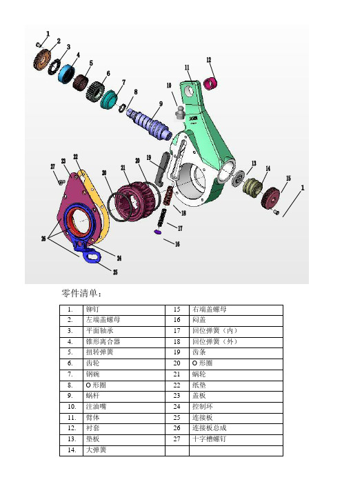
零件清单:1.铆钉15 右端盖螺母2.左端盖螺母16 闷盖3.平面轴承17 回位弹簧(内)4.锥形离合器18 回位弹簧(外)5.扭转弹簧19 齿条6.齿轮20 O形圈7.钢碗21 蜗轮8.O形圈22 纸垫9.蜗杆23 盖板10.注油嘴24 控制环11.臂体25 连接板12.衬套26 连接板总成1.起始位置连接板25被固定在支架上,齿条19与控制环24的槽口上端相接触。
槽口的宽度决定了刹车片与制动鼓之间的设定间隙值。
2.转过间隙角调整臂转过角A。
此时,齿条19向下运动与控制环24的槽口下端接触,制动蹄张开。
当存在超量间隙时,刹车片与制动鼓尚末接触。
3.转过超量间隙角B调整臂继续转动。
此时,齿条19已和控制环24的槽口下端接触(控制环与固定的控制臂被铆为一体),不能继续向下运动。
齿条驱动齿轮6旋转,单向离合器在这个方面可以相对自由转动转过角B后,凸轮轴带动制动蹄进一步张开,致使刹车片与制动鼓相接触。
4.转入弹性角C当调整臂继续转动时,由于刹车片与制动鼓已经相接触,作用在凸轮轴和蜗轮上的力矩迅速增加,蜗轮21作用于蜗杆9上的力(向右)随之增大,使得蜗杆压缩弹簧14并向右移动,从而导致蜗杆9与锥形离合器4分离。
5.转弹性角C调整臂继续转动时,齿条被控制环限制仍然不能向下运动而驱动齿轮转动。
这时由于锥形离合器4与蜗杆9处于分离状态,整个单向离合器总成一起转动。
6.向回转过弹性角C制动开始释放,调整臂向回转过角C。
在回位弹簧17和18的作用下,使得齿条向下紧帖控制环24的槽口下端。
此时,锥形离合器4与蜗杆9仍处于分离状态,齿条可以驱使单向离合器总成自由转动。
7.向回转入间隙角A随着刹车片作用于制动鼓上压力的释放,作用于凸轮轴和蜗轮的力矩消失,蜗轮21向右施加给蜗杆9的力也消失,弹簧14复原,推动蜗杆向左移动,使得蜗杆与锥形离合器4从新啮合。
8.向回转过间隙角A调整臂向回转过A。
齿条19向上运动,与控制环24的槽口的接触从下端变为上端。
自动调整臂使用方法及常见问题的判断与处理
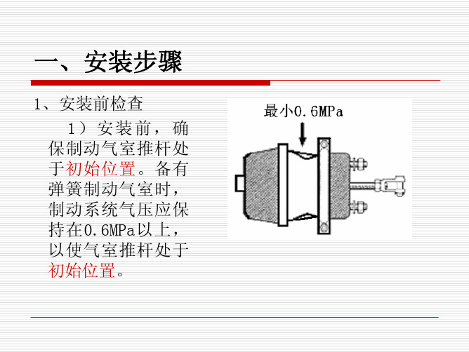
安装过程中可能产生的错误
2、气室推杆U形叉的定位孔与调整臂上孔未对正时, 试图强行插入圆柱销。 纠正方法:顺、逆时针旋转蜗杆六角头,在调整臂柄 部的孔与U形叉的轴销孔自然正对时,再将圆柱销轻 松插入U形叉孔,锁上开口销。调整时,若气室推杆 过长,U形叉挡住调整臂时,此时,可旋转U形叉后 退一定距离 。
二、拆卸步骤
1.拆下制动气室上连接的开口销、圆柱插销,使制动 气室与调整臂分离。 2.拆下凸轮轴端部的轴向定位螺栓和垫片(或垫片和 轴用卡簧)。 3.用SW12的扳手逆时针方向转动蜗杆六角头(转动时 所要的力矩较大,会听到咔咔声),直至调整臂柄 部从气室推杆U形叉中脱开。 4.拆下控制臂与定位支架相连的支撑螺栓、螺母、垫 片。最后将调整臂从凸轮轴中取出。
安装步骤
4、控制臂固定 1) 将控制臂向制动 方向推动(控制臂上有 箭头示意推动方向)直 到推不动为止。
安装步骤
注意:此时,控制臂 上指针应指向开口 或控制臂上的刻线 与控制臂盖上的刻 线对齐。其操作目 的是使自动调整臂 正常工作、免受破 坏。
安装步骤
2)安装调整臂支架, 随后将控制臂紧固 在定位支架上。
制动系统常见故障
症状 原因 措施
检查凸轮轴工作情况 调整行程 更换摩擦片 检查气功管路及各气阀 校正摩擦片贴合位置或磨合 清洗油迹和更换摩擦片 在行驶过程中,轻轻地踩下踏 板,使水排干
制动器 凸轮轴旋转不灵活 制动力 不足 制动气室推杆行程调整不当 制动摩擦片过热或变质 制动气压不够或气量不足 制动摩擦片贴合不当 在摩擦片或制动鼓上有润滑油 制动鼓进水
一侧油封漏油,致使制动鼓与摩擦片有油 更换新摩擦片,清洁并烘干制动鼓内表 污。 面。 左右轮胎气压是否一致。 充气使左右车轮气压相等。
克诺尔BENDIX 自动间隙调整臂安装指导 ASA5系列
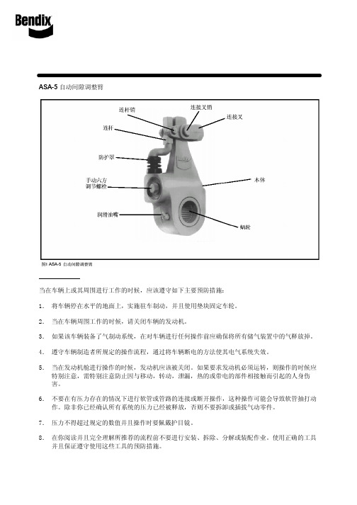
安装指导 ASA-5自动间隙调整臂重要! 请阅读 当在车辆上或其周围进行工作的时候,应该遵守如下主要预防措施:1.将车辆停在水平的地面上,实施驻车制动,并且使用垫块固定车轮。
2.当在车辆周围工作的时候,请关闭车辆的发动机。
3.如果该车辆装备了气制动系统,在对车辆进行任何操作前应确保将所有储气装置中的气释放掉。
4.遵守车辆制造者所规定的操作流程,通过将车辆断电的方法使其电气系统失效。
5.当在发动机舱进行操作的时候,发动机应该被关闭。
如果要求发动机必须运转,则操作的时候应特别注意,需特别注意防止因与移动,转动,泄漏,热的或带电的部件相接触而引起的人身伤害。
6.不要在有压力存在的情况下进行软管或管路的连接或断开操作,这种操作可能会导致软管抽打动作。
除非你已经确认所有系统的压力已经被释放,否则不要拆卸或插拔气动零件。
7.压力不得超过规定的数值并且操作时要佩戴护目镜。
8.在你阅读并且完全理解所推荐的流程前不要进行安装、拆除、分解或装配作业。
使用正确的工具并且保证遵守使用这些工具的预防措施。
9.使用正牌Bendix零件,部件和组件。
进行硬件,管件,软管和接头等部件的更换时,所更换的部件应同原厂采用的部件尺寸相同,类型相同并且强度相同。
这些部件是专门为了特定的应用和系统而设计的。
10.对于螺纹破裂或零件损坏的部件应予以更换而不是进行修理。
除非得到车辆或部件制造商的特别批准或许可,否则不要进行加工或焊接的修理。
11.在重新使用车辆前,应确保所有的部件和系统均恢复到正常的工作状态。
ASA-5的更换准备 在遵守以下注意事项的前提下,该Bendix ASA-5自动间隙调整臂可用来替换手动间隙调节装置或其他厂家的自动间隙调节装置:1.过多的工作循环,施加过高的压力或应用制动组合会减少自动间隙调整臂的使用寿命。
2.确定车辆的AL系数被更新至等于或小于195。
AL系数的计算方法为:将自动间隙调整臂的臂长(从凸轮轴花键的中心至连接叉销孔中心)乘以制动气室尺寸。
Yaskawa Motoman 机械臂控制器用户指南说明书

Step 30. Select the Deviation Control Type Submenu Press d . If flashing _DEV Deviation is displayed press a ,otherwise press b until flashing _DEV is shown. Now press d to store and go to next menu item.Step 31. Select the Latched Type SubmenuPress d . If flashing UNLT Unlatched is displayed press a ,otherwise press b until UNLT is displayed.Press d to store and advance to next menu item.Step 32. Select the Normally Open Type of Contact Closure SubmenuPress d . If flashing N.o.Normally Open is displayed,press a , otherwise press b until N.o.is displayed. Press d to store and advance to next menu item.Step 33. Select the Above Type of Active Submenu Press d . If flashing ABoV Above is displayed, press a ,otherwise press b until ABoV is displayed. Press d to store and advance to next menu item.Step 34. Enable Alarm 1 at Power On (A.P.oN )Press d . If flashing ENBL is displayed, press a , otherwise press b until ENBL is displayed. Press d to store and advance to next menu item.Step 35. Enter Alarm 1 High SubmenuPress a twice to skip ALR.L Alarm 1 Low value. ALR.L is for below & ALR.H for above.Step 36. Set the Alarm 1 High value (ALR.H )Press d . Press b or c until value to set the display to 002.0. Press d to save.Step 37. Enter the Alarm 2 MenuThe display will show ALR2the top menu for Alarm 2.Repeat steps from 28 to 36 to set for Alarm 2 the same conditions as for Alarm 1.Step 38. Skip the Loop Break Time Menu (LOOP )Press a to go to the OUT1Output 1 Menu item.Step 39. Configuration the Output 1 MenuSet Alarm 1 Disabled (Step 29) to be able to Enable Output 1.Configure Out 1 as CTRL / PID , ACTN / RVRS , AUTO /DSBL , ANTL / ENBL , PRoP / 005.0, REST / 0180, RATE /018.0, CYCL / 0010and DPNG / 0003. Please refer to the operator’s manual if needed. Press d to save and go to the next menu item.Step 40. Configuration of Display Color Selection Press a until the COLR Display Color Selection Menu appears on the Display. Configure COLR as N.CLR /GRN (green), 1.CLR / RED (red), 2.CLR /AMBR (amber). Please refer to the operator’s manual if needed.For color change on Setpoints refer to Owners Manual Section 2.Step 41. Run a TestPress a until reset the controller and return to RUN Mode to display 075.0(Ambient Temperature). Now you are ready to observe temperature as it rises 10°F higher thandisplayed. Touch the tip of the Thermocouple to raise the temperature above the Alarm 2 High value 082.0, and AL2will turn on, and Display Color will change from Green to Amber. Continue touching the tip to raise the temperature above the Alarm 1 High value 087.0and Display Color will change from Amber to Red. Annunciator “1” is turning on and off displaying output 1.Step 11. Enter to the Thermocouple Type Input Submenu Press d to display flashing, previously selected Thermocouple type.Step 12. Scroll through available selection of TC types Press b to sequence thru flashing Thermocouple types,(select k -for type "K" CHROMEGA ®/ALOMEGA ®)J K T E N DIN J R S B C - TC types J k t E N dN J R S b C - DisplayStep 13. Store TC typeAfter you have selected the Thermocouple type press d to store your selection, the instrument automatically advances to the next menu item.Step 14. Enter to Reading Configuration MenuThe display shows RDG Reading Configuration, which is the top menu for 4 submenus: Decimal Point, Degree Units,Filter Constant and Input/Reading Submenus.Step 15. Enter to Decimal Point Submenu Press d to show DEC Decimal Point.Step 16. Display the Decimal Point positionPress d again to display the flashing Decimal Point position.Step 17. Select the Decimal Point position Press b to select FFF.F Decimal Point position.Step 18. Store selected Decimal Point positionBy pressing d momentarily the Decimal Point position will be stored and the instrument will go to the next menu item.Step 19. Enter to Temperature Unit Submenu Display shows TEMP Temperature Unit.Step 20. Display available Temperature Units Press d to display the flashing Degree °F or °C .Step 21. Scroll through Temperature Units selection Press b to select °F Degree.Step 22. Store the Temperature UnitPress d to display momentarily that the Degree Unit has been stored and the instrument will go automatically to the next menu item.Step 23. Enter the Filter Constant Submenu Display shows FLTR Filter Constant Submenu.Step 24. Display the Filter Constant Value Submenu Press d to display the flashing, previously selected Filter Constant.Step 25. Scroll through available Filter Constants Press b to sequence thru Filter Constants 0001, 0002,0004, 0008, 0016, 0032, 0064and 0128.Step 26. Store the Filter ConstantPress d momentarily to store 0004Filter Constant and the instrument will automatically go to the next menu item.Step 27. Enter Alarm 1 MenuThe display will show ALR1the top menu for Alarm 1. In the following steps we are going to enable Alarm 1, Deviation,Unlatch, Normally Open, Active Above, Enable at power on and +2°F High Alarm i.e. Process Value > Setpoint 1 Value +2°F will activate Alarm 1.If Analog Output Option is installed and enabled, the controller will skip Alarm 1 Menu item to Analog Output.Step 28. Enter Alarm 1 Enable/Disable Submenu Press d to display flashing DSBL / ENBL .Step 29. Enable Alarm 1 SubmenuIf flashing ENBL is displayed, press a , if DSBL is displayed,press b until ENBL is displayed, then press d to store and go to the next menu item.MQS3849/0206SPECIFICATIONAccuracy:+0.5°C temp;0.03% rdg. process typical Resolution:1°/0.1°; 10 µV process Temperature Stability:0.04°C/°C RTD;0.05°C/°C TC @ 25°C (77°F); 50 ppm/°C processiDRP Remote Programmer/Display Option:4-digit, 9-segment LED 21 mm (0.83"), 48H x 96W x 39D (1.89 x 3.78 x 1.55”),159g (0.35lbs). Red, green, and amber programmable colors for processvariable, setpoint and temperature units Input Types:Thermocouple, RTD, Analog Voltage and Current TC:(ITS 90)J, K, T, E, R, S, B, C, N, L RTD:(ITS 68)100/500/1000 ohm Pt sensor2-, 3-, or 4-wire; 0.00385 or 0.00392curve Voltage:0 to 100 mV, 0 to 1 V, 0 to 10 Vdc Current:0 to 20 mA (4 to 20 mA)Output 1:Relay 250 Vac @ 3 A Resistive Load,SSR, Pulse, Analog Voltage and Current Output 2:Relay 250 Vac @ 3 A Resistive Load,SSR, PulseOptions:Communication RS-232 / RS-485 or 10BaseT or Excitation:24 Vdc @ 25 mAEXC. not available for Low Power OptionLine Voltage/Power:90 - 240 Vac ±10%,50 - 400 Hz*, or 110 - 375Vdc, 4W* No CE compliance above 60 HzLow Voltage Power Option:12-36 Vdc, 3 W****Units can be powered safely with 24 Vac but No Certification for CE/UL are claimed.Dimensions:Standard Unit iDR:92.5H x 125.2D x 24.9mm W(3.64 x 4.93 x 0.98”); 181 g (0.4 lb)Ethernet Unit iDR-EI/C4EI:92.5H x 125.2D x 39.8mm W(3.64 x 4.93 x 1.55”); 204 g (0.45 lb)Approvals:UL, C-UL, CE per EN 61010-1:2001WARNING:These products are not designed for use in, and should not be used for, patient-connected applications.It is the policy of OMEGA to comply with all worldwide safety and EMC/EMI regulations that apply.OEMGA is constantly pursuing certification of its products to the European New Approach Directives.OMEGA will add the CE mark to every appropriate device upon certification.The information contained in this document is believed to be correct, but OMEGA Engineering,Inc.accepts no liability for any errors it contains, and reserves the right to alter specifications without notice.TRADEMARK NOTICE:®,®,, andare Trademarks ofOMEGA ENGINEERING, INC.®USAMADE INThis Quick Start Reference provides information on setting up your instrument for basic operation. The latest complete Communication and Operational Manual as well as free Software are available at/specs/iseries or on the CD-ROM enclosed with your shipment .SAFETY CONSIDERATIONThe instrument is protected in accordance with EN 61010-1:2001, electrical safety requirements for electrical equipment for measurement, control andlaboratory.Remember that the unit has no power-on switch.Building installation should include a switch or circuit-breaker that must be compliant to IEC 947-1 and 947-3.SAFETY:•Do not exceed voltage rating on the label located on the side of the instrument housing.•Always disconnect power before changing signal and power connections.•Do not use this instrument on a work bench without its case for safety reasons.•Do not operate this instrument in flammable or explosive atmospheres.•Do not expose this instrument to rain or moisture.EMC:•Whenever EMC is an issue, always use shielded cables. •Never run signal and power wires in the same conduit.•Use signal wire connections with twisted-pair cables.•Install Ferrite Bead(s) on signal wire close to the instrument if EMC problems persist. MOUNTING1) Tilt unit, position mounting slot onto DIN Rail, as shown.2) Push unit towards DIN Rail and it will snap into place.1) 2)。
SAE自动调整臂
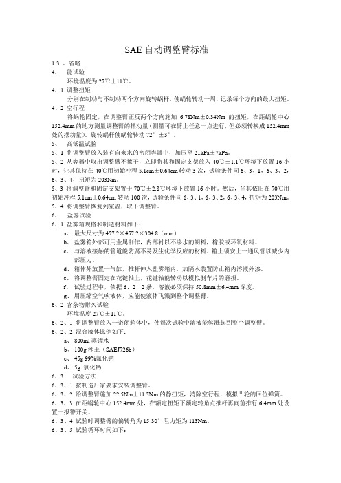
SAE自动调整臂标准1-3 、省略4、能试验环境温度为27℃±11℃。
4、1 调整扭矩分别在制动与不制动两个方向旋转蜗杆,使蜗轮转动一周,记录每个方向的最大扭矩。
4、2 空行程将蜗轮固定,在调整臂正反两个方向施加 6.78Nm±0.34Nm的扭矩,在距蜗轮中心152.4mm的地方测量调整臂的摆动量(测量可在臂上任意一点进行,但必须转换成152.4mm 处的摆动量)。
旋转蜗杆使蜗轮转动72°±3°。
5、高低温试验5、1 将调整臂放入装有自来水的密闭容器中,加压至21kPa±7kPa。
5、2 从容器中取出调整臂不擦干,立即将其和固定支架放入-40℃±1.1℃环境下放置16小时,让其保持在-40℃用初始冲程5.1cm±0.64cm转动3次,试验条件同6、3、1,6、3、2,6、3、4,扭矩为203Nm。
5、3 将调整臂和固定支架置于70℃±2.8℃环境下放置16小时。
然后,当其依旧在70℃用初始冲程5.1cm±0.64cm转动100次,试验条件同6、3、1,6、3、2,6、3、4,扭矩为203Nm。
5、4 将调整臂恢复到室温,取下调整臂。
6、盐雾试验6、1 盐雾箱规格和制造材料如下:a、最大尺寸为457.2×457.2×304.8(mm)b、盐雾箱外部可用金属制作,内部衬以不渗水的朔料,橡胶或环氧材料。
c、与溶液接触的管道能防腐不易发生化学反应的材料。
箱上须安上一通风管以减少内部压力。
d、箱体外放置一气缸,推杆伸入盐雾箱内,加隔水装置防止箱内溶液外渗。
e、将调整臂固定在花键轴上,花键轴能转动以模拟刹车片的磨损。
f、试验过程中,依据6、2、2条,溶液必须保持50.8mm±6.4mm深度。
g、用压缩空气吹液体,应能使液体飞溅到整个调整臂。
6、2 含杂物耐久试验环境温度27℃±11℃。
正确使用自调臂
正确使用自动调整臂一、背景GB12676-1999《汽车制动系统结构、性能和试验方法》中第4.2.11.1条要求,“行车制动器的磨损应能自动补偿。
”为满足法规要求,从2003年6月起,东风商用车在天龙和部分大力神车型采用了自动调整臂(以下简称“自调臂”)。
自调臂能使摩擦片与制动鼓之间的间隙保持到预留值,对用户而言,可以节约大量维护和保养时间,提高运营经济效益。
东风商用车技术中心根据市场赔偿、厂家反馈、故障件检测等信息,发现部分用户在使用自调臂时,没有完全了解该产品的使用方法,本文主要介绍了在使用过程中应注意的一些事项。
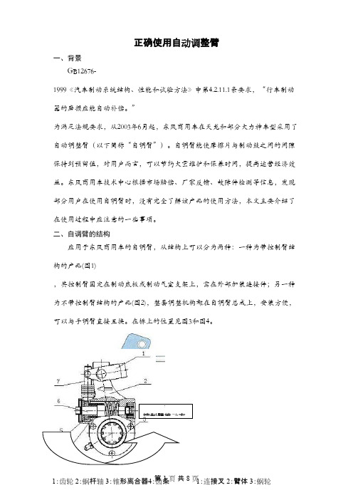
二、自调臂的结构应用于东风商用车的自调臂,从结构上可以分为两种:一种为带控制臂结构的产品(图1),其控制臂固定在制动底板或制动气室支架上,需在外部加装连接件;另一种为不带控制臂结构的产品(图2),整套调整机构都在自调臂总成上,安装方便,可以与手调臂直接互换。
在桥上的位置见图3和图4。
控制臂推动方图1 带控制臂类结构示意图图2 不带控制臂类结构示意图图3 带控制臂类自调臂在桥上的位置图4 不带控制臂类自调臂在桥上的位置三、自调臂的拆卸方法维护制动器需要拆下自调臂时,请按如下步骤从桥上拆下自调臂。
1、带控制臂类(图5)①解除制动,拆下制动气室推杆和自调臂连接的开口销、销轴,将制动气室与调整臂分开;②拆下凸轮轴端部轴向定位的垫片和卡簧;③用手动扳手逆时针方向旋转蜗杆轴(转动时力矩较大,会听到“咔咔”声),直至调整臂柄部从推杆连接叉中完全离开;④拆下固定控制臂的螺栓,取下调整臂。
图5 带控制臂类自调臂安装爆炸图2、不带控制臂类(图6)①解除制动,拆下制动气室推杆和自调臂连接的大、小开口销和大、小销轴,将制动气室与调整臂分开;②拆下凸轮轴端部轴向定位的垫片和卡簧;③用手动扳手旋转蜗杆轴,取下齿条,直至调整臂柄部从推杆连接叉中完全离开,取下调整臂。
图6 不带控制臂类自调臂安装爆炸图1:连接叉和备紧螺母 2:臂体 3:凸轮轴 4:卡簧5:螺栓-固定控制臂 6:弹簧垫圈c :专用连接叉 f :气室推杆 g :备紧螺母 h :大销轴 i :小销轴 j :卡簧 k :凸轮轴四、自调臂的安装方法安装自调臂时,必须先将自调臂套在凸轮轴花键上,通过旋转自调臂蜗杆轴,使自调臂的销孔和气室连接叉销孔对齐后,再连接自调臂和气室,具体方法如下。
刹车间隙自动调整臂使用维修说明书
刹车间隙自动调整臂使用维修说明书欧曼营销公司服务管理部2008年3月目 录第一章 刹车间隙自动调整臂安装步一 (1)第二章 刹车间隙自动调整臂拆卸步骤 (4)第三章 刹车间隙自动调整臂的保养 (4)第四章 安装刹车间隙自动调整臂过程的注意事项 (4)第五章 常见故障及处理指南 (5)第一章 刹车间隙自动调整臂的安装1.安装前,确保制动分泵推杆处于初始位置。
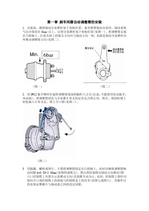
备有弹簧制动分泵时,制动系统气压应保持在6b a r以上,以使分泵推杆处于初始位置(见图一)。
把调整臂安装在凸轮轴上。
注意壳体上的箭头方向应与制动方向一致,也就是制动分泵推杆向外推动调整臂方向(见图二)。
(图一) (图二)2.用S W l2扳手顺时针旋转调整臂端部的蜗杆六方头(注意:不能使用电动扳手,风动钻),使调整臂的孔与分泵推U形叉的定位孔自然正对,然后,将园柱销上轻松插入U形叉孔,锁上开口销(见图三)。
(图三)3用隔圈、螺栓或垫片、卡簧将调整臂固定在凸轮轴上,此时应确保调整臂轴向间隙A=0.50-2.00m m(见图四或图五),然后将控制臂向制动方向推动(图六)(控制臂上有箭头示意推动方向)直到推不动为止。
此时,控制臂上指针应指向开口或控制臂上的刻线与控制臂盖上的对齐(见图七或图八)。
其操作目的是保证摩擦片与制动鼓之间的设定间隙。
(图四)(图五)(图六)(图七)(图八)4.安装调整臂支架,随后将控制臂紧固在定位支架上(见图九)。
(图九)5.用扳手顺时针转动调整臂蜗杆六角头直至摩擦片与制动鼓接触,然后再逆时针方向转动蜗杆六角头3/4圈(反向转动时会听到咔咔声)(见图十)。
注意:不能使用电动扳手、风动钻!(图十)6. 施加若干次(约5次)制动,刹车间隙自动调整至正常范围,调整功能可通过蜗杆六角头在刹车即将结束时顺时针力向自动旋转观察到,至此安装过程结束。
(见图十一)(图十一)第二章刹车间隙自动调整臂的拆卸1.拆下制动分泵上连接的开口销、圆柱插销,使制动分泵与调整臂分离。
John Deere 700FD 灵活摆臂平台使用说明说明书

1. Press the side belt speed reduction button (A) on the multi-function lever.
Refer to your Operator’s Manual for additional information.
Adjustments
Draper Ground Engagement Angle
The HydraFlex™ Draper engagement angle is designed for optimum performance on your combine. It is recommended that the factory feeder house fore/aft tilt frame setting be used. If adjustments are desired, refer to your combine Operator’s Manual for proper instructions.
Reel finger pitch is adjustable. Adjustment levers are at both ends of the reel. A more advanced finger pitch helps pick up downed crop. A less advanced pitch reduces the material wrapping on the reel.
自动间隙调整臂的使用ppt课件

8
C、 用合适扳手顺时针方向转动(转动时可听见“哒哒” 声) 调整 臂的六角头直至摩擦衬片与制动鼓接触,然后再逆时 针方向转 动(转动时会听到“咔咔”声)六角头1圈(见图 5)。注意: 不能使用电动扳手。 图5
9
5、 施加若干次制动,制动(刹车)间 隙将自动调整至正常范围,调整 功能可通过六角头在制动即将结束 时顺时针方向的自动 旋转观察到。 至此安装过程结束。
7
安装步骤 A、 用合适的扳手顺时针旋转调整臂端
部六角头——此时可听见 “哒哒”声(注意:不能使用电动 扳手),使调整臂销孔与销 孔对正,然后 在圆柱销上涂上黄油,轻轻插入叉孔,锁 上开口销。(见图5) B、 用调整垫片和卡簧将调整臂固定在花键端, 检查调整臂回位是 否灵活,然后按控制臂 上的箭头方向推动控制臂直到推不动为止 (标记对齐),锁紧安装支架(见图5)。上 述操作目的是保证摩擦衬片与制动鼓间的设 定间隙。
5
2. 在凸轮轴花键端部涂上黄油,然后将调整臂 的定位支架用螺栓安装于汽车底盘上,注意 这时螺栓不拧紧,使定位支架可以在螺栓上。
(见下图)
6
3、 把调整臂套在花键端(花键端需要涂上黄油), 调整臂销孔与调整拨叉销孔有一段位移量;将控 制 臂安装在定位支架上,调整壳体上的箭头方向 应与制动方向一致,也就使制动分泵推杆向外推 动调整 臂的E为弹性变形区,Ce磨损区, C为正常间隙。间隙式制动间隙自动调整臂 能精确记录由于摩擦衬片磨损及自身的弹性 变形量而引起的间隙增加量,并且精确地将 间隙调整至正常范围。 本
3
自动间隙调整臂有如下优点: 1.自动保持制动蹄片和制动鼓之间的间隙
恒定,因而使制动安全可靠。 2.制动分泵推杆行程短,使制动迅速可靠。 3.减少压缩空气的损耗,延长了空压机、
自动调整臂

四、 自动调整臂安装及注意事项
自动调整臂安装 3、将控制臂按制动时自调 臂转动方向转到极限位置后, 用螺栓将控制臂与连接板固定。
4、顺时针转动蜗杆六角头, 带制动凸轮轴转动,使制动蹄 与制动鼓接触,再回转(逆时 针)3/4圈。
四、 自动调整臂安装及注意事项
自动调整臂安装
四、 自动调整臂安装及注意事项
谢谢!
二、 自动调整臂的结构
在手动调整臂基础上,增加了离合齿轮、驱动齿轮、 齿条、单向离合器、控 制滑环等。
离合齿轮 齿条 控制臂 齿条
间隙
二、 自动调整臂的结构
控制臂
自调臂总成
二、 自动调整臂的结构
一代调整臂结构
9 蜗杆 10 油杯 11 壳体 1 铆钉 12 加强圈 2 螺盖 13 止推垫片 3 轴承 14 止推弹簧 4 锥形离合器 15 调整端螺盖 5 离合器弹簧 16 闷盖 6 齿轮 17 复位弹簧(内) 7 轴套 18 复位弹簧(外) 8 O型圈(Ⅰ) 19 齿条
气制动自动调整臂简介
2012年03月23日
一、 自动调整臂的优点
自动保持摩擦片和制动鼓之间间隙恒定,因而刹车安 全可靠。
压缩空气的损耗小,延长了空气压缩机、制动分泵和 压缩空气系统中其它部件的寿命。
制动迅速可靠,使所有车轮的制动效果一致、稳定。
安装方便。 安装过程结束,不再需要人工调节刹车调整臂,减少 了维修次数,保养车辆的时间间隔得以延长,从而提高 了经济效益。
调整臂向回转过角“A”,齿条“19” 向上运动,与控制环“24”的槽口的接 触从下端变为上端。
三、 自动调整臂的工作原理
9 向回转过超量间隙角“B” 调整臂继续转动回到起始位置。此时, 齿条“19”已与固定的控制环“24”的 槽口上端相接触,受其限制不能继 续向上移动。当调整臂回转时,齿 条驱动齿轮“6”转动,此时单向 离合器和锥齿离合器均处于啮合状 态,使得蜗杆“9”随齿轮一起转 动,蜗杆驱动蜗轮“21”,蜗轮驱动 凸轮轴,而凸轮轴的转动使得超量 间隙减小,自动调整臂工作结束。
自动化机械臂P5G系列夹紧器用户操作手册说明书

Automation ActuatorDivisionTABLE OF CONTENTS1. INSPECTION AND REPLACEMENT PROCEDURE FOR 30 DEGREE ANGULAR GRIPPER.(A) FOR PROX OPTIONS SEE SECTION 2C.2. INSPECTION AND REPLACEMENT PROCEDURE FOR 180 DEGREE ANGULARGRIPPER.(A) STROKE ADJUST FRONT.(B) STROKE ADJUST REAR.(C) PROXIMITY OPTIONS.3. INSPECTION AND REPLACEMENT PROCEDURE FOR PARALELL GRIPPER.(A) FUNCTION DRAWINGS.(B) STROKE ADJUST FRONT.(C) STROKE ADJUST REAR.(D) PROXIMITY OPTIONS.4. FASTENER TORQUE TABLES.DRAWING INDEXDRAWING 1: STANDARD 30 DEG ANGULAR GRIPPER.DRAWING 2: STANDARD 180 DEG ANGULAR GRIPPER.DRAWING 3: STANDARD 180 DEG ANGULAR GRIPPER, STROKE ADJUST FRONT.DRAWING 4: STANDARD 180 DEG ANGULAR GRIPPER, STROKE ADJUST REAR.DRAWING 5: STANDARD 30/180 DEG ANGULAR GRIPPER, PROXIMITY OPTIONS.DRAWING 6: STANDARD PARALELL GRIPPERDRAWING 7: STANDARD PARALELL GRIPPER, STROKE ADJUST FRONT.DRAWING 8: STANDARD PARALELL GRIPPER, STROKE ADJUST REAR.DRAWING 9: STANDARD PARALELL GRIPPER, PROXIMITY OPTIONS.NOTE: THIS MANUAL COVERS BASIC GRIPPER CONFIGURATIONS ONLY. SPRING ASSIST AND SPRING RETURN OPTIONS ARE NON USER SERVICEABLE. RETURN SPRING ASSIST AND SPRING RETURN OPTION GRIPPERS TO FACTORY FOR DISPOSITION ANDMAINTENANCE.Automation ActuatorDivision30 Degree Angular Gripper1.GENERALGrippers are position sensors ready with magnetic pistons. Each size uses a standardized sensor groove to accept Hall Effect, reed or proximity sensors. Optional Prestolock flowcontrol fittings provide smooth and controlled jaw action. For high temperature service,fluorocarbon seals are available.2.SPECIFICATIONSq Operating pressure range: 0.3 to 7 bar (4 to 100 psi)q Operating characteristics: double acting, single actingq Mounting orientation: unrestrictedq Working ports: M5q Operating temperature rangeq Standard seals –20 to 82 degree Celsius (-4 degrees to 180 degree Fahrenheit)q Fluorocarbon seals –20 to 121 degree Celsius (-4 degrees to 250 degree Fahrenheit) q Filtration requirement: 40 micron filtered, dry air3. SECTION 1: INSPECTION AND REPLACEMENT PROCEDURE FOR 30 DEGREEANGULAR GRIPPERDisassembly:• Remove retaining ring (29).• Remove endcap (26).• Remove screw (22).• Remove piston assembly (20) from housing (17).• Remove 4 bolts (61).• Remove as a unit the guides (60), fingers (59) piston rod assembly (73) and rod endcap assembly (13)(14) (15), set aside on clean surface.• Clean and check all parts for excessive wear, replace if needed.A ssembly:• Apply a light coating of Accrolube Teflon Impregnated Grease to the seal groove in the piston assembly(20) and to the piston seal (21).• Install the piston seal on the piston assembly with the lettering facing the magnet.• Apply a light coating of grease to the piston rod seal (13) and install the seal in the Delrin endcap (14), cupped side first.• Apply grease to the o-rings (15) and install them on the endcaps (14) (26).• Install bumper (19) over piston rod assembly.Automation ActuatorDivision• Apply a light coating of grease to the piston rod assembly (73) and insert it in the Delrin endcap with the rod seal towards the dowel end.• Attach the piston assembly (20) to the piston rod assembly (73) using permanent threadlocker on the screw (22) and tighten to the proper torque.• Insert the piston and the Delrin endcap in housing.• Apply a light coating of grease to the pivot point surfaces of the finger subassemblies (58) (59).• Apply a heavy coating of grease to the pivot point holes in the guides (60). (Note: click here to go to the proximity sensor section if your gripper has that option).• Insert a dowel (16) chamfered end first, into one of the guides.• Slide the guide with the dowel, and the fingers onto the piston rod assembly.• Slide the other guide onto the other side.• Apply removable threadlocker to four SHCS (61).• Push the guides into place on the housing and secure with the four SHCSs (61).• When tightening the screws, hold the guides together with light pressure. Tighten the screws to the proper torque.• Insert the remaining endcap (29) into the housing (17) and secure with the retaining ring.Automation ActuatorDivisionDRAWING 1BALLOON DESCRIPTION QUANITY BALLOON DESCRIPTION QUANITY 13ROD SEAL122PISTON FASTENER1 14ROD END CAP124BUMPER1 15O-RING226END CAP1 16DOWEL PIN229RETAINING RING1 17HOUSING159FINGER2 19BUMPER160GUIDE2 20PISTON ASSEMBLY161GUIDE FASTENER4 21PISTON SEAL173PISTON ROD1ASSEMBLYAutomation ActuatorDivision180 Degree Angular Gripper1.GENERALGrippers are position sensors ready with magnetic pistons. Each size uses a standardized sensor groove to accept Hall Effect, reed or proximity sensors. Optional Prestolock flowcontrol fittings provide smooth and controlled jaw action. For high temperature service,fluorocarbon seals are available.2.SPECIFICATIONSq Operating pressure range: 0.3 to 7 bar (4 to 100 psi)q Operating characteristics: double acting, single actingq Mounting orientation: unrestrictedq Working ports: M5q Operating temperature rangeq Standard seals –20 to 82 degree Celsius (-4 degrees to 180 degree Fahrenheit)q Fluorocarbon seals –20 to 121 degree Celsius (-4 degrees to 250 degree Fahrenheit) q Filtration requirement: 40 micron filtered, dry air3. SECTION 2: INSPECTION AND REPLACEMENT PROCEDURE FOR 180 DEGREEANGULAR GRIPPERDisassembly:• Remove retaining ring (29).• Remove endcap (26).• Remove screw (22).• Remove piston assembly (84) from housing (17).• Remove 4 bolts (72).• Remove as a unit the guides (77), fingers (74), levers (76), piston rod assembly (78) and rod endcap assembly (13) (14) (15), set aside on clean surface.• Clean and check all parts for excessive wear, replace if needed.A ssembly:• Apply a light coating of Accrolube Teflon Impregnated Grease to the seal groove in the piston assembly(84), and to the piston seal (21).• Install the piston seal on the piston assembly with the lettering facing the magnet.• Apply a light coating of grease to the piston rod seal (13) and install the seal in the Delrin endcap (14).• Apply grease to the o-rings (15) and install them on the endcaps (14) (26).• Install bumper (19) over piston rod assembly.• Apply a light coating of grease to the piston rod assembly (78) and insert it in the Delrin endcap with the rod seal towards the dowel end.• Attach the piston assembly (84) to the piston rod assembly using permanent threadlocker on the screw(22) and tighten to the proper torque.Automation ActuatorDivision• Insert the piston and the Delrin endcap in housing.•Apply a light coating of grease to the pivot point surfaces of the finger/lever assemblies (74) (76).• Apply a heavy coating of grease to the pivot point holes in the guides (77).• Insert a dowel (16) chamfered end first, into one of the guides. (Note: click here to refer to the section on proximity sensors if it pertains to your gripper.)• Slide the guide with the dowel, the fingers and the levers onto the piston rod assembly.• Slide the other guide onto the other side. (Note: click here to refer to the section on stroke adjust front if it pertains to your gripper.)• Apply removable threadlocker to four SHCS (72).• Push the guides into place on the housing (17) and secure with the four SHCSs (72). When tightening the screws, hold the guides together with light pressure.• Tighten the screws to the proper torque. (Note: click here to refer to the section on stroke adjust rear if it pertains to your gripper.)• Insert the remaining endcap (26) into the housing and secure with the retaining ring (29).Automation ActuatorDivisionDRAWING 2BALLOON DESCRIPTION QUANITY BALLOON DESCRIPTION QUANITY 13ROD SEAL126END CAP1 14ROD END CAP129RETAINING RING1 15O-RING272FASTENERS4 16DOWEL PIN274FINGER2 17HOUSING175DOWEL2 19BUMPER176LEVER2 21PISTON SEAL177GUIDE2 22PISTON FASTENER178PISTON ROD ASSEMBLY1 24BUMPER184PISTON ASSEMBLY1Automation ActuatorDivisionSTROKE ADJUST FRONTDRAWING 3SECTION 2A: STROKE ADJUST FRONT• Install the stroke adjust cap (80) on top of the guides.• Apply removable threadlocker to the last 3-4 threads of fasteners (79) and tighten to proper torque.• Install set screw (83), flat washer (81) and jamnut (82) so that the piston has a full stroke. Tighten jam nut.Automation ActuatorDivisionSTROKE ADJUST REARDRAWING 4SECTION 2B: STROKE ADJUST REAR•Screw the peened set screw (33) fully into the end cap (28) so the peened end is in the counter bore.•Install the sealing washer (30), flat washer (31) and jam nut (32) on the outside of the setscrew.•Tighten the jam nut.•Apply a light coating of grease to the o-ring groove in the end cap and the o-ring(15). Install the o-ring on the end cap and insert into the housing. Install theretaining ring (29) into the housing.Automation ActuatorDivisionPROXIMITY SENSORDRAWING 5SECTION 2C: PROXIMITY SENSORS• Insert a dowel (*16) chamfered end first, into the guide containing the clearance holes for the finger pivot dowel.• Slide the guide with the dowel, (and the fingers with the longer end of the dowel protruding out of the guide), onto the piston rod assembly, and facing up towards the slots on the housing.• Slide the other guide onto the other side.• Apply removable threadlocker to four SHCS.• Push the guides into place on the housing and secure with the four SHCSs (*61). When tightening the screws, hold the guides together with light pressure.• Tighten the screws to the proper torque.• Insert the remaining endcap (*29) into the housing (*17) and secure with the retaining ring.• Attach both sensor flags (67) to the pivot pins (65A) of the fingers. Mount proximity sensors and bracket(71) with 1mm clearance between sensor and nearest flag surface.*SEE DRAWING 1 FOR 30 DEGREE GRIPPER*SEE DRAWING 2 FOR 180 DEGREE GRIPPERAutomation ActuatorDivisionParallel Gripper1.GENERALGrippers are position sensors ready with magnetic pistons. Each size uses a standardizedsensor groove to accept Hall Effect, reed or proximity sensors. Optional Prestolock flowcontrol fittings provide smooth and controlled jaw action. For high temperature service,fluorocarbon seals are available.2.SPECIFICATIONSq Operating pressure range: 0.3 to 7 bar (4 to 100 psi)q Operating characteristics: double acting, single acting, spring assistq Gripping force @ 6 Bar: 78 to 1086 N (17.5 to 244 lb.)q Mounting orientation: unrestrictedq Working ports: M5q Operating temperature rangeq Standard seals –20 to 82 degree Celsius (-4 degrees to 180 degree Fahrenheit)q Fluorocarbon seals –20 to 121 degree Celsius (-4 degrees to 250 degree Fahrenheit) q Filtration requirement: 40 micron filtered, dry air3. SECTION 3:INSPECTION AND REPLACEMENT PROCEDURE FOR PARALLEL GRIPPER Disassembly:• Remove retaining ring (29).• Remove endcap (26).• Remove screw (22).• Remove piston assembly (20) from housing (17).• Remove cover (1).• Remove 4 screws (3).• Remove as a unit the guide cap (4) guide (9), fingers (10), piston rod assembly (6) (7) (8) and rod endcap assembly (13) (14) (15), set aside on clean surface.• Clean and check all parts for excessive wear, replace if needed.A ssembly:• Apply a light coating of Accrolube Teflon Impregnated Grease to the seal groove in the piston assembly (20) and to the piston seal (21).• Install the piston seal on the piston assembly with the lettering facing the magnet. Set aside on a clean surface.Automation ActuatorDivision• Apply a light coating of grease to all surfaces of the fingers (10) except the face with the tapped holes.• Apply a heavy coating of grease in the finger slot. Set aside on a clean surface.• Press two dowels (16) chamfered end first, into guide (9) if the fit requires it.• Apply a light coating of grease to the inside channel surfaces of the guide and a heavy coating of grease in the slots of the guide.• Temporarily set the guide in position on top to the housing (17).• Apply a light coating of grease to all surfaces of the piston rod assembly (6) except the tapped end.• Install a bronze spacer (7) on each end of the piston rod assembly and slide against the piston rod.• Install the fingers on the piston rod assembly according to the function drawings.See function drawings in Section 3A.Apply a light coating of grease on each bearing (8) and install on the piston rod assembly.• Rotate the etched mark on the bearing so that the etched marks face opposite the tapped end of the piston rod.• Insert the piston rod assembly with fingers into the channel in the guide with the piston rod protruding through the floor of the guide (9). The etched marks on the bearing should be visible at the top of the guide track. If not, re-install.• Apply a light coating of grease to the o-ring grooves in the endcaps (14) (26) and the o-rings (15).• Install the o-rings on the endcaps (14) (26).• Insert the rod seal (13) into the pocket in the Delrin endcap (14), cupped side first. Set aside on a clean surface.• Remove the guide/finger assembly from the housing (17) and move the piston rod to maximum extension through the guide.• Install the Delrin endcap assembly over the piston rod assembly, seal end first, keeping grease clear of the tapped hole in the piston rod assembly.• Set guide/ finger assembly on a clean surface with the piston rod assembly up.• Set the piston assembly on top of the piston rod assembly, small counter bore to the rod.• Apply removable threadlocker to the last four threads of the screw (22) and tighten to proper torque.• Apply a light coating of grease to the bore of the housing (17).• Set housing on clean surface with bore vertical and two dowel holes up.• Install two dowels (16) in housing.• Insert guide/piston sub assembly into the housing.• Apply a light coating of grease to the flat side of the guide cap (4) keeping grease away from the holes.• Install the guide cap on top of the guide with the solid edge above the fingers.• Apply removable threadlocker to the last 3-4 threads of the four screws (3) and tighten per proper torque.• Apply a light coating of grease to the end cap (26) and the o-ring.Automation ActuatorDivision• Insert the endcap into the housing (17). Install the retaining ring (29) into the housing.• Install the cover (1) by stretching over the fingers.DRAWING 6BALLOON DESCRIPTION QUANITY BALLOON DESCRIPTION QUANITY 1COVER115O-RING23FASTENER416DOWEL PIN24GUIDE CAP117HOUSING1119BUMPER1 6PISTON RODASSEMBLY7SPACER220PISTON ASSEMBLY18BEARING221PISTON SEAL19GUIDE122PISTON FASTENER1Automation ActuatorDivision10FINGER224BUMPER1 13ROD SEAL126END CAP1 14ROD END CAP129RETAINING RING1 SECTION 3A: FUNCTION DRAWINGSF01 FINGER ARANGEMENTSTANDARD TRAVEL, MAXIMUM GRIP CLOSEDSAMPLE MODEL CODESP5G-AP4B AD NNSP5G-AP4B AE NNSP5G-AP4B AF NNSP5G-AP4B AG NNSP5G-AP4B AN NNS(MAN10.DWG)F01 FINGER ARANGEMENTSTANDARD TRAVEL, MAXIMUM GRIP OPENSAMPLE MODEL CODESP5G-AP4B BD NNSP5G-AP4B BE NNSP5G-AP4B BF NNSP5G-AP4B BG NNSP5G-AP4B BN NNS(MAN11.DWG)Automation ActuatorDivisionF03 FINGER ARANGEMENT EXTENDED TRAVEL, MAXIMUM GRIP OPENSAMPLE MODEL CODESP5G-AP4B DD NNSP5G-AP4B DE NNSP5G-AP4B DF NNSP5G-AP4B DG NNSP5G-AP4B DN NNS(MAN6.DWG)F02 FINGER ARANGEMENT EXTENDED TRAVEL, MAXIMUM GRIP CLOSEDSAMPLE MODEL CODESP5G-AP4B CD NNSP5G-AP4B CE NNSP5G-AP4B CF NNSP5G-AP4B CG NNSP5G-AP4B CN NNS(MAN9.DWG)Automation ActuatorDivisionDRAWING 7SECTION 3B: STROKE ADJUST FRONT•Install the stroke adjust guide cap (5) on top of the guide with the solid edge above the fingers.• Apply removable threadlocker to the last 3-4 threads of fasteners (3) and tighten to proper torque.• Cycle the gripper by hand. Should be smooth and easy to move. Install set screw (34), flat washer (31) and jam nut (32) so that the piston has a full stroke. Tighten jam nut.Automation ActuatorDivisionDRAWING 8SECTION 3C: STROKE ADJUST REAR• Screw the peened set screw (33) fully into the end cap (28) so the peened end is in the counter bore.• Install the sealing washer (30), flat washer (31) and jam nut (32) on the outside of the setscrew.• Tighten the jam nut.• Apply a light coating of grease to the o-ring groove in the end cap and the o-ring (15).• Install stroke adjust rear endcap (28) into housing and secure with retaining ring (29).•Install cover by stretching over fingers.Automation ActuatorDivisionDRAWING 9SECTION 3D: PROXIMITY OPTIONS• Attach both sensor flag brackets (48), to the gripper using the shipping screws (51) with flag screws (50)and jam nuts (49) installed as shown.• Mount proximity sensor bracket (45) to gripper housing as shown and secure with set screws (46).• Insert proximity sensors as shown with clearance between sensor and nearest flag surface equal toapproximately 1mm.• Secure sensors with set screws (47). Caution! Do not tighten to the extent that the sensor is damaged.• Cycle the gripper and (referring to the picture above) adjust the left hand screw so that the left hand sensor makes on the end of the screw when the gripper is closed.• Tighten jam nuts.• Cycle the gripper and (referring to the picture above) adjust the right hand screw so that the right hand sensor makes only on the screw head when the gripper is open.•Tighten jam nuts.PROXIMITY SENSOR SAMPLE MODEL CODES P5G-AP4AN PA S-*P5G-AP4AN PB S-*P5G-AP4AN PC S-*P5G-AP4AN PD S-*P5G-AP4AN PF S-*P5G-AP4AN PG S-*P5G-AP4AN PK S-*(MAN17.DWG)Automation ActuatorDivisionSECTION 4: FASTENER TORQUESFASTENER SIZE TORQUE LOCATION GRIPPERSIZElbf in Nm GUIDE/HOUSING3M3x0.5-23 SHCS15 1.74M4x0.7-30 SHCS36 4.15M4x0.7-35 SHCS40 4.56M5x0.8-37 SHCS657.3 PISTON/ROD3M3x0.5-10 SHCS20 2.264M4x0.7-8 SHCS40 4.52M4x0.7-8 HHCS40 4.525M5x0.8-12 SHCS758.47M5x0.8-12 HHCS758.476M6x1.0-12 SHCS12013.56M6x1.0-12 HHCS12013.56Automation ActuatorDivision。
Apollo Design Technology Right Arm 自动臂机器人操作手册说明书
5
2-2 Compliance
6
2-3 Electrical
6
2-4 Protocol
6
2-5 Motors
6
SECTION 3 - SAFETY
3-1 Safety
6
SECTION 4 - INSTALLATION AND SET-UP
4-1 Unpack and Inspect 4-2 Installing Connectors 4-3 Hanging the Right Arm® 4-4 Attaching a Fixture to the Right Arm® 4-5 Balancing the Fixture 4-S:
SECTION 1 - INTRODUCTION
1-1 General information 1-2 Compatible fixtures
PAGE NO.
4 4
SECTION 2 - SPECIFICATIONS
2-1 Dimensions, Weight and Performance
l Despite the care taken for the compilation of this book, Apollo Design Technology, Inc. cannot be held responsible for any damages resulting from errors that may appear in this book. All efforts have been made to provide the most accurate, up-to-date instructions and illustrations possible.
可调节手臂训练器使用说明

可调节手臂训练器使用说明使用说明手臂训练器是一种专为锻炼手臂力量和增加肌肉稳定性而设计的训练设备。
它能够提供可调节的阻力,帮助用户定制个性化的训练计划。
本使用说明将为您详细介绍手臂训练器的功能和正确使用方法,以确保您能够从中获得最佳的训练效果。
一、组装手臂训练器在开始使用手臂训练器之前,您需要先组装好设备。
请按照以下步骤进行操作:1. 将手臂训练器的主体部分与支架连接起来,确保连接结实可靠。
2. 根据个人需要,调整支架高度并锁定。
一般来说,刚开始使用时,较低的高度可以更好地掌握平衡。
3. 将手臂训练器的阻力调节器安装在主体部分上。
您可以根据个人的力量水平选择适当的阻力。
二、正确的姿势1. 站立或坐下,并保持身体的平衡。
双脚平行分开与肩宽相似。
2. 握住手臂训练器的手柄,双手间距适当,保持舒适。
3. 伸直你的手臂,与肩膀平齐,手掌朝下。
确保手臂与肩膀之间的夹角大约为90度。
4. 稳定身体,并保持上身直立。
避免任何剧烈的动作或摇晃。
三、使用手臂训练器1. 慢慢地屈臂,将手臂训练器的手柄向胸部拉至最大限度,同时保持手臂与肩膀平齐。
此动作重点是用手臂的力量,而不是身体的其他部分。
2. 在最大拉伸位置停留一会儿,然后缓慢地将手臂恢复到开始的位置。
这个过程应该保持平滑且稳定,避免用力过猛或过快。
3. 根据个人的需要,重复上述动作,建议每组进行10-15次,然后休息片刻。
4. 根据您的训练计划,逐渐增加每组的重复次数和训练的组数。
5. 每次训练后,确保放松肌肉并进行适当的拉伸运动,以减少可能的肌肉酸痛和伤害。
四、注意事项1. 在开始使用手臂训练器之前,建议咨询专业教练或医生的建议,以确保您的身体状况适合进行手臂训练。
2. 在使用手臂训练器时,注意保持正确的姿势和动作。
不要使用过大的阻力,以免造成肌肉拉伤或其他伤害。
3. 如果感到任何不适或疼痛,应立即停止训练,并就医咨询。
4. 定期检查手臂训练器的各部件是否正常,如有发现损坏或松动的情况,请立即修复或更换。
自动调整臂正确使用方法及常见问题PPT29页

11、获得的成功越大,就越令人高兴 。野心 是使人 勤奋的 原因, 节制使 人枯萎 。 12、不问收获,只问耕耘。如同种树 ,先有 根茎, 再有枝 叶,尔 后花实 ,好好 劳动, 不要想 太多, 那样只 会使人 胆孝懒 惰,因 为不实 践,甚 至不接 触社会 ,难道 你是野 人。(名 言网) 13、不怕,不悔(虽然只有四个字,但 常看常 新。 14、我在心里默默地为每一个人祝福 。我爱 自己, 我用清 洁与节 制来珍 惜我的 身体, 我用智 慧和知 识充实 我的头 脑。 15、这世上的一切都借希望而完成。 农夫不 会播下 一粒玉 米,如 果他不 曾希望 它长成 种籽; 单身汉 不会娶 妻,如 果他不 曾希望 有小孩 ;商人 或手艺 人不会 工作, 如果他 不曾希 望因此 而有收 益。-- 马钉路 德。
45、自己的饭量自己知道。——苏联
41、学法拉兹
42、只有在人群中间,才能认识自 己。——德国
43、重复别人所说的话,只需要教育; 而要挑战别人所说的话,则需要头脑。—— 玛丽·佩蒂博恩·普尔
44、卓越的人一大优点是:在不利与艰 难的遭遇里百折不饶。——贝多芬
- 1、下载文档前请自行甄别文档内容的完整性,平台不提供额外的编辑、内容补充、找答案等附加服务。
- 2、"仅部分预览"的文档,不可在线预览部分如存在完整性等问题,可反馈申请退款(可完整预览的文档不适用该条件!)。
- 3、如文档侵犯您的权益,请联系客服反馈,我们会尽快为您处理(人工客服工作时间:9:00-18:30)。
东风自动调整臂用户手册
东风车桥有限公司
DongFeng Axle Co.,Ltd
东风自动调整臂简介
东风自动调整臂是东风车桥有限公司吸收、引进国际先进技术,自主研制、开发的具有国际先进水平、科技含量高的重要车桥零部件。
该产品采用整体式结构,调整机构密封在壳体内受到很好的保护,避免了受潮锈蚀、脏物及磕碰等对调整机构的损坏。
东风自动调整臂已通过了襄樊国家汽车质量检测中心按照美国SAE J1462、SAE J1513标准进行的台架试验和东风汽车有限公司商用车研发中心整车道路试验。
经过严格的台架试验和道路试验考核表明,东风自动调整臂完全满足客户使用要求,产品性能稳定,可靠性高,质量水平领先于国内同行业制造厂家。
目前,东风车桥有限公司已开发了4大系列47个品种的自动调整臂总成,年产能80万只,可广泛应用于国内外各种类型、安装“S”型凸轮制动器的气制动车辆及挂车,满足不同客户的配置需求。
选用东风自动调整臂的车辆,在使用过程中具有以下优点:
1、确保车轮具有恒定的刹车间隙,刹车安全可靠;
2、制动分泵推杆行程短,制动迅速可靠;
3、制动前制动分泵推杆始终处于初始位置,确保了最佳的刹车力矩;
4、保证所有车轮的制动效果一致、稳定;
5、减少了压缩空气的消耗量,延长了空压机、制动分泵和压缩空气系
统中其它部件的寿命;
6、减少了材料消耗,延长了刹车部件的使用寿命;
7、安装使用方便,减少了人工维修次数,提高了经济效益,降低劳动
强度。
东风自动调整臂使用说明
本说明详细介绍了东风自动调整臂使用、调节方法,选用东风自动调整臂的客户请详细阅读本说明后,再使用本产品。
东风自动调整臂的安装:
1、安装前,确保制动气室推杆处于初始位置;
2、将隔离衬套装到凸轮轴上,贴近气室支架凸轮轴孔端面,以保证刹车间隙自动调整臂(以下简称调整臂)与支架之间合适的间隙。
3、将调整臂安装到凸轮轴花键部分上,应确保调整臂壳体上箭头所指方向与气室推杆推出方向一致,尽可能使调整臂接近气室推杆联接叉。
顺时针旋转调整臂蜗杆的六方头,使调整臂逐渐转入联接叉内,直至联接叉销孔与调整臂上的销孔自然对正,然后将圆柱销轻松插入并通过联接叉和调整臂销孔,装上开口销(注意:安装过程中不能改变气室推杆初始位置;联接叉销孔与调整臂上的销孔一定要自然对正)。
4、将调整臂的控制臂沿其上箭头所示方向推动,直至推不动为止,目的是为了确保刹车衬片与制动鼓之间的设定间隙。
5、将限位支架预安装在指定位置,再将控制臂与限位支架角向可靠联
接上,最后紧固限位支架于车桥上,紧固力矩不小于20N.m(注意:安装过程中控制臂的角向位置不能改变,并且保证控制臂的自然形状,不产生附加应力)。
6、在凸轮轴轴端装上调整垫片及开口销(或轴向限位板、弹簧垫圈及固定螺栓),确保调整臂在凸轮轴轴向有0.5~2mm的间隙,否则重新调整。
8、用扳手顺时针旋转调整臂蜗杆的六方头,直到转不动为止,此时刹车蹄片和刹车鼓接触,然后再逆时针旋转该蜗杆的六方头1圈(此时转动力矩较大,有咔咔的响声),严禁使用风动或电动工具旋转调整臂蜗杆的六方头时,严禁用开口扳手旋转调整臂蜗杆的六方头。
至此调整臂安装完毕。
东风自动调整臂的拆卸:
1、拆下制动气室联接叉与调整臂联接的开口销、圆柱销。
2、拆去控制臂与限位支架之间的联接螺柱、螺母、弹簧垫圈及平垫圈。
3、拆去凸轮轴轴端的开口销及调整垫片(或轴向固定螺栓、弹簧垫圈及限位板)。
4、用扳手逆时针方向旋转调整臂蜗杆的六方头(此时转动力矩较大,有咔咔的响声),使调整臂逐渐从气室联接叉中移出,最后拆掉调整臂。
东风自动调整臂服务承诺
服务承诺:1、同使用客户联合匹配,提供全方位的技术支持
2、服务理念:关怀每一个桥,关心每一个客户
3、质量三包:
注:三包里程和三包时间中只要超出其中一条即规定为不在三包条件内。
