亚拓450PLUS说明书
HAYWARD RG450 说明书

The ReGenX model RG450 is a high performance swimming pool filter with a maximum flow rating of 2,700 gallons (10.2 KL) per hour. Manufactured from Hayward’s exclusive PermaGlassXL™material, ReGenX is designed to provide years of trouble-free operation.FEATURESPatent pending sunburst grid design ensures a balanced flow of water through your filter.Exclusive piston action regeneration instantly purges the grids of dirt and debris—extending the cleaning cycle of the filter.New glass reinforced, non-corrosive PermaGlassXL™ filter tank will provide years of trouble-free operation.Easy-Lok™ring design allows quick access to all internal components.Unique safety latch prevents unwanted entry into the tank.Self-venting design automatically purges any air present in the system.PUMP SELECTIONTo power your ReGenX filter, select acontinuous duty pump designed forabove-ground pools, such as thePower-Flo™ LX. As a general guide,choose a pump with an average outputrating of at least 40-50 gallons (151-189Liters) per minute. A flow controller isfurnished with each unit to ensure ahydraulic balance which maximizesperformance of the filter system.FILTER LOCATIONThough the filter is designed for outdoor use, it is advisable to protect electrical components from the weather. Select a well-drained area, one that will not flood when it rains.For best pump performance, locate the system below the swimming pool water line. If the system must be located above the pool water line, it can be raised as high as 2 feet (0.61 m) above the pool water line. (NOTE: PRIMING WILL TAKE LONGER AS PUMP IS RAISED HIGHER ABOVE WATER LEVEL.)Set the filter and pump on firm, level ground. Position the tank for easy access to the internals, pressure gauge and piston knob, with at least 24” (61 cm) of top clearance in order to regenerate properly. Position the filter so that it may drain by gravity.PLUMBINGUse 1-1/4” or 1-1/2” I.D. flexible plastic pipe, or hose, joined with insert fittings and stainless steel clamps. If rigid PVC is used, be sure to provide unions for easy servicing.All plumbing connections on the RG450 filter are 1-1/2” N.P.T. When making connections, use plastic male-end adapters. Apply three turns of Teflon tape or plastic pipe sealant to the male threads. Screw the fitting into the threads hand tight; then, using wrench, tighten one more full turn if necessary. Adapters have varying tolerances and overtightening with a wrench may only cause damage to the filter. Refer to the diagrams for suggested valving. Ball-type valves are recommended where needed.Securely hand tighten the union nut between the filter and pump. Connect the pool suction plumbing between the skimmer, pool outlet, and pump.Connect the pool return (inlet) plumbing.A filter drain valve or plug is furnished with each filter and is all that is needed for complete filter draining. A manual air vent valve is furnished to aid in the bleeding of unwanted air when starting or draining the filter.All electrical connections should be made in accordance with local codes.Refer to pump instruction book for pump information.••••••1. 2. 3.3.4.5.6.7.8.9.NOTE: ANSI/NSPI-4 Article V, standard for above-ground and on-ground pools, advises that components such as the filtration system, pumps and heater be positioned so as to prevent their being used as a means of access to the pool by young children.1.*Not furnished with filter.2.ISRG450-98MODEL RG450 SERIES**MODEL RG450P A R T SS E R I E S F I L T E RBEFORE STARTING THE FILTERObtain a supply of operating chemicals, D.E. (or cellulose based substitute), and a pool test kit. Use only the swimming pool grades of D.E. Consult your local dealer for further information and brand choices. In recent years, wood based cellulose products have been used as an alternative filter media to D.E.Superchlorinate the pool water by adding unstabilized granular or liquid chlorine. Stabilized forms of chlorine are recommended for normal use after the initial clean-up of the water. Follow chemical manufacturer’s recommendations for superchlorination and daily use.STARTING THE FILTERBe sure filter drain plug is closed. Open manual air vent valve a few turns and open suction and return valves (when used). Caution: All suction and discharge valves must be open before operating the filter system. Failure to do so could cause severe personal injury and/or property damage. Be sure the ReGenX Easy-Lok™ lid is secure and locked.Prime and start the pump following the manufacturer’s instructions. Air trapped in the system will automatically vent to the pool. When there is a steady flow of water back to the pool, the filter is ready for precoating.Be sure to close the manual vent valve. DO NOT operate the filter for more than one minute without the precoat charge.PRECOATINGScoop 2 lbs. (0.91 kgs) diatomite into the system through the skimmer as fast as the plumbing will take it. Note and record the pressure gauge reading after the diatomaceous earth has been added. This is the “pre-coat pressure.” If using a cellulose filter media use approximately 1-1/4Hayward scoops (5/8 lbs. or 0.28 kgs). For more detailed information,consult the manufacturer’s recommendations. Note and record the pressure gauge reading after the cellulose filter media has been added.This is the “precoat pressure.”FILTERINGFiltration starts as soon as the filter has been precoated. As the filter removes the dirt and debris from the pool, the accumulated dirt causes a resistance to flow. As a result, the gauge pressure will rise and the flow will decrease. When the pressure rises 7-10 PSI (.49-.70 Bar) above the precoat pressure, regenerate the filter.REGENERATION (EXTENDING THE CLEANING CYCLE)Stop the pump. Unlock the piston knob. Move the piston up and down rapidly 6-10 times. When finished, lock the piston knob back in the lower position. Restart the pump and filtration will resume at or near the original flow pressure. You have just “regenerized” your D.E. and extended the cleaning cycle of your filter without backwashing, draining, or cleaning, saving your chemically-treated water, D.E. and time.After each regeneration, and until the filter is cleaned, there may be a slight increase in the starting pressure. This is the result of dirt accumulating within the filter and is completely normal.CLEANING/REMOVING GRID ELEMENTRecommended when the gauge pressure rises more than 10 PSI (0.70Bar) in less than a 24 hour period.Shut off the pump.If filter is located below water level, close valves or block off discharge line to prevent back flow of water from the pool that may end up on your feet or unnecessarily lower your pool water level!Unlock the piston knob and repeat regeneration process as described in REGENERATION.Open the filter drain and the vent valve located at the top of the filter. This will accelerate the draining process.Allow water and dirt to empty completely.The filter should not have any water in it. Depress safety latch,unscrew and remove Easy-Lok lid (counterclockwise direction).Carefully lift off lid and piston assembly, straight up, to gain access to the grid element.Lift out grid element and clean as in the PREVENTATIVE MAINTENANCE section below.PREVENTATIVE MAINTENANCEPressure wash cartridge inside and out with Hayward’s Jet-Action Cleaning Wand (EC2024) or a garden hose.Allow to dry and brush pleated surface areas.To remove algae, suntan oil and body oils, soak for one hour in a solution of filter element cleaner.(See your local pool dealer).To remove calcium or mineral deposits, soak in muriatic acid solution.*Caution: use a plastic container and take extreme care—harmful to eyes, skin and clothing.After cleaning, flush with water.REINSTALLING GRID ELEMENTClean any collected debris from the bottom of the filter body.Carefully replace gridelement into the filter body ensuring that the element is even on the collector hub in the bottom of the filter body.Place Easy-Lok lid so it is level on filter body,locating the notch under the lock-ring directly overthe drain (See Fig. 1). Then turn clockwise until it engages and is secured by the safety latch.Proceed as in STARTING THE FILTER and PRECOATING.1.2.1.2.3.4.5.6.7.8.1.2.3.4.1.2.3.4.CAUTION: Use a plastic container and take extreme care when handling cleaning agents as they can be harmful to eyes, skin and clothing. After cleaning, flush with water.Muriatic AcidWaterSolutionHawyard grid elements are specially designed and engineered for use in ReGenX filters. For best results, use only genuine Hayward elements in your filter. The Hayward name is your guarantee of quality. VACUUMINGVacuuming can be performed directly into the filter whenever needed. For fastest results, regenerate the filter before and after each vacuuming period. For heavy spring clean-ups, we recommended using a Hayward SP0727 diverter valve to bypass the filter and accelerate the clean-up process. Consult your local Hayward dealer for a detailed explanation. WINTERIZINGIn areas where sub-freezing temperatures can be expected, the filter should be drained and/or removed from its operating location and stored indoors. Clean the grid element at the end of the pool season by using your garden hose with a high pressure nozzle or the Hayward EC2024 Jet-Action™ Cleaning Wand. You will then be prepared to enjoy your pool the next spring.SERVICE AND REPAIRSConsult your local authorized Hayward dealer or service center. No returns may be made directly to the factory without the expressed written authorization of Hayward Pool Products, Inc.ALGAE CONTROLAlgae is a form of plant life which can vary in size from a few thousandths of an inch to the size of a small tree. Of the many forms of algae, those most frequently found in swimming pool water are microscopic in size and green in color.Algae readily grows in sunlight and can, under favorable conditions, quickly overgrow a swimming pool turning it completely green in just a few hours. On the other hand, swimming pool water can be kept unfavorable to algae growth simply by maintaining a chlorine level of at least 1.0 ppm in the water at all times. The chlorine level should be checked at least once a day using a suitable test kit.If an algae condition develops and the pool water “blooms” green, superchlorination of the pool will be necessary to clear it. Add unstabilized granular chlorine, or liquid chlorine. Follow chemical manufacturer’s recommendation for superchlorination. The algae will quickly become inactive and can then be removed by the filter. Live algae on the other hand, multiplies so fast that the filter cannot keep up with its growth rate. In an active algae situation, it may be necessary to regenerate the ReGenX filter as frequently as every 2 to 3 hours. When correctly used, commercial algaecides are effective against algae, though algaecides should be used in conjunction with, and not as a substitute for regular chlorination or superchlorination.Maintaining a chlorine level of at least 1.0 ppm in the pool water at all times is the most effective way to prevent algae growth in swimming pools.POOL CHEMISTRY GUIDELINESACTION REQUIRED TO CORRECT POOL CHEMISTRYTO RAISE TO LOWER SUGGESTED POOL CHEMISTRY LEVELSpHTOTAL ALKALINITY CHLORINE (UNSTABILIZED) CHLORINE (STABILIZED) CHLORINE STABILIZER (Cyanuric Acid)7.2 to 7.6100 to 130 ppm0.3 to 1.0 ppm1.0 to 3.0 ppm40 to 70 ppmAdd Soda AshAdd Sodium BicarbonateAdd Chlorine ChemicalAdd Chlorine ChemicalAdd StabilizerAdd Muriatic Acid or Sodium BisulphateAdd Muriatic AcidNo action - chlorine will naturally dissipateNo action - chlorine will naturally dissipateDilution - partially drain & refill pool with waterthat has not been treated with Cyanuric Acid.©1998 Hayward Printed in U.S.A.Rev. 12/98。
SVET450H Bass Amplifier用户指南说明书

In the world of high performance bass amps, Ampeg amplifiers stand alone. In true Ampeg tradition, the SVT450H offers you more power, performance and flexibility than any other bass amplifier in its class. The outstanding features of your new amplifier, features which set it apart from the competition, are listed below.
User’s Guide for the
SVT450H
Bass Amplifier
SVT450H Bass Amplifier
TABLE OF CONTENTS
Introduction . . . . . . . . . . . . . . . . . . . . . . . . . . . . . . . . . . . .3 Features . . . . . . . . . . . . . . . . . . . . . . . . . . . . . . . . . . . . . .3 The Front Panel . . . . . . . . . . . . . . . . . . . . . . . . . . . . . . . .4 The Rear Panel . . . . . . . . . . . . . . . . . . . . . . . . . . . . . . . . .5 Some Suggested Settings . . . . . . . . . . . . . . . . . . . . . . . . .6 Troubleshooting . . . . . . . . . . . . . . . . . . . . . . . . . . . . . . . .7 System Block Diagram . . . . . . . . . . . . . . . . . . . . . . . . . . .7 Technical Specifications . . . . . . . . . . . . . . . . . . .back cover
Leica Aperio GT 450 使用者指南说明书

Aperio GT 450使用者指南MAN-0391-zh-CHT,修訂版 D | 2022 年 3 月Aperio GT 450 使用者指南本手冊適用於 Aperio GT 450 控制器、Aperio GT 450 控制台和 Aperio GT 450 SAM 1.1 版本及更高版本版權聲明Ì© 2019-2022 Leica Biosystems Imaging, Inc. 版權所有,保留所有權利。
LEICA 和 Leica 標誌是 Leica Microsystems IR GmbH 的註冊商標。
Aperio、GT 和 GT 450 是 Leica Biosystems Imaging, Inc. 在美國和其他國家/地區的商標。
其他標誌、產品和/或公司名稱可能為其各自所有人之商標。
Ì本產品受註冊專利保障。
如需專利列表,請聯絡 Leica Biosystems。
客戶資源Ì如需 Leica Biosystems Aperio 產品及服務的最新資訊,請造訪 /Aperio。
僅供研究使用。
不得用於診斷程序。
23GT450, 23GT450SAM2Aperio GT 450 使用者指南,修訂版 D © Leica Biosystems Imaging, Inc. 2022內容注意 (7)修訂記錄 (7)預期用途 (7)注意及警告事項 (7)符號 (8)客戶服務部聯絡資訊 (10)1 簡介 (12)資源 (13)警告 (13)電磁警告 (13)儀器警告 (14)元件和零件更換警告 (14)合規性規格 (15)安裝 (15)Aperio GT 450 的處置 (15)掃描器安全性指示 (16)2 Aperio GT 450 概觀 (18)掃描器概觀 (18)將掃描器開機和關機 (19)觸控螢幕介面概觀 (20)主畫面 (20)幫助影片和指南 (22)特點 (22)連續載入工作流程 (22)掃描放大倍率 (22)自動影像品質檢查 (22)支援的影像類型 (22)支援的載玻片類型 (23)蓋玻片 (23)支援的載玻片架 (23)Aperio GT 450 使用者指南,修訂版 D © Leica Biosystems Imaging, Inc. 20223內容載玻片容量 (23)支援的條碼 (23)選配的 Aperio 檢視工作站 (23)Aperio 數位載玻片檢視 (23)3 載玻片準備 (24)組織準備 (24)染色 (24)載玻片準備 (24)組織放置 (25)修正載玻片準備錯誤 (25)蓋玻片 (25)標籤 (26)條碼 (26)4 掃描載玻片 (27)掃描概念 (27)掃描工作流程 (27)圓盤傳輸帶旋轉 (28)登入和登出掃描器 (28)將載玻片載入玻片架 (29)將玻片架載入圓盤傳輸帶 (30)優先掃描 (32)將玻片架旋轉至玻片架載入區域 (33)從圓盤傳輸帶卸載玻片架 (34)檢查掃描狀態 (35)檢查玻片架狀態 (36)目前掃描發生玻片架錯誤 (36)檢視玻片架中的載玻片狀態 (37)檢視已掃描載玻片的巨觀影像 (38)檢視玻片架掃描順序 (38)玻片架警告 (39)為整個玻片架掃描整張載玻片 (41)組織學技術人員和病理學家的影像品質控制 (42)掃描統計資料 (42)5 維護 (43)維護時間表 (43)序號和韌體版本 (44)關閉掃描器 (44)開啟掃描器罩蓋以接觸內部元件 (45)4Aperio GT 450 使用者指南,修訂版 D © Leica Biosystems Imaging, Inc. 2022內容建議的每日維護 (46)重新啟動掃描器 (46)六個月維護 (47)清潔物鏡與 Koehler (47)需要的材料 (47)清潔載物台載玻片托盤 (50)清潔圓盤傳輸帶 (51)清潔風扇濾網 (52)清潔載玻片架 (54)清潔掃描器罩蓋 (54)清潔觸控螢幕 (55)內部維護後重新啟動掃描器 (55)搬移或移動 Aperio GT 450 (56)長期封存 (56)6 疑難排解 (57)個人保護設備 (57)圓盤傳輸帶上閃爍紅燈 (57)如何使用疑難排解步驟 (57)發生錯誤後安全重啟 (58)錯誤碼與解決方案 (60)1000:內部錯誤 (60)1001:掃描器無法初始化 (62)1002:圓盤傳輸帶無法旋轉 (64)1003:圓盤傳輸帶無法旋轉。
亚拓安装调试图解

亚拓450从零安装调试详细讲解T-REX 450 SE-组装方式/调整/设定参考第1步:首先将机身固定柱和主轴固定座及电池固定座左侧两颗螺丝拆下,方便服务器安装第2步:将第一颗服务器由内往外安装第3步:同样的由内往外安装第二颗服务器,并将讯号线排列整齐用速线带固定,切记(1.速线带头在机身内侧2.在固定于册版的地方用透明胶带包覆两圈,防止组装时讯号线破损)第4步:将伺服机讯号线由内侧版经沟槽穿往机身外侧第5步,将服务器的讯号线整理后,再用蛇管包覆第6步:将机身固定柱和主轴固定座及电池固定座左侧两颗螺丝装回原来位置记得要上螺丝胶喔第7步:将中间的侧版固定柱套入,并对准螺丝孔.将马达固定座装上下侧版第8步:1.利用马达固定座将上.下侧版组合2.将中侧版固定柱锁上螺丝第9步:将服务器讯号线穿过上.下侧版并将左侧三颗螺丝锁上第10步:右侧版先锁上1的螺丝,其它两颗先不锁第11步:将所需的马达同齿固定后,在将马达固定在马达坐上第12步:将马达线穿过机身底板和组装好的脚架,并将脚架固定第13步:将皮带穿过尾管(注意皮带的方向性)并将尾服务器座套入尾管,然后跟机身组合,并将垂直/水平/支撑架装上,调整皮带的松紧度后上紧尾管固定座的螺丝第14步:金属尾传动轮座组固定前,需确认与尾管固定座呈平行状态第15步:陀螺仪的整线后用蛇管包覆第16步:将陀螺仪用双面胶固定在尾管固定座上后,将包覆好的讯号线穿过上.下侧版后再将右侧版的两颗螺丝上紧(陀螺仪安装在尾固定座的下方,以防炸机时被副翼打到)第17步:先抓出尾服务器的中点,并将球头固定在服务器的摆臂上(上下两个圈是行程终点),并将服务器固定在尾伺服座上第18步:装好尾服务器时,套上连杆后,注意,这是重点1,尾舵控制组需在尾主轴中央2.调整尾服务器座让连杆跟尾管平行3.尾服务器摆臂球头需在中点4. 尾连杆和尾管尽量跟尾管呈平行以上确定后在固定尾伺服座螺丝第19步:1.将主轴上的连杆按说明书上的长度组装,并套上摆臂平衡杆先量好两边相等长度后套入平衡杆重垂在装上平衡翼2.将主轴和机身组合第20步:组合好后请注意大齿盘于机身的间隙,不能摩擦到机身或尾传动轮第21步:调整马达铜齿的高度并将铜齿固定螺丝上紧,调整马达与大齿盘的间隙后再将马达固定螺丝上紧第22步:1.用2mm钻尾将欲锁球头的摆臂扩孔2.将球头利用螺母固定在摆臂上3.将多余的摆臂去掉.以免摆动时干涉4.将服务器连杆依说明书长度组装好第23步:将组装好的摆臂套上服务器,先不上服务器螺丝,以便调整时需拆下,此时连杆都是呈垂直状态第24步:接收的整理1.用热缩套管或由机的油管将接收线的前端包覆,以防接收线和侧版接触而出现干扰现象,相信很多人有这个经验2.用1mm的泡棉将接受包覆并用透明胶带在包覆,以防日久泡棉脱落,这可以防止摔机后的碰撞以以多一层的防干扰的作用第25步:1.用双面胶将接收固定在底板2.将讯号线接上接收第26步:1.用打火机熏烤将热缩套管定型你要的角度2.在用热缩套管将整理的接收线固定在线管上第27步:将电子变速器的讯号线穿过脚架和底板之间并接上接收(马达线先不要接,以便遥控器设定和调机)------------------以上是机械及电子部件的安装---------------第28步:控的设置,打开遥控器进入SW ASH TYP,打开选项选择120度第29步:接上电池,将摆臂尽量以90度脚平行装上,并推油门游戏杆以确认伺服机的方向正确,如有反向,可进入REV.SW个别调整正确方向第30步:如摆臂有微些差距,可进入sub trim个别微调至所有摆臂至平行,调整好后记得看看十字盘是否平行,如没平行,调整十字盘连杆使起平行既可第31步:接下来先将主旋翼做好静态平衡后,装上直升机,并将服务器螺丝锁上第32步:进入遥控器选项里的PIT.CURV.1.并将油门游戏杆推至中点2.在NORM设定页面3.将EXP显至ON的位置,这可以自行调整曲线较为顺畅第33步:已有贴配重贴纸的桨为主1.将螺距规套上,并以螺距规的上沿跟平衡杆呈平行2.此时应为0度,如没0度,可依差距大小调整连杆使其成为0度第34步:将油门游戏杆推至最高并记下为+11度第35步:将油门推至最低,并记下为-11度,对高手来说,这个螺距应该是可以的第36步:如想减少螺距行程,可进入swash mix的PIT降低%数(5%为一度左右),所以我降了10%,此时螺距为(-9 0 +9)这应该适合一般飞友第37步:接下来是在进入PIT. CURV设定NORM的螺距,第一点位置设定为-2度,此时数据为38%第38步:接着将油门游戏杆推至中点3的位置(约是停悬点),为+5度,此时该点数据为75%第39步:在来是将刚刚设定的38%和75%以及最高的100%三点中的曲线,设定调整一条顺畅的拋物线,这样一来,在操控的过程会顺畅许多,不会又高高低低的情况发生第40步:接下来进入THRO CHRV的NORM页面设定油门曲线,首先在第3点(中点)位置将数据设定为68%第41步:接下来是一般人常遇到也是最让你头痛的尾巴设定,如果你刚刚再组装的时候有按照图示安装,基本上尾服务器的中立点已经抓好了,所以不会有偏的问题发生,只要了解陀螺一的功能和调整就可以了,A.接上电源如果灯恒亮,就表示锁头模式,1数字/模拟的切换开关,如果你用的尾舵机不是数码的,必须将开关切至OFF的位置,如果是数码舵机择切换至ON的位置2.陀螺仪反向开关3.延迟开关,如果是数字服务器这个开关可以不用管他,在O的位置.如是用模拟服务器,感度以将很低仍有追踪现象,可调整此开关改善4.陀螺仪行程开关,如行程太大会产生操控尾舵时,定点会有抖几下的情况,可降低此行程来改善第42步:确认方向舵方向,通常尾舵控制组跟方向游戏杆是反方向移动,这才是正确的第43步:确认好后接下来进入遥控器GYRO SENS AUTO页面设定陀螺仪感度POS.0为一般飞行感度设定POS.1为3D飞行感度设定设定好感度后不要忘了也要进入由上角将POS.0和POS.1个别设定好,如此一来,感度才会跟着你切换的飞行模式而改变资料来源:亚拓台湾官网论坛第44步:设定好后,将电子变速器和马达的线依颜色接上,并将固定第45步:设定的过程中,有些飞友会利用这个页面调整服务器的行程,来达到所需的螺距,这是错误的,就算调整好了,+-数据不相等,这会产生打动作时,左右的速度不均现象第46步:还有一种错误的调整螺距的方式,如图示,降低/提高螺距曲线的%数来迎合所需的螺距,这也会让你在操控时,游戏杆上下不均匀,也缩短了螺距变化的空间,所谓一步错步步错!第47步:接下来是调整双桨,以量螺距的桨为机准桨(贴配重贴纸的桨),此桨不动视另一只桨高低作调整就可以了,完工!。
亚拓T-REX 450 舵机调整

CCPM T-REX 450 CCPM简易设置可能有许多飞友未曾接触过CCPM的控制系统,,也常听许多人说CCPM的设定很复杂,由于CCPM版本的小暴龙已经正式上市了,特别开一个讨论让未曾亲自设定过CCPM的飞友能够轻松上手…在设定伺服机的时候必须考虑行程量是否足够,由于CCPM系统下控制十字盘的3个伺服机需要较大的行程来完成动作,所以在设定CCPM的第一个步骤就是先将遥控器内AIL,ELE,PIT的行程设定到最大,然后选择满足所有动作行程的最小伺服机摇臂孔位,如此一来不但伺服机的负载可以降至最低解析度也可以提高...接着确认伺服机的插接位置是否正确,十字盘上面左右的两点接在AIL及PIT的孔位上,后方那点接在ELE上.以上动作请在设定前确实检查....前期步骤打开遥控器,选择一个模型,设定成直升机模式,进入十字盘选项选择CCPM模式,将所有设定归零(RESET)...1. 上下推动油门摇杆,如果十字盘不是平行的上下移动,请利用遥控器内REV(正反转功能)将动作方向错误的伺服机改过来,让十字盘是往上下方向移动,而不会左右倾斜(如果上下方向跟油门摇杆方向相反没有关系,稍后会有修正设定).2. 进入遥控器十字盘选项,里面会有AIL,ELE,PIT,3个项目可以设定动作的方向(+,-),以及动作大小比例(%). 这个时候AIL,ELE,PIT并不是代表那3个伺服机,而是代表直升机的动作. 左右移动AIL摇杆,看十字盘左右倾斜是否跟摇杆相同,如果相反请将AIL的数值改成负值,ELE和PIT也请依相同方法设定.至于动作大小先不必考虑,不同的遥控器品牌会有不同的起始值.3. 将所有摇杆置中(包含油门),把伺服机舵角片拔起来,然后以最接近下图的上下垂直位置重新插入伺服机,然后进入遥控器内部的中立点设定,分别将3个伺服机的舵角片调整到上下垂直(如图).4. 按照下图红线和蓝线,调整所有相关拉杆的长度,让所有摆臂及十字盘不是水平就是垂直,调整PITCH为0度.(因为遥控器已经RESET过,这个位置PITCH设定值为50%,所以刚好是0度)只要按照上方叙述的步骤做调整,接下去的所有设定都跟传统方式相同......图一以上的设定步骤相当的重要,会影响到飞行的辟性..比方说:伺服机行程量必须相同,否则会让十字盘离开中立点以后倾斜,3个控制点的速率不同.REV的设定必须在中立点设定之前完成,否则中立点会跟着反向飘移.中立点设定完成后,不可以再改变行程量的设定,否则中立点也会飘移.(大九动针对这点设计了一个叫做AFR的功能,弥补A TV改变后中立点以及微调量的改变)伺服器舵角片如果没有上下垂直,会造成十字盘在不同高度下偏斜角度不同,而且动作会有辟性,比如pitch上下的时候机体会有左右或前后的位移.正确调整舵机和连杆许多爱好者在调整飞机时,特别是初学者,往往会忽略了舵机和连杆调整的细节,尤其是采用高档遥控器,认为只要连杆和舵机连接上了,后面就全用遥控器来调整,最后舵面上下能“停”在要求的位置就可以了。
亚拓450从零安装调试到完工,新手必读教材,全套图文详细讲解

亚拓450从零安装调试到完工,新手必读教材,全套图文详细讲解T REX 450 SE-组装方式/调整/设定参考第1步:首先将机身固定柱和主轴固定座及电池固定座左侧两颗螺丝拆下,方便舵机安装第2步:将第一颗舵机由内往外安装第3步:同样的由内往外安装第二颗舵机,并将信号线排列整齐用束线带固定,切记,1.束线带头在机身内侧2.在固定于侧板的地方用透明胶带包覆两圈,防止组装时信号线破损第4步:将伺服舵机信号线由内侧板经沟槽穿往机身外侧第5步,将舵机的信号线整理后,再用蛇管包覆第6步:将机身固定柱和主轴固定座及电池固定座左侧两颗螺丝装回原来位置,记得要上螺丝胶。
第7步:将中间的侧板固定柱套入,并对准螺丝孔.将马达固定座装上下侧板第8步:1.利用马达固定座将上.下侧板组合2.将中侧板固定柱锁上螺丝第9步:将舵机信号线穿过上.下侧板并将左侧三颗螺丝锁上第10步:右侧板先锁上1的螺丝,其它两颗先不锁第11步:将所需的马达铜齿固定后,在将马达固定在马达座上第12步:将马达线穿过机身底板和组装好的脚架,并将脚架固定第13步:将皮带穿过尾管(注意皮带的方向性)并将尾舵机座套入尾管,然后跟机身组合,并将垂直/水平/支撑架装上,调整皮带的松紧度后上紧尾管固定座的螺丝第14步:金属尾传动轮座组固定前,需确认与尾管固定座呈平行状态第15步:陀螺仪的信号线整理后用蛇管包覆第16步:将陀螺仪用双面胶固定在尾管固定座上后,将包覆好的信号线穿过上.下侧板后再将右侧板的两颗螺丝上紧(陀螺仪安装在尾固定座的下方,以防炸机时被副翼打到)第17步:先找出尾舵机的中点,并将球头固定在舵机的摆臂上(上下两个圈是行程终点),并将舵机固定在尾伺服座上第18步:装好尾舵机并套上连杆后,注意,这是重点1.尾舵控制组需在尾主轴中央2.调整尾舵机座让连杆跟尾管平行3.尾舵机摆臂球头需在中点4.尾连杆和尾管尽量跟尾管呈平行以上确定后再固定尾伺服座螺丝第19步:1.将主轴上的连杆按说明书上的长度组装,并套上摆臂平衡杆。
亚拓450安装调试现用图解
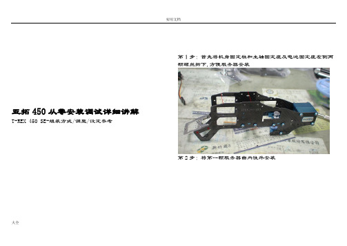
亚拓450从零安装调试详细讲解T-REX 450 SE-组装方式/调整/设定参考第1步:首先将机身固定柱和主轴固定座及电池固定座左侧两颗螺丝拆下,方便服务器安装第2步:将第一颗服务器由内往外安装大全大全第3步:同样的由内往外安装第二颗服务器,并将讯号线排列整齐用速线带固定,切记(1.速线带头在机身内侧2.在固定于册版的地方用透明胶带包覆两圈,防止组装时讯号线破损)第4步:将伺服机讯号线由内侧版经沟槽穿往机身外侧第5步,将服务器的讯号线整理后,再用蛇管包覆大全第6步:将机身固定柱和主轴固定座及电池固定座左侧两颗螺丝装回原来位置记得要上螺丝胶喔第7步:将中间的侧版固定柱套入,并对准螺丝孔.将马达固定座装上下侧版第8步:1.利用马达固定座将上.下侧版组合2.将中侧版固定柱锁上螺丝大全第9步:将服务器讯号线穿过上.下侧版并将左侧三颗螺丝锁上第10步:右侧版先锁上1的螺丝,其它两颗先不锁第11步:将所需的马达同齿固定后,在将马达固定在马达坐上第12步:将马达线穿过机身底板和组装好的脚架,并将脚架固定第13步:将皮带穿过尾管(注意皮带的方向性)并将尾服务器座大全套入尾管,然后跟机身组合,并将垂直/水平/支撑架装上,调整皮带的松紧度后上紧尾管固定座的螺丝第14步:金属尾传动轮座组固定前,需确认与尾管固定座呈平行状态第15步:陀螺仪的整线后用蛇管包覆大全第16步:将陀螺仪用双面胶固定在尾管固定座上后,将包覆好的讯号线穿过上.下侧版后再将右侧版的两颗螺丝上紧(陀螺仪安装在尾固定座的下方,以防炸机时被副翼打到)第17步:先抓出尾服务器的中点,并将球头固定在服务器的摆臂上(上下两个圈是行程终点),并将服务器固定在尾伺服座上第18步:装好尾服务器时,套上连杆后,注意,这是重点 1,尾舵控制组需在尾主轴中央2.调整尾服务器座让连杆跟尾管平行3.尾服务器摆臂球头需在中点4. 尾连杆和尾管尽量跟尾管呈平行 以上确定后在固定尾伺服座螺丝大全第19步:1.将主轴上的连杆按说明书上的长度组装,并套上摆臂平衡杆先量好两边相等长度后套入平衡杆重垂在装上平衡翼2.将主轴和机身组合第20步:组合好后请注意大齿盘于机身的间隙,不能摩擦到机身或尾传动轮第21步:调整马达铜齿的高度并将铜齿固定螺丝上紧,调整马大全达与大齿盘的间隙后再将马达固定螺丝上紧第22步:1.用2mm 钻尾将欲锁球头的摆臂扩孔2.将球头利用螺母固定在摆臂上3.将多余的摆臂去掉.以免摆动时干涉4.将服务器连杆依说明书长度组装好第23步:将组装好的摆臂套上服务器,先不上服务器螺丝,以便调整时需拆下,此时连杆都是呈垂直状态第24步:接收的整理大全1.用热缩套管或由机的油管将接收线的前端包覆,以防接收线和侧版接触而出现干扰现象,相信很多人有这个经验2.用1mm 的泡棉将接受包覆并用透明胶带在包覆,以防日久泡棉脱落,这可以防止摔机后的碰撞以以多一层的防干扰的作用第25步:1.用双面胶将接收固定在底板2.将讯号线接上接收第26步:1.用打火机熏烤将热缩套管定型你要的角度2.在用热缩套管将整理的接收线固定在线管上第27步:将电子变速器的讯号线穿过脚架和底板之间并接上接大全收(马达线先不要接,以便遥控器设定和调机)------------------以上是机械及电子部件的安装---------------第28步:控的设置,打开遥控器进入SWASHTYP ,打开选项选择120度第29步:接上电池,将摆臂尽量以90度脚平行装上,并推油门游戏杆以确认伺服机的方向正确,如有反向,可进入REV.SW 个别调整正确方向大全第30步:如摆臂有微些差距,可进入sub trim 个别微调至所有摆臂至平行,调整好后记得看看十字盘是否平行,如没平行,调整十字盘连杆使起平行既可第31步:接下来先将主旋翼做好静态平衡后,装上直升机,并将服务器螺丝锁上第32步:进入遥控器选项里的PIT.CURV.1.并将油门游戏杆推至中点2.在NORM设定页面3.将EXP显至ON的位置,这可以自行调整曲线较为顺畅第33步:已有贴配重贴纸的桨为主1.将螺距规套上,并以螺距规的上沿跟平衡杆呈平行2.此时应为0度,如没0度,可依差距大小调整连杆使其成为0度第34步:将油门游戏杆推至最高并记下为+11度大全第35步:将油门推至最低,并记下为-11度,对高手来说,这个螺距应该是可以的第36步:如想减少螺距行程,可进入swash mix的PIT降低%数(5%为一度左右),所以我降了10%,此时螺距为(-9 0 +9)这应该适合一般飞友大全大全第37步:接下来是在进入PIT. CURV 设定NORM 的螺距,第一点位置设定为-2度,此时数据为38%第38步:接着将油门游戏杆推至中点3的位置(约是停悬点),为+5度,此时该点数据为75%大全第39步:在来是将刚刚设定的38%和75%以及最高的100%三点中的曲线,设定调整一条顺畅的拋物线,这样一来,在操控的过程会顺畅许多,不会又高高低低的情况发生第40步:接下来进入THRO CHRV 的NORM 页面设定油门曲线,首先在第3点(中点)位置将数据设定为68%第41步:接下来是一般人常遇到也是最让你头痛的尾巴设定,如果你刚刚再组装的时候有按照图示安装,基本上尾服务器的中立点已经抓好了,所以不会有偏的问题发生,只要了解陀螺一的功能和调整就可以了,A.接上电源如果灯恒亮,就表示锁头模式,1数字/模拟的切换开关,如果你用的尾舵机不是数码的,必须将开关切至OFF 的位置,如果是数码舵机择切换至ON 的位置2.陀螺仪反向开关3.延迟开关,如果是数字服务器这个开关可以不用管他,在O 的位置.如是用模拟服务器,感度以将很低仍有追踪现象,可调整此开关改善4.陀螺仪行程开关,如行程太大会产生操控尾舵时,定点会有抖几下的情况,可降低此行程来改善第42步:确认方向舵方向,通常尾舵控制组跟方向游戏杆是反方向移动,这才是正确的第43步:确认好后接下来进入遥控器GYRO SENS AUTO页面设定陀螺仪感度POS.0为一般飞行感度设定POS.1为3D飞行感度设定设定好感度后不要忘了也要进入由上角将POS.0和POS.1个别设定好,如此一来,感度才会跟着你切换的飞行模式而改变大全大全第44步:设定好后,将电子变速器和马达的线依颜色接上,并将固定第45步:设定的过程中,有些飞友会利用这个页面调整服务器的行程,来达到所需的螺距,这是错误的,就算调整好了,+-数据不相等,这会产生打动作时,左右的速度不均现象大全第46步:还有一种错误的调整螺距的方式,如图示,降低/提高螺距曲线的%数来迎合所需的螺距,这也会让你在操控时,游戏杆上下不均匀,也缩短了螺距变化的空间,所谓一步错步步错!第47步:接下来是调整双桨,以量螺距的桨为机准桨(贴配重贴纸的桨),此桨不动视另一只桨高低作调整就可以了,完工!资料来源:亚拓台湾官网论坛大全。
FastMig Pulse 350 450 产品说明书

Work Pack
15 welding programs
Aluminium Pack Steel Pack
12 welding programs 12 welding programs
Stainless Steel Pack Work Pack + WiseFusion Aluminium Pack + WiseFusion
12 welding programs 15 welding programs 12 welding programs
Steel Pack + WiseFusion Stainless Steel Pack + WiseFusion
12 welding programs 12 welding programs
Project Pack offers the ultimate flexibility, suiting customers with very specific project requirements. With Project Pack you can select your own welding software profile from the DataStore, which is Kemppi’s online webstore.
For full package details and software options visit Kemppi DataStore at
亚拓450螺距和油门曲线设定体会
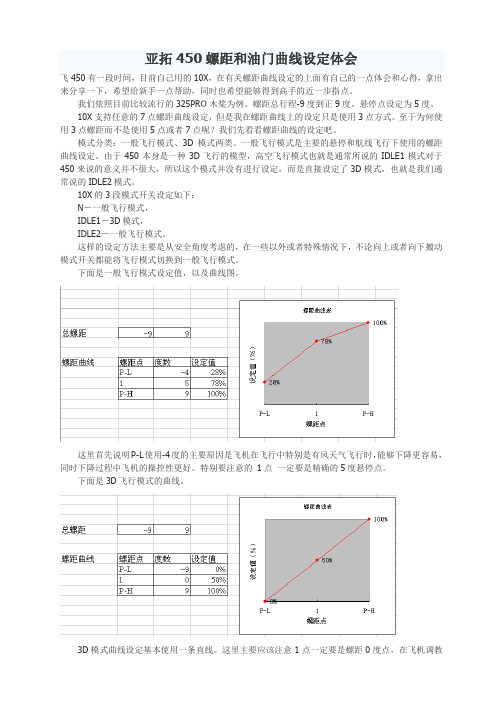
亚拓450螺距和油门曲线设定体会飞450有一段时间,目前自己用的10X,在有关螺距曲线设定的上面有自己的一点体会和心得,拿出来分享一下,希望给新手一点帮助,同时也希望能够得到高手的近一步指点。
我们依照目前比较流行的325PRO木桨为例。
螺距总行程-9度到正9度。
悬停点设定为5度。
10X支持任意的7点螺距曲线设定,但是我在螺距曲线上的设定只是使用3点方式。
至于为何使用3点螺距而不是使用5点或者7点呢?我们先看看螺距曲线的设定吧。
模式分类:一般飞行模式、3D模式两类。
一般飞行模式是主要的悬停和航线飞行下使用的螺距曲线设定。
由于450本身是一种3D飞行的模型,高空飞行模式也就是通常所说的IDLE1模式对于450来说的意义并不很大,所以这个模式并没有进行设定,而是直接设定了3D模式,也就是我们通常说的IDLE2模式。
10X的3段模式开关设定如下:N-一般飞行模式,IDLE1-3D模式,IDLE2-一般飞行模式。
这样的设定方法主要是从安全角度考虑的,在一些以外或者特殊情况下,不论向上或者向下搬动模式开关都能将飞行模式切换到一般飞行模式。
下面是一般飞行模式设定值,以及曲线图。
这里首先说明P-L使用-4度的主要原因是飞机在飞行中特别是有风天气飞行时,能够下降更容易,同时下降过程中飞机的操控性更好。
特别要注意的1点一定要是精确的5度悬停点。
下面是3D飞行模式的曲线。
3D模式曲线设定基本使用一条直线。
这里主要应该注意1点一定要是螺距0度点,在飞机调教的时候首先要注意0度点的调整。
其次,尽量取保正负螺距值的相同。
这个是熄火模式的螺距曲线,为了在熄火降落的过程中保持主旋翼的足够转速,这里主要是定义P-L点的螺距为-7度,P-H为最大螺距值,然后设定出一条直线。
如果遥控中有螺距EXP设定项目,尽量不要打开。
保证螺距曲线为直线。
看过我的螺距曲线设定后,我来解释一下为什么使用3点曲线设定,而不是更多的5点和7点。
螺距的直线设定实际上在操控的时候更容易把握螺距的变化点,特别在一般飞行模式下这样设定实际上是在为以后的3D飞行打基础。
Leica Aperio GT 450 产品说明书

Aperio GT 450SpecificationsMAN-0393, Revision H | March 2022Aperio GT 450 SpecificationsThis manual applies to Aperio GT 450 Controller, Aperio GT 450 Console, and Aperio GT 450 SAM versions 1.1and laterCopyright NoticeÌCopyright © 2019-2022 Leica Biosystems Imaging, Inc. All Rights Reserved. LEICA and the Leica logo are registered trademarks of Leica Microsystems IR GmbH. Aperio, GT, and GT 450 are trademarks of Leica Biosystems Imaging, Inc. in the USA and optionally in other countries. Other logos, products, and/or company names might be trademarks of their respective owners.ÌThis product is protected by registered patents. For a list of patents, contact Leica Biosystems.Customer ResourcesÌFor the latest information on Leica Biosystems Aperio products and services, please visit /Aperio.Contact Information – Leica Biosystems Imaging, Inc.23GT450, 23GT450SAMAperio GT 450 Specifications, Revision H © Leica Biosystems Imaging, Inc. 2022 2ContentsNotices (4)Revision Record (4)Cautions and Notes (4)Introduction (6)Aperio GT 450 Scanner Specifications (6)General Scanner Specifications (6)Aperio GT 450 Features (7)Performance Specifications (7)Power Specifications (8)Slides and Racks Specifications (8)Environmental Specifications (9)Network Specifications (10)Aperio GT 450 Scanner Administration Manager (SAM) Server Specifications (10)Viewing Station Specifications (11)Client Workstation (11)Monitor (11)Aperio GT 450 Compliance Specifications (12)Aperio GT 450 Network Configuration (13)Aperio GT 450 Specifications, Revision H © Leica Biosystems Imaging, Inc. 20223NoticesNoticesRevision RecordCautions and Notes`Serious Incidents Reporting - Any serious incident that has occurred in relation to the Aperio GT 450 shall bereported to the manufacturer and the competent authority of the member state in which the user and/or the patient is established.`Specifications and Performance - For device specifications and information on performance characteristics,refer to this document, Aperio GT 450 Specifications.`Installation - Aperio GT 450 must be installed by a trained Leica Biosystems Technical Services representative.`Repair - Repairs may be done only by a trained Leica Biosystems Technical Services representative. After repairsare done, ask the Leica Biosystems technician to perform operation checks to determine the product is in goodoperating condition.`Accessories - For information on using Aperio GT 450 with third-party accessories such as a LaboratoryInformation System (LIS) not provided by Leica Biosystems, contact your Leica Biosystems Technical Servicesrepresentative.Aperio GT 450 Specifications, Revision H © Leica Biosystems Imaging, Inc. 2022 4Notices `Quality Control -For information on image quality checks, see the Aperio GT 450 User’s Guide.`Maintenance and Troubleshooting -For information on maintenance and troubleshooting problems, see theAperio GT 450 User’s Guide.`Cybersecurity - Be aware that workstations are susceptible to malware, viruses, data corruption, and privacybreaches. Work with your IT administrators to protect workstations by following your institution’s password and security policies. For Aperio recommendations on protecting your workstations and servers, see the documentAperio GT 450 IT Manager and Lab Administrator Guide.To protect workstations from malware intrusion, use caution when inserting USB drives and other removabledevices. Consider disabling USB ports that are not in use. If you plug in a USB drive or other removable device, you should scan the devices with an anti-malware utility.If a suspected Aperio GT 450 cybersecurity vulnerability or incident is detected, contact Leica Biosystems Technical Services for assistance.`Training - This manual is not a substitute for the detailed operator training provided by Leica Biosystems or forother advanced instruction.`Safety - Safety protection may be impaired if this device is used in a manner not specified by the manufacturer.For additional information on this product, including intended use and symbols glossary, please refer to theprimary instructions for use, Aperio GT 450 User’s Guide.Aperio GT 450 Specifications, Revision H © Leica Biosystems Imaging, Inc. 20225IntroductionThis document lists the latest specification information for the Aperio GT 450 scanner. For details on using this device, refer to the Aperio GT 450 User’s Guide.The Aperio GT 450 is a high performance, brightfield whole slide scanner that includes continuous loading with 450 slide-capacity across 15 racks, priority rack scanning, automated image quality check and a scan speed of ~32 seconds at 40x scanning magnification for a 15 mm x 15 mm area.This system is intended for use by trained histotechnicians, IT professionals, and pathologists. Ensure you follow appropriate good laboratory practices and the policies and procedures required by your institution for slide preparation, processing, storage, and disposal. Use this equipment only for this purpose and in the manner described in the Aperio GT 450 User’s .GuideThe following sections contain specifications for the Aperio GT 450.Routine setup and functional verification is required by a Leica Biosystems Service representative after shipping.General Scanner SpecificationsAperio GT 450 Specifications, Revision H © Leica Biosystems Imaging, Inc. 2022 6Aperio GT 450 FeaturesPerformance SpecificationsAperio GT 450 Specifications, Revision H © Leica Biosystems Imaging, Inc. 20227Power SpecificationsInstrument: 24V 10.5A+*****************Slides and Racks SpecificationsAperio GT 450 Specifications, Revision H © Leica Biosystems Imaging, Inc. 2022 8Environmental SpecificationsAperio GT 450 Specifications, Revision H © Leica Biosystems Imaging, Inc. 20229Network SpecificationsAperio GT 450 Scanner Administration Manager (SAM) Server Specifications i The Scanner Administration Manager (SAM) supports up to 4 Aperio GT 450 scanners. Multiple SAMservers can be added to your network.For information on network configuration and data flow in the Aperio GT 450 system, refer to “Aperio GT 450 Network Configuration” on page 13 and the Aperio GT 450 IT Manager and Lab Administrator Guide.Aperio GT 450 Specifications, Revision H © Leica Biosystems Imaging, Inc. 2022 10Viewing Station SpecificationsThe viewing station (part number 23VS101) uses calibrated monitor(s) and a workstation with Aperio ImageScope version12.4 or higher.A viewing station is optional and is not included in the Aperio GT 450 base product. The following specifications are required for optimal image viewing.Client WorkstationMonitorFor best image quality during viewing, a calibrated monitor must be used.The monitor(s) included in the Aperio Viewing Station are calibrated to a Leica internal specification which is specific for stain colors and optimized for digital slide viewing by pathologists.However, if you purchase your own monitor, calibrating to sRGB standards will give an acceptable viewing experience.Aperio GT 450 Specifications, Revision H © Leica Biosystems Imaging, Inc. 202211Aperio GT 450 Compliance SpecificationsThis device complies with Part 15 of the FCC rules. Operation is subject to the following two conditions: (1) This device may not cause harmful interference and (2) this device must accept any interference received, including interference that may cause undesired operation.This device has been evaluated against and conforms to the following standards:Aperio GT 450 Specifications, Revision H © Leica Biosystems Imaging, Inc. 2022 12Aperio GT 450 Specifications, Revision H © Leica Biosystems Imaging, Inc. 202213Aperio GT 450 Network ConfigurationThis section contains information on how the Aperio GT 450 fits into your network for optimized scanning and image viewing performance. For more details on this topic, see the Aperio GT 450 IT Manager and Lab Administrator Guide .Confi g Data Port 44386Image Data TCP 2762ImageMetadata Port 44386Aperio GT 450 ScannerEvent Data Ports 6662, 6663SAM DataServerMirthDICOM ConverterSQL ServerDatabaseSAM Server File SystemLog DataEventsEventsConfi g DataSecured Port 443SAM Web PageImage MetadataPort 44386Image Data UDP 137, 138TCP 139, 445Aperio eSlide Manager DataServerImage Server File SystemDSR ServerSAM ServerTime Syn c hronization Port 123Aperio GT 450 Specifications, Revision H © Leica Biosystems Imaging, Inc. 202214Aperio GT 450 Specifications, Revision H © Leica Biosystems Imaging, Inc. 202215/Aperio。
leica Aperio GT 450 IT 管理員與實驗室系統管理員指南说明书
Aperio GT 450IT 管理員與 實驗室系統管理員指南MAN-0394-zh-CHT ,修訂版 D | 2021 年 1 月 13日僅供研究使用。
不得用於診斷程序。
Aperio GT 450 IT 管理員與實驗室系統管理員指南版權聲明Ì© 2019-2021 Leica Biosystems Imaging, Inc. 版權所有,保留所有權利。
LEICA 和 Leica 標誌是 Leica Microsystems IR GmbH 的註冊商標。
Aperio 是 Leica Biosystems 公司集團在美國及其他國家(選擇性)的商標。
其他標誌、產品和/或公司名稱可能為其各自所有人之商標。
Ì本產品受註冊專利保障。
如需專利列表,請聯絡 Leica Biosystems。
客戶資源Ì如需 Leica Biosystems Aperio 產品及服務的最新資訊,請造訪 /Aperio。
免責聲明Ì本手冊不能取代 Leica Biosystems Imaging 提供的詳細操作員培訓或其他進階的指示。
若發生任何儀器故障,應立即聯絡 LeicaBiosystems Imaging 駐場代表尋求協助。
硬體安裝應僅由獲得認證的 Leica Biosystems Imaging 服務工程師進行。
2Aperio GT 450 IT 管理員與實驗室系統管理員指南,修訂版 D © Leica Biosystems Imaging, Inc. 2021客戶服務部聯絡資訊請聯絡您所在國家的辦公室尋求技術協助。
澳洲:96 Ricketts RoadMount Waverly, VIC 3149AUSTRALIA電話:1800 625 286(免付費)週一至週五上午 8 時 30 分至下午 5 時(澳洲東部時間)。
電子郵件:***********************************奧地利:Leica Biosystems Nussloch GmbHTechnical Assistance CenterHeidelberger Strasse 17Nussloch 69226GERMANY電話:0080052700527(免付費)國內電話:+43 1 486 80 50 50電子郵件:******************************比利時:電話:0080052700527(免付費)國內電話:+32 2 790 98 50電子郵件:******************************加拿大:電話:+1 844 534 2262(免付費)國際直撥電話:+1 760 539 1150電子郵件:********************************中國:中國上海市黃浦區打浦橋徐家匯路 610 號日月光中心廣場 17 樓郵遞區號:200025電話: +86 4008208932傳真:+86 21 6384 1389電子郵件:*********************************遠端照護電子郵件:*****************************丹麥:電話:0080052700527(免付費)國內電話:+45 44 54 01 01電子郵件:******************************德國:Leica Biosystems Nussloch GmbH Technical Assistance Center Heidelberger Strasse 17Nussloch 69226GERMANY電話:0080052700527(免付費)國內電話:+49 6441 29 4555電子郵件:******************************愛爾蘭:電話:0080052700527(免付費)國內電話:+44 1908 577 650電子郵件:******************************西班牙:電話:0080052700527(免付費)國內電話:+34 902 119 094電子郵件:*********************************法國:電話:0080052700527(免付費)國內電話:+33 811 000 664電子郵件:******************************義大利:電話:0080052700527(免付費)國內電話:+39 0257 486 509電子郵件:*********************************日本:1-29-9 Takadannobaba, Sinjuku-kuTokyo 169-0075JAPAN荷蘭:電話:0080052700527(免付費)國內電話:+31 70 413 21 00電子郵件:******************************Aperio GT 450 IT 管理員與實驗室系統管理員指南,修訂版 D © Leica Biosystems Imaging, Inc. 20213紐西蘭:96 Ricketts RoadMount Waverly, VIC 3149AUSTRALIA電話: 0800 400 589(免付費)週一至週五上午 8 時 30 分至下午 5 時(澳洲東部時間)。
ALIGN T-REX 450L DOMINATOR组装介绍
上海FUNFLY回来,拿到了亚拓最新款的450L,开箱贴前面有模友发了不少了,这里就不再啰嗦了,直接装机,并同大家分享一下装机过程。
本人水平有限,如有错误,欢迎大家指正。
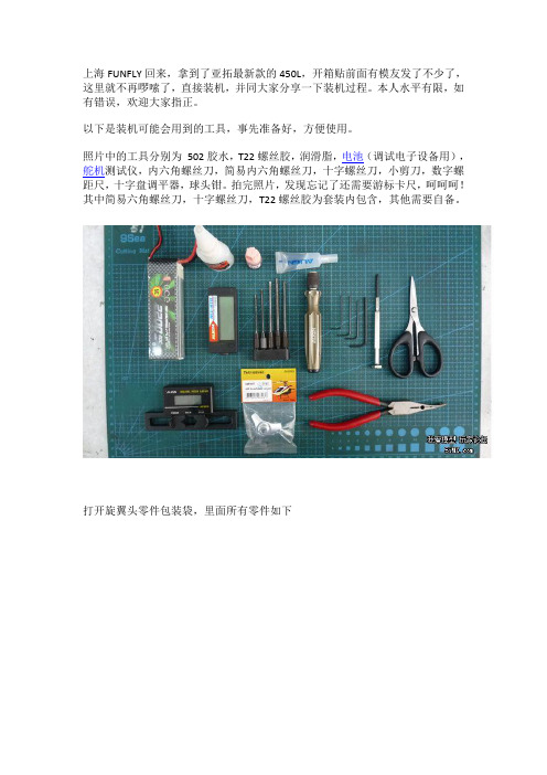
以下是装机可能会用到的工具,事先准备好,方便使用。
照片中的工具分别为502胶水,T22螺丝胶,润滑脂,电池(调试电子设备用),舵机测试仪,内六角螺丝刀,简易内六角螺丝刀,十字螺丝刀,小剪刀,数字螺距尺,十字盘调平器,球头钳。
拍完照片,发现忘记了还需要游标卡尺,呵呵呵!其中简易六角螺丝刀,十字螺丝刀,T22螺丝胶为套装内包含,其他需要自备。
打开旋翼头零件包装袋,里面所有零件如下拆散全部零件,照片中为单边桨夹及其零件,为方便大家更换零件,特地标注了一下配件编号,后面的装机照片中,标注了编号的零件都是同现在的450通用的。
没有标注的为450L的专用零件。
这里特别说明一下,亚拓原厂预装的零件全部为假组合,需要自行拆散重新安装打胶将横轴垫圈装入中联将润滑脂均匀的涂抹在止推轴承上组合好止推轴承,两边的垫片上分别标记有 IN和OUT,其中标记IN的那边朝向桨夹内侧安装横轴螺丝套上垫片,打一点T22,注意不要太多,螺丝前面3-4个丝口涂上螺丝胶即可。
新款的横轴螺丝为M2.5*6mm,安装时需要使用2.0mm的螺丝刀将滚珠轴承,止推轴承垫片,止推轴承,依此穿入横轴,并拧入横轴螺丝搞定把安装好轴承的横轴穿入大桨夹,不要遗漏大桨夹和中联之间的那个铝套将横轴穿入中联,在横轴表面涂抹适当润滑油将另一边的桨夹,按照上面的顺序,安装好轴承,并穿入横轴,拧入横轴螺丝。
使用两把螺丝刀,锁紧横轴螺丝将十字盘上的球头拆下,重新打上螺丝胶安装好。
450L的十字盘,主体和450DFC的相同,但是CCPM的3个球头长度不同于450DFC斜盘将DFC连杆打上螺丝胶,拧入大桨夹连杆,请注意DFC连杆的正反,不要装错把DFC球头扣拧入DFC连杆,注意球头扣比较紧,需要慢慢拧入。
阿图祖调试手册
GE Infrastructure
Water & Process Technologies
Aperio GT 450 DX 产品说明书.pdf_1718564625.3389082

Aperio GT 450 DX SpecificationsMAN-0479, Revision A | April 2022Aperio GT 450 DX SpecificationsThis manual applies to Aperio GT 450 DX Controller, Aperio GT 450 DX Console, and Aperio GT 450 DX SAM DXversions 1.1 and laterCopyright NoticeÌCopyright © 2022 Leica Biosystems Imaging, Inc. All Rights Reserved. LEICA and the Leica logo are registered trademarks of Leica Microsystems IR GmbH. Aperio, GT, and GT 450 are trademarks of Leica Biosystems Imaging, Inc. in the USA and optionally in other countries. Other logos, products, and/or company names might be trademarks of their respective owners.ÌThis product is protected by registered patents. For a list of patents, contact Leica Biosystems.Customer ResourcesÌFor the latest information on Leica Biosystems Aperio products and services, please visit /Aperio.Contact Information – Leica Biosystems Imaging, Inc.00815477020297, 0081547702038923GT450DXIVD, 23SAMSWDXIVDAperio GT 450 DX Specifications, Revision A © Leica Biosystems Imaging, Inc. 2022 2ContentsNotices (4)Revision Record (4)Cautions and Notes (4)Introduction (5)Aperio GT 450 DX Components (5)Aperio GT 450 DX Scanner Specifications (6)General Scanner Specifications (6)Performance Specifications (7)Power Specifications (7)Slides and Rack Specifications (8)Environmental Specifications (9)Network Specifications (9)Scanner Administration Manager DX (SAM DX) Server Minimum Specifications (9)Aperio GT 450 DX Compliance Specifications (11)Aperio GT 450 DX Recommended Network Configuration (12)Aperio GT 450 DX Specifications, Revision A © Leica Biosystems Imaging, Inc. 20223NoticesNoticesRevision RecordCautions and Notes`Serious Incidents Reporting - Any serious incident that has occurred in relation to the Aperio GT 450 DX shall be reported to the manufacturer and the competent authority of the member state in which the user and/or the patient is established.`Specifications and Performance - For device specifications and information on performance characteristics, refer tothis document, Aperio GT 450 DX Specifications.`Installation - Aperio GT 450 DX must be installed by a trained Leica Biosystems Technical Services representative.`Repair - Repairs may be done only by a trained Leica Biosystems Technical Services representative. After repairsare done, ask the Leica Biosystems technician to perform operation checks to determine the product is in goodoperating condition.`Accessories - For information on using Aperio GT 450 DX with third-party accessories such as a Laboratory Information System (LIS) not provided by Leica Biosystems, contact your Leica Biosystems Technical Servicesrepresentative.`Quality Control -For information on image quality checks, see the Aperio GT 450 DX User’s Guide.`Maintenance and Troubleshooting -For information on maintenance and troubleshooting problems, see the AperioGT 450 DX User’s Guide.`Cybersecurity - Be aware that workstations are susceptible to malware, viruses, data corruption, and privacybreaches. Work with your IT administrators to protect workstations by following your institution’s password andsecurity policies. For Aperio recommendations on protecting your workstations and servers, see the documentAperio GT 450 DX IT Manager and Lab Administrator Guide.If a suspected Aperio GT 450 DX cybersecurity vulnerability or incident is detected, contact Leica BiosystemsTechnical Services for assistance.`Training - This manual is not a substitute for the detailed operator training provided by Leica Biosystems or for otheradvanced instruction.`Safety - Safety protection may be impaired if this device is used in a manner not specified by the manufacturer.i For additional information on this product, including intended use and symbols glossary, please refer to the primaryinstructions for use, Aperio GT 450 DX User’s Guide.Aperio GT 450 DX Specifications, Revision A © Leica Biosystems Imaging, Inc. 2022 4IntroductionThe Aperio GT 450 DX is a high performance, brightfield whole slide scanner that includes continuous loading with 450 slide-capacity across 15 racks, priority rack scanning, automated image quality check and a scan speed of ~32 seconds at 40x scanning magnification for a 15 mm x 15 mm area.The Aperio GT 450 DX is intended for use by trained clinical pathology histotechnicians, while the Aperio GT 450 SAM DX software is intended for use by IT professionals and laboratory administrators.The Aperio GT 450 DX is intended for use in medium- to high-volume clinical pathology laboratories that support the pathology services of a hospital, reference laboratory or other clinical facility.It is the responsibility of a qualified pathologist to employ appropriate procedures and safeguards to assure the validity of the interpretation of images obtained using the Aperio GT 450 DX. Pathologists should exercise professional judgment in each clinical situation and examine the glass slides by conventional microscopy if there is doubt about the ability to accurately render an interpretation using this device alone.Ensure you follow appropriate good laboratory practices and the policies and procedures required by your institution for slide preparation, processing, storage, and disposal. Use this equipment only for this purpose and in the manner described in the Aperio GT 450 DX User’s Guide.See the manuals for your digital slide viewer for specifications for monitors and workstations.Aperio GT 450 DX ComponentsThe Aperio GT 450 DX requires these components for administering the scanner:Aperio GT 450 DX Specifications, Revision A © Leica Biosystems Imaging, Inc. 20225SpecificationsAperio GT 450 DX Scanner SpecificationsThe following sections contain specifications for the Aperio GT 450 DX.General Scanner SpecificationsAperio GT 450 DX FeaturesFeature1. To use the DICOM file format, this feature must be enabled for your scanner on SAM DX. See Aperio GT 450 DX IT Manager and LabAdministrator Guide for details. Also, your IT environment must meet the requirements detailed in the Aperio DICOM Conformance Statement.Aperio GT 450 DX Specifications, Revision A © Leica Biosystems Imaging, Inc. 2022 6SpecificationsPerformance SpecificationsPower SpecificationsInstrument: 24V 10.5A.+*****************Aperio GT 450 DX Specifications, Revision A © Leica Biosystems Imaging, Inc. 20227SpecificationsSlides and Rack SpecificationsAperio GT 450 DX Specifications, Revision A © Leica Biosystems Imaging, Inc. 2022 8Specifications Environmental SpecificationsNetwork SpecificationsRoutine setup and functional verification is required by a Leica Biosystems Service representative after shipping. Scanner Administration Manager DX (SAM DX) Server Minimum Specifications This section provides the minimum specifications for the server that hosts the SAM DX application software. Your SAM DX server must meet or exceed these requirements. Leica Biosystems does not recommend using virtualized (VM) SAM DX server configurations.Aperio GT 450 DX Specifications, Revision A © Leica Biosystems Imaging, Inc. 20229SpecificationsThe Scanner Administration Manager DX (SAM DX) supports up to 4 Aperio GT 450 DX scanners. Multiple SAM DXservers can be added to your network.For information on recommended network configuration and data flow for the Aperio GT 450 DX, refer to”Aperio GT 450 DX.Recommended Network Configuration” on page 12 and the Aperio GT 450 DX IT Manager and Lab Administrator GuideAperio GT 450 DX Specifications, Revision A © Leica Biosystems Imaging, Inc. 2022 10Specifications Aperio GT 450 DX Compliance SpecificationsThis device complies with Part 15 of the FCC rules. Operation is subject to the following two conditions: (1) This device may not cause harmful interference and (2) this device must accept any interference received, including interference that may cause undesired operation. This device has been evaluated against and conforms to the following standards:Aperio GT 450 DX Specifications, Revision A © Leica Biosystems Imaging, Inc. 202211Aperio GT 450 DX Specifications, Revision A © Leica Biosystems Imaging, Inc. 202212SpecificationsAperio GT 450 DX Recommended Network ConfigurationThis section describes the recommended way to connect your Aperio GT 450 DX in your IT environment for optimal performance. For more details on this topic, see the Aperio GT 450 DX IT Manager and Lab Administrator Guide .IT network failure may lead to delay in diagnosis/prognosis until the network is restored.Confi g Data Port 44386TLSImage Data TCP 2762TLSImage MetadataPort 44386TLS Aperio GT 450 DX ScannerEvent Data Ports 6662, 6663No sensitive dataSAM DataServerMirthDICOM ConverterSQL ServerDatabaseSAM Server File SystemLog DataEventsEventsConfi g DataSecured Port 443SAM Web PageImage MetadataPort 44386TLSImage Data UDP 137, 138TCP 139, 445SMB3Image and Data Management SystemImage Server File SystemDSR ServerSAM ServerTime Syn c hronization Port 123Viewing stationViewing stationSpecificationsAperio GT 450 DX Specifications, Revision A © Leica Biosystems Imaging, Inc. 202213/Aperio。
Aperio GT 450快速参考指南说明书
Aperio GT 450 Quick Reference GuideAperio GT 450 Quick Reference GuideCopyright NoticeÌCopyright © 2019 Leica Biosystems Imaging, Inc. All Rights Reserved. LEICA and the Leica logo are registered trademarks of Leica Microsystems IR GmbH. ÌAperio is a trademark of the Leica Biosystems group of companies in the USA and optionally in other countries. Other logos, product and/or company names might be trademarks of their respective owners.Contact Information – Leica Biosystems Imaging, Inc.Aperio GT 450 Quick Reference Guide, Revision A1. INTRODUCTION (5)Help Videos (5)User Guides (5)Scanner Overview (6)Touchscreen Interface Overview (7)Scanning Workflow (8)Carousel Rotation (9)Key Concepts (10)Icon Glossary (11)2. SLIDE PREPARATION CHECKLISTS (12)Slides (12)Coverslips (12)Slide Labels (12)Barcodes (12)3. SCAN SLIDES (13)Load Racks in the Carousel (14)Unload Racks from the Carousel (15)Priority Scanning (16)Scan Status (17)Scan Statistics (18)Rack View (19)Slide View (20)Rack Order (20)Rack Warnings (21)4. MAINTENANCE (22)Maintenance Checklists (22)Daily (recommended) (22)Six Month (22)Yearly (22)Restart the Scanner (23)Shut Down the Scanner (23)ContentsAperio GT 450 Quick Reference Guide, Revision A5. TROUBLESHOOTING (24)Additional Resources (24)Serial Number and Firmware Version (24)Open and Close the Scanner Cover (25)Return Pusher to Safe Position (26)Safe Restart After an Error (27)Errors and Solutions (28)Broken Slides Inside the Scanner (41)6. INDEX (42)Aperio GT 450 Quick Reference Guide, Revision AIntroductionThis guide provides basic steps for using the Aperio GT 450 digital slide scanner. See below for additional resources. Please watch the videos (accessible from the touchscreen interface) before working with the scanner.Aperio GT 450 Quick Reference Guide, Revision A Scanner OverviewAperio GT 450 Front Aperio GT 450 BackAperio GT 450 Quick Reference Guide, Revision A Touchscreen Interface OverviewThe example below shows the Home screen.Rack orderCarousel and rack statusSelected rackRack actionsRack rotated automaticallyScanning starts Scan and Image QC complete Slides loadedAperio GT 450 Quick Reference Guide, Revision A Carousel RotationWARNING: Keep hands away from the carousel and pinch point areas whenthe carousel is rotating.AVERTISSEMENT: Garder les mains éloignées du carrousel et des zones depoints de prise quand le carrousel est en rotation.If an object breaks thelight curtain:yy the carousel does notrotateyy the 10-second timerstarts againAn infrared safety lightcurtain detects objects inthe loading area:Safety light curtainAperio GT 450 Quick Reference Guide, Revision A Key ConceptsIntroduction | 11Icon GlossaryThe following icons appear on the touchscreen interface.Slide Preparation ChecklistsScan SlidesLoad Racks in the CarouselSlides are scanned in the order loaded.When the rack is fully inserted, there is a “click” sound, and the rack position on the Home screen turns light blue.Continue loading racks as needed or until you fill the front-six rack slots.Wait for the carousel to rotate more empty rack slots to the loading area.14 | Scan SlidesUnload Racks from the CarouselTo unload a rack that is not in the loading area: Tap the rack position.Priority ScanningScan StatusScan StatisticsTo view scan statistics, tap Stats. To change the time frame of the statistics, tap the buttons above the graph.18 | Scan SlidesScan Slides | 19Rack View1. Tap the Rack Viewicon to show the scan status for each slide in the rack.Slide status colors correspond to the Legend:Tap 20 | Scan SlidesRack WarningsOrange warningScan Slides | 21MaintenanceMaintenance ChecklistsTo maximize scanner performance and image quality, follow this recommended maintenance schedule.Daily (recommended)ÌRestart the scanner. (Seepage 23.)Six MonthÌClean the objective and KoehlerÌClean the stage slide trayÌClean the carouselÌClean the slide racksÌClean the fan filterÌClean the touchscreenÌClean the scanner coverThe Six Month Maintenance procedures areprovided in the Aperio GT 450 User’s Guide“Maintenance” chapter.YearlyÌLeica Biosystems TechnicalServices annual maintenancevisit. (Contact Leica Biosystemsto schedule. See page 2 forcontact details.)1. Ensure all racks are unloaded, no slides are scanning, andTroubleshootingThis section provides some common troubleshooting issues and solutions. For a comprehensive list of troubleshooting issues, see the Aperio GT 450 User’s Guide.Additional Resources`Aperio GT 450 User’s Guide contains a comprehensive “Troubleshooting” chapter.Ì`The Maintenance Videos available from the touchscreen interface include common troubleshooting procedures. TapÌMaintenance, then tap Maintenance Videos.Serial Number and Firmware VersionYou need the serial number and current software version if you call Leica Biosystems Technical Support.`Tap Maintenance on the touchscreen to view the serial number, firmware version, and other system information.ÌÌ`The serial number and firmware version are also available from the Aperio GT 450 SAM Application Software. See the Aperio GT 450 IT Manager and Lab Administrator Guide.Open and Close the Scanner CoverYou need to open the cover to perform certain maintenance and troubleshooting tasks. For detailed instructions on how to open and close the scanner, see the user’s guide for the scanner.25 | TroubleshootingReturn Pusher to Safe PositionFollow these steps when the troubleshooting procedure asks you to return the pusher to the safe position.1. Align the pusher teeth with the slide stage groves:2. Slide the stage to the rear of the scanner:4. Slide the pusher to the front of the scanner as shown.3. Hold the pusher in one of the areas circled in blue, avoidingthe LED and objective.Safe Restart After an ErrorSome procedures ask you to restart the scanner. Restarting the scanner initializes the controller and puts the stage and autoloader in their home positions. Before restarting the scanner, you need to ensure there is no slide on the stage.1. Open the cover and access the interior (see page 25).2. Check if there is a slide on the stage orpartially on the stage.3. Carefully remove the slide from thestage without touching the surroundingcomponents.CAUTION: Restarting the scanner with a slide on the stage may damage the slide.4. Return the pusher to the retracted (safe) position, as shown in “Return Pusher to Safe Position” on page 26.5. Close the VPU and scanner cover (see page 25).6. Tap Maintenance on the touchscreen interface, then tap Restart Scanner.27 | TroubleshootingErrors and SolutionsCAUTION: If you need to remove a rack before all slides in the rack are scanned, first take note of the rack and slide status. After removal, the rack’s scan status is no longer available.Error Code 1000Internal Error1. Open the cover and access the interior (see page 25).2. Take photos of any obstructions for Leica Biosystems Technical Services.3. Check if there is a slide on the stage orpartially on the stage.4. Carefully remove the slide from thestage without touching the surroundingcomponents.CAUTION: Restarting the scanner with a slide on the stage may damage the slide.5. If the pusher is extended, return the pusher to the safe position as described in “Return Pusher to Safe Position” on page 26.6. Close the VPU and scanner cover (see page 25).7. Tap Restart Scanner , and wait for the scanner to complete the restart process.Error Code 1001Scanner Cannot Initialize1. Open the cover and access the interior (see page 25).2. Check if there is a slide on the stage orpartially on the stage.3. Carefully remove the slide from thestage without touching the surroundingcomponents.CAUTION: Restarting the scanner with a slide on the stage may damage the slide.4. If the pusher is extended, return the pusher to the safe position as described in “Return Pusher to Safe Position” on page 26.5. Close the VPU and scanner cover (see page 25).6. Shut down the scanner using the steps in, page 23.7. Turn on the scanner, and wait for the initialization process to complete.29 | TroubleshootingError Code 1002Carousel cannot rotate.1. Check the rack loading area and pinch points for anyunexpected object:2. Ensure Leica logo faces up and out of the racks, and thatracks are inserted fully in the carousel.3. Ensure all slides are fully inserted into the racks.4. Check for other obstructions in the rack loading area.5. If there are no obstructions and carousel still does not rotate,follow the steps in, “Safe Restart After an Error” on page27.Error Code 1003Carousel cannot rotate. Carousel pinch point obstructed.1. Check the rack loading area and pinch points for anyunexpected object:2. If there are no obstructions and carousel still does not rotate,follow the steps in, “Safe Restart After an Error” on page27.30 | TroubleshootingError Code 1005Cannot process rack1. Ensure the rack is inserted correctly. (See page 14.)2. Remove the rack and check:Ìy You are using a supported rack.Ìy The rack is not damaged.3. Verify the error only occurs on one rack. If the error occurs onmultiple racks, contact Leica Biosystems Technical Services.4. If the rack is supported and undamaged, reinsert it into thecarousel for scanning.5. If the scanner still cannot process the rack, contact LeicaBiosystems Technical Services.Error Code 1006Cannot process one or more slides in rack1. Tap the rack that has the error, and tap Rack View toidentify which slides have the error.2. Tap Slide View to view the macro image of the slide, andcheck the following:3. Go to “Slide Error Messages for Error Code 1006” on page32 and follow the steps for the specific slide error.Slide Error Messages for Error Code 1006After identifying which slide has the error, follow the appropriate steps below:32 | Troubleshooting33 | Troubleshooting34 | Troubleshooting35 | TroubleshootingInternal storage full. Cannot send images to DICOM converterThe Lab Administrator should perform these steps.1. Ensure the LAN cables are connected at the scanner LAN port and at the SAM server.2. Run network diagnostics.3. Ensure the DICOM server is running. Restart the DICOM server if necessary.4. If issue persists, contact Leica Biosystems Technical Services.Slide handling error at slide stage, rack, or pusher1. Open the scanner cover to access the interior. See page 25.2. Take photos of the obstruction for Leica Biosystems Technical Services.3. Check if there is a slide on the stage orpartially on the stage.4. Carefully remove the slide from thestage without touching the surroundingcomponents.CAUTION: Restarting the scanner with a slide on the stage may damage the slide.5. Check for obstruction near the slide stage, rack, and pusher.6. If possible, carefully remove the slide that is causing the obstruction, and continue tostep 8.7. If you cannot remove the obstruction or if the issue persists, call Leica BiosystemsTechnical Services.37 | TroubleshootingWARNING: Do not attempt to recover broken slides. Call Leica Biosystems Technical Services.AVERTISSEMENT: Ne pas tenter de récupérer les lames brisées. Appeler les Services Techniques de Leica Biosystems.8. Check the slide for preparation issues, such as over-hanging coverslips and label issues.a. If there are no slide preparation issues, re-insert the slide in an available rack for scanning.b. If there are slide preparation issues, correct the slide issues before scanning.9. If the pusher is extended, return the pusher to the safe position as described in “Return Pusher to Safe Position” on page 26.10. Close the scanner cover. (See page 25.)11. Tap Restart Scanner.Slide handling error at rack gripper, lift, or carousel1. Open the scanner cover to access the interior. See page 25.2. Take photos of the obstruction for Leica Biosystems Technical Services.3. Check if there is a slide on the stage orpartially on the stage.4. Carefully remove the slide from thestage without touching the surroundingcomponents.CAUTION: Restarting the scanner with a slide on the stage may damage the slide.5. Check for an obstruction near the rack gripper, lift, and carousel.6. Close the scanner cover. See page 25.7.Call Leica Biosystems Technical Services.39 | TroubleshootingScanner cover is open.1.Slide the cover to the closed position, making sure the cover aligns with rear latches and clicks closed:40 | TroubleshootingAperio GT 450 Quick Reference Guide, Revision A Broken Slides Inside the ScannerWARNING:Do not attempt to recover broken slides. Call Leica Biosystems Technical Services.AVERTISSEMENT: Ne pas tenter de récupérer les lames brisées. Appeler les Services Techniques deLeica Biosystems.Take photos of the location of the damage. Leica Biosystems Technical Services may request the photos when providing assistance.Aperio GT 450 Quick Reference Guide, Revision AIndexAAuto-Image QC 10Bbarcode error 32 barcodes 12broken slides 41 broken slides in scanner 41 buttons 11Ccannot find tissue 32 cannot macro focus 33 carousel 9close cover 25 continuous loading 10 cover, open and close 25 coverslips 12Eerror codes and resolutions 28error, rack 17Ffirmware version, locate 24HHome screen 7Iicon glossary 11image quality 10insert slides 13Llabels, slide 12legend, rack status 17light curtain, safety 9load slides 13Mmacro focus error 33macro image 20magnification 10maintenancechecklists 22schedule 22Nno barcode 32no macro focus 33Oopen cover 25Ppinch point, carousel 9Aperio GT 450 Quick Reference Guide, Revision ASscan error 17scan magnification 10scanner restart 23shutdown 23scanner overview 6scan settings 10scan slides 13schedule, maintenance 22serial number, locate 24shutdown scanner 23slidelabels 12preparation 12slide handling error 37, 39slides broken in scanner 41slide status 19slide view 20software version, locate 24statistics 18preparation, slide 12priority scan 16pusher, position 26Qqueue, scan 20Rrackerror 17load in carousel 14load slides in 13order 20unload 15view 19warnings 21remove rack 15restart scanner after error 27daily maintenance 23rotate 15rotation, carousel 9statuslegend 17rack 17scan 17slide 19status lights 10Ttilted slide 32touchscreen interface 7troubleshooting 24Uunload rack 15VVPU, open and close 25Wwarnings, rack 21workflow, scan 8/AperioCopyright © 2019 Leica Biosystems Imaging, Inc.All Rights Reserved. LEICA and the Leica logo are registered trademarks of Leica Microsystems IR GmbH.MAN-0392, Revision A - 5/2019。
Leica Aperio GT 450 DX 扫描仪用户手册说明书
Mapa de documentación deAperio GT 450 DXA continuación se muestra una lista completa de la documentación y otros recursos que se facilitan con Aperio GT 450 DX.Recursosi Para obtener información adicional sobre este producto, incluidos el uso previsto y el glosario desímbolos, consulte el Manual de usuario de Aperio GT 450 DX.Mapa de documentación de Aperio GT 450 DX, Revisión A © Leica Biosystems Imaging, Inc. 20221Mapa de documentación de Aperio GT 450 DXMAN-0498-es-ES, Revisión A | Abril de 2022Este documento se refiere al controlador Aperio GT 450 DX, la consola Aperio GT 450 DX y SAM DX, versiones 1.1 y posteriores. Aviso sobre los derechos de autorÌCopyright © 2022 Leica Biosystems Imaging, Inc. Todos los derechos reservados. LEICA y el logotipo de Leica son marcas comerciales registradas de Leica Microsystems IR GmbH. Aperio, GT y GT 450 son marcas comerciales registradas de Leica Biosystems Imaging, Inc. en EE. UU. y opcionalmente en otros países. Otros logotipos, productos y/o nombres de empresa pueden ser marcas comerciales registradas de sus respectivos propietarios.ÌEste producto está protegido por patentes registradas. Para acceder a una lista de patentes, póngase en contacto con Leica Biosystems. Recursos de clientesÌPara obtener la información más reciente sobre productos y servicios Aperio de Leica Biosystems, visite /Aperio.Información de contacto: Leica Biosystems Imaging, Inc.23GT450DXIVD, 23SAMSWDXIVDMapa de documentación de Aperio GT 450 DX, Revisión A © Leica Biosystems Imaging, Inc. 2022 2。
Leica Aperio GT 450 扫描仪技术规范说明书
Aperio GT 450 技术规范仅供研究使用。
不得用于诊断程序。
本文档列出了 Aperio GT 450 扫描仪的最新技术规范。
有关使用此设备的详细信息,请参阅 Aperio GT 450 用户指南。
Aperio GT 450 为高性能、明场全玻片扫描仪,具备跨 15 个片架持续加载 450 片玻片、优先片架扫描、图像质量自动检查和 15 mm x 15 mm 区域放大 40x 时扫描速度约 32 秒的能力。
该系统设计由经培训血液化验员、IT 专业人员和病理学家使用。
在载玻片制备、处理、储存和丢弃时,确保您遵循相应的最优实验室管理规范或者您所在机构要求的政策和流程。
仅能出于 Aperio GT 450 用户指南中说明的方法和目的使用此设备。
说明Scanner Administration Manager (SAM) 服务器SAM 服务器可连接多台 Aperio GT 450 扫描仪并运行用软件。
有关此服务器的要求,请参阅第450 Scanner Administration Manager(SAM)服务器技术规范Scanner Administration Manager (SAM) 客户端应用软件可以为员在单一桌面客户处操作多台扫描仪的查看站包括两台经校准的显示器和一个安装有版本 12.4 或更高的工作站。
有关查看站的要求,上的 “查看站技术规范” “查看站规格”。
Aperio GT 450 技术规范Aperio GT 450 硬件技术规范Aperio GT 450 技术规范Aperio GT 450 技术规范Aperio GT 450 Scanner Administration Manager(SAM)服务器技术规范有关 Aperio GT 450 系统中网络配置和数据流的信息,请参阅第第 8 第第第 “Aperio GT 450 第第第第” Aperio GT 450 网络配置和Aperio GT 450 IT 经理和实验室管理员指南。
