(完整版)波音手册查询
波音操作手册

波音737-800本场五边飞行教程FSXCN-1205 王达各位飞友,大家好,很高兴又和大家聚在了一起。
上一次课我们学习了塞斯纳172飞机的自动仪表本场五边飞行,相信大家经过这一段时间的练习,已经熟悉了这个简单轻松的飞行环节。
上次课结束的时候,我们已经说过,这次课我们学习的内容将接触到喷气式客机。
想必大家已经摩拳擦掌了吧?别着急,在开始登机前,我们还要稍稍做一点讲解。
我们这次课程将使用波音737-800型客机进行学习。
估计大家在刚刚来到飞行模拟的时候,就已经摔过无数737、747了吧?呵呵~放心,这次有我陪着你,你会飞得很漂亮的。
首先,我们为什么选择737-800作为我们训练的机型呢?原因有几个:1 波音737-800大小适中,在FS的默认飞机中真实度和操控性能相对较好,适合新手学习;2 737-800的自动驾驶系统相当典型,学习了737-800的自动驾驶,其他机型一般都可以触类旁通,以后接触插件机也能打下不错的基础;3 737-800是当前技术最先进的客机之一,全电子的仪表可以让大家学会使用MFD显示屏。
今天我们就要使用737-800进行仪表自动的本场五边飞行,按照正常的飞行训练,在这之前,应该练习喷气机的目视手动操作,可是考虑到那个训练项目相对比较难,不适合没有摇杆的朋友,我在这里提前带大家来进行仪表自动飞行。
当然了,喷气机的目视手动飞行也是必须自己练习的,推荐大家使用CRJ700进行目视手动飞行的训练,这样可以简单一点。
飞行喷气式客机,我们需要考虑的东西要更多一些。
首先,喷气式飞机的发动机存在延迟,也就是说,每次你调整油门,都要经过若干秒时间,发动机的动力输出才会改到理想的水平,这就需要我们要有一定的提前量。
其次,喷气式客机的襟翼一般有很多级,以737为例,就有1、2、5、10、15、25、30、40等很多档位,需要大家时刻留心。
最后,喷气式客机具有自动油门系统,这也简化了我们的操作。
好了,在这里我问大家三个简单的思考题,如果你答上了,我们就可以登机了:1? ILS频率和跑道航向如何查询?2? 在什么位置截获盲降?多少高度?多少距离?3? 使用自动驾驶进行盲降,在什么位置断开自动驾驶?很简单吧?你一定可以答上!好啦,我们的飞机现在已经进入了碧海蓝天的厦门高崎国际机场23号跑道,系好安全带,我们出发~这就是737-800充满现代感的驾驶舱。
波音机线路部件常见件号查阅流程
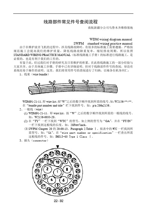
线路部件常见件号查阅流程南航新疆分公司乌鲁木齐维修基地WDM wiring diagram manualSWPM standard wiring practice manual 由于在维护波音飞机的过程中,涉及线路故障时,有很多的标准施工需要遵循。
严格按规范施工会提高我们的维护质量,降低线路故障重复率,缩短排故周期。
所以依照STANDARD WIRING PRACTICE MANUAL(标准线路施工手册)的标准进行线路施工,是必要的,也是有利于我们的工作的。
有鉴于此,经过我们对手册的研究及日常维护的积累,在此将线路施工的一部分经验与大家共享。
由于具体施工步骤,手册中已有详细说明,但对于线路部件件号的查阅,却没有系统而易于操作的说明。
这里,我们将常用件号的查阅进行了归纳,以飨各位机务同仁:1、线束(wire bundle)WDM91-21-11。
即wire list。
按“W”之后的数字顺序找到所需的线号。
如:W2156-**-**。
在“bundle part number and title”栏下找到件号。
如:p/n 286n2156。
2、一根线(wire)(1)WDM91-21-11。
即wire list,按“W”之后的数字顺序找到所需的一根线的线号。
如:W2156-0033-20。
(2)在“TY”一栏下找到“WTC”的型号,如上例的型号为“GA”。
并在“FT/IN”一栏下找到这根线的长度,如:28Feet7inch。
(3)SWPM Chapter 20的20-00-13,Paragraph 2.Table Ⅰ。
按表中的WTC一栏找到所需型号,如:“GA”。
在“wire part number or specification”一栏查出所需这根线的件号。
如:BMS13-60 Type 1 Class Ⅰ。
3WDM CHAPTER20,在“EQUIPMENT LIST”中,按字母顺序找到所需插头设备号。
如何查询波音常见电气元件信息

三,如何查询接线片件号
★接线片件号信息:321894, 322338 or 323750
三,如何查询接线片件号
★但经常会遇到不完整的件号,还需通过SWPM补充完成 例如:例如下图TT为LR,对应的主件号信息为: BACT12E(),接线端尺寸#10,线径为18号线
三,如何查询接线片件号
★通过SWPM前言的索引内容查询,需参考SWPM20-30-11
二,如何查询插头和销钉件号
5,参考SWPM20-61-11首页的DESCRIPTION中找到INSERT CONFIGURATIONS对应的PARAGRAPH 和PAGE:66
★ COUNT/SIZE为: 2 / 16
二,如何查询插头和销钉件号
6,参考SWPM20-61-11首页的DESCRIPTION中找到CONTACT PART NUMBERS AND DESCRIPTIONS 对应的PARAGRAPH 和 PAGE:51
★回到SWPM20-30-12,通过线径(18)换算出CAU为19
三,如何查询接线片件号
★依据SWPM20-30-11,查表得出接线片件号:
线径18 CAU 19 接线端尺寸#10 主件号信息为:BACT12E() 查表得出件号:BACT12E18
四,如何查询死接头件号
★查询737前缘过渡传感器的死接头件号(B-5116为例)
四,如何查询死接头件号
3,参考SWPM20-30-12,通过线径,找出其对应的CAU号 线径20,CAU12。
4,依据SWPM20-30-12,ASSEMBLY OF SPLICES 可见件号信息, 见第6页
四,如何查询死接头件号
5,见下图,依据“线径20,CAU12”信息。 参考WDM,此死接头连接2条导线。所以件 号为:D-436-37, (这里的件号指整个死 接头包括外面的塑料绝缘套)
IPC手册查询

练习
查找飞机号为B-5257的整流罩防冰活门的 相关信息。
练习
查找飞机号为B-5257的可伸缩着陆灯的相 关信息。
练习
查找飞机号为B-5257的DVD播放器的相关 信息。
一类是零件号知道,要确定零件的名称以 及其在飞机系统中的位置;
一类是只知道零件的名称或者零件在飞机 系统中的位置,要借助零件目录图手册 确定零件号
IPC 的查阅方法
当零件的件号已知时,我们可以查找数码 索引(Numerical Index)。
数码索引分为两部分: 字母数字索引(Alpha-Numerical Index
图形参考
Illustration reference 指与该零件功能相关 的图示,在所指示图中该零件由虚线划 出
附属零件
Attaching Parts 指组件安装时需要的螺钉 、螺母、垫片、卡子等,在内容中以 “Attaching Parts”开头由“ - * - ”结束 。
IPC 的查阅方法
IPC 的有效性问题
有效性代码: IPC 是提供各零、部件件号的文件,飞
机上所安装的每一个零件都有一个有效 性代码,同一架飞机上零、部件的有效 性代码相同。 有效性代码是由有效性起始码(三位数字 )和有效性终止码(三位数字)组成的 六位数字。
IPC 的有效性问题
每一架飞机都有自己的有效性代码,在使 用IPC 之前,要先明确你所要查找的零 件是哪一架飞机的,然后记下该飞机的 有效性代码,查找到件号后,要核对该 件号是否具有相同的有效性代码。
该信息由V 字母打头外加五位的数字或者 字母指代该供货商的地址、名称信息, 可在手册前言部分ication Number 指该组件遵循波音的 相关质量要求的编号,这种编号在没有 相应供货商取得相关资质时可以代替件 号(Part Number)使用也可以使用BAC 打头的波音标准件号,因此规范代码也 可以在件号索引中查到,而且后面还可 以跟随取得同样质量要求的可选件号。
波音手册概述

波音手册概述
目的:
本课件简单介绍维修工作中所常用的各类 波音手册及使用时的相互关系。
故障隔离手册(FIM)
故障隔离手册提供了故障隔离的程序以修复飞机上 的各类故障。
结构修理手册(SRM)
结构修理手册的内容是对飞机结构的损伤及对其进 行修理作出指导性的说明。
波音手册概述
维 修 文 件 与 维 修 工 作 的 关 系 如 右 图 所 示
维修计划文件给出各类计划维修检查的工作项 目。航空公司可根据MPD制定维修方案和计划维修 工卡。
放行偏离指南(DDG)
放行偏离指南提供波音建议的放行飞机所需的 最低设备要求和相应的程序。
波音手册概述
标准线路操作手册(SWPM)
标准线路操作手册提供了对所有波音飞机上导线和 各类电气元件维护和修理的标准操作程序。
波音手册概述
飞机维护手册(AMM)
飞机维护手册的主要内容是维护飞机的实际操 作与程序,包括有拆装,检查和测试等等。其内容 还包括对飞机各个系统工作原理的描述。
零部件图解目录(IPC)
零部件图解目录提供了部件更换的资料,主要 是部件的件号和图解及与部件相关的一些信息(例 如:供应商、互换性,规范号和改装等)
波音手册概述
波音的各类维修文件是在相应飞机上做维修工作 (计划的与非计划的)的依据。 常用的维修文件有:
◆ AMM 飞机维护手册 ◆ WDM 线路图手册 ◆ SSM 系统原理图手册 ◆ MPD 维修计划文件 ◆ SRM 结构修理手册 ◆ IPC 零部件图解目录 ◆ FIM 故障隔离手册 ◆ SWPM 标准线路操作手册 ◆ DDG 放行偏离指南
波音手册查询
波音手册查询第八章手册查询Manuals1、设备清单 Equipment List先通过 WDM中的线路图和 SSM,找到电子电气设备的设备号(空客飞机为功能号FIN)设备号用指定的字母数字来表示。
然后通过设备号在设备清单中可找到相应的电气设备的件号。
(1)REV:修改情况说明。
新增内容用“A”表示,修改内容用“R”表示。
(2)MOD:改装情况说明,暂空。
(3)EQUIP:设备号,以字母开头,有字母数字共同组成。
一般位数不足的,补零。
(一般D表示插头,C表示跳开关, E设备架, G表示发电机,N表示指示器, P表示面板, R表示继电器、变阻器、整流器等……)。
8-1 波音手册查询在波音飞机系列中,标准线路施工用到的手册查询主要有WDM(线路图手册)和 SWPM(标准线路施工手册),但有时还要借助于 IPC手册和 SSM(系统原理手册)。
一、WDM手册从该手册中我们可以得知各系统及部件的线路图,从线路图中,我们可以找到相应的电气号以及导线线号等信息。
此外 WDM中还有 WDM91章。
WDM91章分为图表和清单两大部分。
其中图表包括:飞机站位布局,线路区域,主线束走向,面板及设备架位置,跳开关面板图,脱开支架图和主线束信息等几个部分。
清单包括:设备清单,跳开关清单,脱开支架清单,导线清单,接地清单,导线连接管清单,接线片清单和连接清单等几个部分。
(4)OPT :选装说明。
“1”表示第一可选的。
(5)PART NUMBER:设备件号。
(6)PART DESCRIPTION:设备名称,描述。
(7)USED ON DWG:该部件所在图纸,图纸包含了该部件详细安装情况。
(8)CH 20 REF:仅适用于插头,指明该插头在标准线路施工手册 SWPM中的章节号,可直接进入标准线路施工手册中的子章节。
(9)VENDOR:供应商代码。
(10)QTY:部件个数。
(11)DIAGRAM:该部件所在线路图章节号。
(12)STATION-WL-BL:部件定位信息,站位 -水线-纵剖线。
波音技术手册学习资料

编写:杨健
目录
➢ 波音手册概述 ➢ 飞机维护手册介绍 ➢ 故障隔离手册介绍 ➢ 线路图手册介绍 ➢ 零部件图解目录介绍 ➢ 使用实例
1
波音手册概述
目的:
本教材通过对波音737NG常用的几本手册的介绍,熟 悉并掌握手册查询和使用的方法。
组成:
本课件由以下六个部分组成
概述 飞机维护手册(AMM) 零部件图解目录(IPC) 故障隔离手册(FIM) 线路图手册(WDM) 系统图手册(SSM)
页块:
页块用来划分同一个章节号内不同类型的内容,各页 块的定义如下:
飞机维护手册(AMM)—使用查询
页块:
页块的编号显示在每页的右下角
根据所需的工作找到适用的工卡
工卡号
飞机维护手册(AMM)—使用查询
页块:
1-99 描述/功能 101-199 部件位置 201-299 维护操作 301-399 勤务 401-499 拆卸/安装 501-599 调整/测试 601-699 校验/检查 701-799 清洁/喷漆 801-899 修理
737-NG型飞机的AMM,每个系统,子系统 的第一项内容是对该系统的介绍和功能描 述。
对整个电 源系统的 综述
对发电机驱动系统的介绍,主要包括: 概述、部件的详细介绍,系统的功能描 述(工作原理)。
飞机维护手册(AMM)—使用查询
页块:
1-99 描述/功能 101-199 部件位置 201-299 维护操作 301-399 勤务 401-499 拆卸/安装 501-599 调整/测试 601-699 校验/检查 701-799 清洁/喷漆 801-899 修理 901-999 DDG维护程序
系统原理图手册以图纸的形式描述飞机各个 系统的工作原理。图纸只画出各系统或子系统 的LRU之间的连接。
波音手册查询(高级)
故障隔离手册(FIM)—故障类型
此页块包含了系统和设备的各类测试以及对 某些部件的调整的要求。 测试一般分为三个等级: 操作测试( Operational Test):仅为 了证实系统或组件可正常工作
功能测试( Functional Test):需判 定系统或组件所有功能正常并符合系统或 组件的最小容许要求和设计规范 系统测试( System Test):包含所有的 调节规定和容限,以使系统和组件的特性 保持在最大效能和设计规范。
飞机维护手册(AMM)—使用查询
页块:
1-99 描述/功能 101-199 部件位置 201-299 维护操作 301-399 勤务 401-499 拆卸/安装 501-599 调整/测试 601-699 校验/检查 701-799 清洁/喷漆 801-899 修理 901-999 DDG维护程序
20章内容介绍:
接地:
机身接地的标准程序 和对于静电敏感装置的标 准操作程序。
飞机维护手册(AMM)—特殊章节
20章内容介绍:
扭矩值: 给出各类标准件(螺栓、 螺帽、夹子,卡箍,管路接 头)的标准扭矩值。
飞机维护手册(AMM)—特殊章节
20章内容介绍:
杂项:
主要内容包括:跳 开关的复位操作程序, 导线和导线束的检查、 清洁,保护程序以及电 子设备组件的清洁程序。
20章内容介绍:
修理与更换: 航空器上所安装的 各类机械元件(如:钢 索、钢索滑轮、液压软 管,0型封圈)和电气元 件(如:设备组件、电 路卡,爆炸帽)的标准 维护程序。
波音737-800_NP20操作手册

正常程序NP章详细程序第20节外部安全检查—机长或副驾驶操纵面和轮挡・・・・・・・・・・・・・・・・・・・・・检查目视检查所有活动的操纵面无障碍以及轮挡挡好。
维护状态・・・・・・・・・・・・・・・・・・・・・・・检查证实维护状态适航。
如需要,应确定飞机符合放行标准。
驾驶舱安全检查—机长或副驾驶下列检查在假设飞行组进入正常位置之前实施。
电瓶电门・・・・・・・・・・・・・・・・・・・・・・・接通护盖—保险液压电动泵电门・・・・・・・・・・・・・・・・・・・・・关起落架手柄・・・・・・・・・・・・・・・・・・・・・・放下所有起落架绿色指示灯—亮驾驶舱预先准备—机长或副驾驶地面电源电门(如地面电源可用)・・・・・・・・・・・・接通电源断开指示灯—灭故障/不工作探测・・・・・・・・・・・・・・・・・・・・检查过热探测电门—正常测试电门—保持在“故障/不工作”位证实主警告、过热/探测信号牌、故障指示灯和APU火警探测器不工作指示灯亮。
如故障指示灯不亮,故障探测系统不工作。
如APU火警探测器不工作指示灯不亮,不得使用APU。
火警/过热警告・・・・・・・・・・・・・・・・・・・・・检查注:当APU工作时,进行这项测试前要提醒地面人员。
APU地面控制面板上的火警指示灯会亮且喇叭会响。
测试电门—保持在过热/火警位证实火警铃响,主火警指示灯、主注意指示灯和过热/探测信号牌亮。
主火警指示灯—按压证实主火警指示灯灭和警铃声响停止。
证实1号发动机、APU、2号发动机火警电门及1号与2号发动机的过热指示灯亮、如交流汇流条有电,证实轮舱火警指示灯亮。
如一个发动机火警电门和一个发动机过热指示灯不亮,表明一个火警探测环路不工作。
灭火瓶测试电门・・・・・・・・・・・・・・・・・・・・检查将测试电门放在1位,证实绿色灭火瓶测试指示灯亮。
松开电门,证实所有指示灯灭。
2位的测试方法一样。
APU・・・・・・・・・・・・・・・・・・・・起动/连接汇流条APU发电机断开汇流条指示灯亮时:APU发电机汇流条电门—接通电源断开指示灯—灭注:APU作为引气源之前,建议让APU先工作一分钟。
波音747中文操作手册
波音747-400 操作手册目 录主飞行显示(Primary Flight Display) (4)导航显示(Navigation Display) (7)自动飞行(Automatic Flight ) (9)发动机指示及机组警告系统显示(Engine Indication and Crew Alerting System (EICAS) display) (12)电气系统(Electrical System) (14)液压系统(Hydraulics system) (16)发动机(Engines ) (17)燃油系统(Fuel System ) (18)气源系统(Pneumatics ) (20)其它多功能显示页(Other MFD pages) (22)飞行管理计算机(Flight Management Computer) (24)FMC控制显示组件(FMC Control Display Unit (CDU) ) (25)CDU页(CDU pages ) (26)CDU飞行前程序(CDU Preflight Procedure) (26)IDENT页(IDENT page ) (27)位置初始页(POS INIT page) (27)航路页(ROUTE page ) (27)性能初始页(PERF INIT page ) (28)推力限制页(THRUST LIM page) (29)起飞参考页(TAKEOFF REF page) (30)进近参考页(APPROACH REF page ) (31)航段页(LEGS page )................................................................................... . (32)飞行进程页(PROGRESS page) (34)起飞、降落页(DEPARTURES and ARRIVALS pages ) (35)VNAV爬升页(VNAV CLB page) (36)VNAV巡航页(VNAV CRZ page) (37)VNAV下降页(VNAV DES page) (38)等待页(HOLD page) (39)导航无线电页(NAV RADIO page) (41)近地警告系统(Ground Proximity Warning System (GPWS)) (42)无线电面板(Radio panel ) (43)自动刹车(Autobrakes) (44)乘客信息(Passenger Signs ) (44)时钟(Clock ) (44)主飞行显示(PDF)PFD布局空速指示器指令速度显示方式控制面板(MCP)中选择的速度,或当MCP速度窗空白时显示FMC的指令速度收襟翼速度指示当前(10度襟翼)或下一个(5度襟翼)襟翼位置的收襟翼速度。
波音737飞行机手册说明书

CHAPTER15---ICE AND RAIN PROTECTION SYSTEMPage TABLE OF CONTENTS15--00 Table of Contents15--00--1INTRODUCTION15--10 Introduction15--10--1ICE DETECTION SYSTEM15--20 Ice Detection System15--20--1 System Circuit Breakers15--20--5WING ANTI-ICE SYSTEM15--30 Wing Anti--Ice System15--30--1 System Circuit Breakers15--30--6ENGINE COWL ANTI-ICE SYSTEM15--40 Engine Cowl Anti--Ice System15--40--1 System Circuit Breakers15--40--5 AIR DATA ANTI-ICE SYSTEM15--50 Air Data Anti--Ice System15--50--1 System Circuit Breakers15--50--4 WINDSHIELD AND SIDE WINDOW ANTI-ICE SYSTEM15--60 Windshield and Side Window Anti--Ice System15--60--1 System Circuit Breakers15--60--5WINDSHIELD WIPER SYSTEM15--70 Windshield Wiper System15--70--1 System Circuit Breakers15--70--2LIST OF ILLUSTRATIONSINTRODUCTIONFigure15--10--1Anti--Iced Areas15--10--2ICE DETECTION SYSTEMFigure15--20--1Ice Detection System--Schematic15--20--2 Figure15--20--2Ice Detection System15--20--3 Figure15--20--3Anti--Ice System EICAS Indications15--20--4WING ANTI-ICE SYSTEMFigure15--30--1Wing Anti--Ice System Schematic15--30--2 Figure15--30--2Wing Anti--Ice Controls15--30--3 Figure15--30--3Anti--Ice Synoptic Page15--30--4 Figure15--30--4Wing Anti--Ice System EICAS Indications15--30--5ENGINE COWL ANTI-ICE SYSTEMFigure15--40--1Engine Cowl Anti--Ice System--General15--40--2 Figure15--40--2Anti--Ice Synoptic Page15--40--3 Figure15--40--3Engine Cowl--Anti--Ice EICAS Indications15--40--4 AIR DATA ANTI-ICE SYSTEMFigure15--50--1Air Data Sensor Anti--Ice System15--50--2 Figure15--50--2Air Data Sensor Anti--Ice EICAS Indications15--50--3WINDSHIELD AND SIDE WINDOW ANTI-ICE SYSTEMFigure15--60--1Windshield Temperature Control15--60--2 Figure15--60--2Windshield and Side Window Anti--Ice Controls15--60--3 Figure15--60--3Windshield and Side Window Anti--Ice EICAS Indications15--60--4 WINDSHIELD WIPER SYSTEMFigure15--70--1Windshield Wiper Control Panel15--70--11.INTRODUCTIONIce and rain protection is provided for the wing leading edges,engine intake cowl,windshields,side windows and the air data probes and sensors.An ice detection system alerts the flight crew of impending icing conditions.Hot bleed air from the engine compressors is used to anti-ice the wing leading edges and engine intake cowl.Electrical power is used to anti-ice the windshields,side windows,air data probes and sensors.Electrical windshield wipers provide rain removal for the pilot and copilot’s windshields.A bleed air leak detection system monitors the bleed air ducting for leaks andovertemperature(refer to Chapter19).Ice and rain protection system warnings and cautions are displayed on the EICAS primary page.Status and advisory messages are displayed on the EICAS status page.A general view of the pneumatic anti-icing system is presented as a diagram on the EICAS A--ICE synoptic page.Anti---iced AreasFigure15---10---11.ICE DETECTION SYSTEMThe aircraft is equipped with an ice detection system that alerts the flight crew of impending icing condition.The ice detection system consists of two independent ice detectorassemblies located on each side of the forward fuselage.Each detector assembly includesa detector unit and a probe that extends into the airstream.The ice detection system isoperational whenever AC power is available on the aircraft.The ice detectors interface with the data concentrator units(DCU)to provide visualindications of icing conditions.When the probes detect an ice build up,a signal is sent by the unit to the EICAS and at the same time electrical power is used to de--ice the probe.When the probe is de--iced,it is then ready to detect ice formation again.Ice Detection System---SchematicFigure15---20---1Figure15---20---2<1001> Figure15---20---3A.System Circuit BreakersSYSTEM SUB--SYSTEM CB NAME BUS BAR CBPANELCBLOCATIONNOTESIce Detection ICE DET1ACESSENTIAL1T11System Ice DetectorsICE DET2AC BUS22A14THIS PAGE INTENTIONALLY LEFT BLANK1.WING ANTI--ICE SYSTEMThe wing anti-ice system prevents ice formation on the wing leading edge by heating the surface using hot engine bleed air.The hot bleed air is supplied through insulated ducting and released through piccolo tubes to the inner surface of the wing and slat leading edges.The wing anti-ice system is divided into identical left and right systems.In normal operation, each engine supplies bleed air to its respective wing anti-ice system.The systems areconnected by a,normally closed,wing anti--ice cross bleed valve.In the event one system fails,the cross bleed valve is opened to permits cross bleed between systems.This ensures that wing anti--icing is maintained to both systems.The system is manually activated and is automatically controlled by a dual channel digital anti-ice and leak detection controller(AILC).The AILC controls the wing anti-ice system using electrical inputs received from skin temperature sensors located at each wing leading edge.The AILC modulates the respective wing anti-ice valve open or closed as necessary to prevent ice formation.Each of the two channels of the AILC has the capability to control both left and right anti-ice valves.Figure15---30---1Wing Anti---Ice ControlsFigure15---30---2Figure15---30---3<1001> Figure15---30---4A.System Circuit BreakersSYSTEM SUB--SYSTEM CB NAME BUS BAR CBPANELCBLOCATIONNOTESIsolation Valve WING A/ICEISOL BATTERYBUS2N5Wing Anti-IceA/ICE CONTCH A DC BUS11D7 ControllerA/ICE CONTCH BDCESSENTIAL2T11.ENGINE COWL ANTI--ICE SYSTEMThe engine cowl anti-ice system is used to prevent ice formation on the engine intakeleading edges.This is done by using hot engine bleed air to heat the leading edge surface.The hot bleed air is supplied to the intake leading edges through respective L/R cowlanti--ice shutoff valves.Bleed air is distributed through insulated ducting and an air mixing tube before entering a double walled duct in the engine cowl leading edge.The innerportion of the duct carries the bleed air.In the event of a rupture of the inner wall,a bleed leak detector transducer mounted in the outer wall supplies a bleed leak signal to the EICAS to illuminate the L/R COWL A/I DUCT warning message.The left and right cowl anti-ice shutoff valves are manually controlled by respective LH and RH COWL switches on the ANTI--ICE control panel.Crew activation of each system,opens the respective engine cowl anti-ice shutoff valve.The shutoff valves are electricallycontrolled and pneumatically operated.Valve status is displayed on the EICAS,ANTI--ICE synoptic page.2.T2SENSOR PROBE ANTI--ICINGA fan inlet temperature sensing probe(T2),mounted on the engine cowling,is used toprovide temperature data to the FADEC.The FADEC uses the information as one of the sensing parameters to set engine power and to control the compressor variable geometry stator vanes.The probe also contains a built--in heating element that is used to anti--ice the probe.Electrical heating power to the probe heating element is controlled by the FADEC.Testing of the T2heater function is done automatically by the FADEC,which initiates asystem check after engine shutdown on the ground.Following right engine shutdown,electrical power must be maintained on the aircraft for at least one minute to make sure that the FADEC has sufficient time to successfully complete the test.The FADEC verifies T2heater function by energizing the heater and looking for an appropriate temperature rise during a30second period.Following a successful test,the next test will be initiated after the next ground engineshutdown.If the FADEC(through channel A)cannot energize the T2heater,the FADEC will automatically switch to channel B to conduct the test(after a30second time delay).If the T2heater test fails on both channels,the respective L/R ENG TAT HEAT caution message will be displayed on the EICAS primary page and the FADEC will not attempt to energize the T2heater.Engine Cowl Anti---Ice System---GeneralFigure15---40---1Anti---Ice Synoptic PageFigure15---40---2<1001> Figure15---40---3A.System Circuit BreakersSYSTEM SUB--SYSTEM CB NAME BUS BAR CBPANELCBLOCATIONNOTESAnti-Ice A/ICE VALVEL ENG BATTERY N3Engine Cowl Anti-Ice Anti IceValves A/ICE VALVER ENGBUS2N4Anti IceT2HEATER L DC BUS11F4 T2HeatersT2HEATER R DC BUS22F4THIS PAGE INTENTIONALLY LEFT BLANK1.AIR DATA ANTI--ICE SYSTEMAir data probes and sensors are located on the left and right sides of the forward fuselage and extend into the airstream.The air data sensor(ADS)anti-ice system consists ofintegral,self regulating,heating elements for the air data sensors and probes.The ADS heaters prevent ice formation that may cause erroneous air data information.ADS anti-icing is achieved by electronically controlling the heating elements.The air data sensor heating system is activated automatically on the ground and in flight.The ground mode has two operational heating modes,automatic and manual.In automatic mode,when either engine generator is on and the LH and RH PROBES switches,(on the ANTI--ICE control panel)are OFF,the LH and RH pitot probes and the standby pitot probe are heated at half power(automatic mode is not functional when the aircraft is beingpowered by the APU generator or external power).The static ports and the AOA vanes are not powered automatically in the ground mode.For manual mode,the static ports and the AOA vanes can be heated by selecting the LH and RH PROBES switches to ON.In the flight mode,the automatic control function is completely independent of the control switches.The controllers automatically supply full power to all the air data probes andsensors.The LH and RH PROBES switches have no effect on the function of thecontrollers.The air data probes and sensors are monitored and controlled by three independent and identical controllers.Controller1monitors the heater elements for the left pitot,left angle of attack(AOA)vane and left static port.Controller2monitors the right pitot,right AOA vane and right static port.Controller3monitors the standby pitot and total air temperature(TAT) probe.Air Data Sensor Anti---Ice SystemFigure15---50---1Air Data Sensor Anti---Ice EICAS Indications <1001>Figure 15---50---2Status PageA.System Circuit BreakersSYSTEMSUB--SYSTEMCB NAMEBUS BARCB PANEL CB LOCATIONNOTESTAT HeaterHEATERS TATA12HEATERS PITOT R AC BUS 1A14Pitot HeatersHEATERSPITOT L T7HEATERS PITOT STBY ACESSENTIAL1T9HEATERS AOA LT8Air Data Sensor AOA HeatersHEATERS AOA R AC BUS 1A13Anti-IceHeatersHEATERS STATIC RDC BUS 1G14Static HEATERS STATIC L S1HEATERS ADS CONT 1DC2S2ControllersHEATERS ADS CONT STBY ESSENTIALS3HEATERS ADS CONT 2DC BUS 11G131.WINDSHIELD AND SIDE WINDOW ANTI--ICE SYSTEMWindshield and side window anti-icing is achieved by electrically heating the windshield and side windows.Each windshield and side window incorporates an electrical heating element and three temperature sensors.One sensor is used for normal temperature control and another is used for overheat detection.The third sensor is a spare,and is used should one of the other sensors fail.The amount of heat supplied to the windshields and side windows is controlled by fouridentical temperature controllers,one for each window.The controllers automaticallyregulate power to the heating elements as selected by the LOW/HI WSHLD switches on the ANTI--ICE control panel.When an overheat condition is detected,the associated controller removes the power to the heater element and posts a caution message on the EICASprimary page.Windshield Temperature ControlFigure15---60---2<1001> Figure15---60---3A.System Circuit BreakersSYSTEMSUB--SYSTEMCB NAMEBUS BARCB PANEL CB LOCATIONNOTESHEATERSL WSHLD AC BUS 1A10--A11HEATER L WIND ACESSENTIAL 1U10HeatersHEATERS R WSHLD A10--A11Windshield HEATER R WIND AC BUS 22C7and Side Window Anti-Ice HEATERS CONT L WSHLDDC BUS 11G12Anti IceHEATERS CONT L WIND DCESSENTIAL S4ControllersHEATERS CONT R WSHLD2G13HEATERS CONT R WINDDC BUS 2G14Flight Crew Operating Manual CSP C--013--0671.WINDSHIELD WIPER SYSTEM The windshield wiper system is designed to remove rain and/or snow from the pilot and co-pilot’s windshields at speeds up to 250knots.The windshield wiper system consists of independent pilot and copilot systems.Each system consists of a windshield wiper and motor with both systems being controlled by an electronic control unit.Each pilot has a selector,located on the WIPER control panel that actuates both wipers.Under normal operations,both wipers will operate in the same mode when selected from either panel.If each selector is set to a different mode,the last selection made overrides the previous selection.If one wiper system fails,the remaining system will still be functional.Flight Crew Operating Manual CSP C--013--067A.System Circuit Breakers SYSTEM SUB--SYSTEM CB NAME BUS BAR CB PANEL CB LOCATION NOTESWindshield WIPER PILOT DC BUS 11G5Wiper System Wipers WIPER C/PLT DC BUS 22G5。
波音747中文操作手册

波音747-400 操作手册目 录主飞行显示(Primary Flight Display) (4)导航显示(Navigation Display) (7)自动飞行(Automatic Flight ) (9)发动机指示及机组警告系统显示(Engine Indication and Crew Alerting System (EICAS) display) (12)电气系统(Electrical System) (14)液压系统(Hydraulics system) (16)发动机(Engines ) (17)燃油系统(Fuel System ) (18)气源系统(Pneumatics ) (20)其它多功能显示页(Other MFD pages) (22)飞行管理计算机(Flight Management Computer) (24)FMC控制显示组件(FMC Control Display Unit (CDU) ) (25)CDU页(CDU pages ) (26)CDU飞行前程序(CDU Preflight Procedure) (26)IDENT页(IDENT page ) (27)位置初始页(POS INIT page) (27)航路页(ROUTE page ) (27)性能初始页(PERF INIT page ) (28)推力限制页(THRUST LIM page) (29)起飞参考页(TAKEOFF REF page) (30)进近参考页(APPROACH REF page ) (31)航段页(LEGS page )................................................................................... . (32)飞行进程页(PROGRESS page) (34)起飞、降落页(DEPARTURES and ARRIVALS pages ) (35)VNAV爬升页(VNAV CLB page) (36)VNAV巡航页(VNAV CRZ page) (37)VNAV下降页(VNAV DES page) (38)等待页(HOLD page) (39)导航无线电页(NAV RADIO page) (41)近地警告系统(Ground Proximity Warning System (GPWS)) (42)无线电面板(Radio panel ) (43)自动刹车(Autobrakes) (44)乘客信息(Passenger Signs ) (44)时钟(Clock ) (44)主飞行显示(PDF)PFD布局空速指示器指令速度显示方式控制面板(MCP)中选择的速度,或当MCP速度窗空白时显示FMC的指令速度收襟翼速度指示当前(10度襟翼)或下一个(5度襟翼)襟翼位置的收襟翼速度。
波音737飞行操作手册

波音737飞行操作手册【波音737飞行操作手册】看看飞行员都做什么?里面包含了机组的飞行前各项准备工作和检查单口令。
一.驾驶舱初步准备驾驶舱安全检查电瓶电门---接通直流电流表--电瓶位,检查电压26±4伏,电流表指零电动液压泵电门---关闭起落架手柄---放下,三个绿灯检查地面电源电门--打开APU--起动起动:APU起动电门---起动位松开至"ON"位,当APU发电机关断汇流条灯亮(蓝色),APU起动完毕。
APU电源---接通油泵电门---ON位襟翼手柄位置与襟翼位置指示器一致。
惯导基准系统(IRS)方式选择钮扳至导航位(NAV)。
核实两个直流接通灯(ONDC)亮,校准灯(ALIGN)亮。
显示选择钮放在航向/状态位(HDG/STS)。
二.驾驶舱预先准备FMC/CDU…输入现在飞机实际位置(PPOS)位置起始页…选择使用可用的最精确的信息,在调定IRS位置线上输入现在位置。
音频选择板-一调定。
飞行操纵面板…检查所有5个电门护盖--盖好。
备用襟翼主电门-OFF。
偏航阻尼器电门…OFF仪表和导航转换电门…正常位导航转换和显示电门…自动和正常燃油系统…检查翼梁活门关闭灯暗亮。
核实过滤旁通灯灭。
交输选择器一关。
核实"活门开"灯灭。
燃油量--检查。
燃油泵电门--OFF。
厨房电源电门--ON电气系统---调定AC表选择电门---APUGEN备用电源电门-AUTO汇流条转换电门-AUTO设备冷却电门--正常位紧急出口灯电门---预位禁止吸烟电门-ON系好安全带电门-OFF 风挡刷选择器--OFF风挡加温电门--OFF空速管加温电门--OFF大翼防冰和发动机防冰电门---OFF液压---正常电动液压泵开,发动机液压泵开。
油量表-高于RF位。
电动液压泵---关闭。
增压指示器--检查座舱压差-零座舱高度-机场标高座舱升降率-零外部灯光电门---按需点火选择电门发动机起动电门--OFFEFIS控制面板---调定最低高度(MINIMUMS)--基准选择器选择无线电(RADIO)或气压(BAROMETRIC)位气压基准选择器--调定VOR/ADF电门--按需中央电门CENTRE--按需距离范围选择器--按需活动TRAFFIC电门--按需地图电门---按需导航电门---按需选择PMC、ANS-左或ANS-右位置MCP板调定飞行指引仪电门-OFF自动油门电门-OFF航向窗-起飞跑道航向转弯坡度角限制-按需高度-起飞的起始高度或ATC的指定高度自动驾驶-脱开时钟--调定飞行仪表--调定飞行方式信号牌--空白高度表---调定高度表上的橘色游标调机场标高加1000英尺修正海压地图导航显示---正确航路--显示正确备用仪表--调定备用地平仪--调定调定地平线指示--核实姿态正确。
飞机维护手册AMM查询教程文件
飞机维护手册A M M查询飞机维护手册第一节维护手册的概述和结构3.1.1维护手册的概述飞机维护手册是外场维护中使用最频繁的一本手册,是飞机工作人员的工作指南,这本手册的内容丰富、充实、多样。
而且,在维修文件历史的传承中,出现了很多维护手册内容的分支,在不同时代出现了不同内容的维护手册,新旧不同版本的维护手册的内容也不尽相同。
最新版本(波音737-600/700/800/900飞机)的维护手册在工作的分类上,将通用性、原理性的信息另成一册称为系统描述部分(Systems Description Section, SDS),继承了原来(波音737-300/400/500飞机)在01-99页部分的概述内容,由于这部分内容不涉及工作内容,波音公司可以免责其中的错误。
而原有的第五章定时性检修的数据,都写在维修计划数据MPD中,这部分不再写在AMM中,现在第五章的内容只包含非定时性的维修检查。
而原来停场封存数据专门成册的出版物,现在写在AMM手册11章中。
本书的第二章第一节简要介绍了AMM手册,AMM手册实际上是工作程序的集合,针对航线可更换件LRU进行的维护步骤和程序的集合。
它是由飞机制造厂商发布的,依据各种组件、系统、APU、发动机的供货商提供的数据和制造厂商的技术数据综合编写而成,手册基本上都是严格按照ATAl00格式进行编排的,所以,掌握ATA100内容对手册的查阅是非常重要的。
下面以波音737-300飞机为例介绍AMM手册。
学会查阅AMM的工作步骤,是机务维护人员的必修课程,是以维护手册为标准进行施工的必要前提。
3.1.2维护手册AMM的结构维护手册的结构图已经出现在第二章第三节的内容中,维修手册依据ATAl00的章节形式“**--**--**”进行划分。
除此之外维护手册根据自身的性质,按照工作的不同内容,将页码分成不同的区段。
从表3-1中不难看出,页码的第一位是功能位,代表该页码段的工作内容和性质。
波音手册查询(高级)

手册的内容
操作步骤
针对每个维护和操作任务,手册 都提供了详细的步骤说明,包括 工具使用、安全注意事项等。
故障排除
对于常见的故障和问题,手册提 供了故障排除流程和方法,指导 维修人员快速定位和解决问题。
性能参数与规格
手册包含了飞机的性能参数、系 统规格和技术规格,为维护人员 提供参考依据。
手册的版本与更新
详细描述
在波音手册数据库中,用户可以通过输入关键词(如飞机型号、系统、部件等) 来查找相关信息。系统会根据关键词自动匹配相关内容,并提供给用户查询结 果。
分类查询
总结词
按照手册的分类结构,逐级查找所需 信息。
详细描述
波音手册通常按照飞机结构、系统、 部件等进行分类编排。用户可以根据 手册的分类结构,逐级展开目录,找 到所需信息的具体位置。
更换磨损部件、修复液 压系统或调整控制电路 ,确保起落架正常工作 。
案例二:某型飞机发动机维护与保养
保养措施
维护计划
定期检查发动机的工作状态,包 括气缸、燃油系统和进排气系统 等关键部件。
清洁发动机内部、更换磨损部件、 调整燃油混合比和更换机油等。
预防性维护
根据飞行小时数或周期性检查计 划,对发动机进行预防性维护, 以降低故障风险。
详细描述
系统提供筛选和排序功能,用户可以根据需要选择特定的筛 选条件(如飞机型号、系统类型等)对查询结果进行筛选, 同时还可以根据关键字、日期等对结果进行排序,方便用户 快速找到关键信息。
04
波音手册查询的应用与实践
手册查询在飞机维护中的应用
飞机维护手册
提供飞机维护和检查的程序、标 准和技术要求,确保飞机安全运
波音手册是一个系统化的资料体系, 了解其组织结构和编排方式有助于更 快地找到所需信息。
波音航空字典整理版本

波音航空字典整理版本31.Outer Compass Locator(LOM)32.Middle Compass Locator(LMM)3abeam (ABM)2absolute altitude2absolute pressure2ACARS2acceleration2accessory gearbox2accumulator3ACMS1actuator1ADC2ADF2ADI3aeronautical radio incorporated3agility tuning1aileron2aileron force limiter1air cleaner1air cycle machine1air data computer2air route traffic control center (ARTCC)1air traffic control1air traffic control (ATC)1air way1air/ground sensor2airborne vibration monitor2aircraft (or ARINC) communications addressing andreporting system 2aircraft condition monitoring system 1airfoil1airplane flight manual (AFM)2airport analysis3airport elevation/field elevation1airspeed (IDS,TDS)2airspeed bugs2airspeed index1airworthiness3algorithm1alloy2alpha speed2alpha vane1alternate3alternate3alternate aerodrome2altimeter setting2altitude acquire2altitude alert2altitude capability2altitude hold (ALT HOLD)2altitude intervention1ambient1ambient pressure1ambient temperature1ampere3amplitude1analog1analog-to-digital2and gate2aneroid2angle gearbox2angle of attack2angle of incidence1annunciations1annunciator2anode3anomaly1antenna1anti-icing1anti-skid2apex pin3appendix2approach mode1APU2arc3area navigation/rnav1ARINC1arm3artificial feel3aspirated tat probe1assembly3assumed temperature reduced thrust 1ATC 2ATE2atmospheric pressure1attitude2audio controuselector panel1autoland2automatic direction finder2automatic flight control system2automatic test equipment1autopilot2autopilot flight director system 2autothrottle 1auxiliary power unit2avionics1AVM2axial flow compressor1axis3backcourse approach2background data2baffle1balance tab3balanced field length2ball nut2ballast2bar out of view2barometric pressure2base metal1battery1battery bus1battery charger1bay1BCD2beacon1bearing2bellcrank,3bellows3bezel2bias3bilge1binary coded decimal1binary number system1bit1BITE1black box1blank display1bleed air1bleed valve2blocker door2blower2blowout panel2body gear2bonding jumper3boolean algebra1boost pump2borescope3bourdon tube1bracket3brake energy limit weight 2breather3buffet3buffet margin2bug speed1built-in test equipment 2bulkhead3bungee1bus2bus drum2bus protection panel2butterfly valve2buttock line1bypass valve1byte1cabin altitude2calibrate2calibrated airspeed (CAS) 2cam2cam-out2CAP2capacitance2capacitor1capture2card file3cascade3cascade vane1case drain2cathode2cathode ray tube1ceiling2celsius1center of gravity2centering cam1central processing unit2centrifugal flow compressor 3certified configuration 1CG2changeover2charging valve1check valve3checksum1chip detector2chord1circuit1circuit breaker2clearway 12clearway 21climb2climb limit weight2clock signal3coalescer3coaxial cable3coaxial shaft1combustion chamber2command bar3company route3compass locator2compensation2compensator2composite materials1compressor2compressor stall2compressor surge1computer2condenser2cone bolt1configuration1configuration deviation list(CDL) 1constant speed drive 2control area1control axes1control column1control surface1control tab2control zone2controlled airspace2conversion3coordinates1corrosion1cowl2CPU(central processing unit)3cross track3cross-channel1crossfeed1crossfeed valve2CRT(cathode ray tube)1cruise1cruise altitude1CSD(constant speed drive)3cure1cycle2damper3dashpot1data1data base1data bus2deceleration3decibel(db)3decision altitude/height(DA/H) 3decision height(DH)1 3decision height(DH)22decompression2de-energize1defuel1defueling valve1de-icing1delete3delta2demodulation2demodulator3departure control2depressurization valve1descent2detailed flight planning1detector3detent solenoid2deviation2diaphragm3dielectric1differential pressure2diffuser1digital1digital-to-analog3dihedral3diluter demand regulator1dim1diode2dipstick2dipstick1direct2direct memory addressing1disarm2disk valve(obsolete term-butterfly valve) 3dispatch deviation3dispatch deviations procedures guide 3displace threshold2distance measuring equipment(DME)2diversion2DMA(direct memory addressing)2DME fix2dock2dome light3domestic reserves3dorsal fin2down track fix(DNTKFX)1download1downlock1drag2drag brace2drag strut1drain valve1drawing3drift angle3driftdown2dutch roll2dynamic data3dynamometer3DZUS fastener2EADI(electronic attitude director indicator)3econ speed1EFIS(electronic flight instrument system)1EGT(exhaust gas temperature)2EHSI(electronic horizontal situation indicator)1EICAS(engine indicating and crew alerting system)2ejector2electrical fuse2electronic attitude director indicator(ADIorEADI)1electronic flight instrument system(EFIS)2electronic horizontal situation indicator(EHSIorHSI)1electrostatic discharge sensitive devices1elevator2empennage1energize1engine bleed air1engine indicating and crew alerting system(EICAS)2engine pressure ratio(EPR)3enroute fuel planning2EPR(engine pressure ratio)2equalization2equipment center1ESDS(electrostatic discharge sensitive devices) 2estimated time of arrive3eutectic solder3evaporation2exceedance2excitation1exhaust gas temperature3extrusion3eye reference position(ERP)2fahrenheit2fail operational3fail passive1fairing1fan air1fan cowl1fan cowl1fan(NO.1)1fan(NO.2)1fastener2fatigue or fatigue failure1fault isolation manual(FIM)1fault reporting manual(FRM)2faying surface1feedback3feeder fix2feel computer3ferry flight2fiberglass3field length limit weight3filiform corrosion1FIM(fault isolation manual)1fin2final approach2final approach course2final approach fix1fire wall1fix3fixed base simulation(FBS)1flag(NO.1)1flag(NO.2)2flame arrestor2flange2flap load limiter2flap retraction altitude2flap setting3flap speed schedule 1flap(leading edge) 1flap(trailing edge)1flight controls2flight deck effects1flight director3flight director pop-up (FDS)3flight information region (FIR,UIR)2flight level (FL)1flight management computer (FMC)2flight mode annunciator1flight plan3flight profile1flight spoiler3flight training device2float switch2float valve2flowmeter3fluorescent light1FMC, see - flight management computer 1FOD, see - foreign object damage3force balance valve1foreign1foreign object damage1FRM, see - fault reporting manual2fuel conservation2fuel control unit (FCU)1fuel flow1fuel heater3fuel jettison system3full flight simulation (FFS)3full-wave rectifier1gage pressure3galvanic corrosion1gasket3gasper air1gate (NO. 1)1gate (NO. 2)2gate valve2gateway1gear doors1generator2generator breaker(s) (GB)2gimbal assembly3girt bar2glide slope (GS)3glide slope/glide path intercept altitude2global navigation satellite systems (GNSS) 1global positioning system (GPS) (No. 2)1global positioning system (GPS) (No1)2go-around (GA)2go-around thrust3gradient3graphite2great circle route2gross performance2gross weight (GW)1ground1ground fault ( NO. 2)1ground fault (NO. 1)1ground speed (GS)1ground spoiler2ground support equipment (GSE)2grounding point (terminal)1GS, see - ground speed2GSE, see - ground support equipment 2guarded switch2GW, see - gross weight3hairline crack3hard-over2HDG HOLD, see - heading hold2HDG SEL, see - heading select1head end1heading2heading hold (HDG HOLD)2heading select (HDG SEL)1headwind1heat exchanger3height above airport (HAA)3height above touchdown((HAT)1hertz (Hz)3hexadecimal numbering system1high frequency (HF)2high speed taxiway/exit/turnoff (HST) 2hoist2hold/holding procedure1holding2holding fix2holding pattern2honey comb1horizontal stabilizer1hot battery bus1hub cap1hydraulic fuse2IAS, see - indicated airspeed1igniter (igniter plug)1ignition exciter1ignition system1illuminate1ILS, see - instrument landing system2improved climb performance1indicated airspeed (IAS)1indicator2inertial reference system2inflight performance3initial approach fix (IAF)2inlet guide vanes2inner loop control2inner marker1INOP, see – inoperative1inoperative2instrument flight rules (IFR)1instrument landing system3instrument meteorological conditions(IMC) 2instrument runway1integral tank1integrated circuit2integrated range3integrator2interlock1international civil aviation organization3international reserves2international standard atmosphere (ISA) 2interrogator 2intersection1inverter1IRS, see - inertial reference system2ISA deviation3island reserves3isobaric condition1isolation valve1jack1jacking point2jackscrew2jet pipe2jet pump3joggle1joule2jumper wire2junction box1keel beam3kevlar1kilowatt2kink1knife edge1knot1kreuger flap1KW, see – kilowatt1L.E.D., see-light emitting diode 2labyrinth seals3laminated structure1landing gear1landing gear doors1landing weight1lanyard2lap joint3laser gyro1latch1lateral axis2lateral navigation2latitude3lead acid battery1leading edge1leading edge flap1LED3LEMAC3level-off altitude1lift1light emitting diode1light plate2light switch1limit switch2limitations1line replaceable unit1line select keys2linear variable differential transformer 1link 2LNAV2load and trim sheet3load factor3localizer2locator middle marker (LMM, MM)2locator outer marker (LOM, OM)2lockbolt1logic diagram1logic gate1logo light3long range cruise (LRC)2longeron2longitudinal axis3lost motion device3louver2low range radio altimeter 3LRC2LRRA1LRU1lubricant2LVDT3MAC1mach number1mach trim2magnetic heading,2magnetic variation1main engine control1main gear1maintenance3maneuver capability3maneuver margin1manifold2manifold interconnect valve 1manual operation1manuals3manufactured rivet head2mass memory1master2max climb thrust (MCT)2max continuous thrust (MCT)2max takeoff thrust3maximum range cruise (MRC)2maximum take-off weight3mean aerodynamic chord2MEC (NO. 1)2MEC (NO. 2)1MEL1memory1meter1metering valve1micro switch2micron2middle marker1mike or mic3mil3millibars3minimum descent altitude (MDA) 3minimum enroute altitude (MEA) 1minimum equipment list2missed approach (MA or GA)1mix valve2MMO1mode2modulation1module3monocoque2monopole2MOTOR operated valve3MSL altitude2muffler3multiplexer1N13N1 bloom1N21nacelle2nand gate2nautical air miles (NAM),2nautical ground miles (NGM) 1nautical mile1navigation2negative logic1negative relief valve3neoprene3net performance3neutral shift sensor,3nickel-cadmium battery3noble3noise abatement procedure 3nomex2nondirectional beacon (NDB) 2non-return valve2nonvolatile memory2NOR gate1nose cone1nose cowl1nose cowl2nose dome1nose gear1NOT2notch1nozzle1OAT1obstacle2obstacle clearance3OEW3offside1oil cooler1oil separator2oil strainer3OLEO strut3omega navigation system (ONS) 3onside1open circuit3operating empty weight (OEW) 3operating envelope 2optimum altitude1or gate2orifice1O-ring3oronasal mask3oscillate3out of detent2outer loop control2outer marker1outflow valve1output1outside air temperature (OAT)2overhaul2override1pack valve2particle1passenger address system1passenger entertainment system3payload2PCA1PCU2PDCS3peen3percent mean aerodynamic chord (% mac) 1percent N 11percent N22performance data computer system (PDCS) 2phase of flight 2phillips head screw1pitch1pitch axis1pitch axis1pitch rate1pitot static tube1pitot tube2PLA1placard3plenum3plexiglas1PMC2pneudraulic1pneumatic2pop out indicator3porosity2position shift1positive3potentiometer2power control actuator1power control unit2power lever angle1power management control1power transfer unit3precision approach procedure1precooler1pressure1pressure altitude1pressure regulating and shutoff valve2printed circuit card1priority valve3procedure turn1proximity sensor1proximity sensor actuator 1proximity switch 1PRSOV1PTU2purge valve1pylon1QAD2QEC3QFE3QNE3QNH1quadrant3quench2quick engine change kit2quick turnaround limits1quick-attach-detach3quiescent1rack1radar2radar vectors2radial1radio altitude (height) (RA) 1RAM 1ram air2ram air turbine1random access memory2RAT1ratio2ratio changer2raw data1read-only memory1receptacle1recirculated air2reduced thrust2reed and prince screw2reed switch2reference line2refused takeoff1regulating valve2relaxed1relay1relief valve2reserves1restrictor1restrictor check valve2retard2reversion3rheostat1rib1rig pin1rigging2riser2rod end (no. 1)2rod end (no. 2)1roll1roll axis1roll axis1roll rate2rollout1ROM2rotary variable differential transducer 2rotate 1rotor2route discontinuity2route legs1rudder2runway visual range (RVR)2rust2RVDT1safety relief valve2SAT1scavenge2schedule generator3schraeder valve3SCR3scratch pad3SCSI2scupper1sea level2sea level static thrust1seal2sector1SELCAL1selective calling1selector valve2self sealing coupling3semi-monocoque2sensor actuator2servo2servo armed2servo engaged2set screw3SG1shear2shimmy2shimmy damper1shock strut1short circuit3short range altitude1shroud2shuttle valve3SID1side cowl2side cowl2sight glass1signal3silicon controlled rectifier2simplified flight planning3single shot multivibrator3slant range1slat1slope2slush3small computer system interface 1smoke detector 2snubber1software1solenoid2solenoid controlled valve2solid state switch2sound suppression liner1spar2speed intervention2speed schedule2spin brake2spinner2splice (no. 1)2splice (no. 2)1spoiler1spring loaded3squat。
- 1、下载文档前请自行甄别文档内容的完整性,平台不提供额外的编辑、内容补充、找答案等附加服务。
- 2、"仅部分预览"的文档,不可在线预览部分如存在完整性等问题,可反馈申请退款(可完整预览的文档不适用该条件!)。
- 3、如文档侵犯您的权益,请联系客服反馈,我们会尽快为您处理(人工客服工作时间:9:00-18:30)。
波音手册查询第八章手册查询Manuals1、设备清单 Equipment List先通过 WDM中的线路图和 SSM,找到电子电气设备的设备号(空客飞机为功能号FIN)设备号用指定的字母数字来表示。
然后通过设备号在设备清单中可找到相应的电气设备的件号。
(1)REV:修改情况说明。
新增内容用“A”表示,修改内容用“R”表示。
(2)MOD:改装情况说明,暂空。
(3)EQUIP:设备号,以字母开头,有字母数字共同组成。
一般位数不足的,补零。
(一般D表示插头,C表示跳开关, E设备架, G表示发电机,N表示指示器, P表示面板, R表示继电器、变阻器、整流器等……)。
8-1 波音手册查询在波音飞机系列中,标准线路施工用到的手册查询主要有WDM(线路图手册)和 SWPM(标准线路施工手册),但有时还要借助于 IPC手册和 SSM(系统原理手册)。
一、WDM手册从该手册中我们可以得知各系统及部件的线路图,从线路图中,我们可以找到相应的电气号以及导线线号等信息。
此外 WDM中还有 WDM91章。
WDM91章分为图表和清单两大部分。
其中图表包括:飞机站位布局,线路区域,主线束走向,面板及设备架位置,跳开关面板图,脱开支架图和主线束信息等几个部分。
清单包括:设备清单,跳开关清单,脱开支架清单,导线清单,接地清单,导线连接管清单,接线片清单和连接清单等几个部分。
(4)OPT :选装说明。
“1”表示第一可选的。
(5)PART NUMBER:设备件号。
(6)PART DESCRIPTION:设备名称,描述。
(7)USED ON DWG:该部件所在图纸,图纸包含了该部件详细安装情况。
(8)CH 20 REF:仅适用于插头,指明该插头在标准线路施工手册 SWPM中的章节号,可直接进入标准线路施工手册中的子章节。
(9)VENDOR:供应商代码。
(10)QTY:部件个数。
(11)DIAGRAM:该部件所在线路图章节号。
(12)STATION-WL-BL:部件定位信息,站位 -水线-纵剖线。
(13)EFFECTIVITY:有效性。
2、跳开关清单 CIRCUIT BREAKER LIST(1)PANEL NO:跳开关所在的面板号。
(2)REV:修改情况说明。
暂空。
(3)GRID NO:跳开关所在面板的位置号。
(4)CKT BKR:跳开关的设备号。
(5)DESCRIPTION:跳开关的具体描述及用途。
(6)DIAGRAM:跳开关所在线路图章节号。
(7)EFFECTIVITY:有效性。
3、脱开支架清单 BRACKET LIST(1)BRACKET NO:脱开支架的设备号。
(2)REV:修改说明,暂空。
(3)POSITION:脱开支架上每一个插头 /插座的位置号。
(4)DESCRIPTION:脱开支架的具体描述,所在位置。
(5)RECP:插座的设备号。
(6) BUNDLE:插座连接的线束号。
(7)PLUG:插头的设备号。
(8) BUNDLE:插头连接的线束号。
(9)MAX POS:脱开支架上可供放置的插头/插座最大位置数量。
(10)STATION-WL-BL:部件定位信息,站位 -水线-纵剖线。
4、导线清单 WIRE LIST分为导线清单 WIRE LIST和备用导线清单 SPARE WIRE LIST,形式内容大致相同。
(1)REV:修改说明。
(2)MOD:改装情况说明,暂空。
(3)BUNDLE PART NUMBER AND TITLE:线束号及名称,对线束号功能进行简单说明。
(4)BUNDLE:线束号,均以W开头,WXXX。
(5)WIRE:线的序列号。
表明线的类型。
如:001-199代表单股线(不带屏蔽层),201-199代表双股绕线(不带屏蔽层),SHA-SPZ代表带屏蔽层。
(6)GA(GAUGE):线的尺寸AWG。
(7)CO(COLOR):线的颜色代码。
B:蓝色,K:黑色,N:棕色,P:粉色,R:红色……(8) TY(TYPE):导线类型。
(9)FA(WIRE FAMILY):组代码,用来表示相关联的一组线。
(10)LENGTH FT/IN:长度,英尺/英寸。
(11)DIAGRAM:导线所在线路图章节号。
“MULTI”表示此导线同时出现在几张线路图中。
“SPARE”表示此导线是空线,作为备用线。
(12)EQUIP:导线的两端所连接设备的设备号。
(13)TERM:终端号,表示设备上与导线相连的插钉或接线片号。
(14)TT:终端类型,用代码表示。
(15)SP(SPLICE):表示连接方式。
“*”表示两或多根线的终端连接在一起。
“A,B….”表示屏蔽线终端。
“*1,*2,*3”表示*1连接在一个终端上,*2连接在第二个终端上,*3连接在第三个终端上。
(16)EFFECTIVITY:有效性。
5、主导线束清单 MATSTER BUNDLE LIST(1)BUNDLE:导线束号。
(2)SEP:SEPARATION CODE 导线束分隔码。
(3)DESCRIPTION:导线束具体描述。
(4)EQUIP:导线束终端的设备号。
(5)MATEWITH:与导线束终端设备相匹配的设备号。
(6)LOCATION:位置,面板号以及站位等信息。
(7)MW CONNECTOR:与导线束终端设备匹配的设备上连接器(插头/插座等)的设备号。
(8)MW BUNDLE:与连接器(插头/插座等)相连的导线束号。
(9)EFFICTIVITY:有效性。
6、接地清单GROUND LIST(1)REV:修改说明。
(2)MOD:改装情况说明,暂空。
(3)GND NO.PART NUMBER:接地块的设备号以及接地类型(AC,DC,S)。
AC代表交流接地,DC代表直流接地,S代表防静电、屏蔽或特殊接地。
(4)STATION-WL-BL:站位信息站位 -水线-纵剖线。
(5)EFFECTIVITY:有效性。
(6)BUNDLE:线束号。
(7)WIRE NO:线的序列号。
(8)GA(GAUGE):导线的尺寸AWG。
(9)CO(COLOR):导线的颜色代码。
(10)TERM:终端号.(11)DIAGRAM:导线所在线路图章节号。
7、导线连接管清单SPLICE LIST(1)REV:修改说明。
(2)MOD:改装情况说明,暂空。
(3)SPLICE NO:连接管的设备号。
(4)BUNDLE:线束号。
(5)STATION-WL-BL:站位信息,站位 -水线-纵剖线。
(6)WIRE NO:导线的序列号。
(7)GA(GAUGE):线的尺寸AWG。
(8)CO(COLOR):导线的颜色代码。
(9)TYPE:导线类型。
(10)DIAGRAM:导线所在线路图章节号。
(11)EFFECTIVITY:有效性。
8、接线片清单TERMINAL LIST(1)TERMINAL NO:接线片设备号。
(2)FIX:安装接线片在接线块/桩上的类型。
(3)PART NUMBER:接线块/桩件号。
(4)TERM:终端号。
(5)TYPE:导线类型。
(6)BUNDLE:线束号。
(7)WIRE NO:导线的序列号。
(8)STATION-WL-BL:站位信息,站位 -水线-纵剖线。
(9)GA(GAUGE):线的尺寸AWG。
(10)CO(COLOR):导线的颜色代码。
(11)DIAGRAM:导线所在线路图章节号。
(12)EFFECTIVITY:有效性。
9、连接清单HOOK-UP LIST(1)EQUIP:设备号。
(2)STATION-WL-BL:站位信息,站位 -水线-纵剖线。
(3)TERM:终端号。
(4)TYPE:导线类型。
(5)BUNDLE:线束号。
(6)WIRE NO:导线的序列号。
(7) DESCRIPTION:连接设备的具体描述。
(8)G A(GAUGE):线的尺寸AWG。
(9)CO(COLOR):导线的颜色代码。
(10)DIAGRAM:导线所在线路图章节号。
(11)EFFECTIVITY:有效性。
二、SWPM手册Standard Wiring Practice Manual 1、关于手册中涉及到的术语: SPLICE:接线管,用于将几根或一根导线与另外的导线连接在一起。
UNINSULATED SPLICE:不绝缘接线管,又称为不防水接线管。
INSULATED SPLICE:绝缘接线管,又称为防水接线。
TERMINAL:接线片。
一般用于导线的搭地或者接在接线柱上。
CONNECTOR:电插头。
SHRINKABLE SLEEVES:热缩管。
STUD:接线柱,一般指用于连接接线片的固定螺栓。
STRAIN RELIEF CLAMP:插头尾部 MECHANICAL FERRULE:机械压环,用于修理导线时或者做屏蔽接地线的时候使用。
一般分为内层机械压环和外层机械压环。
CONTACT:插钉。
PIN:插针(公插钉)。
SOCKET:母插钉。
WIRE HARNESS TIE:扎绳,可用于非增压区或增压区。
PLASTIC TIE STRAP:扎带。
只能用于增压区。
WTC(WIRE TYPE CODE):线类型代码,用于确定导线的件号。
AWG(American Wire Gauge):美国标准线径,不包括导线外层的绝缘层,仅仅指导线内部导体的直径。
CAU(Circular Area Unit):导体的圆形面积。
SWPM(Standard Wiring Practices Manual):波音电气标准施工手册。
Insert configurations:插钉的插入构型,用于确定插钉的件号,大小,以及插头的尺寸大小。
2、SWPM手册中的重要内容先要熟练学会用SWPM中的交叉索引章节交叉索引 CHAPTER CROSS-REFERENCE INDEX。
下面介绍实际工作中用到较多的章节。
(1)20-00-11波音商用飞机电气维修所需消耗性材料在这部分章节中,给出了材料的温度级别等级,以及防液压油的类别区分,给出了常用的维修材料,比如扎绳,热缩管,修理导线用的耐高温防液压油的胶带,插头没有装插钉的空孔填充棒的件号。
(2)20-00-12 电插头内插钉的压制工具(3)20-00-13 导线类型代码在本章节里的图表给出了波音系列飞机所使用的导线类型代码,导线的件号以及可替换导线的类型代码。
导线的类型代码要根据WDM DIAGRAM中的导线代号以及WDM中WIRE LIST查到。
在本章节里还对导线的功用进行了描述,包括对该段导线是否耐高温,是否是屏蔽线等的综合概述。
(6) 20-00-16 导线外径导线的外径简称O.D ,包括其最内的导体和离导体最近的绝缘层。
(7)20-10-11 电气施工中铺线的标准以及导线的保护以及识别本章节给出了飞机高振区域的划分,扎绳和扎带的使用范围。
扎绳可以适用于增压区和非增压区。
