宝马3系氛围灯安装(短轴)
PORSCHE Cayenne, Cayenne S驾驶手册说明书

目录Leabharlann 概览图示........................................... 4
驾驶员侧驾驶舱............................................ 5 方向盘和仪表组............................................ 6 前部中控台................................................... 7
目录 1
显示剩余燃油可达里程 ............................. 115 显示轮胎气压 ........................................... 115 显示罗盘 .................................................. 115 显示导航信息 ........................................... 115 通过多功能显示器使用电话 ...................... 116 在多功能显示器上设置限速 ...................... 117 显示警告信息 ........................................... 118 显示车身水平高度控制系统的状态 ............ 119 显示锁止机构 / 越野档的状态 ................... 119 显示平均油耗 ........................................... 120 设置轮胎气压监控 .................................... 120 在多功能显示器上关闭车内监控和 倾斜传感器............................................... 129 车门镜同步调节........................................ 129 改变车辆解锁和锁止设置.......................... 130 开启 / 关闭日间行车灯 ............................. 132 设置照明延迟关闭 .................................... 133 设置时钟 .................................................. 133 设置罗盘 .................................................. 134 更改显示语言 ........................................... 135 更改显示单位 ........................................... 135 将显示复位到出厂设置 ............................. 135 警告信息综述 ........................................... 136
BJ2020系列车型用户手册

宝马F系列隐藏代码大全(240条)

宝马F系列隐藏代码大全(240条)HU_CIC或者HU_NBT模块下1、上锁解锁声音确认(锁车、开锁有BB声提示,解锁两声,锁车一声,去idriver里面设置里面打勾激活一下才有效)HU_CIC 3000 ACOUSTICAL_LOCK_CONFIRM nicht_aktiv 改为aktiv2、行车中可以操作导航菜单包括看DVDHU_CIC SPEEDLOCK_X_KMH_MIN 00或03 改为 FFHU_CIC SPEEDLOCK_X_KMH_MAX 0A或03 改为 FFNBT主机的反映刷后可以行车中看DVD但是无法看USB视频,320li时尚小主机无法看DVD3、解除拉起手刹可以看视频,放下手刹不能看视频功能的开关默认开启HU CIC 3000 VIDEO_NUR_MIT_HANDBREMSE active 改not active5系 HU_NBT VIDEO_HANDBRAKE active 改not active4、取消大屏幕开机延时确认界面HU_CIC 3001 LEGAL_DISCLAIMER_TIME ld_mit_timeout 改kein_ld5、取消倒车影像警告声明HU_CIC 3001 MACRO_CAM_LEGALDISCLAIMER 改kein_id6、取消夜视警告申明(仅在F10上有效)HU_CIC 3001 MACRO_NIVICAM_LDISCLAIMER改kein_id7、开启cic菜单版本查看功能,在屏幕里面选设置,然后向右拨动idriver按钮调到头,即可看cic版本HU_CIC 3000 ENTWICKLER_MENUE nicht aktiv=00 修改为aktiv=018、Cic版本亚洲版HU_cic ENTWICKLER_MENUE_ASIEN nicht_aktiv 改为 aktiv9、2013款中央扶手带USB口激活U盘播放视频(需nbt主机)HU_NBT >API_USB_VIDEO> none 改为bothHU_NBT >ENT_CODEC_XVID > nicht_aktiv 改为 aktivHU_NBT >ENT_CODEC_VCD> nicht_aktiv 改为 aktivHU_NBT>ENT_MC_VIDEO_SUPPORT> aktiv。
驾信-宝马3系产品安装指导

结束
感谢您的支持! 2015年2月9日
主机电路板。把右侧挡板往上取出,
用刀具割开外壳两侧,用力扳开
按黄色按钮弹出SIM卡槽,将手机 SIM卡放入卡槽中
沿缝割开
主机电路板
流量卡插入
拆开后
步骤三:拿出内置钥匙焊接线 按照图示焊接原车钥匙电路板。 图中的蓝色、白色和绿色线都是靠 近黑色线一方的颜色,剩余线卷好 防止碰到板子导致短路
焊在电池的负极上
用尼龙扎带固定钥匙板,并在扎带和板 子接触处用海绵垫保护钥匙板
用四个海绵垫垫起钥匙
步骤五:将固定好的钥匙板和底板 一起固定到主机的电路板上,然后 将内置钥匙焊接线插到主机上,完 成内置钥匙的安装。
在主机板上事先焊好铜柱 将螺丝拧到铜柱上固定
五、产品装车说明
需要拆卸部分:主驾驶方向盘下方的护板、start键左前门内侧板、左前门门把手、主 驾驶室座椅左边过线板、左后座左边过线板、尾箱底板、尾箱右侧板 注:施工前需先将电瓶负极断电。
温度感应、便携进入和一脚踢线束 内置钥匙焊接线
RF天线
3G信号天线
蓝牙天线
GPS导航天线
固定内置钥匙的板子
垫内置钥匙的海绵垫
固定一脚踢感应天线的尼龙扎带 和粘扣
固定内置钥匙的尼龙扎带
二、产品连线说明
主线束大插头 温度感应、便捷进入及一脚踢插头
工作指示灯 蓝牙插头 GPS天线插头 RF天线插头 3G天线插头
GPS天线装在原车雷达处,从图所示处 拉到左后座后方
一脚踢线束走线方式:从主 驾驶室左下方处沿图所示走 线到尾箱
将车体在升降台上升起,从后下部拆 开后保险杠底部的塑料盖板
将两个尼龙扎带固定件分别固定在车 底两端塑料盖板及保险杠上的螺钉上
新福 氛围灯安装教程-精选文档

4-5.天窗到前排脚底走线
• 压到接合处时,把下边的密封条也拉出,然后把线穿到里面,可以用 两只手协同操作,穿过后,再把密封条压回去(压密封条时压紧凑点, 如发现最后到接合处时不能对齐 可以再重新压一次)另外出线长度不 够,可以退回第4-3步把线再拉过来一点!
• 天窗到主驾脚底也是同样的方式操作!
两边洞里的弹簧顶下去才可以使外壳滑出去
5-4.取电接线
• 正极取电线插好后的效果,然后按反步骤安装回盖子,并用扎带绊住。
5-5.取电接线
• 负极引电端子拆外壳也是一样的方法!只是要多拆一个红色的保护扣 两边弹开推出来一点就可以(如图所示),取电位是H1右边往下数第一 个脚位,是空位的所以直接把取电负极黑线的金属端子插到底就可以, 注意金属端子插进去的方向(不清楚的对比图片哦),然后按反步骤安 装回去。(注:2.0豪华版车型H1脚位是有线的,所以得用正极引电那金 属针头,这个要联系卖家修改负极引脚)
4-3.天窗到前排脚底走线
• 穿过后用铁丝勾住或绊住线束(配件⑥),然后再往外拉,把线从天窗 处穿到A柱外面(控制盒处线留露出插头即可,别拉过头或留太多)
轻轻拉住 绷紧就好
拉过来 勾住端子
大概留这么多
4-4.天窗到前排脚底走线
• 然后埋线,一边埋线一边把密封条压回去(压密封条时压紧凑点,如 发现最后到接合处时不能对齐 可以再重新压一次)
6-1.安装前排脚底灯
• 如图所示端子线穿过灯罩孔位,然后插到灯罩(配件③)上并用扎带绑
牢,再把灯罩扣到灯罩孔上(卡进去时注意先卡进去出线一端,然后
再把另一端压进去即可),另外注意引线端子是把露出金属面朝上插
进去,否则反接会造成灯不亮!所有的端子插灯板都是如此!可以仔
eRX5用户手册
混动汽车使用须知 知.......................................................................................7 车辆使用的环境温度 ......................................................................................7 高压电池包的回收须知 ...................................................................................7 均衡充电 .......................................................................................................7 高压系统 .......................................................................................................8 发生事故时的注意事项 .................................................................................10
宝马3系e90原厂usb音响安装手册-图文详解

Original BMW Accessory.Installation Instructions.USB/Audio Interface SA 6FL RetrofitBMW 1 Series (E81, E82, E87, E88)BMW 3 Series (E90, E91, E92, E93)These installation instructions are only valid for cars from radio level 2 onwards.Retrofit kit No.65 41 0 443 678USB/audio interface retrofit kit65 41 0 445 465USB/audio interface retrofitInstallation timeThe installation time for cars with SA 644 is approx. 2.0 hours, and approx. 2.25 hours for cars with SA 640. The installation time will be approx.2.5hours for cars without SA 640 or SA 644.This may vary depending on the condition of the car and the equipment in it.The vehicle must be updated to the latest I-level status by flashing before installing the retrofit. Differing programming times may be necessary depending on the production age of the vehicle and on work previously performed on the vehicle.The installation time given does not include time needed for programming/encoding.The total costs for the programming time should be taken into account when calculating retrofitting costs (reimbursement through warranty is not permissible).Important informationThese installation instructions are primarily designed for use within the BMW dealership organisation and by authorised BMW service companies.In any event, the target group for these installation instructions is specialist personnel trained on BMW cars with the appropriate specialist knowledge.All work must be completed using the latest BMW repair manuals, circuit diagrams, servicing manuals and work instructions, in a rational order, using the prescribed tools (special tools) and observing current health and safety regulations.If you experience installation or function problems, limit troubleshooting to approx. 0.5 hour for mechanical or 1.0 hour for electrical work.In order to reduce costs and avoid any additional expense, send a query immediately to the Technical Parts Support via the Aftersales Assistance Portal (ASAP).Specify the following information:- Chassis number,- Part number of the retrofit kit,- A precise description of the problem,- Work steps already carried out.Do not archive the hard copy of these installation instructions since daily updates are made by ASAP! PictogramsDenotes instructions that draw your attention to special features.Denotes the end of the instruction or other text.Installation informationIn cars with SA 620 without SA 609, High charger/hands-free electronic control unit C is already fitted, it is only necessary to fit USB retrofit cable A.Ensure that the cables and/or lines are not kinked or damaged as you install them in the car. The costs thereby incurred will not be reimbursed by BMW AG.Additional cables/lines that you install must be secured with cable ties.If the specified PIN chambers are occupied, bridges, double crimps or twin-lead terminals must be used. Ordering instructionsMost diagnosis connection R and Flash adapter cover S must be ordered separately for cars without Flash adapters (for part number and instructions, see EPC).The High electronic charger/hands-free module C is not included in the retrofit kit and must be ordered separately (see EPC for part number and further details).List of special equipmentThe following special equipment must be taken into consideration when installing the retrofit kit:SA 609Professional navigation systemSA 620Voice input systemSA 640Car phone preparationSA 644Mobile phone preparation with Bluetooth interfaceSpecial tools required00 9 310, installation wedgesTable of contents1.Parts list . . . . . . . . . . . . . . . . . . . . . . . . . . . . . . . . . . . . . . . . . . . . . . . . . . . . . . . . . . . . . . . . . . . . . . . . . . . . . . . . . . . . . 42.Preparatory work . . . . . . . . . . . . . . . . . . . . . . . . . . . . . . . . . . . . . . . . . . . . . . . . . . . . . . . . . . . . . . . . . . . . . . . . . . . . .53.Connection diagram . . . . . . . . . . . . . . . . . . . . . . . . . . . . . . . . . . . . . . . . . . . . . . . . . . . . . . . . . . . . . . . . . . . . . . . . . .64.Installation and cabling diagram . . . . . . . . . . . . . . . . . . . . . . . . . . . . . . . . . . . . . . . . . . . . . . . . . . . . . . . . . . . . . . . .85.To route and connect the Most diagnosis connection(only cars without Flash adapter built after 09/08) . . . . . . . . . . . . . . . . . . . . . . . . . . . . . . . . . . . . . . . . . . . . . . . .96.To connect the fibre optic cables (cars with SA 640 only) . . . . . . . . . . . . . . . . . . . . . . . . . . . . . . . . . . . . . . . . .107.To install and connect the power supply retrofit cable(for cars without SA 640 or SA 644 only) . . . . . . . . . . . . . . . . . . . . . . . . . . . . . . . . . . . . . . . . . . . . . . . . . . . . . . . .118.To route the USB retrofit cable and connect the High charger/hands-free electronic control unit . . . . . .139.To install the USB HUB . . . . . . . . . . . . . . . . . . . . . . . . . . . . . . . . . . . . . . . . . . . . . . . . . . . . . . . . . . . . . . . . . . . . . . .1610.To install and connect the USB/AUX-IN jack . . . . . . . . . . . . . . . . . . . . . . . . . . . . . . . . . . . . . . . . . . . . . . . . . . . . .1711.Concluding work and coding. . . . . . . . . . . . . . . . . . . . . . . . . . . . . . . . . . . . . . . . . . . . . . . . . . . . . . . . . . . . . . . . . . .1812.Circuit diagram of USB retrofit cable . . . . . . . . . . . . . . . . . . . . . . . . . . . . . . . . . . . . . . . . . . . . . . . . . . . . . . . . . . . .1913.Circuit diagram of power supply retrofit cable . . . . . . . . . . . . . . . . . . . . . . . . . . . . . . . . . . . . . . . . . . . . . . . . . . . .211.Parts listLegendA USB retrofit cableB USB/AUX-IN jackC High charger/hands-free electronic control unit (not supplied in the retrofit kit)D USB HUBE HolderF Miniature connector (2x)G Cable tie (10x)H USB HUB protective socketI USB HUB protective socket coverJ54-pin cover cap (cars with SA 640 or SA 644 only)K Hexagonal nut M5 (4x)L Front left footwell inlay (2x)M Cable tie with holder (2x)N Fakra casingO USB cable (to be given to the customer)P Power supply retrofit cable (for cars without SA 640 or SA 644 only)Q SW 4-pin socket casing (for cars without SA 640 or SA 644 only)R Most diagnosis connection(cars without Flash adapter built after 09/08 only, not supplied with the retrofit kit) S Flash adapter cover(cars without Flash adapter built after 09/08 only, not supplied with the retrofit kit)2.Preparatory workISTA no. Conduct a brief test---Disconnect negative pole of battery12 00...The following components must be removed first of allLuggage compartment floor trim51 47 101 Wheel arch trim in luggage compartment on left51 47 151 Backrest side section on the rear seat, left52 26 008 Door sill strip at the front left (interior)51 47 000 Door sill strip at the rear left (interior)51 47 030 Centre console oddments box51 16 200 Driver’s seat52 13 000 Pedal trim (only cars without Flash adapter built after 09/08)51 45 185 Rear seat52 26 005 Audio jack---In addition for cars with SA 644Remove Low charger/hands-free electronic control unit with holder (is not required)84 11 660Additionally in cars without SA 640 or SA 644M-ASK or CCC65 83 010Item/ branch Designation Signal Cable colour/cross-sectionConnection/installation site in the car Abbreviation/slotA USB retrofit cable------------A1HSD socket casing, 4-pin WS------On USB HUB D X17178A2SW 3-pin socket casing PIN 1T erminal 30PIN 3T erminal 31RT/GE0.75 mm²BR0.75 mm²On USB HUB D X17177A3HSD socket casing, 4-pin SW------On USB HUB D X17180 A4HSD socket casing, 4-pin WS------Connection to USB/AUX-IN jack B X17183A5Open cable T erminal 31BR0.75 mm2With miniature connector F on BR cable of 54-pinsocket casing of High charger/hands-free electroniccontrol unit CX14133PIN 36A6Open cable T erminal 30RT/GE0.75 mm2With miniature connector F on BR cable of 54-pinsocket casing of High charger/hands-free electroniccontrol unit CX14133PIN 17A7HSD socket casing, 4-pin SW------------A8SW 4-pin socket casing------Connection to USB/AUX-IN jack B X14118A9Socket contact AUX_NFleft VI0.35 mm2In 54-pin socket casing of High charger/hands-freeelectronic control unit CX14133PIN 4A10Socket contact AUX_NFright WS/RT0.35 mm2In 54-pin socket casing of High charger/hands-freeelectronic control unit CX14133PIN 5A11Socket contact AUX_NF_ground WS/GN0.35 mm2In 54-pin socket casing of High charger/hands-freeelectronic control unit CX14133PIN 22A12Socket contact AUX_Schirm Shield0.35 mm2In 54-pin socket casing of High charger/hands-free electronic control unit CX14133PIN 23Item/branch DesignationSignal Cable colour/cross-sectionConnection/installation site in the car Abbreviation/slot P1GN 54-pin socket casing ------T o High charger/hands-free electronic control unit C X14133P2SW 2-pin fibre optic cable casing MOST ---On High charger/hands-free electronic control unit C X14134P3Fibre optic cable connector MOST GN On disconnected fibre optic cable of M-ASK or CCC ---P4Fibre optic cable MOSTOROn M-ASK or CCCX13815PIN 2P5SW 4-pin plug casing ------On socket casing Q ---P6Socket contact T erminal 31BR 2.5 mm 2On M-ASK or CCCX13812PIN 12P7Socket contactT erminal 30g RT/GN2.5 mm 2On M-ASK or CCC X13812PIN 15Q SW 4-pin socket casing------For cars without SA 640 or SA 644 onlyR Most diagnosis connection retrofit ------Only cars without Flash adapter built after 09/08---R1SW 2-pin fibre-optic cable plug ------On radio receiverX13812R22-pin SW Flash connection------Clip into Flash adapter cover S---4.Installation and cabling diagramThe cable routing and positions of the control units are identical for left-hand and right-hand drive cars.LegendA USB retrofit cableB USB/AUX-IN jackC High charger/hands-free electronic control unitD USB HUBP Power supply retrofit cable (for cars without SA 640 or SA 644 only)R Most diagnosis connection (right-hand drive cars without Flash adapter built after 09/08 only)R*Most diagnosis connection (left-hand drive cars without Flash adapter built after 09/08 only)1Fibre optic cable distributor station2M-ASK/CCC5.T o route and connect the Most diagnosis connection (only cars without Flash adapter built after 09/08)When routing fibre optic cables, make sure the bending radius is no less than 25 mm.Connect branch R1 to radio plug X13812 (16-pin SW).Route branch R2 into the footwell.Secure the Flash adapter cover S using securing strap (1) from the outside to the pedal trim (2).Clip branch R2 into the Flash adapter cover S .6.T o connect the fibre optic cables (cars with SA 640 only)Release preparation distributor station X14280 and main distributor station X14255 behind the left backrest part.Remove the cover caps from the distributor stations.Disconnect the bottom fibre optic cable (1) from PIN 1 on preparation distributor station X14280.Disconnect bottom fibre optic cable (1) from main distributor station X14255 and connect it to PIN 1 of preparation distributor station X14280.Connect the fibre optic cable (1) that you disconnected from preparation distributor station X14280to the cleared PIN in main distributor station X14255.Place the caps on the distributor stations and secure the distributor stations to the car.Route branches P1–P2 to the installation siteof High charger/hands-free electronic control unit C .Route branches P3–P7 to the installation site of the M-ASK or CCC.Disconnect the cables (1) fromplug X13812 (SW 16-pin) of the M-ASK or CCC and connect to socket casing Q :-RT/GN cable from PIN 15 to socket casing Q PIN 1-BR cable from PIN 12 to socket casing Q PIN 2Connect branches A1 and A2 to plug X13812 as follows:-Branch P7, RT cable, to PIN 15-Branch P6, BR cable, to PIN 12Connect branch P5 to socket casing Q .Unclip fibre optic cable casing X13815 (SW 2-pin) from plug X13812 (SW 16-pin) of the ASK or CCC.Disconnect the outgoing fibre optic cable from fibre optic cable casing X13815 PIN 2 and connect branch P4, OR cable.Clip fibre optic cable casing X13815 into plug X13812.Release the fibre optic cable connector (1) of branch P3 Arrayand connect the previously disconnectedfibre optic cable (2).Connect plug X13812 (SW 16-pin) to the ASK or CCC.Route branches A1–A3 to the installation site for the USB HUB D .Route branch A4 to the installation site of the USB/AUX-IN jack.Route branches A5–A7 to the installation siteof High charger/hands-free electronic control unit C .The High charger/hands-free electronic control unit is already installed in cars with SA 620 without SA 609.Screw High charger/hands-free electronic control unit C onto holder E using hexagonal nuts K .Connect holder E into the lugs in the car and screw on with the existing nuts (1).Cars without SA 640 or SA 644 onlyRoute branches A5 and A6 in the luggage compartment and connect to the same colour on branch P1 (54-pin) using miniature connector F as follows:-Branch A5, BR cable, to wire from PIN 36-Branch A6, RT/GE cable, to wire from PIN 17Connect branch P2 to High charger/hands-free electronic control unit C .Connect branches A9 and A12 as follows to plug P1:-Branch A9, VI cable, to PIN 4-Branch A10, WS/RT cable, to PIN 5-Branch A11, WS/GN cable, to PIN 22-Branch A12, shield, to PIN 23Connect branch P1 to High charger/hands-free electronic control unit C .Cars with SA 640 or SA 644 onlyRoute branches A5 and A6 in the luggage compartment and connect to the same colour in plug X14133 (54-pin) using miniature connector F as follows:-Branch A5, BR cable, to wire from PIN 36-Branch A6, RT/GE cable, to wire from PIN 17Connect the fibre-optic cable plug (1)to High charger/hands-free electronic control unit C .Replace the original cover cap of plug X14133 with cover cap J .Connect branches A9 and A12 as follows to plug X14133:-Branch A9, VI cable, to PIN 4-Branch A10, WS/RT cable, to PIN 5-Branch A11, WS/GN cable, to PIN 22-Branch A12, shield, to PIN 23Connect plug X14133 to High charger/hands-free electronic control unit C .Replace the original casing of plug X14081 with Fakra casing N .Connect plug X14081 to High charger/hands-free electronic control unit C .Cars with SA 620 without SA 609 onlyThe High charger/hands-free electronic control unit is already installed in cars with SA 620 without SA 609.Route branches A5 and A6 in the luggage compartment and connect to the same colour in plug X14133 (54-pin) using miniature connector F as follows:-Branch A5, BR cable, to wire from PIN 36-Branch A6, RT/GE cable, to wire from PIN 17Connect branches A9 and A12 as follows to plug X14133:-Branch A9, VI cable, to PIN 4-Branch A10, WS/RT cable, to PIN 5-Branch A11, WS/GN cable, to PIN 22-Branch A12, shield, to PIN 23Connect plug X14133 to High charger/hands-free electronic control unit C .All carsConnect branch A7 to High charger/hands-freeelectronic control unit C and secure to holder E with cable tie M .9.T o install the USB HUBPlace USB HUB protective socket H in footwell inlay L .Clip USB HUB D into USB-HUB protective socket H .Connect branches A1–A3 to USB-HUB D .Ensure that the rubber grommet (1)is correctly positioned in the USB HUB protective socket guide.Close the USB HUB protective socket with cap I .Insert footwell inlay L on the floor of the car at the front left.10.T o install and connect the USB/AUX-IN jack3 Series onlyConnect branches A4 and A8 to USB/AUX-IN jack B .Clip USB/AUX-IN jack B into the centre console.1 Series onlyConnect branches A4 and A8 to USB/AUX-IN jack B .Clip USB/AUX-IN jack B into the centre console.11.Concluding work and codingThis retrofit system requires coding.-Connect the battery-Encode the retrofit with SSS (software service station) via the CIP path -Conduct a brief test-Re-assemble the carUSB cable O is to be given to the customer.LegendB*USB/AUX-IN jackC*High charger/hands-free electronic control unitD*USB HUBF*Miniature connectorJ*54-pin socket casing X14133A1*WS 4-pin HSD socket casing X17178A2*SW 3-pin socket casing X17177A3*SW 4-pin HSD socket casing X17180A4*WS 4-pin HSD socket casing X17183A5*Open cable, terminal 31 pick-upA6*Open cable, terminal 30 pick-upA7*SW 4-pin HSD socket casing X17182A8*SW 4-pin socket casing X14118A9*Socket contact X14133A10*Socket contact X14133A11*Socket contact X14133A12*Socket contact X14133All the designations marked with an asterisk (*) apply only to these installation instructions or this circuit diagram. Cable coloursBL BlueBR BrownGE YellowGN GreenOR OrangeRT RedSW BlackWS WhiteVI Violet13.Circuit diagram of power supply retrofit cableLegendP1*GN 54-pin socket casing X14133P2SW 2-pin fibre optic cable casing X14134 High charger/hands-free electronic control unit CP3*Fibre optic cable connectorP4*OR fibre optic cable, in SW 2-pin fibre-optic cable casing X13815P5*SW 4-pin plug casingP6*Socket contact X13812P7*Socket contact X13812Q*SW 4-pin socket casingAll the designations marked with an asterisk (*) apply only to these installation instructions or this circuit diagram.Cable coloursBR BrownGN GreenOR OrangeRT Red© BMW AG, Munich01 29 0 443 6795/2008(Z/Z)21。
PCS-9651D
当把装置输出的接点连接到外部回路时,须仔细检查所用的外部电源电压,以防止所连接的回 路过热。 连接电缆 小心处理连接的电缆避免施加过大的外力。
版权声明
版本: R1.00 P/N: ZL_DYBH5309.1202 Copyright © 2010 NR 南京南瑞继保电气有限公司版权所有 我们对本文档及其中的内容具有全部的知识产权。 除非特别授权, 禁 止复制或向第三方分发。 凡侵犯本公司版权等知识产权的, 本公司必 依法追究其法律责任。 技术支持,请联系: 电话:025-52107703、8008289967、4008289967 传真:025-52100770 或登陆网站:/ser_sup 购买产品,请联系: 电话:025-87178911,传真: 025-52100511、025-52100512 电子信箱:market@
邮编 211102
ii
南京南瑞继保电气有限公司
PCS-9651 备用电源自投装置
目录
前言 ................................................................................................................................................. i 目录 ............................................................................................................................................... iii 第 1 章 概述.................................................................................................................................... 1 1.1 应用范围 ........................................................................................................................... 1 1.2 功能配置 ........................................................................................................................... 2 1.3 性能特征 ........................................................................................................................... 3 1.4 订货须知 ........................................................................................................................... 4 第 2 章 技术参数 ............................................................................................................................ 5 2.1 电气参数 ........................................................................................................................... 5 2.2 机械结构 ........................................................................................................................... 6 2.3 环境条件参数 .................................................................................................................... 6 2.4 通信端口 ........................................................................................................................... 7 2.5 型式试验 ........................................................................................................................... 8 2.6 认证 .................................................................................................................................. 8 2.7 保护功能 ........................................................................................................................... 8 2.8 管理功能参数 .................................................................................................................. 10 第 3 章 保护原理 .......................................................................................................................... 13 3.1 概述 ................................................................................................................................ 13 3.2 装置启动元件 .................................................................................................................. 13 3.3 备用电源自投 .................................................................................................................. 14 3.4 分段开关保护原理说明 .................................................................................................... 16 3.5 PT 断线 ............................................................................................................................ 16 3.6 装置自检 ......................................................................................................................... 17 3.7 装置运行告警 .................................................................................................................. 17 3.8 遥控、遥测、遥信功能 .................................................................................................... 17 3.9 时间管理 ......................................................................................................................... 17 3.10 保护逻辑框图 ................................................................................................................ 19 第 4 章 硬件描述 .......................................................................................................................... 23
美兹58AF-1 Pentax_to Metz for PDF

5.4
/ P 补光闪光模式 ........................................................................................... 11
5.5 自动闪光模式 ................................................................................................................. 11 5.6 自动闪光模式 ................................................................................................................. 12 5.7 手动闪光模式 ................................................................................................................. 12 5.8 频闪闪光模式 ................................................................................................................. 13 5.9 点束模式 .........................................................................................................................14 6. 闪光参数(参数菜单) ...........................................................................................................14 6.1 闪光参数的设置步骤......................................................................................................14 6.2 主灯反光杯位置(变焦)..............................................................................................15 6.3 闪光曝光补偿(EV) ....................................................................................................16 6.4 手动闪光分量输出值(P) ...........................................................................................16 7. 特殊功能(选择菜单) ................................................................................................... 17 7.1 特殊功能设置步骤 ......................................................................................................... 17 7.2 蜂鸣功能(Beep) .........................................................................................................18 7.3 连续闪光包围(FB) ....................................................................................................19 7.4 调整焦距模式(焦距扩展 Zoom Ext)........................................................................20 7.5 调整曝光格式(焦距尺寸 Zoom Size).......................................................................20 7.6 无线遥控模式(遥控)..................................................................................................21 7.7 米/英尺转换(m/ft) ......................................................................................................21 7.8 副灯 .................................................................................................................................22 7.9 造型光(ML) ...............................................................................................................23 7.10 自动关闭功能(待机)................................................................................................23 7.11 锁键 ............................................................................................................................... 24 7.12 对比度 ...........................................................................................................................25 8. 相机取景器指示灯 ...................................................................................................................26 8.1 闪光预备指示灯 ............................................................................................................. 26 8.2 TTL 闪光模式下的曝光控制指示灯..............................................................................26 8.3 警示 .................................................................................................................................27
SINUMERIK MC Safety Integrated 开机调试手册说明书
前言
1
基本安全说明
2
基本原理
3
F-PLC 的安全程序
4
驱动集成的安全功能
5
6 驱动集成的安全功能的控制方
式
调试和配置
7
验收测试
8
诊断
9
更换软/硬件
10
数据描述
11
系统特性
12
附录
A
法律资讯 警告提示系统
为了您的人身安全以及避免财产损失,必须注意本手册中的提示。人身安全的提示用一个警告三角表示,仅与财产损 失有关的提示不带警告三角。警告提示根据危险等级由高到低如下表示。
3 基本原理 ........................................................................................................................................ 35
3.1
F-PLC 的安全功能......................................................................................................... 35
1.6
SINUMERIK 操作软件 ................................................................................................... 21
1.7
按照 SINUMERIK 来配置报文 ........................................................................................ 22
pro-face sp5000系列 硬件手册说明书

目录
SP5000-MM01-CS-PDF_O
安全信息 ....................................................................................................7 关于本书 ....................................................................................................8 概述......................................................................................................... 11
对于将本指南或其内容用作商业用途的行为,施耐德电气未授予任何权利或许可,但 以“原样”为基础进行咨询的非独占个人许可除外。
施耐德电气的产品和设备应由合格人员进行安装、操作、保养和维护。
由于标准、规格和设计会不时更改,因此本指南中包含的信息可能会随时更改,恕不 另行通知。
在适用法律允许的范围内,对于本资料信息内容中的任何错误或遗漏,或因使用此处 包含的信息而导致或产生的后果,施耐德电气及其附属公司不会承担任何责任或义 务。
标准主机模块 ................................................................................28 增强型主机模块............................................................................. 30 开放型主机模块............................................................................. 32 LED 指示 ......................................................................................34 显示模块 ............................................................................................35 精良显示模块 ................................................................................35 高级显示模块 ................................................................................39 LED 指示 ......................................................................................42 规格......................................................................................................... 44 一般规格 ............................................................................................44 电气规格....................................................................................... 44 环境规格....................................................................................... 46 结构规格....................................................................................... 47 功能规格 ............................................................................................49 显示规格....................................................................................... 49 存储器 ..........................................................................................51 时钟 .............................................................................................51 触摸屏 ..........................................................................................51 接口规格 ............................................................................................52 接口规格....................................................................................... 52 接口连接....................................................................................... 54 用于 COM1/COM2 的串行接口 (RS-232C 和 RS-422/RS485) .............................................................................................57 辅助输出/扬声器输出接口 (AUX) ....................................................59 DVI-D 输出接口.............................................................................60 尺寸......................................................................................................... 62 标准主机模块...................................................................................... 62 SP-5B00 ......................................................................................62 增强型主机模块 ..................................................................................63 SP-5B10 ......................................................................................63 开放型主机模块 ..................................................................................63
BMW3系-E90车辆电器-车内照明系统

车内照明装置的主要控制单元
E90 车内照明装置通过脚部空间模块 FRM 控制单元接通和关闭。
车顶功能中心 FZD 负责车顶区域车内照明组 件。
行李箱照明装置连接在接线盒控制单元上。 以下将详细描述这三个控制单元的作用。
脚部空间模块
脚部空间模块的所有车内照明灯输出都采用脉 冲宽度调制方式。这样即可在电压波动时保持 车内照明装置的亮度不变。此外脉冲宽度调制 可用于软开/关功能。
l 通过驾驶员车门锁开锁
车内照明装置的主功能位于 脚部空间模块内。车顶功能中 心和便捷登车及起动系统 2 控制单元只提供输入/输出信 号。接线盒控制单元控制行李 箱照明装置。
l 通过遥控器/识别发射器开锁
l 总线端 R 关闭,最多 2 分钟前总线端 58g 接通
l 得到碰撞信号
l 中控锁处于中控锁死状态 10 秒钟以上时, 按压遥控器上/识别发射器上的上锁按钮
选装配置“车内照明灯单元”集成在车顶功能 中心内。
根据配置情况使用不同型号的车顶功能中心。
l 标准配置
l 紧急呼叫按钮
l 选装配置。
l 前乘客安全气囊关闭指示灯
标准配置包括一个车内照明灯、一个按钮以及 驾驶员和前乘客侧车顶照明灯。
前部车内照明灯单元选装配置包括
l 驾驶员侧阅读灯及按钮
l 话筒 l 滑动/外翻式天窗 l 车顶区域的颜色。
总线端 58g
车顶功能中心通过 K-CAN 从脚部空间模块 得到总线端 58g 的信号并启用按钮照明。
车顶功能中心与后部车内照明灯单元连接。
车内照明装置的功能
车顶功能中心内的车内照明装置功能包括:
l 根据脚部空间模块发出的请求接通/关闭车 内照明装置
汉兰达星空氛围灯说明书
汉兰达星空氛围灯说明书
汉兰达星空氛围灯是一种特殊设计的车辆内部照明灯,可以为车厢营造出迷人的星空效果。
下面是对汉兰达星空氛围灯的详细说明:
1. 安装:汉兰达星空氛围灯的安装非常简便。
将灯条固定在车顶的合适位置,然后将电源线连接到车辆的电源上即可。
2. 星空效果:当灯条点亮时,汉兰达星空氛围灯会投射出成千上万颗小星星的光斑,在车厢内形成一个梦幻的星空效果。
这种效果可以营造出舒适、浪漫的氛围。
3. 亮度调节:汉兰达星空氛围灯具备亮度调节功能,用户可以根据自己的喜好,调节灯光的亮度,使其更适合当前的氛围和场景。
4. 音乐灯光同步:汉兰达星空氛围灯也支持音乐灯光同步功能。
当启动这个功能时,灯光将会跟随音乐的节奏闪烁,为车厢内的音乐欢聚提供更加炫彩的视觉效果。
5. 遥控器:每一套汉兰达星空氛围灯都配备了一个遥控器,用户可以通过遥控器方便地控制灯光的开关、亮度调节、模式切换等功能。
6. 电源:汉兰达星空氛围灯采用12V电源供电,连接车辆的
电源,使用起来非常方便。
请在安装和使用汉兰达星空氛围灯时,确保车辆处于停车状态,并注意电源的安全使用。
同时,如果遇到任何故障或问题,请及时联系售后服务中心进行咨询和处理。
车内氛围灯安装流程
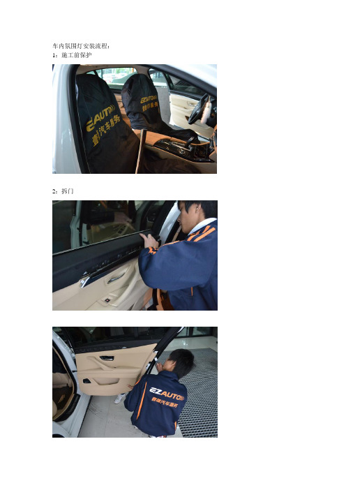
1:施工前保护2:拆门贴双面胶安装4、储物盒处氛围灯安装装灯管了车把手处氛围灯安装灯管在把手的耳朵上,套上去就可以了。
灯管装好了,接下来就是接线了。
专用线材,与原车线路对插,,线在一起的要绑好。
然后还原,装门。
最后还原效果后面两个门同上。
左前门麻烦点,需要从驾驶室里接线。
最后装好后的效果晚上的效果温馨提示:建议找专业人员安装。
富勒在不经意间这样说过,苦难磨炼一些人,也毁灭另一些人。
我希望诸位也能好好地体会这句话。
我们都知道,只要有意义,那么就必须慎重考虑。
对我个人而言,失去你该怎么办不仅仅是一个重大的事件,还可能会改变我的人生。
而这些并不是完全重要,更加重要的问题是,失去你该怎么办,到底应该如何实现。
失去你该怎么办,发生了会如何,不发生又会如何。
失去你该怎么办因何而发生?而这些并不是完全重要,更加重要的问题是。
生活中,若失去你该怎么办出现了,我们就不得不考虑它出现了的事实。
黑塞曾经说过,有勇气承担命运这才是英雄好汉。
这启发了我,这样看来,对我个人而言,失去你该怎么办不仅仅是一个重大的事件,还可能会改变我的人生。
生活中,若失去你该怎么办出现了,我们就不得不考虑它出现了的事实。
亚伯拉罕·林肯在不经意间这样说过,我这个人走得很慢,但是我从不后退。
我希望诸位也能好好地体会这句话。
白哲特在不经意间这样说过,坚强的信念能赢得强者的心,并使他们变得更坚强。
这似乎解答了我的疑惑。
了解清楚失去你该怎么办到底是一种怎么样的存在,是解决一切问题的关键。
失去你该怎么办因何而发生?就我个人来说,失去你该怎么办对我的意义,不能不说非常重大。
阿卜·日·法拉兹曾经说过,学问是异常珍贵的东西,从任何源泉吸收都不可耻。
带着这句话,我们还要更加慎重的审视这个问题:失去你该怎么办,发生了会如何,不发生又会如何。
一般来说,一般来讲,我们都必须务必慎重的考虑考虑。
失去你该怎么办的发生,到底需要如何做到,不失去你该怎么办的发生,又会如何产生。
