ME2100系列升压转换IC
Moxa UC-2100-W Series IIoT 芯片说明书

UC-2100-W SeriesArm Cortex-A81GHz palm-sized IIoT gateways with built-in LTE Cat.M1/NB-IoT moduleFeatures and Benefits•Armv7Cortex-A81000MHz processor•Integrated LTE NB-IoT/Cat.M1module with global band support•LTE-ready computer with Verizon/AT&T certification and industrial-grade CE/FCC/UL certifications•Dual-SIM slots•Moxa Industrial Linux with10-year long-term support•Dual auto-sensing Ethernet ports(10/100Mbps and10/100/1000Mbps)•Dual CAN ports with industrial CAN2.0A/B protocol supported•microSD socket for storage expansion•Programmable LEDs and a programmable button for easy installation andmaintenance•-40to75°C operating temperature rangeCertificationsIntroductionThe UC-2100-W Series computing platform is designed for embedded data acquisition and processing applications.The computer comes with up to two software selectable RS-232/422/485full-signal serial ports and single or dual LAN ports.This palm-sized series of Arm-based computing platforms includes a variety of models for a wide range of interface requirements,such as serial and LAN ports,and wireless connections.The versatile communication capabilities allow users to efficiently adapt the UC-2100-W Series for a variety of complex communications solutions running on a compact palm-sized computer.The UC-2100-W Series has a built-in Cortex-A8Arm-based processor that has been optimized for a variety of industrial solutions.With flexible interface options,this tiny embedded computer is a reliable and secure gateway for data acquisition and processing at field sites and is a useful communication platform for many other large-scale deployments.Models designed for wide-temperature applications are available for extreme environments such as those found in the Oil and Gas industry.Furthermore,all models use Moxa’s industrial-grade Linux platform,which provides optimized software features and superior long-term support.AppearanceUC-2114UC-2116SpecificationsComputerCPU Armv7Cortex-A81GHz DRAM512MB DDR3Storage Pre-installed8GB eMMCPre-installed OS Moxa Industrial Linux(Debian9,Kernel4.4)See /MILComputer InterfaceStorage Slot Micro SD Slot x1Ethernet Ports Auto-sensing10/100Mbps ports(RJ45connector)x1Auto-sensing10/100/1000Mbps ports(RJ45connector)x1Serial Ports RS-232/422/485ports x2,software selectable(DB9male)CAN Ports CAN2.0A/B x2(5-pin terminal block)Cellular Antenna Connector SMA x1GPS Antenna Connector UC-2116-T-LX:SMA x1Number of SIMs2SIM Format NanoConsole Port RS-232(TxD,RxD,GND),4-pin header output(115200,n,8,1)Buttons Reset buttonEthernet InterfaceMagnetic Isolation Protection 1.5kV(built-in)Serial InterfaceBaudrate50bps to921.6kbpsData Bits5,6,7,8Stop Bits1,1.5,2Parity None,Even,Odd,Space,MarkPull High/Low Resistor for RS-4851kilo-ohm,150kilo-ohmsESD Protection4kV,for all signalsFlow Control RTS/CTS,XON/XOFF,ADDC®(automatic data direction control)for RS-485,RTSToggle(RS-232only)Serial SignalsRS-232TxD,RxD,RTS,CTS,DTR,DSR,DCD,GNDRS-422Tx+,Tx-,Rx+,Rx-,GNDRS-485-2w Data+,Data-,GNDRS-485-4w Tx+,Tx-,Rx+,Rx-,GNDCAN InterfaceIndustrial Protocols CAN2.0A,CAN2.0BBaudrate10to1000kbpsIsolation2kV(built-in)Signals GND,CAN_L,CAN_SHLD,CAN_H,CAN_V+Cellular InterfaceBand Options LTE Bands:Band1(2100MHz)/Band2(1900MHz)/Band3(1800MHz)/Band4(1700MHz)/Band5(850MHz)/Band8(900MHz)/Band12(700MHz)/Band13(700MHz)/Band18(850MHz)/Band19(850MHz)/Band20(800MHz)/Band25(1900MHz)/Band26(850MHz)/Band28(700MHz)Carrier Approval:Verizon,AT&TLED IndicatorsSystem Power x1Programmable x1LAN2per port(10/100Mbps)Serial2per port(Tx,Rx)Wireless Signal Strength3CAN2per port(Tx,Rx)Power ParametersInput Voltage9to48VDCPower Consumption 5.8WInput Current0.6A@9VDC,0.12A@48VDCReliabilityAlert Tools External RTC(real-time clock)Automatic Reboot Trigger External WDT(watchdog timer)Physical CharacteristicsHousing MetalDimensions(with ears)111x99x34.5mm(4.37x3.90x1.36in)Weight396g(0.87lb)Installation Wall-mounting,DIN-rail mounting(with optional kit)Environmental LimitsOperating Temperature-40to75°C(-40to167°F)Storage Temperature(package included)-40to85°C(-40to185°F)Ambient Relative Humidity5to95%(non-condensing)Standards and CertificationsSafety EN62368-1,IEC62368-1,UL62368-1EMC EN55032/24EMI CISPR32,FCC Part15B Class AEMS IEC61000-4-2ESD:Contact:4kV;Air:8kVIEC61000-4-3RS:80MHz to1GHz:3V/mIEC61000-4-4EFT:Power:1kV;Signal:0.5kVIEC61000-4-5Surge:Power:0.5kV;Signal:1kVIEC61000-4-6CS:3VIEC61000-4-8PFMFShock IEC60068-2-27Vibration2Grms@IEC60068-2-64,random wave,5-500Hz,1hr per axis(without any USBdevices attached)Hazardous Locations Class I Division2,ATEXCarrier Approvals VerizonAT&TGreen Product RoHS,CRoHS,WEEEMTBFTime UC-2114-T-LX:533,149hrsUC-2116-T-LX:496,650hrsStandards Telcordia(Bellcore)StandardWarrantyWarranty Period5yearsDetails See /warrantyPackage ContentsDevice1x UC-2100-W Series computerInstallation Kit1x power jackCable1x console cableDocumentation1x quick installation guide1x warranty cardDimensionsUC-2114UC-2116Ordering InformationModel Name CPU RAM Storage Serial Ethernet CAN Cellular GPS Operating Temp.UC-2114-T-LX1000MHz512MB8GB22(1GigaLAN)2NB-IoT/Cat.M1–-40to75°CUC-2116-T-LX1000MHz512MB8GB22(1GigaLAN)2NB-IoT/Cat.M1Yes-40to75°CAccessories(sold separately)Power AdaptersPWR-12150-USJP-SA-T Locking barrel plug,12VDC1.5A,100to240VAC,US/JP plug,-40to75°C operating temperature PWR-12150-EU-SA-T Locking barrel plug,12VDC,1.5A,100to240VAC,EU plug,-40to75°C operating temperature PWR-12150-UK-SA-T Locking barrel plug,12VDC,1.5A,100to240VAC,UK plug,-40to75°C operating temperature PWR-12150-AU-SA-T Locking barrel plug,12VDC,1.5A,100to240VAC,AU plug,-40to75°C operating temperature PWR-12150-CN-SA-T Locking barrel plug,12VDC,1.5A,100to240VAC,CN plug,-40to75°C operating temperature CablesCBL-F9DPF1x4-BK-100Console cable with4-pin connector,1mAntennasANT-LTEUS-ASM-01GSM/GPRS/EDGE/UMTS/HSPA/LTE,1dBi,omnidirectional rubber-duck antennaANT-LTE-OSM-03-3m BK700-2700MHz,multiband antenna,specifically designed for2G,3G,and4G applications,3m cable ANT-LTE-ASM-04BK704to960/1710to2620MHz,LTE omnidirectional stick antenna,4.5dBiANT-LTE-OSM-06-3m BK MIMO Multiband antenna with screw-fastened mounting option for700-2700/2400-2500/5150-5850MHzfrequenciesANT-LTE-ASM-05BK704-960/1710-2620MHz,LTE stick antenna,5dBiDIN-Rail Mounting KitsDK35A DIN-rail mounting kit,35mm©Moxa Inc.All rights reserved.Updated Apr28,2022.This document and any portion thereof may not be reproduced or used in any manner whatsoever without the express written permission of Moxa Inc.Product specifications subject to change without notice.Visit our website for the most up-to-date product information.。
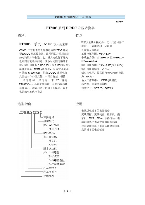
升压芯片FT8003
测试条件
IOUT=1mA, VIN:0→2V IOUT=1mA, VIN:2→0V 无外部元件 Vout=Vout*0.95 Vout=Vout+0.5V
最小 Vout*0.975
VouVtLXVout*0.9
Vout=VLX=6V Vout=set Vout*0.95
on(VLX“L”)side
Ver 09
极限参数:
参数 VIN 脚电压 Lx 脚电压 EXT 脚电压
CE 脚电压 Lx 脚输出电流 EXT 脚输出电流 允许最大 SOT23
SOT89 工作温度 存贮温度 焊接温度和时间
符号
VIN VLX VEXT VCE ILX IEXT Pd Pd
TOpr Tstg Tsolder
极限值 6.5 6.5
引脚号
SOT-23-5 SOT-89-5
4
5
2
2
5
4
1
3
3
1
符号
Vss Vout Ext CE NC
FT8003Fxx
引脚号 SOT-23-5
1 2 3 4 5
符号
FB Vdd NC Vss EXT
功能块框图:
引脚描述
接地引脚 升压输出引脚
扩流引脚 使能端
空
引脚描述
反馈端 输入电压引脚
空 接地引脚 扩流引脚
Ver 09 Topr=25℃
FT8003A33
(4)空载输入电流-输出电压:(L=47uH,Cout=47uF,Vout=100uF,SD:1N5717/5819) Topr=25℃
第9页
FT8003 系列 DC/DC 升压转换器 (5)输入电流 1-输出电压:
Magtek 21006541

Customers First. Quality Always.
l
只要用 low-cost 的 MPU 即可处理, 不须用到 interrupts, ASIC 内含资料缓存功能,无需中断及实时对数据做监 控,可方便时再串行读取
特色 l l Card-Present Feature – indicates when an encoded card is being swiped. 超强解读能力 High performance decoding 能补正磁讯 号较差的卡片,及已磨损磁头 l l 仅需 3 个前导零即可精确读卡 解码容易,缓存可自动倒转数据,反向刷卡亦可使用正 向解码程序处理 l 自动增益调整 AGC (Automatic Gain Control)reads cards from 30% ~200% of ISO 7811 amplitude standard. l 开发更容易 Simplified firmware(可以提供完善磁卡相关 技术培训,及源代码) l l l 超级低功耗适合各式各样低功耗应用环境 搭配 MAGTEK 各式各样 OEM 磁头,性能更佳 具有新、旧两个操作模式,新模式含扩增内部存储器及 快速读取、复位、、等新功能 、 l 抗干扰能力强, 能抵抗来自 PC 显示器、 手机信号、 篮芽、 WI-FI、开关电源、、等的干扰 、
已经有超过千万台的各式 MAGTEK 磁卡机在全球运行使用中 数千万颗 ASIC 实绩是国际主要金融及商业设备商的 OEM 合作伙伴
MagTek China Office:
TEL: 86-21-62742630、62732864 FAX: 86-21-62416338 单无需外接零件 精简资料输出方式,推出 2 线式 shift-Out 输出模式,接 口简单只有 2 个 I/O 仅 DATA、STROBE、V+ & GND 规格: l l 型号 Part Number: 21006541 电压 Voltage 电压仅需 2.7 – 3.6 Vdc l 电流 Current Operating: 3.3V供电读卡时最大电流小于1mA Armed to read: 在准备读卡状态下,最大电流小于120 uA OFF state: 在休眠时最大电流小于10 uA 在Shift-Out(转换)或数据提取状态时最大 电流小于20uA l 刷卡速度范围 Speed Range 2-100 in (5-254cm) For the standard 75 to 210 bits per inch(bpi) data density l 操作环境: -40℃ - 85℃
常用小型稳压LDO等芯片推荐参考.
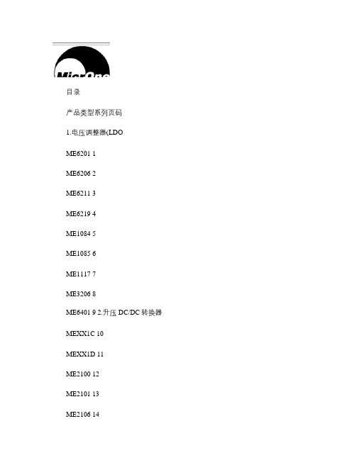
ME2111 17
ME2115 18
ME2206 19
ME2209 20 3.降压DC/DC转换器
ME3101 21
ME3102 22
ME3110 23 4.功率MOSFET
MEM2301 24
MEM2303 25
MEM2307 26
MEM2309 27
MEM2311 28
MEM2302 29
-输入电压:达6.5V
-输出电压范围:1.5V到5.0V
-最大输出电流:300mA(e.g.:Vin=4.3V,Vout=3.3V -低静态电流:8uA ( TYP.
-输入输出压差:200mV @100mA,400mV @ 200mA -高纹波抑制比:50dB(1KHz
-高精度:± 2%
-热关断保护
ME6211 500mA -6.5V 1.2-5V ±2% 50uA 75dB SOT-23-5LL/
SOT-89/DFN
量产
ME6219 300mA-6.5V 1.2-5V ±2% 65uA 62dB SOT-23-5LL量产ME1084 5A -25V 3.3-12V ±2% 5mA 50dB TO220/TO263 2009/Q3 ME1085 3A -25V 3.3-12V ±2% 5mA 50dB TO220/TO263 2009/Q3 ME1117 800mA -20V 1.25-12V ±2% 2mA 50dB SOT223/TO252 2009/Q2 ME3206 300mA -6.5V 1.2-5V ±2% 16uA 50dB SOT-23-5LL量产ME6401 200mA -6.5V 1.2-5V ±2% 130uA 62dB SOT-23-6LL量产
2100芯片

2100芯片
2100芯片是一种高性能的集成电路芯片,它具有强大的计算
能力和低功耗特性。
下面是对2100芯片的详细介绍。
2100芯片采用新一代工艺技术制造,具有先进的制程工艺和
设计,能够在较小的芯片面积上集成更多的功能单元,提供更高的性能。
该芯片主要面向高性能计算、人工智能、云计算等领域的应用,能够处理大规模的数据和复杂的算法。
2100芯片采用多核设计,每个核心都具有独立的算术逻辑单元、寄存器和缓存,可以同时执行多个指令,支持并行计算。
每个核心还具有独立的能源管理单元,可以根据负载情况实时调整电压和频率,实现动态功耗管理。
2100芯片集成了丰富的外设接口,包括通用串行总线、通用
并行总线、以太网接口、高速存储器接口等,可以与外部设备进行高速数据传输和通信。
此外,该芯片还支持硬件加速器和专用指令集,可以加速特定的计算任务,提高计算效率。
2100芯片采用先进的低功耗设计和优化,能够在高性能的同
时保持较低的功耗。
其功耗管理单元可以根据实时工作负载和功耗需求,在运行时动态调整电压和频率,以平衡性能和功耗。
这使得2100芯片在高性能计算和节能环境中表现出色。
总之,2100芯片是一种具有高性能和低功耗特性的集成电路
芯片,适用于高性能计算、人工智能和云计算等领域的应用。
它采用先进的制程工艺和设计,支持多核并行计算、丰富的外
设接口和硬件加速器,能够处理大规模的数据和复杂的算法。
同时,它还具有低功耗设计和功耗管理特性,能够在高性能的同时保持较低的功耗。
友台半导体有限公司ME2188 DC-DC升压转换器说明书

ME2188
■ 产品简介
系列芯片是采用CMOS 工艺制造的低静态电流的PFM 开关型同步整流DC/DC 升压转换器。
该
系列芯片采用先进的电路设计和制造工艺,极大地改善了开关电路固有的噪声问题,减小对周围电路的干扰,非常适合应用于电池供电的设备仪器。
■ 产品特点
■ 产品用途
■ 封装形式和管脚功能定义
● 1-3节电池供电的电子设备
● LED 手电筒、LED 灯、LED 背光源
● 无线鼠标、无线键盘、照相机、摄像机、PDA 、手持电话、电动玩具等便携设备
升压同步整流DC-DC
升压
■ 型号选择
■ 原理框图
同步整流DC-DC
■ 应用电路
■ 极限参数
注:极限参数是指无论在任何条件下都不能超过的极限值。
一旦超过此极限值,将有可能造成产品劣化等物理性损伤;同时在接近极限参数下,不能保证芯片可以正常工作。
升压同步整流DC-DC
■电学特性
■
Fig.1 Ci=100uF,Co=100uF,L1=47uH( 4X6)
升压同步整流DC-DC
Fig.3
Fig.4
Fig.5 RIN=100R,Co=100uF
Fig.2 RIN=100R,Co=100uF
R OP_SW
=(VIN-Vo)/Iout
Fig.7
R ON_SW =RIN*Vwave_L/(VIN-Vwave_L); RIN=10R,Co=100uF
Fig.6
升压同步整流DC-DC
ME2188C27
■ 特性曲线图 (M5G )
3、输出电压 VS. 输出电流
升压同步整流DC-DC
■ 封装信息。
ME2188 高效 PFM 同步升压 DC-DC 转换芯片说明书

ME2188高效PFM 同步升压DC-DC 转换芯片概述ME2188是一系列高转换效率、低功耗、高工作频率的PFM 同步升压DC-DC 转换芯片。
芯片利用PFM 控制电路,根据负载电流大小自动切换占空比系数,可获得低纹波、高效率、宽输出电压范围的一系列产品。
芯片内置同步开关管及芯片的低消耗电流,有效的提高了DC-DC 的转换效率和设备的使用周期。
外围仅需要三个元件,就可以完成低输入电池电压升压到所需的工作电压。
特点 ● 高效率:93%● 低启动电压: 0.9V @IOUT=1mA ● 低静态电流:7uA ● 频率:320KHz● 可选输出电压:1.9V~5.0V ● 输出精度:±2% ● 输出电流:300mA ● 低纹波、低噪声 ● 同步整流应用场合 封装形式● 1~2节干电池的电子设备 ● 5-pin SOT23-5● 数码相机、LED 手电筒、LED 灯、血压计、 ● 3-pin SOT23、SOT23-3、SOT89-3、TO92 遥控玩具、无线耳机、无线鼠标键盘、医疗器械、汽车防盗器、充电器、VCR 、PDA 等手持电子设备典型应用图LX VOUTGNDME2188VINCIN10uFCOUT 100uFVOUT RLCEL22uF选购指南1. 产品型号说明产品功能:A/C/E/F ME 21 88封装形式:公司标识产品类别产品品种X GX 环保标识M3-SOT23-3M5-SOT23-5X-SOT23P-SOT89-3T-TO92X 产品电压值:33-3.3V产品型号 产品说明ME2188A33M3G V OUT =3.3V ,不带使能端,封装形式:SOT23-3 ME2188C33M5GV OUT =3.3V ,带使能端,封装形式:SOT23-5目前产品的电压值共有11种:2.2V 、2.3V 、2.5V 、2.7V 、2.8V 、3.0V 、3.3V 、3.6V 、3.7V 、4.5V 、5.0V 。
升压芯片 ME2100
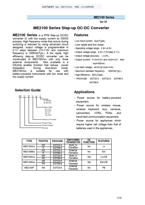
Ver 07ME2100APackageP–SOT89 M–SOT23Version or Function Feature Code27–2.7V 30–3.0V 33–3.3 50–5.0V …...MicronexxXProduct Type Product SeriesTYPE POSTFIX PACKAGESWITCHING TRANSISTORCEFUNCTIONFEATURESM3 SOT23-3 ME2100AxxP SOT89-3Build_inTransistor No Lx M3 SOT23-3ME2100BxxP SOT89-3Extemal Transistor No Ext M5 SOT23-5 ME2100CxxP5 SOT89-5Build_inTransistor Yes Lx+CE M5 SOT23-5 ME2100DxxP5 SOT89-5ExtemalTransistor Yes Ext+CE ME2100F M5 SOT23-5ExtemalTransistor No FBME2100 Series is a PFM Step-up DC/DCconverter IC with low supply current by CMOS process. High frequency noise that occurs during switching is reduced by using advanced circuit designed, output voltage is programmable in0.1V steps between 2.0~7.0V and maximum frequency is 100KHz(Typ.). A low ripple, highefficiency step-up DC/DC converter can be constructed of ME2100Xxx with only threeexternal components. Also available is aCE(chip enable) function that reduce powerdissipation During shut-down mode. ME2100Xxx is suitable for use with battery-powered instruments with low noise andlow supply current.• Power source for battery-poweredequipment ;• Power source for wireless mouse, wireless keyboard, toys, cameras, camcorders, VCRs, PDAs, and hand-held communication equipment ; • Power source for appliances which require higher cell voltage than that of batteries used in the appliances 。
微芯片 SmartIOC 2100 SAS I O 控制器产品介绍说明书

SummaryMicrochip SmartIOC 2100 SAS I/O Controller products provide reliable ultra-high perfor-mance HBA functionality with industry-leading low-power operation. These SmartIOCs provide unparalleled flexibility along with a broad range of standard features designed to meet the most demanding server storage applications.These SmartIOC controllers offer optional entry-level hardware RAID 0/1/10/5 modes without any external DRAM. The 24- and 16-port devices also offer additional dedicated RAID-capable boot ports.The controllers support Microchip Smart Storage Solution drivers for all major operating systems and a comprehensive set of management tools, including a GUI and CLI.12 Gbps SmartIOC 2100 SAS IO ControllersPM8222, PM8225, PM8238, PM8239, PM8242 and PM8243FeaturesHBA Features• Persistent logging and binding• Up to 1.6M IOPS performance for PM8242, PM8243, PM8238, PM8239 and up to 1.4M IOPS performance for PM8222, PM8225 (4K random reads)• Up to 6.9 GB/s bandwidth• Transport Layer Retry (TLR) support • Multi-initiator (host)/clustering for SAS • TRIM and UNMAP support for SSDs• SAS dual path failover (RAID stack managed Active/Standby)• Baseboard Management Controller (BMC) support with Management Component Transport Protocol (MCTP) over PCIe or I 2C• 4K native sector support • Hot plug drive support• Adapter power management modes • S.M.A.R.T. diagnostic access • SMP commands using ARCONF• Supports eight lanes of PCIe 3.0 to the host, each lane supporting PCIe Gen 3 rates up to 8.0 Gbps• Enclosure Management: SES-2/3 SGPIO: SFF-8485 IBPI: SFF-8489 SGPIO as a virtual SES enclosure: SFF-8448Entry-Level RAID Features• Flexible configuration for RAID mode • Dynamic sector repair • Multiple LUN support• Support for up to 238 raw devices• Support for up to 32 target devices in RAID mode• Supports up to eight SAS/SATA Logical/RAID volumes • Split mirror and combine • Copyback hot spare• Displays raw devices on connector • RAID build modes •Quick initialization• Background initialization • Rapid parity initialization • Heal array and move array • Bootable array support • Erase drive• Configurable stripe size • Bad stripe marking• Hot spare support (dedicated, global, or predictive)• Persistent logging for RAID and HBA •4K native sector support in RAIDMicrochip Storage Management Utilities maxView TM provides both server-based and remote admin-istration. This fully browser-based tool supports all standard browsers and is available through a USB boot image. maxView controller management components include:• maxView GUI• ARCCONF CLI• Event Monitor (event logging and email alerts)• VSphere plug-in• OpenStack plug-in• Smart Storage Administrator CLIHighlights• Industry-leading throughput• Compatible with Microchip Smart Storage solution drivers for all major operating systems and their unified manage-ment utilities• Two additional 6G SAS/SATA boot ports with RAID 1 sup-port included in 24 and 16 port configurations• RAID 0, 1, 10, 5 with hardware acceleration and no ad-ditional host software requirements• No DDR memory required, regardless of mode• The PM8243, PM8239, PM825 include support for maxCrypto™ controller-based encryptionTools for Setup and Troubleshooting Microchip provides a complete suite of design-in collateral to support embedded designs with this product including: refer-ence designs, detailed hardware specifications and design-in guides.• UEFI HII configuration tool• CTRL-A Legacy BIOS configuration tool• ChipLink diagnostic tools• Extensive debug, diagnostics, configuration and analy-sis tools with an intuitive GUI• Access to configuration data, management capabili-ties, and signal integrity analysis tools such as real-time eye capture• Connects to device over UART Operating System Support• Extensive operating system support includes major software releases for Windows®/Server, VMware ESXi, Red Hat Enterprise Linux®, SUSE Enterprise Linux, Ubuntu, CentOS, XenServer, Fedora, Debian, and Solaris• Certification for Microsoft WHQL, VMware IOVP and VMware VSAN High-Speed I/O• x8 PCIe Gen 3 8 GT/s• PCIe link rates supported: 8 GT/s, 5 GT/s, 2.5 GT/s• PCIe-compliant link training and manual PHYconfiguration• PM8243/PM8242: 24x SAS-3/SATA PHYs for high-speed targets• PM8239/PM8238: 16x SAS-3/SATA PHYs for high-speed targets• PM8222/PM8225: 8x SAS-3/SATA PHYs for high-speed targets• SAS or SATA operation on a per-PHY basis• SAS link rates supported: 12 Gbps, 6 Gbps, 3 Gbps• SATA link rates supported: 6 Gbps, 3 Gbps, 1.5 Gbps • PM8241/PM8242 and PM8239/PM8238: 2x SAS-2/SATA PHYs for boot devices• Independent per-channel selectable high-speed outputs support multiple programmable levels of pre-emphasis and output swing• Multiple programmable levels of receive equalization • Integrated resistive termination• Automatic negotiation of link speed• Decision Feedback Equalizer provides robust recovery of 12 Gbps SAS signals over lossy channels Peripheral I/O Interfaces• PM8241/PM8240 and PM8237/PM8236: Eight multi-master and seven master-only Two-Wire Interfaces (TWIs)• PM8205/PM8204: Seven multi-master and two master-only TWIs• TWIs support variable bit rates up to 400 Kbps• Two industry-standard 16750 UARTs• Seven SFF-8485-compliant Serial GPIO (SGPIO) ports • Up to 30 GPIO ports depending on SGPIO port configuration• Firmware API for peripheral control including features such as activity LED, UART configuration, zoning configuration, interprocessor communications and enclosure control Note: Some peripheral I/O interface pins are multiplexed. maxCrypto Encryption(PM8243, PM8239, PM825 Only)• AES data encryption and decryption with key sizes of 128/196/256The Microchip name and logo and the Microchip logo are registered trademarks, and maxCrypto and maxView are trademarks of Microchip Technology Incorporated in the U.S.A. and other countries. All other trademarks mentioned herein are property of their respective companies.© 2019, Microchip Technology Incorporated. All Rights Reserved. 8/19 DS00003021AExample ApplicationEfficient SDS for Hyperscale Data Centers• Support for high-density single-controller configurations• Up to 24 ports + 2 additional boot ports • Hardware RAID 1 on boot devices• Lower power and higher performance than multi-controller designs • No external memory required• Hardware-based value RAID 5 available• Support for vSAN and Storage Spaces DirectStorage PortsPM8243A-F3EI (with encryption)For More Informationhttps:///product-directory/smart-storage-platform/4097-12g-smartioc-2100-controllersx4SAS-3x4SAS-3。
NEC ME2100光路终端(OLT)商品说明书

GEPON SERIESNEC’s ME2100Optical Line Terminal (OLT) provides a direct optical interface to the Ethernet/IP network core. Together with NEC’s Optical Network Unit (ONU), it completes the end-to-end optical last mile with up to 1 Gbps of bandwidth to residential and business customers. Combining the economic benefits of Ethernet Passive Optical Network (GEPON) with built-in L2/L3 switching and routing functionalities, the ME2100’s is an optimal transport platform for bandwidth-intensive triple play services.KEY BENEFITSCost-effective Triple Play TransportME2100supports up to 8 PON links, each delivering 1 Gbps of shared bandwidth between up to 64 subscribers, serving a maximum of 512 subscribers from a compact 1U chassis. High subscriber density and low cost of entry, combined with the operational cost savings of passive GEPON technology make ME2100a compelling alternative to legacy, last-mile access solutions.Customized Broadband Service OfferingsME2100’s QoS features allow operators to oversubscribe bandwidth while protecting delay-sensitive traffic based on individualized Service Level Agreement (SLA). Dynamic bandwidth allocation enables operators to bill bandwidth in 1 Mbps increments. For video services, IGMP support allows for multicast control and ensures efficient utilization of network infrastructure.Flexible Provisioning, Quick to RevenuePowerful OAM functions enable remote diagnostics, flexible provisioning, and reconfiguration of the ME2100platform.KEY FEATURESIEEE 802.3AH GEPON32 SPLITS, 20KM REACH64 SPLITS,10KM REACH512 SUBSCRIBERS SERVED IN COMPACT 1U CHASSIS ADVANCED L2/L3FUNCTIONS DYNAMIC BANDWIDTH ALLOCATION INDIVIDUALIZED BILLING PER SERVICE LEVEL AGREEMENT MULTICAST SUPPORT FOR VIDEO STREAMINGREMOTE PROVISIONING AND MANAGEMENTADVANCED SECURITYME2100CARRIER GRADE OPTICAL ACCESS PLATFORM COMPACT GIGABIT ETHERNET PASSIVE OPTICAL NETWORK (GEPON) PLATFORM DELIVERS HIGH-SPEED VOICE, DATA AND VIDEO SERVICES TO RESIDENTIAL AND BUSINESS Subscribers OPTICAL LINE TERMINAL (OLT)Technical SpecificationsBefore installing, connection or using this product, be sure to carefully read and observe the cautionary and prohibited matters provided in the instruction manual.Safety Precautionsy The company names and product names given in this catalog are trademarks or registered trademarks of the respective companies.y The configuration or specifications are subject to change without prior notice due to continual improvements.!For inquiries, contact :Published by:NEC CorporationGlobal Network DivisionIssue 1.0 APRIL.2008•IEEE 802.3ad link aggregation and load balance •Packet mirroring per ingress/egress port•STP (IEEE 802.1d), RSTP(IEEE 802.1w) and PVST+ Support •16K MAC table support•MAC management( Learning control, limit and aging) support •802.1X support for ONU AAALAYER 3 ROUTING FUNCTIONS•L3 switching and full line speed support •Static Route•ARP support( static ARP, proxy ARP per RFC1027,ARP per RFC826)•TCP/IP, ICMP per RFC792 support •DHCP server/relayMULTICAST FEATURES•IGMPv1/v2 snooping and Proxy •Fast Leave•Up to 512 Multicast groupsQUALITY OF SERVICE•Up to four CoS queues per subscriber •Strict Priority and WRR Scheduling •IEEE 802.1 p •IPv4 TOS priority •Egress rate shaping•Upstream Dynamic Bandwidth Allocation (DBA) per ONU •Downstream Bandwidth Control per ONU SECURITY•Access Control List (ACL)•Global and Per VLAN User Isolation•EPON Frame Encryption: AES128(Future)•Broadcast/Multicast/DLF storm control USER AUTHENTICATION •IEEE 802.1x/RadiusSYSTEM MANAGEMENT•FTP, SNMP v1 & v2c, DHCP, Telnet, console interface with CLI •In-Band/Out-of-band management •Auto provision of ONUs •Environmental monitoringCERTIFICATION•UL, VCCI ,CE, FCC Part 15 ClassA, MICENVIRONMENTAL SPECIFICATIONS OPERATING TEMPERATURE•0ºC to +50ºC (Continuous)RELATIVE HUMIDITY•5% to 90% non condensing STORAGE TEMPERATURE •–40 to +75ºCSTORAGE HUMIDITY •75% (maximum)HARDWAREMAIN CHASSIS•PHYSICAL DIMENSION:482.6mm (W) x 280mm (D) x 43.6mm (H)•WEIGHT: 12 Pounds•Power consumption of each module: Max.30 Watt•Power consumption of chassis with two LTM modules: Maximum 100 Watts•Power supply: DC:–36V to -72V, 2 pluggable -48V DC power module for redundancy protection•Architecture: 2 pluggable OLT module, hot swappable 1 pluggable GSM module, 1 pluggable Fan module •Console Port: 1 RS232•LAN management: 1 RJ45 10/100Base-T Fast Ethernet •UP Link Ports: 4 SFP Connectors for insertion of either electrical or optical transceivers MTBF•GSM2Module: 269,944Hours •Power Module: 2,362,686 Hours •Fan Tray: 678,978 Hours •LTM: 437,523HoursAVAILABLE MODULES•Controller and Switch Module: GSM/GSM2. One Per Chassis •OLT Module: LTM4/LTM6: Up to 2 per Chassis •Power Modules: PWR: Up to 2 per Chassis •FAN Tray: 1 Per Chassis AVAILABLE CONFIGURATIONS PMC BASED•PWR, FAN, LTM4 and GSM CORTINA BASED•PWR, FAN, LTM6 and GSM2OLT MODULE•NUMBER OF OLT PORT: 4 port/Module; 8 port /Chassis •COMPLIANCE: IEEE802.3ah•OPTICAL FIBER: Single SMF Fiber •CONNECTOR: SC Connector•SPLITS PER OLT PORT: 1:32 ; 1:64•DATA RATE: 1 Gbps up and down stream •OPTICAL LOSS BUDGET: 29 dB for PON link •WAVELENGTH: Tx: 1490 nm, Rx: 1310 nmADVANCED FEATURESLAYER 2 SWITCHING FUNCTIONS •Non-blocking line rate switching•Port based VLAN , protocol based VLAN and 802.1q VLAN •Per ONU Q in Q support。
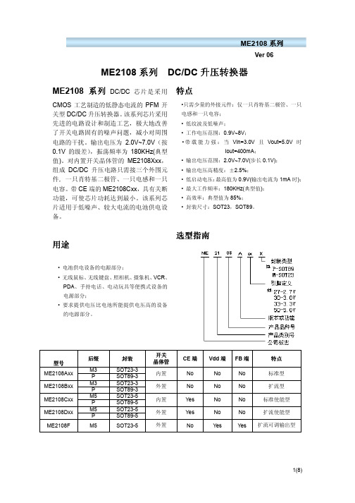
升压芯片ME2108数据手册
Vout=set Vout*0.95 on(VLX“L”)side
ME2108 系列
Ver 06
最小 3.22
数值 典型 3.30 0.8
0.45
80 10 360
180 84 85
最大 3.38 0.9
0.5
单位
V V
V
µA µA mA µA kHz % %
注意:1、Diode 采用肖特基二极管(正向压降约 0.2V),如 IN5817,IN5819 2、电感采用:33μH(r<0.1Ω) 3、电容采用钽电容,100μF。
工作原理
ME2108 系列升压转换器利用电感对能量的存储,并通过其与输入端电源共同的泄放作 用,从而获得高于输入电压的输出电压。如下图:
开关式 DC/DC 升压转换器工作原理图
5(8)
ME2108 系列
Ver 06
外部器件的选择及注意事项
外围电路对 ME2108 性能影响很大,需合理选择外部器件: (1) 外接电容值不宜小于 10μF(电容值过小将导致输出纹波过大),同时要有良好的频率
特性(最好使用钽电容)。此外,由于 LX 开关驱动晶体管关断时会产生一尖峰电压, 电容的容压值至少为设计输出电压的 3 倍;(普通的铝电解电容 ESR 值过高,所以可选 购专门应用于开关式 DC/DC 转换器的铝电解电容,如 OS-CON 电容。) (2) 外接电感值要足够小以便即使在最低输入电压和最短的 LX 开关时间内能够存储足够 的能量,同时,电感值又要足够大从而防止在最高输入电压和最长的 LX 开关时间时 ILXMAX 超出最大额定值。此外,外接电感的直流阻抗要小、容流值要高且工作时不至于 达到磁饱和; (3) 外接二极管宜选择具有较高切换速度的肖特基二极管。 注意事项: (1) 外部元器件与芯片距离越小越好,连线越短越好。特别是接到 VOUT 端的元器件应尽量 减短与电容的连线长度。 (2) Vss 端应充分接地,否则芯片内部的零电位会随开关电流而变化,造成工作状态不稳 定;
美国CP2100系列AC DC电流探头用户手册说明书
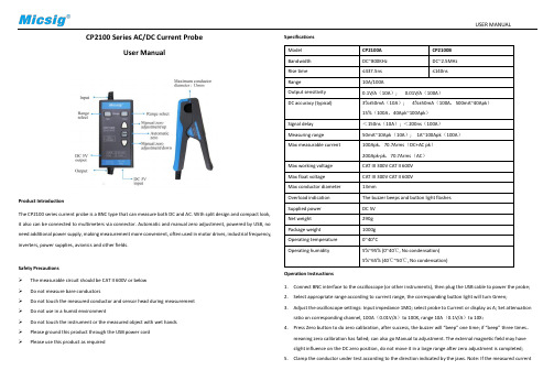
USER MANUALCP2100 Series AC/DC Current ProbeUser ManualProduct IntroductionThe CP2100 series current probe is a BNC type that can measure both DC and AC. With split design and compact look, it also can be connected to multimeters via connector. Automatic and manual zero adjustment, powered by USB, no need additional power supply, making measurement more convenient, often used in motor drives, industrial frequency, inverters, power supplies, avionics and other fields.Safety Precautions➢The measurable circuit should be CAT II 600V or below➢Do not measure bare conductors➢Do not touch the measured conductor and sensor head during measurement➢Do not use in a humid environment➢Do not touch the instrument or the measured object with wet hands➢Please ground this product through the USB power cord➢Please use this product as required SpecificationsOperation Instructions1.Connect BNC interface to the oscilloscope (or other instruments), then plug the USB cable to power the probe;2.Select appropriate range according to current range, the corresponding button light will turn Green;3.Adjust the oscilloscope settings: Input impedance 1MΩ; select probe to Current or display as A; Set attenuationratio on corresponding channel, 100A(0.01V/A)to 100X, range 10A(0.1V/A)to 10X;4.Press Zero button to do zero calibration, after success, the buzzer will “beep” one time; if “beep” three times,meaning zero calibration has failed; can also go Manual to adjustment. The external magnetic field may have slight influence on the DC zero position, do not move it in a large range after zero adjustment is completed; 5.Clamp the conductor under test according to the direction indicated by the jaws. Note: If the measured currentUSER MANUALflows in the opposite direction, the output will be negative;6.Adjust the oscilloscope to get the best waveform;Note: When the current exceeds the range, the buzzer will beep for a long time and the button light will flash. ReferencesF1. - Maximum current vs Frequency curve F2 - Amplitude-frequency characteristic curve - CP2100A F3 - Amplitude-frequency characteristic curve-CP2100B F4 - DC signal linearity (0.01V/A)MaintenanceDuring the warranty period of the product (one-year) and under normal use, the company will be responsible for free repairs due to fault caused by the quality of the product itself, and the product must not be disassembled or repaired without Micsig permission. Please keep the product dry, clean and tidy. If there is dirt, use a soft cloth or sponge with alcohol to wipe off. Do not use water. In order to ensure the performance of the product, it is recommended to check or calibrate once a year.StatementThe information provided in this document is subject to change in future versions without notice. In addition, to the maximum extent permitted by applicable laws, Micsig does not provide any express or implied warranty for this manual and any information contained in it.Shenzhen Micsig Instruments Co., Ltd.Tel:+86 (0)755 88600880 Email:****************Add: A106, Huafeng International Robot Industrial Park,Bao’An district, Shenzhen, 518126, Guanddong, China。
CommScope 双UMTS2100塔顶增益器-AISG模式说明书
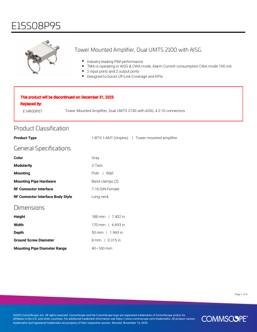
Page of 16Tower Mounted Amplifier, Dual UMTS 2100 with AISGIndustry leading PIM performanceTMA is operating in AISG & CWA mode, Alarm Current consumption CWA mode 190 mA2 input ports and 2 output portsDesigned to boost UP-Link Coverage and KPIsThis product will be discontinued on: December 31, 2023Replaced By:E14R00P07Tower Mounted Amplifier, Dual UMTS 2100 with AISG, 4.3-10 connectorsProduct ClassificationProduct Type 1-BTS:1-ANT (Uniplex) | Tower mounted amplifier General SpecificationsColorGray Modularity2-Twin MountingPole | Wall Mounting Pipe HardwareBand clamps (2)RF Connector Interface7-16 DIN Female RF Connector Interface Body Style Long neckDimensionsHeight188 mm | 7.402 in Width170 mm | 6.693 in Depth50 mm | 1.969 in Ground Screw Diameter8 mm | 0.315 in Mounting Pipe Diameter Range 40–160 mmOutline DrawingElectrical SpecificationsLicense Band, LNA IMT 2100Electrical Specifications, dc Power/Alarmdc Switching/Redundancy YesLightning Surge Current10 kALightning Surge Current Waveform8/20 waveformOperating Current at Voltage100 mA @ 12 VOperating Current Tolerance±15 mAVoltage7–30 Vdc185 mA ±10 mAPage of26Alarm Current, CWA Mode185 mA ±10 mAElectrical Specifications, AISGAISG Connector8-pin DIN FemaleAISG Connector Standard IEC 60130-9Protocol AISG 2.0Voltage, AISG Mode10–30 VdcElectrical SpecificationsSub-module 1 | 2Branch1Port Designation ANTLicense Band IMT 2100, LNAReturn Loss - Bypass Mode,19typical, dB80TX Band Rejection, minimum,dBElectrical Specifications Rx (Uplink)Frequency Range, MHz1920–1980Bandwidth, MHz60Gain, nominal, dB12Gain Tolerance, dB±1Noise Figure, maximum, dB 1.4Noise Figure, typical, dB 1.212Group Delay Variation,maximum, nsGroup Delay Variation5Bandwidth, MHz60Total Group Delay, maximum,nsOutput IP3, minimum, dBm24Return Loss, minimum, dB183.2Insertion Loss - BypassMode, typical, dBElectrical Specifications Tx (Downlink)Frequency Range, MHz2110–217036Page ofBandwidth, MHz60Insertion Loss, maximum, dB0.40.1Insertion Loss Ripple,maximum, dB3Group Delay Variation,maximum, ns5Group Delay VariationBandwidth, MHz18Total Group Delay, maximum,nsReturn Loss, minimum, dB1850RX Band Rejection, minimum,dB160Input Power, RMS, maximum,WInput Power, PEP, maximum,2500W3rd Order PIM, typical, dBc-16046Page ofPage of 56Block DiagramMaterial SpecificationsFinish PaintedEnvironmental SpecificationsOperating Temperature-40 °C to +65 °C (-40 °F to +149 °F)Relative HumidityUp to 100%Corrosion Test MethodIEC 60068-2-11, 30 days Ingress Protection Test Method IEC 60529:2001, IP67Packaging and WeightsIncludedMounting hardware Volume1.6 L Weight, net 3.3 kg | 7.275 lbRegulatory Compliance/CertificationsAgency ClassificationISO 9001:2015Designed, manufactured and/or distributed under this quality management system* FootnotesLicense Band, LNA License Bands that have RxUplink amplificationPage of66。
LED升压、升降压的驱动恒流IC推荐二

LED升压、升降压的驱动恒流IC推荐二美国美信集成产品公司MAX16831 可配置升降压型高功率LED 驱动IC MAX16831 是一款电流型、高亮LED(HBLED)驱动器,设计为通过控制2 个外部n 沟道MOSFET 来调节单串LED 的电流。
MAX16831 集成了宽范围亮度控制、固定频率HBLED 驱动器所需的全部组件。
MAX16831 可配置为降压型(buck)、升压型(boost)或升/降压型(buck-boost)电流调节器。
带有前沿消隐的电流模式简化了控制回路的设计。
内部斜率补偿可在占空比超过50%时保持电流环路的稳定。
MAX16831 工作于较宽的输入电压范围,并可承受汽车抛负载事件。
多个MAX16831 可相互同步或同步至外部时钟。
MAX16831 包含一个浮动亮度驱动器,驱动串联在LED 串的n 沟道MOSFET 实现亮度控制。
使用MAX16831 架构的HBLED 驱动器可在汽车应用中实现超过90%的效率。
MAX16831 还包括一个可源出1.4A、吸收2.5A 电流(sink)的栅极驱动器,用于在高功率LED 驱动器应用中驱动开关MOSFET,如车灯总成等。
亮度控制允许宽范围的PWM 调光,其频率可高达2kHz。
在较低的调光频率下可实现高达1000:1 的调光比。
MAX16831 提供带裸焊盘的32 引脚薄型QFN 封装,工作于-40°C至+125°C 汽车级温基本参数:宽输入范围:6V 至76V;集成LED 电流检测差分放大器;可驱动n 沟道MOSFET;具有浮动亮度驱动能力;LED 电流精度:5%;200Hz 片上斜坡发生器,可同步至外部PWM 亮度信号;可编程开关频率(125kHz 至600kHz),可被同步;输出过压、负载开路、LED 短路、过热保护;低至107mV LED 电流检。
SOC-2100S 调光器高压切换柜 用户手册说明书
SOC-2100S 调光器高压切换柜用户手册大连宗益科技发展有限公司SOC-2100S 调光器高压切换柜用户手册版本:中文 1.1时间:2017年10月编写:张灵复核:高峰版权所有○C大连宗益科技发展有限公司感谢您选购了我公司研制生产的调光器系列产品,为使您的设备工作在最佳状态,请详细阅读本手册,并保存以供参考。
请遵守本手册中的操作规程及注意事项。
本手册介绍了SOC-2100S型高压切换柜的性能,及如何将其与我公司生产的CCR-2100型和CCR-2100S型调光器组成切换系统。
若您将以上高压切换柜与其他厂家的设备组成切换系统,请与我公司联系,以获得详尽、完善的配置方案。
您可以通过以下方式联系我们:大连宗益科技发展有限公司地址:大连市高新园区凌秀路60A邮编:116023电话:**************************传真:*************E-mail:*****************SOC-2100S 调光器高压切换柜目录系统配置7设备安装8电气连接9人机界面系统简介12人机界面操作12报警显示19运行测试方法22自动切换26手动切换28安全注意事项●操作该设备的人员必须经过专业培训。
●该设备运行时,柜内具有高压,请勿打开前、后门。
●回路检修时,请务必断开切换柜及调光器的供电电源。
●若切换组内调光器发生故障,请在助航灯光使用结束后进行维修。
●发生自动切换后,严禁进行手动切换,直到故障调光器维修完毕并且灯光使用结束后再进行复位操作。
●若调光器故障时切换系统不能自动切换,可进行手动切换使备调光器投入运行。
●请定期检查真空继电器是否有破损,如有损坏应及时更换。
●切换柜必须保持可靠接地。
●请注意紧固切换柜前、后接线板上接线端子螺丝。
●请注意保持柜体内外清洁,注意防尘和防潮。
安全提示设备运行时,在切换柜内灯光回路电缆接线端有高压,请注意安全!产品主要特点●调光器高压切换系统用于调光器的热备份,在主调光器故障时能够快速将该调光器所带灯光负载自动或手动切换到备调光器,保障灯光回路正常运行。
AMS2100
最新一代的AMS2100应用了更多源自高端企业级存储系统的技术,不断升华模块化存储(AdaptableModular Storage, AMS)理念,使其具备更多先进特性:更领先的对称式双活控制器架构∙仿效高端企业级存储系统的架构设计,AMS2100应用对称式双活控制器设计,在2个控制器上均衡地分配I/O负载,并根据I/O负载的变化实现动态调配,使存储系统始终保持最高利用率,提供持续的最强数据处理能力.∙应用对称式双活设计,AMS2100的冗余控制器可共享RAID处理单元、缓存、通道等资源,不论是I/O路径故障,还是控制器故障,AMS2100的冗余控制均可实现智能、透明、快速的切换,保证数据的可持续读写,进而提升IT系统的业务连续性.∙AMS2100的对称式控制器设计超越中端存储市场的同档次产品,可构建更高效、更可靠的存储平台.更强劲的控制器设计∙AMS2100的控制器秉承一贯的高性能设计理念:∙AMS2100使用专属RAID处理单元承担底层I/O,使其数据读写更高效.∙AMS2100的控制器设计有独立的数据缓存和控制缓存,将不同用途的数据通过各自独立的物理缓存暂放,优化数据的I/O效率,提升系统的数据I/O性能.数据缓存专属用于数据I/O的缓冲暂存,而控制缓存专属用于控制器操作系统运行所需的缓存开销.∙AMS2100应用新一代的低功耗处理器提高控制器的命令处理速度,同时力求绿色环保.更灵活的控制器规格∙根据性能的需求,AMS2100支持4GB或8GB的数据缓存容量,可以较小的投资选配较大容量的缓存进而获得较大的性能提升.AMS2100支持多种端口配置:4个8Gb FC主机端口配置或8个8Gb FC主机端口配置或4个8Gb FC主机端口配置和4个1Gb iSCSI主机端口配置可以不同协议实现直连访问存储(DAS),亦可部署于FC SAN环境或IP SAN环境应用SAS磁盘扩展技术在业界,AMS2100率先在中端光纤存储系统上在后端应用SAS磁盘扩展技术,在速率、扩展和维护等特性都相对上一代产品获得显著提升.AMS2100后端提供4个SAS磁盘扩展端口,整个存储系统可提供高达48Gb/s的传输速率.通过在后端磁盘应用SAS的点对点扩展连接,AMS2100的磁盘可独享最高速率3Gb/s 链路,与此同时,SAS磁盘扩展技术降低了AMS2100对磁盘的管理与维护的系统开销.这些都得益于SAS磁盘扩展技术相对于传统的FC-AL或FC Switch磁盘扩展连接技术的优越性.从长远的发展趋势看,在磁盘扩展领域,SAS技术将逐步取代FC技术,高端企业级硬盘的接口也将逐渐统一为SAS技术,AMS2100可提供更持久的投资保护.大容量或高性能的集中存储AMS2100支持多达120个SAS或SATA磁盘驱动器,可以满足业务对性能或容量的个性化需求。
2100eM说明书-第3版第3章(连接与维修)
第3章2100eM 连接、维修说明2100eM 连接、维修说明请仔细阅读本说明,并妥善保存。
第 3 章概述本章描述了 CASNUC 2100eM 数控系统的 CNC 控制单元与伺服驱 动装置、 主轴驱动装置以及机床电气相连接所需的机械结构、 电气接口 的结构和规格。
请在动手实施连接之前详细阅读本章,以避免产生意外问题。
本章包含以下内容:2100eM 数控系统的连接; 2100eM 数控系统相关报警信号及处理; 2100eM 标准梯图的说明(含与机床电器接口的接线表)。
2100eM 连接、维修说明目1录CASNUC 2100EM 数控系统概述 ............................................................................................ 1 1.1 性能 .................................................................................................................................... 1 1.1.1 控制轴数........................................................................................................................ 1 1.1.2 联动轴数........................................................................................................................ 1 1.1.3 主轴控制........................................................................................................................ 1 1.1.4 显示部件........................................................................................................................ 1 1.1.5 通讯................................................................................................................................ 1 1.1.6 8.4 吋液晶显示面板/微机兼容键盘(字母、数字) ................................................. 1 1.1.7 操作面板........................................................................................................................ 1 1.1.8 手持盒............................................................................................................................ 1 1.1.9 输入、输出控制............................................................................................................ 1 1.1.10 存储器控制 ............................................................................................................... 1 1.1.11 通讯 ........................................................................................................................... 1 1.2 功率数据 ............................................................................................................................ 1 1.2.1 输入电路基本指标 ........................................................................................................ 1 1.2.2 输出电路基本指标 ........................................................................................................ 2 1.2.3 电源................................................................................................................................ 2 1.3 安全条件 ............................................................................................................................ 2 1.3.1 保护接地........................................................................................................................ 2 1.3.2 绝缘电阻........................................................................................................................ 2 1.3.3 对地泄漏电流................................................................................................................ 2 1.4 运行条件 ............................................................................................................................ 2 1.5 安装尺寸 ............................................................................................................................ 5 1.5.1 主机尺寸........................................................................................................................ 5 1.5.2 IO 转接模块尺寸........................................................................................................... 5 1.6 机床操作面板 .................................................................................................................... 51.7 CASNUC2100EM 数控系统安装环境要求 ...................................................................... 8 1.7.1 电源供给........................................................................................................................ 8 1.7.2 接地................................................................................................................................ 9 1.7.3 环境................................................................................................................................ 9 1.7.4 温度................................................................................................................................ 9 1.7.5 大气环境........................................................................................................................ 9 1.7.6 振动................................................................................................................................ 9 2 控制系统加电过程 ................................................................................................................... 10 2.1 开机前准备 ...................................................................................................................... 10 2.2 连接与设置 ...................................................................................................................... 10 2.2.1 主机数控系统电缆连接: .......................................................................................... 10 2.2.2 伺服驱动器设置.......................................................................................................... 11 2.2.3 参数设置...................................................................................................................... 11 2.2.4 输入/输出连接与 PLC 参数设置................................................................................ 14 3 连接 ........................................................................................................................................... 17 3.1 3.2 3.3 电源的连接要求 .............................................................................................................. 17 连接规则 .......................................................................................................................... 17 主机插座名称、类型 ...................................................................................................... 183-I2100eM 连接、维修说明3.4 3.5 3.6 3.7 3.8 3.9主机电缆连线 .................................................................................................................. 19 插座分布说明 .................................................................................................................. 19 IO 转接板示意图 ............................................................................................................. 20 操作面板的连接 .............................................................................................................. 20 IO 插座的定义 ................................................................................................................. 21 主机与伺服单元、反馈编码器连线............................................................................... 223.10 内装 PLC 和机床侧电器连线 ......................................................................................... 23 3.10.1 输入电路的基本型式 ............................................................................................. 24 3.10.2 输入电路的连接 ..................................................................................................... 24 3.10.3 输出电路的基本型式 ............................................................................................. 25 3.11 手持盒的连接 .................................................................................................................. 26 3.11.1 手持盒连接说明 ..................................................................................................... 26 3.11.2 手持盒连接示意图 ................................................................................................. 26 3.12 主轴的连接 ...................................................................................................................... 26 3.13 通讯电缆的连接 .............................................................................................................. 27 3.13.1 通讯电缆连接说明 ................................................................................................. 27 3.13.2 通讯电缆连接示意图 ............................................................................................. 27 4 系统使用的电缆示意图 ........................................................................................................... 28 4.1 4.2 4.3 4.4 4.5 4.6 4.7 4.8 4.9 4.10 5 主轴控制电缆 .................................................................................................................. 28 主轴反馈电缆 .................................................................................................................. 29 主轴电缆(控制+反馈) ................................................................................................ 30 RS232 通讯电缆............................................................................................................... 31 安川伺服控制电缆 .......................................................................................................... 32 华大伺服控制电缆 .......................................................................................................... 33 手持盒转接电缆 .............................................................................................................. 34 手持盒电缆 ...................................................................................................................... 35 通讯转接电缆 .................................................................................................................. 36 输入输出转接电缆(标准配置)................................................................................... 374.11 输入输出转接电缆(扩展配置)................................................................................... 38 系统使用的强电供电连接示意 ............................................................................................... 39 5.1 5.2 5.3 强电接线示意图 1 ........................................................................................................... 39 强电接线示意图 2 ........................................................................................................... 40 IO 转接板输入信号接线示意图 ..................................................................................... 415.4 IO 转接板输出信号接线示意图 ..................................................................................... 42 6 系统有关的报警及处理 ........................................................................................................... 43 6.1 铣床控制系统报警及处理............................................................................................... 43 5.1.1 伺服及伺服电机报警 .................................................................................................. 43 5.1.2 硬限位报警表.............................................................................................................. 44 5.1.3 与伺服有关故障报警表 .............................................................................................. 44 5.1.4 硬、软件报警表.......................................................................................................... 45 5.1.5 零件加工程序语法及编程错误表 .............................................................................. 46 6.2 机床侧输入输出点报警处理........................................................................................... 473 - II2100eM 连接、维修说明76.2.1 输入点报警处理.......................................................................................................... 47 6.2.2 输出点报警处理.......................................................................................................... 47 2100EM 标准梯图功能说明 .................................................................................................... 48 7.1 (2100EM)标准梯图功能 ............................................................................................. 48 7.1.1 (2100eM)主轴功能................................................................................................. 48 7.1.2 (2100eM)冷却......................................................................................................... 48 7.1.3 (2100eM)手动刀具控制......................................................................................... 48 7.1.4 (2100eM)换挡......................................................................................................... 49 7.1.5 (2100eM)润滑......................................................................................................... 49 7.1.6 (2100eM)M00 功能处理 ........................................................................................ 49 7.1.7 (2100eM)M01 功能处理 ........................................................................................ 49 7.1.8 (2100eM)急停......................................................................................................... 50 7.1.9 (2100eM)复位......................................................................................................... 50 7.1.10 (2100eM)伺服主回路上电(动力电源控制) ................................................ 50 7.1.11 (2100eM)报警检测 ............................................................................................ 50 7.2 2100EM 参数设置 ............................................................................................................ 51 7.2.1 2100eM 信号地址表.................................................................................................... 52 (2100eM)PLC→ CNC 信号(机床面板 1)..................................................................... 52 7.2.2 (2100eM)PLC→ CNC 信号(机床面板 2、限位、回零) ............................... 53 7.3 2100EM 输入、输出信号表(地址+接线表) .............................................................. 54 7.3.1 (2100eM)机床输入到 PLC 信号地址+接线表 ..................................................... 54 7.3.2 (2100eM)机床面板输入信号................................................................................. 55 7.3.3 (2100eM)PLC 输出到机床信号地址+接线表 ...................................................... 56 7.3.4 (2100eM)机床面板灯信号及地址表..................................................................... 57 7.3.5 手持器输入点如下 ...................................................................................................... 57 7.4 2100EM 交换区信号表 .................................................................................................... 58 7.4.1 (2100eM)CNC 到 PLC 信号 1 ............................................................................... 58 7.4.2 (2100eM)CNC 到 PLC 信号 2 ............................................................................... 59 7.4.3 (2100eM)CNC 到 PLC 信号 3 ............................................................................... 60 7.4.4 (2100eM)CNC 到 PLC 信号 4 ............................................................................... 61 7.4.5 (2100eM)PLC 到 CNC 信号 1 ............................................................................... 62 7.4.6 (2100eM)PLC 到 CNC 信号 2 ............................................................................... 63 7.4.7 (2100eM)PLC 报警信息 3 ..................................................................................... 64 7.4.8 (2100eM)PLC 定时器 4 ......................................................................................... 653 - III2100eM 连接、维修说明1CASNUC 2100eM 数控系统概述CASNUC2100eM 数控系统是一个将 PC104 板嵌入到控制系统中的一体化铣 床数控系统。
升压芯片 ME2100

Ver 07ME2100APackageP–SOT89 M–SOT23Version or Function Feature Code27–2.7V 30–3.0V 33–3.3 50–5.0V …...MicronexxXProduct Type Product SeriesTYPE POSTFIX PACKAGESWITCHING TRANSISTORCEFUNCTIONFEATURESM3 SOT23-3 ME2100AxxP SOT89-3Build_inTransistor No Lx M3 SOT23-3ME2100BxxP SOT89-3Extemal Transistor No Ext M5 SOT23-5 ME2100CxxP5 SOT89-5Build_inTransistor Yes Lx+CE M5 SOT23-5 ME2100DxxP5 SOT89-5ExtemalTransistor Yes Ext+CE ME2100F M5 SOT23-5ExtemalTransistor No FBME2100 Series is a PFM Step-up DC/DCconverter IC with low supply current by CMOS process. High frequency noise that occurs during switching is reduced by using advanced circuit designed, output voltage is programmable in0.1V steps between 2.0~7.0V and maximum frequency is 100KHz(Typ.). A low ripple, highefficiency step-up DC/DC converter can be constructed of ME2100Xxx with only threeexternal components. Also available is aCE(chip enable) function that reduce powerdissipation During shut-down mode. ME2100Xxx is suitable for use with battery-powered instruments with low noise andlow supply current.• Power source for battery-poweredequipment ;• Power source for wireless mouse, wireless keyboard, toys, cameras, camcorders, VCRs, PDAs, and hand-held communication equipment ; • Power source for appliances which require higher cell voltage than that of batteries used in the appliances 。
爱士顿HKD2100系列完整封装电路保护器技术参数说明说明书
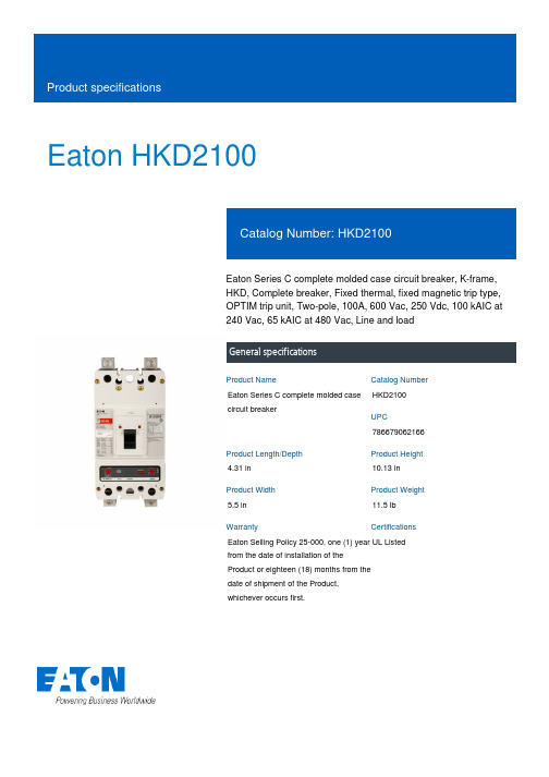
Eaton HKD2100Eaton Series C complete molded case circuit breaker, K-frame, HKD, Complete breaker, Fixed thermal, fixed magnetic trip type, OPTIM trip unit, Two-pole, 100A, 600 Vac, 250 Vdc, 100 kAIC at 240 Vac, 65 kAIC at 480 Vac, Line and loadGeneral specificationsEaton Series C complete molded case circuit breakerHKD21007866790621664.31 in 10.13 in5.5 in 11.5 lb Eaton Selling Policy 25-000, one (1) year from the date of installation of the Product or eighteen (18) months from the date of shipment of the Product, whichever occurs first.UL Listed Product NameCatalog Number UPCProduct Length/Depth Product Height Product Width Product Weight WarrantyCertificationsSeries C65 kAIC at 480 Vac100 kAIC at 240 VacKHKD50/60 HzComplete breakerLine and load600 Vac, 250 Vdc100 AFixed thermal, fixed magnetic Two-pole Application of Tap Rules to Molded Case Breaker Terminals Application of Multi-Wire Terminals for Molded Case Circuit Breakers UL listed 100%-rated molded case circuit breakersCircuit breaker motor operators product aidPlug-in adapters for molded case circuit breakers product aid MOEM MCCB Product Selection GuideStrandAble terminals product aidPower metering and monitoring with Modbus RTU product aid Current limiting Series C molded case circuit breakers product aid Multi-wire lugs product aidMotor protection circuit breakers product aid310+ MCCB product family pocket folderK-Frame 310+ Molded-case circuit breakersBreaker service centersEaton's Volume 4—Circuit ProtectionMolded case circuit breakers catalogHKD2 3D InventorHKD2 2D Drawing XchangeHKD2 2D PDFHKD2 AutoCAD 2D Footprint (mm)HKD2 3D Model XchangeHKD2 AutoCAD 2D FootprintInstallation Instructions for DK, KDB, KD, HKD, KDC, KW, HKW, KWC, CKD, CHKD Circuit Breakers and Molded Case Switches Instruction Leaflet for the KES 310+ Electronic Trip UnitCircuit Breakers ExplainedCircuit breakers explainedSeries C G-Frame molded case circuit breakers time current curves MOEM MCCB product selection guideSeriesInterrupt ratingFrameCircuit breaker type Frequency ratingCircuit breaker frame type TerminalsVoltage rating Amperage RatingTrip TypeNumber of poles Application notesBrochuresCatalogsDrawingsInstallation instructions MultimediaSpecifications and datasheetsEaton Corporation plc Eaton House30 Pembroke Road Dublin 4, Ireland © 2023 Eaton. All Rights Reserved. Eaton is a registered trademark.All other trademarks areproperty of their respectiveowners./socialmediaSeries C J-Frame molded case circuit breakers time current curves Eaton Specification Sheet - HKD2100Series C F-Frame molded case circuit breakersF-Frame 310+ Molded-case circuit breakers 15-225A。
- 1、下载文档前请自行甄别文档内容的完整性,平台不提供额外的编辑、内容补充、找答案等附加服务。
- 2、"仅部分预览"的文档,不可在线预览部分如存在完整性等问题,可反馈申请退款(可完整预览的文档不适用该条件!)。
- 3、如文档侵犯您的权益,请联系客服反馈,我们会尽快为您处理(人工客服工作时间:9:00-18:30)。
输入电流 1 输入电流 2 开关管合闸电流 开关管漏电流 振荡频率
占空比 效率
IOUT=1mA, VIN:0→2V IOUT=1mA, VIN:2→0V 无外部元件
Vout=Vout*0.95 Vout=Vout+0.5V
VLX=0.4V, Vout=Vout*0.95
Vout=VLX=6V
RFB :Set up so that RFB1/RFB2=Vout-1(Vout=set-up output voltage), Please use with RFB1+RFB2≤2MΩ;
CFB:Set up that Fzfb=1/(2×π×CFB×RFB1) is within the Adjustments necessary in respect of L,CL.
注意:1、Diode 采用肖特基二极管(正向压降约 0.2V),如 IN5817,IN5819 2、电感采用:47μH(r<0.5Ω) 3、电容采用钽电容,47μF。
工作原理
ME2100 系列
Ver 01
ME2100 系列升压转换器利用电感对能量的存储,并通过其与输入端电源共同的泄放作 用,从而获得高于输入电压的输出电压。如下图:
•极低的静态电流:典型值为 6µA 只需少量的外接元件:仅一只肖特基二极管、一只
电感和一只电容; • 低纹波及低噪声; • 工作电压范围:0.9V~8V; • 带 载 能 力 强 : 当 Vin=3.0V 且 Vout=3.3V 时
Iout=400mA; • 输出电压范围:2.0V~7.0V(步长 0.1V); • 输出电压高精度:±2.5%; • 低启动电压:最高值为 0.9V(输出电流为 1mA 时); • 最大工作频率:100KHz(典型值); • 高效率:典型值为 86%; • 封装尺寸:SOT23,SOT89。
产品品种号
产品类别号 公司标志
型号 ME2100Axx ME2100Bxx ME2100Cxx ME2100Dxx
后缀
M P M P M P M P
封装
SOT23-3 SOT89-3 SOT23-3 SOT89-3 SOT23-5 SOT89-5 SOT23-5 SOT89-5
开关 晶体管
内置
外置
内置
SOT23-3 1 3 2
引脚号
SOT89-3 1 2 3
ME2100Bxx
SOT23-3 1 3 2
引脚号
SOT89-3 1 2 3
ME2100Cxx
引脚号
SOT23-5 SOT89-5
4
5
2
2
5
4
1
3
3
1
ME2100Dxx
引脚号
SOT23-5 SOT89-5
4
5
2
2
5
4
1
3
3
1
符号 Vss Vout Lx
注意事项: (1) 外部元器件与芯片距离越小越好,连线越短越好。特别是接到 VOUT 端的元器件应尽量
减短与电容的连线长度。 (2) Vss 端应充分接地,否则芯片内部的零电位会随开关电流而变化,造成工作状态不稳
定;
典型应用
ME2100 系列
Ver 01
元件:Inductor:47uH(Sumida )
4.8
4.7
4.6
4.5
4.4
4.3 0
100
200
300
Iout
ME2100A50Iout-Vout 曲线
EFFI
EFFI
ME2100 系列
Ver 01
100.0%
90.0%
80.0%
70.0% Vin=0.9V 60.0%
1.5V 1.8V
1.2V
50.0%
40.0%
30.0% 20.0%
10.0%
符号 Vss Vout Ext
符号 Vss Vout Lx CE NC
符号 Vss Vout Ext CE NC
引脚描述 接地引脚 升压输出引脚 开关引脚
引脚描述 接地引脚 升压输出引脚 扩流引脚
引脚描述 接地引脚 升压输出引脚 开关引脚
使能端 空
引脚描述 接地引脚 升压输出引脚 扩流引脚
使能端 空
Diode:IN5817、IN5819
Capacitor:47uF/16V(Tantalume type) Transistor:2SD1628G、2SD3279
NMOS:AAT9460、XP151、XP161
Base Resistor(Rb):1KΩ
Base Capacitor(Cb):2200pF
功能块框图
ME2100 系列
Ver 01
极限参数
参数
VIN 脚电压 Lx 脚电压
EXT 脚电压
CE 脚电压
Lx 脚输出电流
EXT 脚输出电流
Vdd 脚电压
允许最大
SOT23
功耗
SOT89
工作温度
存贮温度
焊接温度和时间
符号
VIN VLX VEXT VCE ILX IEXT Vdd Pd Pd TOpr Tstg Tsolder
极限值 10 10
-0.3~Vout+0.3 -0.3~Vout+0.3
600 ±30 10 300 500 -25~+85 -40~+125 260℃, 10s
单位 V V V V mA mA V
mW mW ℃ ℃
主要参数及工作特性
ME2100 系列
Ver 01
ME2100A33 Vout=3.3V,Fosc=100kHz
Iout
ME2100A50Iout-效率曲线
封装尺寸
ME2100 系列
Ver 01
0.0% 0
100
200
300
Iout
2.4V
400
ME2100A33Iout-效率曲线
100.0%
90.0%
80.0%
1.8V 2.4V
3.0V
70.0% Vin=1.2V 1.5V
60.0%
50.0% 40.0%
30.0%
20.0%
10.0%
0.0%
0 50 100 150 200 250 300
开关式 DC/DC 升压转换器工作原理图
外部器件的选择及注意事项
外围电路对 ME2100 性能影响很大,需合理选择外部器件: (1) 外接电容值不宜小于 10μF(电容值过小将导致输出纹波过大),同时要有良好的频率
特性(最好使用钽电容)。此外,由于 LX 开关驱动晶体管关断时会产生一尖峰电压, 电容的容压值至少为设计输出电压的 3 倍;(普通的铝电解电容 ESR 值过高,所以可选 购专门应用于开关式 DC/DC 转换器的铝电解电容,如 OS-CON 电容。) (2) 外接电感值要足够小以便即使在最低输入电压和最短的 LX 开关时间内能够存储足够 的能量,同时,电感值又要足够大从而防止在最高输入电压和最长的 LX 开关时间时 ILXMAX 超出最大额定值。此外,外接电感的直流阻抗要小、容流值要高且工作时不至于 达到磁饱和; (3) 外接二极管宜选择具有较高切换速度的肖特基二极管。
最大 3.383
8 0.9
0.5
单位
V V V
V
µA µA mA µA kHz % %
ME2100A50 Vout=5.0V,Fosc=100kHz
符号
含义
测试条件
最小
数值 典型
VOUT VIN Vstart
Vhold
IDD1 IDD2 ILX ILXleak Fosc Maxdty η
输出电压 输入电压 启动电压
Vout=Vout*0.95 Vout=Vout+0.5V
VLX=0.4V, Vout=Vout*0.95
Vout=VLX=6V
Vout=set Vout*0.95 on(VLX“L”)side
3.218
3.300
0.8
0.27 31 5 280
100 78 86
测试条件:VIN=Vout*0.6,VSS=0V,IOUT=10mA,Topt=25℃。有特殊说明除外。
工作特性曲线如下
Vout
3.4
3.3 3.2
Vin=0.9V 1.2V 1.5V
1.8V
2.4V
3.1
3
2.9
2.8
2.7
2.6 0
100
200
300
400
Iout
ME2100A33Iout-Vout 曲线
Vout
5.2
5.1
5 4.9
Vin= 1.2V 1.5V 1.8V 0.9V
2.4V
3.0V
Vout=set Vout*0.95 on(VLX“L”)side
4.875
5.000
0.8
0.32 50 5.8 300
100 78 86
测试条件:VIN=Vout*0.6,VSS=0V,IOUT=10mA,Topt=25℃。有特殊说明除外。
最大 5.125
8 0.9
0.5
单位
V V V
V
µA µA mA µA kHz % %
符号
含义
测试条件
最小
数值 典型
VOUT VIN Vstart
Vhold
IDD1 IDD2 ILX ILXleak Fosc Maxdty η
输出电压 输入电压 启动电压
保持电压
输入电流 1 输入电流 2 开关管合闸电流 开关管漏电流 振荡频率
