308DUO充电器使用手册
EXHAUSTO VEX308 EXact 产品说明书
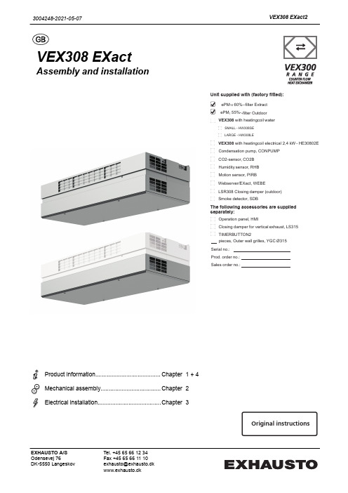
VEX308 EXactAssembly and installationProduct information........................................Chapter1 + 4Mechanical assembly.....................................Chapter2Electrical installation.......................................Chapter 3Unit supplied with (factory fitted):ePM 10 60%--filter Extract ePM 1 55%--filter Outdoor VEX308 with heatingcoil waterSMALL - HW308SELARGE - HW308LEVEX308 with heatingcoil electrical 2,4 kW - HE30802E Condensation pump, CONPUMP CO2-sensor, CO2B Humidity sensor, RHB Motion sensor, PIRB Webserver/EXact, WEBE LSR308 Closing damper (outdoor) Smoke detector, SDBThe following accessories are supplied separately:Operation panel, HMIClosing damper for vertical exhaust, LS315 TIMERBUTTON2pieces, Outer wall grilles, YGC Ø315Serial no.: Prod. order no.: Sales order no.:Original instructions3004248-2021-05-07VEX308 EXact2EXHAUSTO A/S Odensevej 76DK-5550 LangeskovTel. +45 65 66 12 34Fax +45 65 66 11 10********************www.exhausto.dk1.Product information1.1.Location in room....................................................................................................51.1.1.Optimum location ............................................................................................51.1.2.Space requirements ........................................................................................51.2.Application.............................................................................................................61.3.Designations used in these instructions.............................................................61.3.1.Simplified diagram............................................................................................61.4.Description.............................................................................................................81.4.1. Construction of the VEX unit...........................................................................81.4.2.VEX unit, parts and materials...........................................................................91.5.Principal dimensions. (10)Ceiling mounting - visible ..............................................................................101.5.1.Partly integrated ceiling mounting (11)2.Mounting2.1.Unpacking.............................................................................................................122.2.Wall mounting (accessories for some models).................................................122.2.1.Requirements for wall ...................................................................................122.2.2.Instructions and warnings .. (12)Wall mounting step by step (12)2.3.Ceiling mounting..................................................................................................132.3.1.Ceiling requirements......................................................................................132.3.2.Instructions and warnings .............................................................................132.3.3.Ceiling mounting step by step .......................................................................142.4.Partly integrated mounting.................................................................................142.5.Connection of condensation outlet....................................................................152.5.1.Condensation outlet guide channels (if condensation pump is mounted)......152.6.Connection of water heating coil (option).........................................................152.6.1.Connecting the water. (15)3.Electrical installation3.1.Supply voltage and fuses....................................................................................163.1.1.Position of power socket.. (16)Maximum power consumption ......................................................................163.1.2.Permanent installation (16)4.Technical data4.1.Weight, corrosion class, temperature ranges, etc............................................174.2.Electrical data for unit without heating coil......................................................174.3.Data for unit with heating coil.............................................................................174.3.1.Electric heating coil........................................................................................174.3.2.Water heating coils.........................................................................................184.3.3.MVM motor valve ..........................................................................................194.4.Condensate pact filters.....................................................................................................194.6.Capacity diagram and diagram for specific power consumption...................204.6.1.Capacity diagram...........................................................................................204.6.2.Capacity diagram - mounting on "duct system" ............................................214.6.3.Specific power consumption, SFP . (22)2/24Symbols, terms and warningsProhibition symbolFailure to observe instructions marked with a prohibition symbol may result in serious or fatal injury.Danger symbolFailure to observe instructions marked with a danger symbol may result in personal injury and/or damage to the unit.ScopeThis instruction manual is for use with EXHAUSTO VEX-type air handling units.Please refer to the product instructions regarding accessories and extra equip-ment.The instructions must be fully observed to ensure personal safety and to protect the equipment and ensure its correct operation. EXHAUSTO A/S accepts no liabil-ity for accidents caused by equipment not used in accordance with the manual’s instructions and recommendations.Prohibited usesThe VEX unit is not to be used to transport solid particles or in areas where there is a risk of explosive gases.Warnings:StartupThe unit must not be started up until it is fully mounted with door and duct connections.Opening the unitDo not open the service door until the supply voltage has been disconnected (remove plug from socket) and the fans have stop-ped.Duct termination atwallMount a permanent protective mesh to the exhaust and outdoor air connection, using a mesh size of max. 20 mm. For example,use the EXHAUSTO outer wall grilles.Information plateThe VEX unit information plate shows:●VEX model (1)●Production order no. (2)12NB:Always have the production number ready when contacting EXHAUSTO A/S.3/24NB:Find the newest version of the publication by searching for the order number on the EXHAUSTO website under DownloadsSupply air/extract air This instruction manual uses the following terminology:●Supply air (air blown in)●Extract air (air removed)●Outdoor air●Exhaust airFront page - Acces-sories The front page of the instruction manual contains a checklist, detailing the acces-sories delivered with the VEX unit.4/241. Product information1.1 Location in room1.1.1 Optimum locationAs far as possible the unit should be located in the middle of the wall.Avoid placing the VEX308 on the long side of narrow rooms.1.1.2 Space requirements0The sketch shows how much space is required under the unit for opening the door and servicing. The dimensions at the sides of the unit indicate the minimum clear-ance for optimum servicing conditions.R D 13146-015/241.2 ApplicationComfort ventilation EXHAUSTO's VEX308 unit is used for comfort ventilation in frost-free single-room locations. The VEX unit is designed for wall or ceiling mounting and must be usedas such.Operating temperature range for unit see section "Technical data".1.3 Designations used in these instructions1.3.1 Simplified diagramWith integral waterheating coil, HCW(top view)6/24With integral elec-tric heating coil,HCE (top view)7/241.4 Description1.4.1 Construction of the VEX unitThe drawing below shows an overview of the VEX unit construction. Details of HCW and HCE are viewed from below:EC H WC HR D 13198-038/241.4.2 VEX unit, parts and materialsCabinet The exterior of the cabinet is made of Aluzinc® and the cabinet is insulated with20 mm sound insulation material.Fans The unit contains two centrifugal fans with EC motors for extract air and supply air.Counter flow heat exchanger The unit's counterflow heat exchangers are made of aluminium and are highly effi-cient. The counterflow heat exchangers can be taken out and cleaned.Filters The unit includes integral compact filters on both extract air and supply air sides, the ePM10 60% and ePM1 55% filter respectively.Condensation out-let The condensation tray is located under the counterflow heat exchangers. There will only be a condensation outlet from the condensation tray if a condensation pump has been purchased. See also section on connection of condensation out-let.Bypass damper The unit has a variably adjustable bypass damper for temperature regulation and de-icing of counterflow heat exchangers during operation. See operating and serv-ice instructions for further description of de-icing.9/241.5 Principal dimensionsCeiling mounting - visibleR D 13126-02AA10/241.5.1 Partly integrated ceiling mountingR D 13446-03A-A3004248-2021-05-07Product information2. Mounting2.1 UnpackingStandard delivery●VEX308 unit●Housing panels packed separately●Wall brackets premounted on VEX (accessories on some models)●Ceiling brackets, supplied separatelySee information about included accessories on front page of these instructions. Any included ac-cessories2.2 Wall mounting (accessories for some models)2.2.1 Requirements for wallFor wall mounting, it is a requirement that the wall is:●flat●vibration-resistant●plumb (max. 4 mm per metre)●in a material suitable for safe mounting of the unit2.2.2 Instructions and warningsDimensioning Wall mountings must be dimensioned from the unit's weight.Mounting must be carried out in accordance with the ProjectManager's instructions.For wall mounting the two front ceiling brackets should also beused.Suspension The unit must be suspended with the door facing the floor. Theunit must not be mounted in any other way.The housing panels must be fixed with the accompanyingscrews.Wall mounting step by stepSee the attached installation guide (3004368).NB The dimensions of the wall template will match when held right up to the ceiling.2.3 Ceiling mounting2.3.1 Ceiling requirements0When fitting the unit to a ceiling, the ceiling must be:●flat●vibration-resistant ●horizontal●designed to bear the weight of the unit2.3.2 Instructions and warnings DimensioningCeiling mountings must be dimensioned from the unit's weight.Mounting must be carried out in accordance with the Project Manager's instructions.SuspensionThe unit must be suspended with the door facing the floor. The unit must not be mounted in any other way.The housing panels must be fixed with the accompanying screws.2.3.3 Ceiling mounting step by stepSee the attached installation guide (3004368).*) To be carried out in the event that the VEX has not been ordered with exhaust/outdoor air connection via the ceiling.2.4 Partly integrated mountingInstallationInstallation of the partly integrated VEX is carried out as described in sections 2.2.and 2.3.Access to control systemWhen carrying out installation, ensure there is access to the control system. EX-HAUSTO recommends that the part of the ceiling next to the control system can be removed.NBThe partly-integrated VEX extracts a small amount of air above the suspended ceiling, which can cause the filter to soil more quickly than usual. EXHAUSTO rec-ommends leaving a 10 mm gap between the cabinet and the suspended ceiling.2.5 Connection of condensation outlet2.5.1 Condensation outlet guide channels (if condensation pump is mounted)Wall-mounted VEX On wall-mounted units the condensation outlet is positioned with the outlet pass-ing through the exhaust duct.Ceiling-mounted VEXOn ceiling-mounted units the condensation outlet is led through the internal guidechannels (rubber sleeves) out of the unit to the drain.The penetrations in the unit must be executed so as to retain air tightness.Condensate pump (optional/accesso-ry)For technical data, see final section.2.6 Connection of water heating coil (option)2.6.1 Connecting the water Valves for water connectionIt is recommended that shut-off valves are mounted on both water connections toenable the flow to be interrupted for servicing.The dimensioning of valves, pipes, etc. and the connection of the water heating coil must always be carried out by authorised fit-ters in accordance with applicable regulations and legislation.Position of bleeder valve on VEX See keyed drawing for position of internal bleeder valve.Automatic bleeder valveIf the water connection is executed with vertical riser, so the heating coil in the VEX308 is the highest point in the pipe system, it is recommended that an auto-matic bleeder valve is fitted at the highest point on the supply and return pipes.3. Electrical installation3.1 Supply voltage and fuses3.1.1 Position of power socketThe supply cable is fitted with a 230V plug and can thus be connected to a powersocket.Fit the power socket for the supply voltage close to the VEX unit and preferably within the easy reach of users of the room.Maximum power consumptionFuses The installation must be protected with a max. 16A fuse.3.1.2 Permanent installationIf the plug is cut off and the cable mounted in a permanent installa-tion, an isolation switch must be established at the time of installa-tion.Permanent installation must be carried out by an authorised electri-cian.3004248-2021-05-07Electrical installation4. Technical data4.1 Weight, corrosion class, temperature ranges, etc.WeightDoor25.5 kgCounter flow heat exchanger 2 x 11 kgMotor section 2 x 6.0 kgTotal weight184.5 kg incl. HW308SEPartly integrated203.0 kg incl. HW308SE Corrosion class,cabinet Corrosion class Corrosion class C4 in accordance with EN ISO 12944-2Temperature rangesOutdoor air temperature-40 - +40°CAmbient temperature (operating)-30 - +40ºCAmbient temperature when not in operation (storage, transport)-40 - +60ºCThe temperature ranges given are dependent on the type of installation, humidity,airflow, the balance between airflows, ducts and insulation and room temperature.If using pre-heating coils, the ambient temperature can be reduced.At temperatures below -25˚C, use of a thermostatically controlled heater in auto-mated control box is recommended.4.2 Electrical data for unit without heating coilVoltage 1 x 230 V+N+PEMaximum output575 WMaximum power consumption 2.5 A4.3 Data for unit with heating coil4.3.1 Electric heating coilElectrical data forVEX with electric heating coilHE30802E Voltage 1 x 230 V+N+PE Maximum output, HE30802E2975 W Maximum power consumption12.9 AData, thermal cut-out Thermal fuse, TSA7070 ℃Thermal fuse, TSA9090 ℃Contact type NC (Normally closed)Maximum load 1.6 A @ 24 V DC NB Motors and heating coils may not be interrupted/switched off via OH70 and OH904.3.2 Water heating coilsElectrical data forVEX with water heating coil HCW Voltage 1 x 230 V+N+PE Maximum output575 W Maximum power consumption 2.5 AWater heating coildataOutput, K VS mv.Conditional upon: Supply temperature of water t F= 50°C and ΔT = 20K.4.3.3 MVM motor valve4.4 Condensate pumpCondensate pumpMaximum power consumption16WMaximum lifting height 5.0mHose dimension dia. 4/8 mm 4.5 Compact filtersFilter data, VEX308,filter data accordingto ISO168904.6 Capacity diagram and diagram for specific power consumption4.6.1 Capacity diagram Read control volt-ageWhen an EXact control panel (HMI) is connected to the VEX unit, the control volt-age can be read from menu 2.3 and thereby give a reasonable reading of airflow on the diagram. Conditional upon: 750 m 3/h at 35 Pa.1) Visible unit max. 750 m 3/h2) Partly integrated unit max. 650 m 3/h4.6.2 Capacity diagram - mounting on "duct system"1) Visible unit max. 750 m3/h2) Partly integrated unit max. 650 m3/h21/244.6.3 Specific power consumption, SFP1) Visible unit max. 750 m3/h2) Partly integrated unit max. 650 m3/h22/243004248-2021-05-0723/24。
icharger 308duo 充电器中文说明书
308DUO 使用说明书( V1.5.0 )目录使用须知 ................................................................................................................................................................. - 4 - ● 安全须知........................................................................................................................................................... - 4 - ● 版权声明........................................................................................................................................................... - 4 - ● 308DUO性能特点......................................................................................................................................... - 5 - ● 外观参数........................................................................................................................................................... - 5 - ● 电性能参数....................................................................................................................................................... - 5 - 设备简介 ................................................................................................................................................................. - 6 - ● 308DUO部件、接口名称............................................................................................................................. - 6 - ● 308DUO按键功能、界面图标 ..................................................................................................................... - 6 - ● 308DUO标准配件......................................................................................................................................... - 8 - ● 308DUO选购配件......................................................................................................................................... - 8 - 充电器的连线 ......................................................................................................................................................... - 9 - ● 电源输入地线不能与输出地线连通............................................................................................................... - 9 - ● 接线顺序........................................................................................................................................................... - 9 - ● 双通道的连线方式........................................................................................................................................... - 9 - ◆ 通道异步模式连线方式 ............................................................................................................................... - 9 - ◆ 通道同步模式连线方式 ............................................................................................................................... - 9 - 充电器充放电程序设置及使用 ........................................................................................................................... - 10 - ● 电源设置......................................................................................................................................................... - 10 - ● 程序添加与管理............................................................................................................................................. - 11 - ● 运行充电器程序............................................................................................................................................. - 11 - ● 程序运行状态................................................................................................................................................. - 12 - ● 错误提示......................................................................................................................................................... - 13 - ● 程序编辑......................................................................................................................................................... - 13 - ◆ LiPo/LiIo/LiFe电池的充放电设置.......................................................................................................... - 14 -❑ LiPo/LiIo/LiFe电池充电设置 ............................................................................................................ - 14 - LiPo/LiIo/LiFe电池的非平衡充电 .............................................................................................. - 15 - LiPo/LiIo/LiFe电池的平衡充电 .................................................................................................. - 15 - LiPo/LiIo/LiFe电池充电Advanced设置 .................................................................................... - 16 - LiPo/LiIo/LiFe电池充电SAFETY设置 ..................................................................................... - 16 - ❑ LiPo/LiIo/LiFe电池储存模式设置 .................................................................................................... - 17 - ❑ LiPo/LiIo/LiFe电池放电设置 ............................................................................................................ - 17 - To channel模式设置 ..................................................................................................................... - 17 - LiPo/LiIo/LiFe电池放电Advanced设置 .................................................................................... - 18 - LiPo/LiIo/LiFe电池放电Safety设置 .......................................................................................... - 18 - ❑ LiPo/LiIo/LiFe电池循环充放电设置 ................................................................................................ - 18 - ❑ LiPo/LiIo/LiFe电池执行平衡功能 .................................................................................................... - 18 - ◆ NiMH/NiCd电池的充放电设置 .............................................................................................................. - 19 -❑ NiMH/NiCd电池充电设置................................................................................................................. - 19 - NiMH/NiCd电池充电Advanced设置 ........................................................................................ - 19 - NiMH/NiCd电池充电Safety设置 .............................................................................................. - 19 -❑ NiMH/NiCd电池放电设置................................................................................................................. - 20 - NiMH/NiCd电池放电Safety设置 .............................................................................................. - 20 - ❑ NiMH/NiCd电池循环充放电设置..................................................................................................... - 20 - ◆ Pb电池的充放电设置 .............................................................................................................................. - 20 -❑ Pb电池充电设置 ................................................................................................................................ - 20 - Pb电池充电Advanced设置 ........................................................................................................ - 21 - Pb电池充电Safety设置 .............................................................................................................. - 21 - ❑ Pb电池电池放电设置......................................................................................................................... - 21 - ❑ Pb电池循环充放电设置..................................................................................................................... - 21 - ◆ NiZn电池的充放电设置.......................................................................................................................... - 21 -❑ NiZn电池充电设置 ............................................................................................................................ - 21 - NiZn电池的非平衡充电 .............................................................................................................. - 22 - NiZn电池的平衡充电 .................................................................................................................. - 22 - NiZn电池充电Advanced设置 .................................................................................................... - 22 - NiZn充电SAFETY设置 ............................................................................................................. - 22 - ❑ NiZn电池放电设置 ............................................................................................................................ - 22 - To channel模式设置 ..................................................................................................................... - 22 - NiZn电池放电Advanced设置 .................................................................................................... - 22 - NiZn电池放电Safety设置 .......................................................................................................... - 22 - ❑ NiZn电池循环充放电设置 ................................................................................................................ - 22 - 308DUO参数设置 ............................................................................................................................................... - 23 - ● 308DUO参数设置....................................................................................................................................... - 23 - ◆ Charger Setup ............................................................................................................................................ - 23 -❑ 温度&风扇设置..................................................................................................................................... - 23 - ❑ 提示音设置............................................................................................................................................ - 24 - ❑ LCD设置............................................................................................................................................. - 24 - ❑ 输出功率设置........................................................................................................................................ - 24 - ❑ 电源设置................................................................................................................................................ - 25 - ❑ 保存&加载配置文件设置..................................................................................................................... - 26 - ❑ 通信方式................................................................................................................................................ - 26 - ❑ 语言设置................................................................................................................................................ - 26 - ❑ 设备校准................................................................................................................................................ - 27 - ◆ Extra Function ........................................................................................................................................... - 28 -❑ 日志文件管理........................................................................................................................................ - 28 - ❑ 伺服器测试............................................................................................................................................ - 28 - ❑ 脉冲测试................................................................................................................................................ - 29 - ● USB & SD卡的使用.................................................................................................................................... - 30 - ● 保修及服务..................................................................................................................................................... - 30 - 308DUO固件升级 ............................................................................................................................................... - 31 - ● 通过USB接口更新固件 ............................................................................................................................... - 31 - ● 通过SD卡更新固件...................................................................................................................................... - 32 - 308DUO接入LogView ....................................................................................................................................... - 33 - ● LogView的使用步骤................................................................................................................................... - 33 - 重要提示 ............................................................................................................................................................... - 35 - ● 反射充电模式的充电原理............................................................................................................................. - 35 -● 电源回充模式................................................................................................................................................. - 35 - ● 通道再生模式................................................................................................................................................. - 35 - ◆ Resistance or bulbs .................................................................................................................................... - 35 - ◆ Charging battery ........................................................................................................................................ - 36 - ● 锂电池外部扩展放电模式............................................................................................................................. - 36 - 附录....................................................................................................................................................................... - 37 - ● 通道运行状态指示......................................................................................................................................... - 37 - ● 通道控制状态指示......................................................................................................................................... - 37 - ● 错误指示......................................................................................................................................................... - 37 -使用须知●安全须知使用充电器前,请认真阅读本章节内容;以便于您更放心、更安全的使用充电器。
汉龙EHS30适配器用户手册说明书
Htek EHS30 Adapter User ManualVersion 2.0.4.4.24Feb. 2018Notices InformationCopyrightCopyright © 2005 - 2018 Nanjing Hanlong Technology CO., LTD. All rights reserved.Nanjing Hanlong Technology Co., LTD. owns all the rights to modify and copy this document at any time. And all the illustrations and text in this document are copyright protected. Therefore, no parts of this document may be used or reproduced, transmitted by the third parties for any purposes without the express written permission of Nanjing Hanlong Technology CO., LTD.When this document is made available on , Nanjing Hanlong Technology Co., LTD. gives its right to download and print copies of this content only for private use as a user manual. No parts shall have the right to alter, modify or use as commercial means without prior written permission from Nanjing Hanlong Technology Co., LTD.Safety Instructions●To use the EHS30, please follow the instructions in this user manual.●This EHS30 is only for indoor use. And also avoid in high humidity, water and someother liquids.●Do not use the EHS30 during thunderstorms.●CE●FCCWEEE WarningTo avoid the potential effects on the environment and human health as aresult of the presence of hazardous substances in electrical and electronicequipment, end users of electrical and electronic equipment shouldunderstand the meaning of the crossed-out wheeled bin symbol. Do notdispose of WEEE as unsorted municipal waste and have to collect such WEEE separately.CleaningTo clean the device, use an anti-static cloth. Please avoid cleaning liquids as they might damage the surface or internal electronics of the EHS30.FCC Statement1. This device complies with Part 15 of the FCC Rules. Operation is subject to the following two conditions:(1) This device may not cause harmful interference.(2) This device must accept any interference received, including interference that may cause undesired operation.2. Changes or modifications not expressly approved by the party responsible for compliance could void the user's authority to operate the equipment.NOTE: This equipment has been tested and found to comply with the limits for a Class B digital device, pursuant to Part 15 of the FCC Rules. These limits are designed to provide reasonable protection against harmful interference in a residential installation.This equipment generates uses and can radiate radio frequency energy and, if not installed and used in accordance with the instructions, may cause harmful interference to radio communications. However, there is no guarantee that interference will not occur in a particular installation. If this equipment does cause harmful interference to radio or television reception, which can be determined by turning the equipment off and on, the user is encouraged to try to correct the interference by one or more of the following measures:Reorient or relocate the receiving antenna.Increase the separation between the equipment and receiver.Connect the equipment into an outlet on a circuit different from that to which the receiver is connected.Consult the dealer or an experienced radio/TV technician for help.Table of Content Table of ContentNotices Information (2)Copyright (2)Safety Instructions (2)WEEE Warning (2)Cleaning (2)FCC Statement (3)Table of Content (4)Introduction (5)Description (5)Compatibility (5)Getting Started (6)EHS-30 Package Contents (6)EHS-30 Ports and LEDs Description (6)Installation for Plantronics Headsets (7)Installation for Jabra Headsets (7)Installation for SENNHEISER Headsets (8)IP Phone Configuration (for all Wireless Headsets) (10)Headset Usage (for all Wireless Headsets) (11)Introduction IntroductionDescriptionThe Htek™ EHS30 Wireless Headset Adapter is perfect for connecting Htek phones to supported wireless headsets. It is simple to use and install, and allows the user to control off-hook, talk, and on-hook modes of Htek (Hanlongtek) IP phones from the headset. The EHS Adapter connects between the Htek IP phone and the Wireless Headset base unit.CompatibilityHtek IP Phones *: UC926, UC926E, UC924, UC924E, UC923, UC903, UC862, UC842, UC860, UC840, UC806, UC806T, UC806G, UC804, UC804T and UC804G.Plantronics® Wireless Headsets: Plantronics CS510, CS520, CS540. (Headset bases C052 and C054)Jabra® Headsets: 9400BS (9460), WHB005BS(U) (925), BT2046.SENNHEISER® Wired headset: SC230,SC260,SC660SENNHEISER® Wireless Headsets: DW Pro2,SD Pro2,D10*Firmware Note: Plantronics Headsets require Htek firmware 1.0.3.88 (2015_08_21) or later, and Jabra Headsets require Htek firmware 1.0.3.94 or later.Getting StartedEHS-30 Package ContentsEHS-30 Ports and LEDs Description(1) RJ-12 Port for IP Phone EXT/EHS or Expansion Module(2) Operation LED(3) 3.5mm DC Power Jack (for Plantronics Headsets)(4) RJ-45 Jack (for Jabra Headsets)Installation for Plantronics HeadsetsThe following figure shows the connections between the EHS-30 Adapter, the bottom of the Htek IP Phone, and the Plantronics wireless headset base unit.Steps:1.Connect the Wireless Headset to the RJ-9 Headset port on the IP Phone, using the cord provided by Plantronics.2. Connect the included RJ-12 cord between the EHS-30 Adapter RJ12 Port (Port 1) and the EXT/EHS port of the Htek IP Phone (or to the Expansion Module EXT port, if the expansion module is connected).3. Connect the 3.5mm DC Power Port (Port 3) of the EHS-30 Adapter to the Plantronics Wireless headset using the included 3.5mm DC power cord.Note: For Plantronics Headsets, the RJ45 jack of the EHS-30 Adapter is not used. Installation for Jabra HeadsetsThe following figure shows the connections between the EHS-30 Adapter, the bottom of the Htek IP Phone, and the Jabra wireless headset base unit.Steps:1.Connect Aux Port of the Jabra Wireless Headset to the RJ45 port (Port 4) of the EHS-30 Adapter. (The RJ-45 cord may be supplied by Jabra or obtained separately).2. Connect the included RJ-12 cord between the EHS-30 Adapter RJ12 Port (Port 1) and the EXT/EHS port of the Htek IP Phone (or to the Expansion Module EXT port, if the expansion module is connected).3. Connect the RJ-9 cord from the Jabra Wireless Headset to the Headset jack of the Htek IP phone.Note: For Jabra Headsets, the 3.5mm DC Power jack and cord are not used. Installation for SENNHEISER HeadsetsThe following figure shows the connections between the EHS-30 Adapter, the bottom of the Htek IP Phone, and the SENNHEISER wireless headset base unit.Steps:1. Connect EHS Port of the SENNHEISER Wireless Headset to the RJ45 port (Port 4) of the EHS-30 Adapter. (The RJ-45 cord may be supplied by SENNHEISER or obtainedseparately).2. Connect the included RJ-12 cord between the EHS-30 Adapter RJ12 Port (Port 1) and the EXT/EHS port of the Htek IP Phone (or to the Expansion Module EXT port, if the expansion module is connected).3. Connect Telephone Port of the SENNHEISER Wireless Headset to the Headset jack of the Htek IP phone.Note:For SENNHEISER Headsets, the 3.5mm DC Power jack and RJ45 jack are not used.IP Phone Configuration (for all Wireless Headsets) IP Phone Configuration (for all Wireless Headsets)For Wireless Headset operation, set the following parameters using the IP Phone Web GUI interface:1. Log in to the Web Configuration GUI for the IP Phone (as described in the User Manual).2. Go to Setting -> Preference3. Set “HeadSet Priority” to “Enable”4. Set “Ringer Device For HeadSet” to “Use HeadSet”Refer to the picture below for the correct settings:Headset Usage (for all Wireless Headsets)11Headset Usage (for all WirelessHeadsets)To use the connected Wireless headset (instead of the IP Phone handset), press the Headset key on the keyboard of the phone. The key will light to indicate that you are in Headset mode. Now you can use the wireless headset. To return to normal operation using the handset, press the Headset key again. The key backlight will turn off to indicate that the headset is not active.Please Note :(1) EHS version 0.2 just support Protocol IQ of Jabra wireless headset , But ,EHS version 0.3 support Protocol IQ and DSHG of Jabra wireless headset(2) EHS 30 support two protocol ( IQ , DSHG ) of Jabra Wireless headset . In order to make our phone can recognize which kind of protocol the Jabra Wireless headset use . Please press the off-hook button on headset in the followed two situation:1 : when you use the Jabra wireless headset (protocol DSHG) first time . After connect the devices and complete the webpage setting , please press the off-hook button on headset.2 : When the Jabra wireless headset(Protocol DSHG) in use , after the phone restart or reboot every time , please press the off-hook button on headset.。
dopodD802用户手册

3.1.3 “今日”屏幕3.1.4 状态图标3.1.5 程序3.1.6 导航条与指令条3.1.7 弹出菜单3.1.8 通知3.2 输入信息3.2.1 使用输入面板3.3 在屏幕上书写3.4 在屏幕上画图3.4.1 创建一个图形3.4.2 选择图形3.5 录音3.5.1 单独录音3.5.2 在文档中嵌入录音3.6 搜索3.7 使用常用短语第四章使用您的电话4.1 电话功能简介4.1.1 关于拨号界面4.1.2 输入PIN号4.1.3 检查网络连接4.1.4 打开/关闭飞行模式4.1.5 调整通话/铃声音量4.2 拨打电话4.2.1 从拨号界面拨打电话4.2.2 从联系人列表拨打电话 2425262828292930323333343434363637383838393939404141414.2.3 从快速拨号中拨打电话4.2.4 从通话记录中拨打电话4.2.5 拨打紧急电话4.2.6 拨打国际长途4.3 接听或拒接来电4.4 打开扬声器功能4.5 电话随笔4.5.1 创建电话随笔4.5.2 查看电话随笔4.6 语音信箱4.7 导入/导出联系人4.7.1 从通话记录中创建联系人4.8 使用PIN码保护您的电话第五章同步信息5.1 同步数据5.1.1 同步电子邮件的收件箱5.1.2 同步日历5.1.3 同步联系人5.1.4 同步任务5.1.5 同步步骤5.2 传输文件第六章定制多普达D8026.1 调整设置参数6.2 标签6.3 主人信息6.4 今日6.5 声音和提醒4246474848494949505051515152535353545454585858596161626364656868696970717475777777787979798081828282838383846.6 密码 6.7 按键 6.8 电话 6.9 菜单 6.10 输入 6.11 关于 6.12 内存 6.13 删除程序 6.14 时钟和闹钟 6.15 电源 6.16 背景灯第七章 个人信息管理功能 7.1 日历7.1.1 显示约会列表 7.1.2 创建一次约会 7.1.3 使用摘要 7.2 联系人7.2.1 显示联系人列表 7.2.2 创建联系人 7.2.3 查找联系人 7.3 任务7.3.1 显示任务列表 7.3.2 创建一个任务 7.4 便笺7.4.1 显示便笺列表 7.4.2 创建一个便笺 第八章 网络应用848485868891929296979899991091051081081101101101121131131161161161178.1 连接8.2 Internet 设置 8.3 WAP 设置8.4 Internet Explorer Mobile 8.5 Pocket MSN 8.6 蓝牙8.6.1 蓝牙模式 8.6.2 绑定 8.6.3 蓝牙FTP8.6.4 通过蓝牙无线发送数据 8.6.5 通过蓝牙无线接收数据 第九章 信息功能 9.1 信息概述 9.2 短信 9.3 彩信9.3.1 创建与编辑彩信 9.3.2 发送和接收彩信 9.3.3 转发彩信第十章 商务程序 10.1 Word Mobile 10.2 Excel Mobile10.3 PowerPoint Mobile 10.4 Adobe Reader LE 10.5 图片和视频 10.5.1 传送图片10.5.2 查看图片和视频 10.5.3图片排序1.点击如果您希望输入的汉字没有声母,请点击软键盘上的2.摄像:点击3.浏览图像:在拍摄界面用触笔选择 ,即可进入图像浏览。
电动车充电器使用方法说明书

电动车充电器使用方法说明书使用方法说明书 - 电动车充电器一、产品概要电动车充电器是一种电动车配件,用于给电动车电池充电。
本说明书将详细介绍如何正确地使用和操作电动车充电器。
二、安全提示在使用电动车充电器之前,请务必阅读以下安全提示,并遵循相关操作规程以确保您的安全和充电器的正常使用。
1. 请在安全环境下使用充电器。
确保充电区域通风良好,远离易燃物品和水源。
2. 请勿将充电器接触湿手、湿地或放置在潮湿环境中。
3. 请勿在充电器损坏或线缆受损时使用,以免发生电击或其他安全事故。
4. 请勿自行拆解或修理充电器。
如有故障,请联系专业人士进行检修。
5. 当充电器闲置时,请拔掉电源插头,以避免不必要的事故发生。
三、充电器使用方法在开始正式使用电动车充电器之前,请确保您已具备以下条件并准备好相关设备:1. 检查电动车电池和车辆充电接口是否符合本充电器的兼容性要求。
2. 确保充电器已经正确连接到电源,并稳固地插入相应的插座上。
以下是使用电动车充电器的详细步骤:步骤一:检查连接将充电器的连接线插入电动车的充电接口上,确保插头与接口完全贴合且稳固。
步骤二:连接电源将充电器的电源插头插入交流电源插座中,确保接地线已正确连接。
步骤三:设置充电模式根据电动车电池的类型和具体需求,选择充电模式。
充电器通常提供不同的充电模式以适配各种电池。
步骤四:开始充电在检查完所有连接后,按下充电器上的启动按钮,充电器将开始工作并为电动车电池充电。
四、使用注意事项为了延长充电器的使用寿命并确保充电过程的高效性,以下是您在使用过程中应该注意的事项:1. 在充电过程中,请勿拔掉充电器或断开电源,以确保充电过程的连续性。
2. 充电器在工作过程中会产生一定的余热,请确保不要将充电器放置在易燃物体旁边,也不要覆盖充电器散热口。
3. 建议在安全环境下进行充电,以避免在充电过程中发生意外。
4. 在充电过程中,如发现任何异常情况(如烟雾或其他不正常噪音),请立即中断充电并联系售后服务。
苹果充电器中文说明 - -B2B

USB多功能移动充电器使用说明书USB多功能移动充电器是专为手机、MP3、MP4、DV数码相机、掌上电脑、iPOD数码产品等设计的电池充电专用设备。
为了保护您的利益和延长充电器的使用寿命,在使用多功能充电器前请阅读以下说明:一、主要功能1.集AC输入、USB输入输出、储能、USB升压、DC输出供电充电于一体。
2.红黄绿蓝LED灯,充放电状态显示,工作状态一目了然。
3.方便的伸缩线、USB输入输出,可以边充边用,是真正的移动电源。
4.完善的保护,具备电流、电压、充电、放电、负载、短路、温度等多重保护功能。
二、使用说明1.用AC 100~240V 电源向内置电池充电:插入AC电源,正在充电时,红色灯亮,直至绿色、蓝色灯亮时,充满结束。
2.用USB接口对内置电池充电:在USB口插入外部USB电源,开关-IN位置,正在充电时,红色灯亮,直至绿色灯亮时,充满结束。
3.直接用AC 100~240V电源向用电设备充电:插入AC电源,在DC输出口或USB口(开关-OUT)插上用电设备,蓝色灯亮时,用电设备充电结束,AC电源会继续对内部电池充电,绿色灯亮时,内置电池充满结束。
4.用USB电源升压后向用电设备充电:在USB口插入外部USB电源(开关-IN),在DC输出口,插上用电设备,蓝色灯亮时,用电设备充电结束,USB电源会继续对内部电池充电,绿色灯亮时,内置电池充满结束。
5.二路输出移动充电:将伸缩线插头插入DC插孔,或开关-OUT位置DC口和USB口可以同时输出,蓝色和黄色灯亮(微闪属正常),接上用电设备或在USB口插上USB用电设备,蓝色灯熄灭(或闪烁-视用电设备不同闪烁频率也不同),直至蓝色灯常亮时,充电结束。
三、注意事项1.一般内部充电时间6-10小时,外部充电时间1-4小时。
2.外部设备充电结束后,请及时拔下输出插头和开关-IN位置。
3.请勿于高温或潮湿环境中使用或存放。
四、技术参数USB Multi-function Portable Charger User GuideThis product is a multi-function portable charger designed for Mobile 、MP3、MP4、DV、Portable PC 、a series of iPod digital products. For pretect yourself benefit and extend the charger life, Please read carefull the guide before use.一、Features1.Built in AC input, USB input and output, storage, USB power Step up,output DC power supply.2.Red-yellow-green-blue LED Lights, charge and discharge status, working status display.B telescopic line input and output , it is a truly portable power supply.4.Seven categories protection with over current, over voltage, over charge and over discharge, over load, short-circuit,high temperature.二,Operation1.AC100~240V power for charging the internal battery :as the Charge connected to AC power supply , the internal battery of charge is charging, the red lights. So green , blue LED lights, with the end..B interface for charging the internal battery : USB interface connectedto USB external power port(Switch -IN), is charging that the red LED lights, until the green LED lights, with the end.3.AC100~240V power for charging external device :the charge connectedto AC power,DC JACK or the USB port (Switch -OUT) connected to electrical equipment, when the blue LED lights, Charging end. AC100~240V power will charge for the internal battery, and the green LED lights, batteries charging end.4.Step up USB power voltage for charging the electronic equipment :USB interface connected to USB external power port(Switch -IN),digital product DC port connected to DC jack , when the blue LED lights, electrical equipment charging end.The external USB power will continue to chargefor internal batteries, when the green LED lights, batteries charging end.5、Two port output charging:USB telescopic line plugs connected to DC JACK (or Switch -OUT ), Charger USB port and DC port can export voltage,The blue and yellow LED lights (scintillation:normal). Digital product connected to the USB port or DC JACK ,the Blue LED lights out (or scintillation - As digital devices is different, scintillation frequency is different)。
Plug and Play温度控制器ITC-308用户手册说明书

Plug and Play Temperature ControllerITC-308User ManualVersion 2.2sInkbird Tech. Co., Ltd.CopyrightCopyright©2016 Inkbird Tech. Co., Ltd. All rights reserved. No part of this document may be reproduced without prior written permission.DisclaimerInkbird has made every effort to ensure that the information contained in this document is accurate and complete; however, the contents of this document are subject to revision without notice. Please contact Inkbird to ensure you have the latest version of this document.Contents1. Overview (3)What is ITC-308? (3)Main features (3)2. Specification (4)3. Keys Instruction (5)4. Key Operation Instruction (6)4.1 Enquiry Set Point (6)4.2 How to Set Parameters (6)4.3 Setup Flow Chart (7)5. Menu Instruction (7)5.1 Temperature Control Range Setting (TS, HD, CD) (8)5.2 Alarm High/Low Limit Setting (AH, AL) (8)5.3 Compressor Delay (PT) (9)5.4 Temperature Calibration (CA) (9)5.5 Display in Fahrenheit or Centigrade unit (CF) (9)6. Error Description (10)Sensor Fault Alarm (10)Over-temperature Alarm (10)7. Technical Assistance and Warranty (11)7.1 Technical Assistance (11)7.2 Warranty (11)1. OverviewWhat is ITC-308?ITC-308 is an easy-to-use, safe and reliable dual relay output temperature controller. It can be used as over-temperature protection and automatic temperature control system for various electric appliances such as equipment for home-brew, aquarium, pet breeding, incubation, BBQ, seedling heat mats, oven temperature control, terrestrial heat control, constant temperature cycle of heating pump, culture fermentation, accelerating germination, electric radiator, electric oven, etc.This product has plug-n-play design with dual relay, be able to connect with refrigeration and heating equipment easily to realize ideal temperature control. It’s equipped with dual LED display, and offers display options of Centigrade and Fahrenheit, enabling more humanized temperature control. With large output power 1200W(110V) / 2200W(220V), it’s suitable for most applications.ITC-308 is designed with compressor delay protection for refrigeration, high and low temperature alarm, and sensor fault alarm, which makes the temperature controller more safe and reliable. Functions such as temperature calibration, separately set differential for refrigeration and heating, enable more accurate temperature control.Main features•Plug and play design, easy to use;•Dual relay output, be able to connect with refrigeration and heating equipment at the same time;•Support reading with Centigrade or Fahrenheit unit;•Maximum output load: 1200W(110V) / 2200W(220V);•Dual display window, be able to display measured temperature and set temperature at the same time;•Temperature calibration;•Compressor delay protection for refrigeration control;•High and low temperature alarms are available;•Over-temperature and sensor fault alarm;•Heating/cooling differential function could be set separately for refrigeration and heating to protect temperature controller from violent change.2. Specification3. Keys Instruction①PV: Process Value. under running mode, display current temperature; under setting mode, display menu code.②SV: Setting Value. under running mode, display setting temperature; under setting mode, display setting value.③Cooling indicator Lamp:when the light is on, start refrigeration; when the light is flickering, the compressor is under delay protection.④ Heating Indicator Lamp: when the light is on, start heating.⑤SET key: press SET key for 3 seconds to enter menu for function setting. During the setting process, press SET key for 3 seconds to quit and save setting changes.⑥DECRESE key:under running mode, press DECRESE key to inquiry CD value; under setting mode, press DECRESE key to decrease value.⑦INCREASE key: under running mode, press INCREASE key to inquiry HD value; under setting mode, press INCREASE key to increase value.⑧ Heating Device Socket: this socket is for heating output.⑨Cooling Device Socket: the socket is for refrigeration output.4. Key Operation Instruction4.1 Enquiry Set PointWhen the controller is working normally, short press “” key for one time, then the heating differential (HD) will be displayed; short press “” for one time, then the cooling differential (CD) will be displayed. The screen will return to normal display mode after 2 seconds.4.2 How to Set ParametersWhen the controller is working normally, press “SET” key for over 3seconds to enter parameters set up mode. “SET” indicator lamp will on. PV window displays the first menu code “TS”, while SV window displays according setting value. Press “SET” key to go to next menu and display according menu code, press “” key or “”k ey to set current parameter value. After setting done, press “SET” key for 3 seconds at any time to save the parameters change and return to normal temperature display mode. During setting, if there is no operation for 10 seconds, the system will quit setting mode and return to normal temperature display mode without saving the parameters change.4.3 Setup Flow Chart5. Menu InstructionWhen the temperature is displayed in CentigradeWhen the temperature is displayed in Fahrenheit5.1 Temperature Control Range Setting (TS, HD, CD)When the controller is working normally, the LED displays current measured temperature, and automatically identify and switch refrigeration and heating working modes.When the measured temperature PV ≥ TS(temperature set value) + CD (cooling differential value), system enters refrigeration status, the cool indicator lamp will on, and refrigeration relay starts to work; when the cool indicator lamp is flickering, it means the refrigeration equipment is under compressor delay protection status. When the measured temperature PV≤TS (temperature set value), the cool indicator lamp will off, and the refrigeration relay stops working.When the measured temperature PV≤TS (temperature set value)-HD (heating differential value), system enter heating status, the heat indicator lamp will on, and heating relay starts to work; when the measured temperature PV≥ TS(temperature setting), the heat indicator lamp will of, and heating relay stops working.For example, set TS=25°C, CD=2°C , and HD=3°C, then when measured temperature is higher or equal to 27°C(TS+CD), system enters refrigeration status; when temperature decline to 25°C(TS), stop refrigeration; when measured temperature is lower or equal to 22°C(TS-HD), system enters heating status; when the temperature raised to 25°C(TS), stop heating.In case the time interval between two refrigeration is less than PT, please refer to 5.3.5.2 Alarm High/Low Limit Setting (AH, AL)When measured temperature is higher or equal to AH, high temperature alarm will be triggered, buzzer will alarm with tone “bi-bi-Biii” until the temperature is lower than AH or any key is pressed.When measured temperature is lower or equal to AL, low temperature alarm will be triggered, buzzer will alarm with tone “bi-bi-Biii” until the temperature >AL or any key is pressed.5.3 Compressor Delay (PT)Under refrigeration mode, after power on, if the measured temperature is higher than the value of setting temperature(TS) plus cooling differential(CD), the equipment won’t start refrigeration immediately, but waiting for a delay time.When the time interval between two refrigeration operation is larger than preset delay, the equipment will start refrigeration immediately; when the time interval between two refrigeration is less than preset delay, the equipment won’t start refrigeration until preset delay is satisfied.Delay time will be calculated right after the moment refrigeration stops.5.4 Temperature Calibration (CA)When there is deviation between measured temperature and actual temperature, use temperature calibration function to align the measured temperature and actual temperature. The corrected temperature is equal to temperature before calibration plus corrected value(corrected value could be positive value, 0 or negative value).5.5 Display in Fahrenheit or Centigrade unit (CF)Users can select display with Fahrenheit or Centigrade temperature value according to their own habit. Default setting is display with Centigrade temperature value. For displaying with Fahrenheit temperature value, set CF value as F.Attentions: when CF value changed, all the setting value will be recovered to factory settings.6. Error DescriptionSensor Fault Alarm:when temperature sensor is in short circuit or open loop, the controller will initiate sensor fault mode, and cancel all the actions. The buzzer will alarm, LED displays ER. Buzzer alarm could be dismissed by pressing any key. After faults solved, the system will return to normal working mode.Over-temperature Alarm:when measured temperature exceeds the measuring range (less than -50°C /-58° F or higher than 99 °C/210 ° F), the controller will initiate over-temperature alarm mode, and cancel all the actions. The buzzer will alarm, LED displays HL. Buzzer alarm could be dismissed by pressing any key. When temperature returns to measuring range, the system will return to normal working status.ITC-308 User Manual 7. Technical Assistance and Warranty7.1 Technical AssistanceIf you have any problems installing or using this thermostat, please carefully and thoroughly review the instruction manual. If you require assistance, please write us to ***************. We will reply your emails in 24 hours from Monday through Saturday. You can also visit our web site to find the answers of the common technical questions.7.2 WarrantyINKBIRD TECH. C.L. warrants this thermostat for one years from the date of purchase when operated under normal condition by the original purchaser (not transferable), against defects caused by INKBIRD’s workmanship or materials. This warranty is limited to the repair or repl acement, at INKBIRD’s discretion, of all or part of the thermostat. The original receipt is required for warranty purposes.INKBIRD is not responsible for injury property damage or other consequential damages or damages of third parties arising directly from an actual or alleged in mater of workmanship of the product.There are no representations, warranties, or conditions, express or implied, statutory or otherwise, other than herein contained in the sale of goods act or any other statue.Contact UsBusiness Contact: ******************TechnicalSupport:***************Business Hours: 09:00-18:00(GMT+8) from Monday to FridayURL: Inkbird Tech. Co., Ltd. 11。
华响车载充电器说明书。

华响车载充电器说明书。
车载充电器的使用方法是:
将车内点烟器取下,并把车载充电器插入点烟器接口处,当听到“哒”的一声响,说明车载充电器已经安装到位,此时车载充电器的电源指示灯点亮,当需要充电时只需要将手机数据线的USB插头插入车载充电器的USB接口即可。
车载充电器是为了方便用车载电源随时随地为数码产品充电的配件,也是常规用于汽车电瓶供电的设备。
车载充电器大量使用在各种便携式、手持式设备的锂电池充电领域。
车载充电器的使用说明:
1、使用汽车电源,选择对应的充电器接头连接在电子设备充电端口上,将另一端的USB插头连接在车载充电器上,再插入汽车点烟器插座内。
2、使用电脑等带有USB插座的电源,选择对应的充电器接头连接在电子设备充电器端口上,将另一端的USB插头连接在电脑,笔记本等USB接口上。
3、本充电器能为支持USB充电的任何MP3和MP4进行充电。
- 1、下载文档前请自行甄别文档内容的完整性,平台不提供额外的编辑、内容补充、找答案等附加服务。
- 2、"仅部分预览"的文档,不可在线预览部分如存在完整性等问题,可反馈申请退款(可完整预览的文档不适用该条件!)。
- 3、如文档侵犯您的权益,请联系客服反馈,我们会尽快为您处理(人工客服工作时间:9:00-18:30)。
LiPo/LiIo/LiFe 电池储存模式设置 ....................................................................................................- 17 LiPo/LiIo/LiFe 电池放电设置 ...........................................................................- 17 -
LiPo/LiIo/LiFe 电池充电设置 ............................................................................................................- 14 LiPo/LiIo/LiFe 电池的非平衡充电 ..............................................................................................- 15 LiPo/LiIo/LiFe 电池的平衡充电 ..................................................................................................- 15 LiPo/LiIo/LiFe 电池充电 Advanced 设置 ....................................................................................- 16 LiPo/LiIo/LiFe 电池充电 SAFETY 设置 .....................................................................................- 16 -
308DUO V1.4.0 Synchronous Balance Charger/Discharger
308DUO 使用说明书 ( V1.4.0 )
目录
使用须知 ................................................................................................................................................................. - 4 安全须知...........................................................................................................................................................- 4 版权声明...........................................................................................................................................................- 4 308DUO 性能特点 .........................................................................................................................................- 5 外观参数...........................................................................................................................................................- 5 电性能参数.......................................................................................................................................................- 5 设备简介 ................................................................................................................................................................. - 6 308DUO 部件、接口名称 .............................................................................................................................- 6 308DUO 按键功能、界面图标 .....................................................................................................................- 6 308DUO 标准配件 .........................................................................................................................................- 8 308DUO 选购配件 .........................................................................................................................................- 8 充电器的连线 ......................................................................................................................................................... - 9 电源输入地线不能与输出地线连通 ............................................................................................................... - 9 接线顺序...........................................................................................................................................................- 9 双通道的连线方式...........................................................................................................................................- 9 -