EMCCLARiiON使用维护手册
EMC-CLARiiON安装配置手册V0.2

CLARiiON安装配置手册上海高伟达计算机系统工程有限公司二○一一年一月版本变更记录序号 变更说明 变更日期撰写人/修改人 审核人 版本号1.初稿 2011-1-15马涛 V0.12.2011-3-21马涛 V0.23.一、编写说明 (3)二、适用范围 (3)2.1 硬件平台 (3)2.2 软件平台 (3)三、硬件架构 (3)3.1 CX4-480硬件架构 (3)3.1.1 SPE组件 (3)3.1.2 DAE组件 (5)3.1.3 SPS组件 (6)3.1.4 电源线连接 (6)3.1.5 SPE&DAE连接 (7)3.1.6 关机顺序 (7)3.1.7 开机顺序 (8)四、存储划分过程 (9)4.1 创建array group (9)4.2 创建lun (11)4.3 主机注册 (12)4.4 创建storage group (14)4.5 创建热备盘 (16)五、日常维护 (16)5.1 IE登录控制台 (16)5.2 emcgrab使用 (17)六、powerpath安装过程 (17)6.1 AIX安装powerpath (17)七、附录 (19)7.1 附录1 知识库 (19)一、 编写说明二、 适用范围2.1硬件平台2.2软件平台三、 硬件架构3.1CX4-480硬件架构3.1.1SPE组件EA存储模块地址需要手动设置,每条bus中DAE的EA要求不相同。
3.1.4电源线连接SPE和DAE-OS这两个抽屉电源连接到SPS上,其他DAE抽屉电源连接到机柜PDU上。
SPS电源连接到机柜PDU上。
3.1.5SPE&DAE连接每条bus中最多接8个DAE抽屉3.1.6关机顺序关机前的注意事项1. 警告: 请不要在关闭两个电池(SPS)的电源开关前,关闭SPE,DPE,DAE等盘柜的任何一个电源,否则很可能会导致严重错误,并造成数据丢失!2. 即使关闭两个电池(SPS)的电源开关后,也需要等待3分钟直到CX存储写缓存中的数据完全写入到硬盘上后,才可关闭DAE,SPE或DPE等盘柜的电源。
EMC CX系列日常维护说明
EMC CX系列日常维护说明1.为Clariion初始化IP地址:用串口线分别连接到Clariion的SPA和SPB处理单元上。
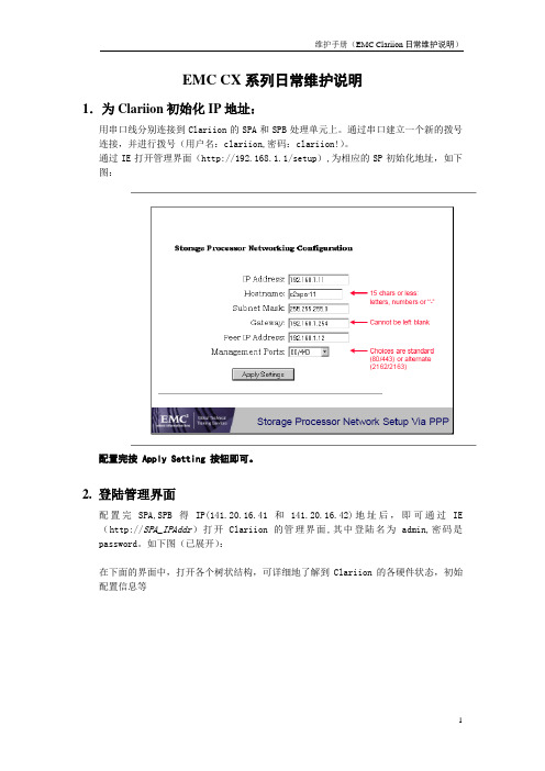
通过串口建立一个新的拨号连接,并进行拨号(用户名:clariion,密码:clariion!)。
通过IE打开管理界面(http://192.168.1.1/setup),为相应的SP初始化地址,如下图:配置完按 Apply Setting 按钮即可。
2. 登陆管理界面配置完SPA,SPB得IP(141.20.16.41和141.20.16.42)地址后,即可通过IE (http://SPA_IPAddr)打开Clariion的管理界面,其中登陆名为admin,密码是password。
如下图(已展开):在下面的界面中,打开各个树状结构,可详细地了解到Clariion的各硬件状态,初始配置信息等3. 查看错误选中存储设备,点击鼠标右键,选择Faults…,检查阵列设备是否正常工作。
4. 查看日志点中SPA或者SPB,点击鼠标右键,选择View Events5. 将日志文件存放到本地点击Save,输入要保存日志文件的路径6. 根据实际需求配置阵列:a.建立Raid Group弹出配置界面后,使用Manual 选项直接选择需要使用的disk。
b.在相应的Raid Group 上创建LUN在该选项里选择创建的Raid类型,注,每个Raid Group 只能有一种Raid类型。
c.创建Storage Group,并为主机和其所拥有的LUN建立关系,即将相应的主机和LUN加入到同一个Storage Group 中创建Storage Group 后,将相应的lun和主机加入,注,每台主机和每个LUN只能属于唯一的一个Storage Group。
EMCCLARiiON使用维护手册

EMCCLARiiON使用维护手册第一章系统日常使用规范1环境需求空气质量EMC设备须安装于空调环境中,空气的温度及湿度均可调节;如从室外补充新风,需经滤网过滤,以保证空气的洁净度。
机房温度湿度机房高度对于EMCCLARiiONCX3系统,从活动地板至天花板或吊顶的最小高度为250cm.水平高度重量设备重量因设备型号,配置的不同及产品的改进而有所不同,变化范围很大。
下表仅供参考:活动地板活动地板必须能够支撑设备的重量,包括静态单点承重及动态移动承重。
如果地板不够,地板的四角必须有坚固立柱支撑。
对于超过500公斤存储系统的安装,除满足上述要求外,承重地板需进行额外加固,在每块承重地板的中央另加立柱支撑静态单点承重静态单点承重的计算方法是:设备满配置重量(最大重量)÷承重点数量所有EMC存储设备均有4个滚轮,因此活动地板的静态单点承重=设备满配置重量÷4动态移动承重态移动承重是指设备移动时地板承受的重量动态移动承重的计算方法是:设备重量÷承重点数量除上述设备重量外,用户应根据自己的实际情况,考虑周围设备及人员活动情况,综合计算地板的承重电源容量电源应在EMC设备2米范围内;三相电源的开关每相要分离;即每相电源要使用独立的开关,以防止当某一相电源跳闸时,带动另外两相电源同时跳闸。
2管理设备为了更好的对盘阵状态进行监控,要求在机房内安装一台预装Win2000的PC并与机房网络连接。
该PC同时要求预装。
3注意事项为确保数据高可用性及安全,我公司对所有销售的EMCCLARiiON系列产品均有完善周到的售后服务,因此在设备出现硬件故障时,希望客户及时与我们联系。
如因特殊原因需客户自行进行硬件更换,必须在远程监控下完成。
同时光纤线不能被挤压,踩踏,折角不能超过90度。
所有的备用盘均应避免震动。
第二章系统启动和停止系统启动1.开启机柜电源2.开启所有与CX3-40连接的DAE电源3.开启CX3-40风扇电源模块电源4.开启SPS电源开关5.加载应用系统关闭1.停止主机所有对盘阵的I/O2.如果应用系统是UNIXOS要Umountfilesystems3.关闭SPS电源4.在SPS电源关闭后,将所有的DAE电源开关置于关闭状态5.将机柜电源关闭第三章日常监控监控工具EMCCLARiiONCX3-40可以通过EMC公司NavisphereManager软件进行日常监控,NavisphereManager可以安装在Windows2000/NT/XP平台上,可以通过网络对盘阵进行日常监控。
EMC CX系列存储日常管理维护和故障排除手册
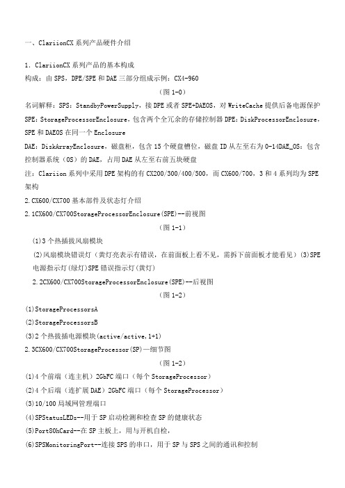
一、ClariionCX系列产品硬件介绍1.ClariionCX系列产品的基本构成构成:由SPS,DPE/SPE和DAE三部分组成示例:CX4-960(图1-0)名词解释:SPS:StandbyPowerSupply,接DPE或者SPE+DAEOS,对WriteCache提供后备电源保护SPE:StorageProcessorEnclosure,包含两个全冗余的存储控制器DPE:DiskProcessorEnclosure,SPE和DAEOS在同一个EnclosureDAE:DiskArrayEnclosure,磁盘柜,包含15个硬盘槽位,磁盘ID从左至右为0-14DAE_OS:包含控制器系统(OS)的DAE,占用DAE从左至右前五块硬盘注:Clariion系列中采用DPE架构的有CX200/300/400/500,而CX600/700,3和4系列均为SPE 架构2.CX600/CX700基本部件及状态灯介绍2.1CX600/CX700StorageProcessorEnclosure(SPE)--前视图(图1-1)(1)3个热插拔风扇模块(2)风扇模块错误灯(黄灯亮表示有错误,在前面板上看不见,需拆下前面板才能看见)(3)SPE电源指示灯(绿灯)SPE错误指示灯(黄灯)2.2CX600/CX700StorageProcessorEnclosure(SPE)--后视图(图1-2)(1)StorageProcessorsA(2)StorageProcessorsB(3)2个热拔插电源模块(active/active,1+1)2.3CX600/CX700StorageProcessor(SP)—细节图(图1-2)(1)4个前端(连主机)2GbFC端口(每个StorageProcessor)(2)4个后端(连扩展DAE)2GbFC端口(每个StorageProcessor)(3)10/100局域网管理端口(4)SPStatusLEDs--用于SP启动检测和检查SP的健康状态(5)Port80hCard--在SP主板上,用与开机自检,(6)SPSMonitoringPort--连接SPS的串口,用于SP与SPS之间的通讯和控制(7)Serial/PPPPort--获取动态IP地址进行维护或也可通过HyperTerminal软件检测SP的启动3.CX200/300/400/500基本部件及状态灯介绍3.1CX200/300/400/500DiskProcessorEnclosure(DPE)(四款产品均为DPE架构,除SP的前端和后端端口数量有差别外,基本一样,下图为CX500的DPE)(图1-4)(1)BE0–后端总线端口0(HSSDC)--连接DPE和DAE(2)BE1–后端总线端口1(HSSDC)--连接DPE和DAE(3)两个前端2Gb端口(FC)每个StorageProcessor(4)Enclosure状态灯--绿色(电源灯),黄灯(错误灯或可用于检测启动过程)(5)10/100以太网管理端口(6)SerialMgmtPort(RJ-45)--获取动态IP地址进行维护或也可通过HyperTerminal软件检测SP的启动(7)SPSMonitoringPort--连接SPS的串口,用于SP与SPS之间的通讯和控制4.CX3-10/3-20/3-40基本部件及状态灯介绍4.1CX3-10/3-20/3-40StorageProcessorEnclosure(SPE)--前视图(图1-5)(A)四个热插拔电源模块,从左至右依次为PS_A0A1B0B1(B)电源模块故障指示灯,故障时亮黄色(C)系统电源指示灯:绿色,常亮系统故障指示灯:黄色,系统故障时亮4.2CX3-10/3-20/3-40StorageProcessorEnclosure(SPE)—后视图(图1-6)4.3CX3-10/3-20/3-40StorageProcessor(SP)—细节图(三款产品均为SPE架构,除SP前端和后端端口数量有差别外,基本一样,下图为CX3-40的SP)(图1-7)A:SPS监控端口B:管理串口C:电源指示灯:绿色,常亮D:故障指示灯:黄色,故障时亮E:服务管理网口F:客户管理网口G:后端扩展端口H:前端光纤端口5.CX3-80基本部件及状态灯介绍5.1CX3-80StorageProcessorEnclosure(SPE)—前视图(图1-8)A:电源模块,上有黄色故障指示灯,故障时亮B:冷却风扇模块,上有黄色故障指示灯,故障时亮C:系统故障指示灯:黄色,故障时亮D:系统电源指示灯:绿色,常亮5.2CX3-80StorageProcessorEnclosure(SPE)—后视图(图1-9)A:电源模块B:SANManagementModuleC:I/O模块电源模块5.3CX3-80StorageProcessor(SP)—细节图(图1-10)A:SP控制器工作状态指示灯B:I/OModule5.4CX3-80I/OModule--细节图(图1-11)A:后端端口工作状态LEDB:后端端口C:前端端口D:前端端口工作状态LEDE:I/O模块电源与故障指示灯,黄色灯亮表示有故障5.5CX3-80SANManagementModule--细节图A:电源指示灯B:故障指示灯C:用户管理网络端口D:服务管理网络端口,仅限于EMC服务人员使用E:管理串口F:SPS监控端口(图1-12)6.CX4-120/240/480基本部件及状态灯介绍6.1CX4-120/240/480StorageProcessorEnclosure(SPE)—前视图(图1-13)A0:电源模块A1:电源模块B0:电源模块B1:电源模块C:CPU模块AD:CPU模块BE:CPU模块A电源和故障指示灯F:CPU模块B电源和故障指示灯G:存储系统电源和故障指示灯6.2CX4-120/240/480StorageProcessorEnclosure(SPE)—后视图(图1-14)A:ManagementModule(管理模块)B:I/OModule(I/O模块)C:Power/FaultLED(电源/故障指示灯)6.3CX4-120/240/480StorageProcessor(SP)—细节图(图1-15)A:ManagementModule(管理模块)B:BackEndPortonI/OModule(I/O模块上的后端端口,连接DAE)C:FCFrontEndPortonI/OModule(I/O模块上的前端光纤端口,连接主机)D:iSCSIFrontEndPortonI/OModule(I/O模块上的前端iSCSI端口,连接主机)6.4CX4-120/240/480ManagementModule—细节图A:ServiceLANPort(服务端口,仅限于EMC服务使用)B:ManagementLANPort(用户管理端口)C:SPSPort(SPS监控端口)D:CommunicationsPort(管理端口)E:NMI(系统维护用,勿触动)(图1-16)7.CX4-960基本部件及状态灯介绍7.1CX4-960StorageProcessorEnclosure(SPE)—前视图(图1-17)A1:PowerSupplyA(电源模块A)A2:PowerSupplyB(电源模块B)B1-B4:Blowers/Fans(风扇模块)C:EnclosureFaultLED(系统故障指示灯)D:PowerLED(系统电源指示灯)7.2CX4-960StorageProcessorEnclosure(SPE)—后视图(图1-18)A:PowerSupplyB(电源模块B)B:PowerSupplyA(电源模块A)C:ManagementModule(管理模块)D:ManagementModule(管理模块)E:I/OAnnex(I/O扩展模块)7.3CX4-960StorageProcessor(SP)—细节图(图1-19)A:PowerLED(电源指示灯)B:FaultLED(故障指示灯)C:UnsafetoRemoveLEDD1-D4:I/OModule(I/O模块)7.4CX4-960ManagementModule—细节图A:FaultLED(故障指示灯)B:PowerLED(电源指示灯)C:USBD:ManagementLANPort(以太网管理端口)E:ServiceLANPort(以太网服务端口,仅限于EMC服务人员)F:NMIButtonG:CommunicationsPort(服务端口)H:SPSPort(SPS监控端口)(图1-20)8.DiskArrayEnclosure(DAE)基本部件及状态灯介绍8.1DiskArrayEnclosure(DAE)--前视图(图1-21)(10)硬盘状态灯--绿灯表示连接状态,绿灯闪烁表示磁盘活动状态,黄灯亮表示磁盘报错(11)盘柜状态灯--绿灯表示供电正常,黄灯亮表示盘柜有错误(12)Slot0-4,共5块DAE-OSVaultDrives(仅限于DAE_OS),从左至右,Slot0--Slot48.2DiskArrayEnclosure(DAE)--后视图(图1-22)TwoLinkControlCard(LCC)(1)LCC状态灯--绿色表示电源,黄色表示有错误(2)Expansion端口(HSSDC)--灯亮表示有信号(3)光纤环路ID指示灯(LoopIDLED)--0,1,2,3,表示后端连接的光纤换路(Loop)ID(4)Primary端口(HSSDC)--灯亮表示有信号TwoDAE电源模块(5)两个集成了风扇的电源模块(6)风扇错误灯(黄色)(7)电源状态灯(绿色--有电,黄色--有错)(8)交流电源输入开关,对DAE-OS,DPE或SPE关电,应使用此开关(9)Enclosure地址开关-如是DAE-OS的Enclosure,则其必须被设置为08.3DiskArrayEnclosure2P/3P(DAE2P/3P)--后视图(图1-23)A:电源模块,下面电源模块为PSA,上面为PSBB:LCC模块,下为LCCA,上为LCCBC:PRI端口,连接SPBackEnd端口或者上级DAEEXP端口D:EXP端口,连接下级DAEPRI端口E:EnclosureIDLEDF:LoopIDLEDG:电源与故障指示灯9.StandbyPowerSupply(SPS)基本部件及状态灯介绍9.11KWIUSPS(图1-24)(1)电源开关(2)交流电源输入(3)SPE&启动盘所在DAE的交流输出(4)SPS监测端口--连接SP的串口,用于SP与SPS之间的通讯和控制(5)状态灯(从下至上)➢内部监测灯—亮黄色表示SPS内部监测出错➢更换SPS指示灯—亮黄色表示电池寿命已到或者自检出错➢电池供电指示灯--当SPS给SP或DAEOS供电时亮黄色➢电源灯--当SPS充满电后亮常绿,当SPS电池被充电时闪绿色(图1-25)A:交流输入B:交流输出C:电源开关D:SPS监测端口--连接SP的串口,用于SP与SPS之间的通讯和控制E:状态灯(从下至上)➢内部监测灯—亮黄色表示SPS内部监测出错➢更换SPS指示灯—亮黄色表示电池寿命已到或者自检出错➢电池供电指示灯--当SPS给SP或DAEOS供电时亮黄色➢电源灯--当SPS充满电后亮常绿,当SPS电池被充电时闪绿色二、如何用Navisphere看存储的状态在Navisphere中,除正常状态以外,CX磁盘阵列的四种常见状态T:一个或者多个部件处于Transition状态,比如LUN正在Rebuilding,SPS正在充电F:一个或者多个部件出现故障,注意,存储刚加电,由于SPS充电,也会出现F状态X:存储系统不可访问,比如网络连接断开等情况:当前Navishper版本不支持对该存储系统进行管理举例如下:ArrayinTransitionArrayFaultedArrayInaccessible如在Navisphere发现有报错,检查CX磁盘阵列错误的简单方法1、右击存储,选择fault,会显示具体报错信息2、展开Physical项,可以定位具体故障部件3、Clariion每个部件都有独立的故障指示灯,在Navishpere发现错误后,可以观察存储故障部件的错误指示灯进一步确认三、客户发现Clariion出现问题,应如何报修?(注:如客户已装了dial-out或者Call-home,存储会让管理工作站自动拨号并报修,若无,需客户自己发现并报修)1.获取ClariionCX系列阵列的序列号有以下五种方法:方法一:EMC工程师在存储安装时会在存储贴上写有序列号的白色标签,标签上会注明客户EMC 报修电话、SiteID、存储序列号等信息,参见下图:方法二:如安装工程师漏贴标签,注意必须查SPE或DPE上的标签(DPE架构的从机柜后面查看上图所示位置)(SPE架构的从机柜正面拆下SPE挡板,查看上图所示位置)方法三:通过serializationtag查看(仅适用于Clariion4系列产品)CX4-120/240/480请查看存储SPE后部的黑色标签,上面有产品的PN(型号),SN(序列号)CX4-960和CX4-120/240/480差不多,也是在SPE后部有一个黑色标签,只是位置不同方法四:通过Navisphere命令查看CX存储的序列号:(红色字体)Name:K10Desc:PhysicalNode:K10Signature:1912950PeerSignature:1912955SCSIId:0SPIdentifier:AModel:CX3-40cModelType:RackmountSPMemory:4096SerialNo:Cabinet:SPE3C:\ProgramFiles\EMC\NavisphereCLI>方法五:通过Navisphere图形界面查看CX存储的序列号右击存储,选择Properties,在弹出窗口General选项卡中的SerialNumber一项2.拔打EMC全球响应中心800电话报修➢注意:必须事先准备好序列号,报修时需提供存储序列号(CX系列的序列号格式基本都是CK2000开头,后跟8位数字),同时请提供具体的故障描述,如果部件故障,最好能提供故障部件的PartNumber(PN),特别是硬盘的PN,以便于服务人员准确准备备件四、EMCClariionCX系列开关机注意事项及详细步骤开机前注意事项:1.磁盘阵列在加电前,为确保磁盘柜散热和工作正常,请确认所有磁盘柜的每个槽位都已经插上硬盘和挡风板2.开机前需确保――SPE或DPE至少要有一个正常工作的SP,每个DAE都至少要一块正常工作的LCC1.检查所有供电线路联接是否正常,是否有松动或改动并改正2.从机柜顶部开始,由上至下打开所有DAE磁盘机箱的电源。
EMC Clariion 系列磁盘阵列基本配置
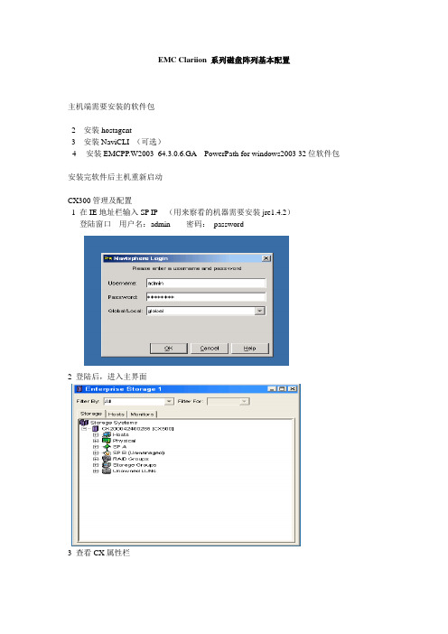
EMC Clariion 系列磁盘阵列基本配置主机端需要安装的软件包2 安装hostagent3 安装NaviCLI (可选)4安装EMCPP.W2003_64.3.0.6.GA PowerPath for windows2003 32位软件包安装完软件后主机重新启动CX300管理及配置1 在IE地址栏输入SP IP(用来察看的机器需要安装jre1.4.2)登陆窗口用户名:admin 密码:password2 登陆后,进入主界面3 查看CX属性栏4 指定Memory 大小,标准安照write cache= 2 read cache5 启用SP Cache6 启用access control enable7 查看,CX已经安装和激活的功能项8 如何建RAID—Create RAID Group; 建LUN-----Bind LUN; 建组-----Create storage GroupRAID 组构建情况0----5号盘RAID GROUP11 RAID 组上建LUN12存储组构建存储组分配主机资源和LUN资源右键点击刚创建的storagegroup,选择select lunlun0 是刚才bind lun 菜单做的,把可用的lun0 从左边转移到右边,加入到这个storage group点选luns右边的hosts把主机也加入到storagegroup.前端服务器安装了navisphere hostagent后会自动注册,在这里就能看到把可用的host 从左边转移到右边,加入到这个storage group现在这个storagegroup 中加入了一个host ,一个lun .按ok 确认后主机hzgk1就会在磁盘管理内发现一颗新的硬盘,那颗硬盘就是加入到那个storagegroup里的lun .系统启动和停止系统启动:1.开启交换机2.开启所有与CX连接的DAE电源(如果有DAE)3.开启CX电源4.开主机,加载应用系统关闭:1.停止主机所有对盘阵的I/O2.如果应用系统是UNIX OS 要Umount file systems3.关闭SPS电源4.在SPS电源关闭后,将所有的DAE电源开关置于关闭状态5.关闭交换机。
EMC CX系列存储日常管理维护和故障排除手册.
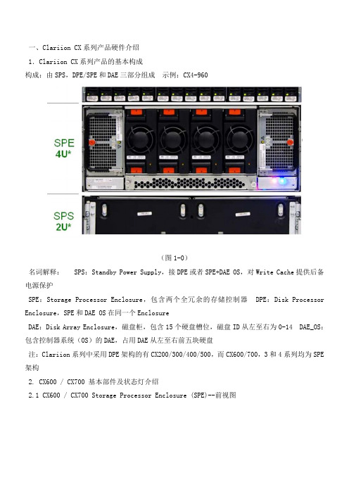
一、Clariion CX系列产品硬件介绍1.Clariion CX系列产品的基本构成构成:由SPS,DPE/SPE和DAE三部分组成示例:CX4-960(图1-0)名词解释: SPS:Standby Power Supply,接DPE或者SPE+DAE OS,对Write Cache提供后备电源保护SPE:Storage Processor Enclosure,包含两个全冗余的存储控制器 DPE:Disk Processor Enclosure,SPE和DAE OS在同一个EnclosureDAE:Disk Array Enclosure,磁盘柜,包含15个硬盘槽位,磁盘ID从左至右为0-14 DAE_OS:包含控制器系统(OS)的DAE,占用DAE从左至右前五块硬盘注:Clariion系列中采用DPE架构的有CX200/300/400/500,而CX600/700,3和4系列均为SPE 架构2. CX600 / CX700 基本部件及状态灯介绍2.1 CX600 / CX700 Storage Processor Enclosure (SPE)--前视图(图1-1)(1) 3个热插拔风扇模块(2) 风扇模块错误灯(黄灯亮表示有错误,在前面板上看不见,需拆下前面板才能看见) (3) SPE 电源指示灯(绿灯) SPE 错误指示灯 (黄灯)2.2 CX600 / CX700 Storage Processor Enclosure (SPE)--后视图(图1-2)(1) Storage Processors A(2) Storage Processors B(3) 2个热拔插电源模块 (active/active, 1+1)2.3 CX600 / CX700 Storage Processor (SP)—细节图(图1-2)(1) 4 个前端(连主机)2Gb FC 端口(每个 Storage Processor )(2) 4个后端(连扩展DAE)2Gb FC端口(每个 Storage Processor )(3) 10/100 局域网管理端口(4) SP Status LEDs--用于SP启动检测和检查SP的健康状态(5) Port80h Card--在SP主板上,用与开机自检,(6) SPS Monitoring Port--连接SPS的串口,用于SP与SPS之间的通讯和控制(7) Serial/PPP Port--获取动态IP地址进行维护或也可通过HyperTerminal软件检测SP的启动3. CX200 / 300 / 400 / 500 基本部件及状态灯介绍3.1 CX200 / 300 / 400 / 500 Disk Processor Enclosure (DPE)(四款产品均为DPE架构,除 SP的前端和后端端口数量有差别外,基本一样,下图为CX500的DPE)(图1-4)(1) BE0 –后端总线端口0(HSSDC)--连接DPE和DAE(2) BE1 –后端总线端口1(HSSDC)--连接DPE和DAE(3) 两个前端 2Gb 端口(FC) 每个Storage Processor(4) Enclosure 状态灯--绿色(电源灯),黄灯(错误灯或可用于检测启动过程)(5) 10/100 以太网管理端口(6) Serial Mgmt Port (RJ-45)--获取动态IP地址进行维护或也可通过HyperTerminal软件检测SP的启动(7) SPS Monitoring Port--连接SPS的串口,用于SP与SPS之间的通讯和控制4. CX3-10 / 3-20 / 3-40基本部件及状态灯介绍4.1 CX3-10 / 3-20 / 3-40 Storage Processor Enclosure (SPE)--前视图(图1-5)(A) 四个热插拔电源模块,从左至右依次为PS_A0 A1 B0 B1(B) 电源模块故障指示灯,故障时亮黄色(C) 系统电源指示灯:绿色,常亮系统故障指示灯:黄色,系统故障时亮4.2 CX3-10 / 3-20 / 3-40 Storage Processor Enclosure (SPE)—后视图(图1-6)4.3 CX3-10 / 3-20 / 3-40 Storage Processor (SP)—细节图(三款产品均为SPE架构,除 SP 前端和后端端口数量有差别外,基本一样,下图为CX3-40的SP)(图1-7)A:SPS监控端口B:管理串口C:电源指示灯:绿色,常亮D:故障指示灯:黄色,故障时亮E:服务管理网口F:客户管理网口G:后端扩展端口H:前端光纤端口5. CX3-80基本部件及状态灯介绍5.1 CX3-80 Storage Processor Enclosure (SPE)—前视图(图1-8)A:电源模块,上有黄色故障指示灯,故障时亮B:冷却风扇模块,上有黄色故障指示灯,故障时亮C:系统故障指示灯:黄色,故障时亮D:系统电源指示灯:绿色,常亮5.2 CX3-80 Storage Processor Enclosure (SPE)—后视图(图1-9)A:电源模块B:SAN Management ModuleC:I/O 模块电源模块5.3 CX3-80 Storage Processor (SP)—细节图(图1-10)A:SP控制器工作状态指示灯B:I/O Module5.4 CX3-80 I/O Module --细节图(图1-11)A:后端端口工作状态LEDB:后端端口C:前端端口D:前端端口工作状态LEDE:I/O模块电源与故障指示灯,黄色灯亮表示有故障5.5 CX3-80 SAN Management Module --细节图A:电源指示灯B:故障指示灯C:用户管理网络端口D:服务管理网络端口,仅限于EMC服务人员使用E:管理串口F:SPS监控端口(图1-12)6. CX4-120 / 240 / 480 基本部件及状态灯介绍6.1 CX4-120 / 240 / 480 Storage Processor Enclosure (SPE)—前视图(图1-13)A0:电源模块A1:电源模块B0:电源模块B1:电源模块C:CPU模块AD:CPU模块BE:CPU模块A电源和故障指示灯F:CPU模块B电源和故障指示灯G:存储系统电源和故障指示灯6.2 CX4-120 / 240 / 480 Storage Processor Enclosure (SPE)—后视图(图1-14)A:Management Module(管理模块)B:I/O Module(I/O模块)C:Power / Fault LED(电源/故障指示灯)6.3 CX4-120 / 240 / 480 Storage Processor (SP)—细节图(图1-15)A:Management Module(管理模块)B:Back End Port on I/O Module(I/O模块上的后端端口,连接DAE)C:FC Front End Port on I/O Module(I/O模块上的前端光纤端口,连接主机)D:iSCSI Front End Port on I/O Module(I/O模块上的前端iSCSI端口,连接主机)6.4 CX4-120 / 240 / 480 Management Module—细节图A:Service LAN Port(服务端口,仅限于EMC服务使用)B:Management LAN Port(用户管理端口)C:SPS Port(SPS监控端口)D:Communications Port(管理端口)E:NMI(系统维护用,勿触动)(图1-16)7. CX4-960基本部件及状态灯介绍7.1 CX4-960 Storage Processor Enclosure (SPE)—前视图(图1-17)A1:Power Supply A(电源模块A)A2:Power Supply B(电源模块B)B1-B4:Blowers / Fans(风扇模块)C:Enclosure Fault LED(系统故障指示灯)D:Power LED(系统电源指示灯)7.2 CX4-960 Storage Processor Enclosure (SPE)—后视图(图1-18)A:Power Supply B(电源模块B)B:Power Supply A(电源模块A)C:Management Module(管理模块)D:Management Module(管理模块)E:I/O Annex(I/O扩展模块)7.3 CX4-960 Storage Processor (SP)—细节图(图1-19)A:Power LED(电源指示灯)B:Fault LED(故障指示灯)C:Unsafe to Remove LED D1-D4:I/O Module(I/O模块)7.4 CX4-960 Management Module—细节图A:Fault LED(故障指示灯)B:Power LED(电源指示灯)C:USBD:Management LAN Port(以太网管理端口)E:Service LAN Port(以太网服务端口,仅限于EMC服务人员)F:NMI ButtonG:Communications Port(服务端口)H:SPS Port(SPS 监控端口)(图1-20)8. Disk Array Enclosure (DAE)基本部件及状态灯介绍8.1 Disk Array Enclosure (DAE) --前视图(图1-21)(10) 硬盘状态灯--绿灯表示连接状态,绿灯闪烁表示磁盘活动状态,黄灯亮表示磁盘报错 (11) 盘柜状态灯--绿灯表示供电正常,黄灯亮表示盘柜有错误(12) Slot0-4 ,共5块DAE-OS Vault Drives (仅限于DAE_OS),从左至右,Slot 0--Slot4 8.2 Disk Array Enclosure (DAE) --后视图(图1-22)Two Link Control Card (LCC)(1) LCC 状态灯--绿色表示电源,黄色表示有错误(2) Expansion 端口(HSSDC)--灯亮表示有信号(3) 光纤环路ID指示灯( Loop ID LED)--0,1,2,3, 表示后端连接的光纤换路(Loop) ID (4) Primary 端口(HSSDC)--灯亮表示有信号 Two DAE电源模块(5) 两个集成了风扇的电源模块(6) 风扇错误灯(黄色)(7) 电源状态灯(绿色--有电,黄色--有错)(8) 交流电源输入开关,对DAE-OS,DPE或SPE关电,应使用此开关(9) Enclosure 地址开关-如是DAE-OS的Enclosure,则其必须被设置为08.3 Disk Array Enclosure 2P/3P (DAE 2P/3P) --后视图(图1-23)A:电源模块,下面电源模块为PS A,上面为PS BB:LCC模块,下为LCC A,上为LCC BC:PRI端口,连接SP Back End端口或者上级DAE EXP端口D:EXP端口,连接下级DAE PRI端口E:Enclosure ID LED F:Loop ID LEDG:电源与故障指示灯9. Standby Power Supply (SPS) 基本部件及状态灯介绍9.1 1 KW I U SPS(图1-24)(1) 电源开关(2) 交流电源输入(3) SPE & 启动盘所在DAE的交流输出(4) SPS 监测端口--连接SP的串口,用于SP与SPS之间的通讯和控制(5) 状态灯 (从下至上)内部监测灯—亮黄色表示SPS内部监测出错更换SPS指示灯—亮黄色表示电池寿命已到或者自检出错电池供电指示灯--当SPS给SP或DAE OS供电时亮黄色电源灯--当SPS充满电后亮常绿,当SPS电池被充电时闪绿色9.2 2.2KW 2U SPS(图1-25)A:交流输入B:交流输出C:电源开关D:SPS监测端口--连接SP的串口,用于SP与SPS之间的通讯和控制E:状态灯(从下至上)内部监测灯—亮黄色表示SPS内部监测出错更换SPS指示灯—亮黄色表示电池寿命已到或者自检出错电池供电指示灯--当SPS给SP或DAE OS供电时亮黄色电源灯--当SPS充满电后亮常绿,当SPS电池被充电时闪绿色二、如何用 Navisphere看存储的状态在 Navisphere 中,除正常状态以外,CX 磁盘阵列的四种常见状态T:一个或者多个部件处于Transition状态,比如LUN正在Rebuilding,SPS正在充电 F:一个或者多个部件出现故障,注意,存储刚加电,由于SPS充电,也会出现F状态X:存储系统不可访问,比如网络连接断开等情况?:当前Navishper版本不支持对该存储系统进行管理举例如下:Array in TransitionArray FaultedArray Inaccessible如在 Navisphere 发现有报错,检查 CX磁盘阵列错误的简单方法1、右击存储,选择fault,会显示具体报错信息2、展开Physical项,可以定位具体故障部件3、Clariion每个部件都有独立的故障指示灯,在Navishpere发现错误后,可以观察存储故障部件的错误指示灯进一步确认三、客户发现 Clariion出现问题,应如何报修?(注:如客户已装了 dial-out或者Call-home, 存储会让管理工作站自动拨号并报修,若无,需客户自己发现并报修)1.获取 Clariion CX系列阵列的序列号有以下五种方法:方法一:EMC 工程师在存储安装时会在存储贴上写有序列号的白色标签,标签上会注明客户EMC报修电话、Site ID 、存储序列号等信息,参见下图:方法二:如安装工程师漏贴标签,注意必须查SPE或DPE上的标签(DPE架构的从机柜后面查看上图所示位置)(SPE架构的从机柜正面拆下SPE挡板,查看上图所示位置)方法三:通过serialization tag查看(仅适用于Clariion 4系列产品) CX4-120/240/480请查看存储SPE后部的黑色标签,上面有产品的PN(型号),SN(序列号)CX4-960 和CX4-120/240/480差不多,也是在SPE后部有一个黑色标签,只是位置不同方法四:通过 Navisphere命令查看 CX存储的序列号:(红色字体)C:\Program Files\EMC\Navisphere CLI>navicli -h 192.168.2.164 getagentName: K10 Desc:Node: A-CK200072300124Physical Node: K10Signature: 1912950Peer Signature: 1912955SCSI Id: 0SP Identifier: ARevision: 3.26.40.5.016Model: CX3-40cModel Type: RackmountProm Rev: 3.58.00SP Memory: 4096Serial No: CK200072300124Cabinet: SPE3 C:\Program Files\EMC\Navisphere CLI>方法五:通过 Navisphere图形界面查看 CX存储的序列号右击存储,选择Properties,在弹出窗口General选项卡中的Serial Number一项2.拔打 EMC 全球响应中心 800电话报修如用固定电话报修,请拔打 8008190009如用手机报修,请拔打4006700009 请依照语音提示进行报修注意:必须事先准备好序列号,报修时需提供存储序列号( CX系列的序列号格式基本都是 CK2000开头,后跟 8位数字),同时请提供具体的故障描述,如果部件故障,最好能提供故障部件的Part Number(PN),特别是硬盘的PN,以便于服务人员准确准备备件四、EMC Clariion CX系列开关机注意事项及详细步骤开机前注意事项:1. 磁盘阵列在加电前,为确保磁盘柜散热和工作正常,请确认所有磁盘柜的每个槽位都已经插上硬盘和挡风板2. 开机前需确保――SPE或 DPE至少要有一个正常工作的 SP,每个 DAE都至少要一块正常工作的 LCC1. 检查所有供电线路联接是否正常,是否有松动或改动并改正2. 从机柜顶部开始,由上至下打开所有 DAE磁盘机箱的电源。
使用维护手册

EMC CLARiiON使用维护手册第一章系统日常使用规范1环境需求空气质量EMC设备须安装于空调环境中,空气的温度及湿度均可调节;如从室外补充新风,需经滤网过滤,以保证空气的洁净度。
机房温度湿度机房高度对于EMC CLARiiON CX3系统,从活动地板至天花板或吊顶的最小高度为250cm.水平高度重量设备重量因设备型号,配置的不同及产品的改进而有所不同,变化范围很大。
下表仅供活动地板活动地板必须能够支撑设备的重量,包括静态单点承重及动态移动承重。
如果地板不够,地板的四角必须有坚固立柱支撑。
对于超过500公斤存储系统的安装,除满足上述要求外,承重地板需进行额外加固,在每块承重地板的中央另加立柱支撑静态单点承重静态单点承重的计算方法是:设备满配置重量(最大重量)÷承重点数量所有EMC存储设备均有4个滚轮,因此活动地板的静态单点承重=设备满配置重量÷ 4动态移动承重态移动承重是指设备移动时地板承受的重量动态移动承重的计算方法是:设备重量÷承重点数量除上述设备重量外,用户应根据自己的实际情况,考虑周围设备及人员活动情况,综合计算地板的承重电源容量的开关,以防止当某一相电源跳闸时,带动另外两相电源同时跳闸。
2管理设备为了更好的对盘阵状态进行监控,要求在机房内安装一台预装Win2000 的PC并与机房网络连接。
该PC 同时要求预装JRE 1.4。
3注意事项为确保数据高可用性及安全,我公司对所有销售的EMC CLARiiON 系列产品均有完善周到的售后服务,因此在设备出现硬件故障时,希望客户及时与我们联系。
如因特殊原因需客户自行进行硬件更换,必须在远程监控下完成。
同时光纤线不能被挤压,踩踏,折角不能超过90度。
所有的备用盘均应避免震动。
第二章系统启动和停止系统启动1.开启机柜电源2.开启所有与CX3-40连接的DAE电源3.开启CX3-40风扇电源模块电源4.开启SPS电源开关5.加载应用系统关闭1.停止主机所有对盘阵的I/O2.如果应用系统是UNIX OS 要Umount file systems3.关闭SPS电源4.在SPS电源关闭后,将所有的DAE电源开关置于关闭状态5.将机柜电源关闭第三章日常监控监控工具EMC CLARiiON CX3-40可以通过EMC公司Navisphere Manager软件进行日常监控,Navisphere Manager 可以安装在Windows 2000/NT/XP 平台上,可以通过网络对盘阵进行日常监控。
EMC CX系列磁阵安装与维护手册
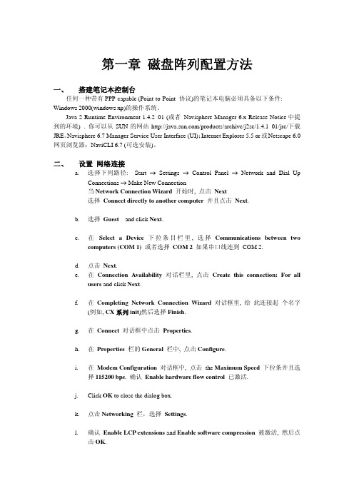
3. 连接成功后,打开一个网页,地址栏输入192.168.1.1/setup后,回车. 4. 此时回出现类似下图的界面:
l. 确认 Enable LCP extensions and Enable software compression 被激活, 然后点 击 OK.
m. 选中 Internet Protocol (TCP/IP) 后设置属性. 设置自动获取IP地址,DNS服务器地址. 相关参数设置表如下:
Line characteristic 设置
users and click Next.
f. 在 Completing Network Connection Wizard 对话框里, 给 此连接起 个名字 (例如, CX 系列 init)然后选择 Finish.
g. 在 Connect 对话框中点击 Properties.
h. 在 Properties 栏的 General 栏中, 点击 Configure.
七、 使用 Manager (Rev. 6.x) 创建 STORAGE GROUP
在 Navisphere 6.x 下, 通过以下步骤创建 storage group: a. 鼠标右击 storage-system 图标, 然后选择 Create Storage Groups.
b. 为此 Storage Group 创建一个新名字.
重要提示: 同一个 RAID 组的的所有磁盘必须是相同容量的的同等规格的磁盘. 而 hot
spare 盘必须大于或等于磁盘阵列中所有硬盘的容量. 3.被选的磁盘会呈现出来以供选择
EMC CX700 日常维护指南
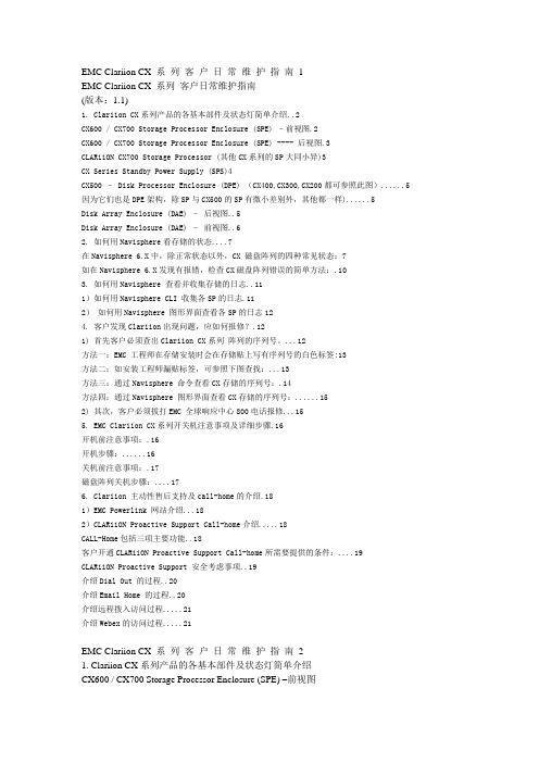
EMC Clariion CX 系列客户日常维护指南1EMC Clariion CX 系列客户日常维护指南(版本:1.1)1. Clariion CX系列产品的各基本部件及状态灯简单介绍..2CX600 / CX700 Storage Processor Enclosure (SPE) –前视图.2CX600 / CX700 Storage Processor Enclosure (SPE) ---- 后视图.3CLARiiON CX700 Storage Processor (其他CX系列的SP大同小异)3CX Series Standby Power Supply (SPS)4CX500 – Disk Processor Enclosure (DPE) (CX400,CX300,CX200都可参照此图) (5)因为它们也是DPE架构,除SP与CX500的SP有微小差别外,其他都一样) (5)Disk Array Enclosure (DAE) –后视图..5Disk Array Enclosure (DAE) –前视图..62. 如何用Navisphere看存储的状态 (7)在Navisphere 6.X中,除正常状态以外,CX 磁盘阵列的四种常见状态:7如在Navisphere 6.X发现有报错,检查CX磁盘阵列错误的简单方法:.103. 如何用Navisphere 查看并收集存储的日志..111)如何用Navisphere CLI 收集各SP的日志.112)如何用Navisphere 图形界面查看各SP的日志124. 客户发现Clariion出现问题,应如何报修?.121) 首先客户必须查出Clariion CX系列阵列的序列号。
(12)方法一:EMC 工程师在存储安装时会在存储贴上写有序列号的白色标签:13方法二:如安装工程师漏贴标签,可参照下图查找: (13)方法三:通过Navisphere 命令查看CX存储的序列号:.14方法四:通过Navisphere 图形界面查看CX存储的序列号: (15)2) 其次,客户必须拔打EMC 全球响应中心800电话报修 (15)5. EMC Clariion CX系列开关机注意事项及详细步骤.16开机前注意事项:.16开机步骤: (16)关机前注意事项:.17磁盘阵列关机步骤: (17)6. Clariion 主动性售后支持及call-home的介绍.181)EMC Powerlink 网站介绍 (18)2)CLARiiON Proactive Support Call-home介绍 (18)CALL-Home包括三项主要功能..18客户开通CLARiiON Proactive Support Call-home所需要提供的条件: (19)CLARiiON Proactive Support 安全考虑事项..19介绍Dial Out 的过程..20介绍Email Home 的过程..20介绍远程拨入访问过程 (21)介绍Webex的访问过程 (21)EMC Clariion CX 系列客户日常维护指南21. Clariion CX系列产品的各基本部件及状态灯简单介绍CX600 / CX700 Storage Processor Enclosure (SPE) –前视图(1) 3个可热插拔的风扇模块(2) 风扇模块错误灯(黄灯亮表示有错误,面板上看不见,需拆下面板才能看见)(3) SPE 电源指示灯(绿灯)SPE 错误指示灯(黄灯)EMC Clariion CX 系列客户日常维护指南3CX600 / CX700 Storage Processor Enclosure (SPE) ---- 后视图1. Storage Processors A2. Storage Processors B3. 2个可热拔插的电源(active/active, n+1)CLARiiON CX700 Storage Processor (其他CX系列的SP大同小异)(1) 4 个前端(连主机)2Gb FC 端口,每个Storage Processor(2) 4个后端(连磁盘柜DAE)2Gb FC 端口(3) 10/100 局域网管理端口(4) SP Status LEDs――用于SP启动检测和检查SP的健康状态(5) Port80h Card―――在SP主板上,用与开机自检,EMC Clariion CX 系列客户日常维护指南4(6) SPS Monitoring Port----连接SPS的串口,用于SP与SPS之间的通讯和控制(7) S erial/PPP Port――获取动态IP地址进行维护或也可通过HyperTerminal软件检测SP的启动CX Series Standby Power Supply (SPS)(1) 电源开关(2) 交流电源输入(3) SPE & 启动盘所在DAE的交流输出(4) SPS 监测端口---连接SP的串口,用于SP与SPS之间的通讯和控制(5) 状态灯(从下至上)错误灯-当SPS出错时亮黄色电池放电灯-SPS放电时亮黄色电池供电灯-当SPS给SP或DAE OS供电时亮黄色电源灯-当SPS被满充电后亮常绿,当SPS电池被充电时闪绿色EMC Clariion CX 系列客户日常维护指南5CX500 – Disk Processor Enclosure (DPE) (CX400,CX300,CX200都可参照此图)因为它们也是DPE架构,除SP与CX500的SP有微小差别外,其他都一样)(1) BE0 –后端总线端口0(HSSDC)----连接DPE和DAE(2) BE1 –后端总线端口1(HSSDC)----连接DPE和DAE(3) 两个前端2Gb 端口(FC) 每个Storage Processor(4) Enclosure 状态灯-绿色(电源灯),黄灯(错误灯或可用于检测启动过程)(5) 10/100 以太网管理端口(6) Serial Mgmt Port (RJ-45)-获取动态IP地址进行维护或也可通过HyperTerminal软件检测SP的启动(7) SPS Monitoring Port-连接SPS的串口,用于SP与SPS之间的通讯和控制Disk Array Enclosure (DAE) –后视图EMC Clariion CX 系列客户日常维护指南6Two Link Control Card (LCC)(1) LCC 状态灯-绿色表示电源,黄色表示有错误(2) Expansion 端口(HSSDC)---灯亮表示有信号(3) 光纤环路ID指示灯(Loop ID LED)----0,1,2,3, 表示后端连接的光纤换路(Loop) ID(4) Primary 端口(HSSDC)---灯亮表示有信号Two DAE 电源模块(5) 两个集成了风扇的电源模块(6) 风扇错误灯(黄色)(7) 电源状态灯(绿色-有电,黄色-有错)(8) 交流电源输入开关,对DAE-OS,DPE或SPE关电,应使用此开关(9) Enclosure 地址开关-如是DAE-OS的Enclosure,则其必须被设置为0Disk Array Enclosure (DAE) –前视图盘柜――共可容纳15个双端口的磁盘(10) 硬盘状态灯-绿灯表示连接状态,闪烁表示磁盘活动状态-黄灯表示磁盘报错(11) 盘柜状态灯-绿灯表示供电正常,黄灯表示盘柜有错误(12) Slot0-4 ,共5块DAE-OS V ault Drives (CX-2GBDAE-OS Only)EMC Clariion CX 系列客户日常维护指南72. 如何用Navisphere看存储的状态在Navisphere 6.X中,除正常状态以外,CX 磁盘阵列的四种常见状态:具体举例如下:EMC Clariion CX 系列客户日常维护指南8EMC Clariion CX 系列客户日常维护指南9EMC Clariion CX 系列客户日常维护指南10如在Navisphere 6.X发现有报错,检查CX磁盘阵列错误的简单方法:EMC Clariion CX 系列客户日常维护指南113. 如何用Navisphere 查看并收集存储的日志1)如何用Navisphere CLI 收集各SP的日志EMC Clariion CX 系列客户日常维护指南122)如何用Navisphere 图形界面查看各SP的日志4. 客户发现Clariion出现问题,应如何报修?(注:如客户已装了dial-out Call-home, 存储会让管理工作站自动拨号并报修,若无,需客户自己发现并报修)1) 首先客户必须查出Clariion CX系列阵列的序列号。
EMC_CLARiiON硬件及维护指南
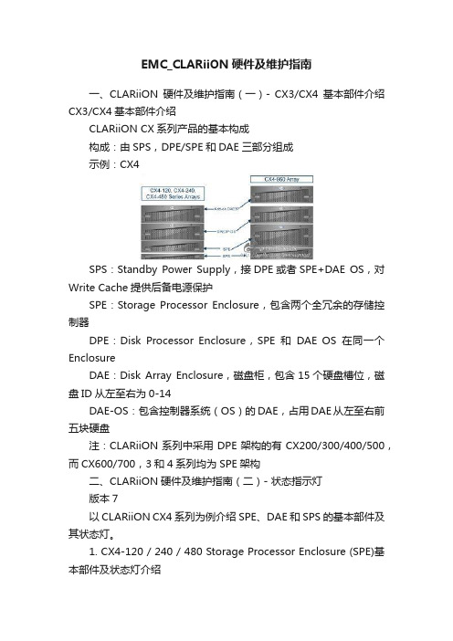
EMC_CLARiiON硬件及维护指南一、CLARiiON硬件及维护指南(一)- CX3/CX4基本部件介绍CX3/CX4基本部件介绍CLARiiON CX系列产品的基本构成构成:由SPS,DPE/SPE和DAE三部分组成示例:CX4SPS:Standby Power Supply,接DPE或者SPE+DAE OS,对Write Cache提供后备电源保护SPE:Storage Processor Enclosure,包含两个全冗余的存储控制器DPE:Disk Processor Enclosure,SPE和DAE OS在同一个EnclosureDAE:Disk Array Enclosure,磁盘柜,包含15个硬盘槽位,磁盘ID从左至右为0-14DAE-OS:包含控制器系统(OS)的DAE,占用DAE从左至右前五块硬盘注:CLARiiON系列中采用DPE架构的有CX200/300/400/500,而CX600/700,3和4系列均为SPE架构二、CLARiiON硬件及维护指南(二)- 状态指示灯版本7以CLARiiON CX4系列为例介绍SPE、DAE和SPS的基本部件及其状态灯。
1. CX4-120 / 240 / 480 Storage Processor Enclosure (SPE)基本部件及状态灯介绍1.1 SPE前视图A0,A1,B0&B1:电源模块C&D:CPU模块A和BE:CPU模块A电源和故障指示灯,黄色灯亮表示有故障F:CPU模块B电源和故障指示灯,黄色灯亮表示有故障G:存储系统电源和故障指示灯,黄色灯亮表示有故障1.2 SPE后视图A&B:管理模块和I/O模块C:电源/故障指示灯,黄色灯亮表示有故障1.3 SP细节图A:管理模块B: I/O模块上的后端端口,连接DAEC&D: I/O模块上的前端光纤端口和前端iSCSI端口,连接主机2. CX4-960 Storage Processor Enclosure (SPE)基本部件及状态灯介绍2.1 SPE前视图A1&A2:电源模块A和BB1-B4:风扇模块C:磁盘柜系统故障指示灯D:系统电源指示灯2.2 SPE后视图A&B:电源模块B和AC&D:管理模块E: I/O扩展模块2.3 SP细节图A:电源指示灯,绿色,常亮B:故障指示灯,黄色,故障时亮C:勿拔提醒指示灯D1-D4: I/O模块3. Disk Array Enclosure (DAE) 基本部件及状态灯介绍3.1 DAE前视图A: 硬盘状态灯--绿灯表示连接状态,绿灯闪烁表示磁盘活动状态,黄灯亮表示磁盘报错B: 盘柜状态灯--绿灯表示供电正常,黄灯亮表示盘柜有报错C: 插槽共5块DAE-OS Vault Drives (仅限于DAE_OS),从左至右,Slot 0--Slot 4 3.2 DAE 2P/3P后视图-适用于CX4-120/240/480/960A:电源模块,下面电源模块为PS A,上面为PS BB:LCC模块,下为LCC A,上为LCC BC:PRI端口,连接SP 后端端口(Back end port)或者上级DAE的扩展端口(EXP port)D:EXP端口,连接下级DAE端口E:磁盘柜标识(Enclosure ID)指示灯F:环路标识(Loop ID)指示灯G: 电源与故障指示灯4. Standby Power Supply (SPS) 基本部件及状态灯介绍4.1 SPS型号1 KW I U -适用于CX4-120/240/480(1) 电源开关(2&3) 交流电源输入和输出(4) SPS 监测端口--连接SP的串口,用于SP与SPS之间的通讯和控制(5) 状态灯 (从下至上)内部监测灯—亮黄色表示SPS内部监测出错更换SPS指示灯—亮黄色表示电池寿命已到或者自检出错电池供电指示灯--当SPS给SP或DAE OS供电时亮黄色电源灯--当SPS充满电后亮常绿,当SPS电池被充电时闪绿色4.2 SPS型号2.2KW 2U-适用于CX4-960A&B:交流输入和输出C:电源开关D:SPS监测端口--连接SP的串口,用于SP与SPS之间的通讯和控制E:状态灯 (从下至上)内部监测灯—亮黄色表示SPS内部监测出错更换SPS指示灯—亮黄色表示电池寿命已到或者自检出错电池供电指示灯--当SPS给SP或DAE OS供电时亮黄色电源灯--当SPS充满电后亮常绿,当SPS电池被充电时闪绿色三、CLARiiON硬件及维护指南(三)- Navisphere图形管理界面Navisphere图形管理界面适用于运行Flare版本19到29之间的CLARiiON。
EMC_CLARiiON_CX系列培训文档
EMC 保密资料 — 仅供培训使用
‹#›
© 2008 EMC Corporation.保留所有权利。
CX700 Storage Processor Enclosure (SPE)--后视图
1 2 3
SPA SPB
2个热拔插电源模块 (两个电源同时处于Active状态)
EMC 保密资料 — 仅供培训使用
D为EXP端口,连接下级DAE PRI端口
EMC 保密资料 — 仅供培训使用
‹#›
© 2008 EMC Corporation.保留所有权利。
Disk Array Enclosure 2P/3P (DAE 2P/3P) --后视图
1
2 3
E为Enclosure ID LED
F为光纤环路ID (Loop ID) G为电源与故障指示灯
‹#›
© 2008 EMC Corporation.保留所有权利。
Disk Array Enclosure 2P/3P (DAE 2P/3P) --后视图
1
2 3 4
A为电源模块,下面电源模块为PS A,上面为PS B
B为LCC模块,下为LCC A,上为LCC B C为PRI端口,连接SP 后端光纤端口或者上级DAE EXP端口
Disk Array Enclosure (DAE) --前视图
10 11 12
硬盘状态灯--绿灯表示连接状态,绿灯闪烁表示磁盘活动状态,黄灯亮表示磁盘报错 盘柜状态灯--绿灯表示供电正常,黄灯亮表示盘柜有错误
Disk0-4 -- DAE-OS (仅限于DAE-OS)
EMC 保密资料 — 仅供培训使用
介绍SPS基本部件及状态灯
1
状态灯(从下至上)
EMC项目安装通用手册
EMC存储系统安装通用手册时间:2004年11月15日目录EMC CLARiiON CX500安装与配置 (2)1.系统初始化 (2)2.在Manager中按照下列步骤创建RAID Groups (2)3. 使用Manager在RAID Groups 创建LUN (3)4. 创建Storage Groups 并连接主机到Manager (4)EMC设备维护简要手册 (5)EMC CLARiiON CX500安装与配置1.系统初始化(随箱配的串口线插入CX500的SPA的串口)a.在laptop端,选择Start →Settings →Network and Dial up Connections。
b.建立Dial up networking时选择连接名称。
c.在Connect to对话框,以用户名clariion,密码clariion!登录。
忽略Domain一栏。
点击 Connect。
d.打开Internet Explorer 或Netscape browser,键入下列URL:192.168.1.1/setupe.当屏幕出现Storage Processor Network Configuration,为SP A输入下列已经定义好的信息:IP addressHostnameSubnet maskGateway address for SP APeer IP address for SP Bf.点击 Apply Settings。
g.稍作等待后,确认屏幕出现,并提示重启SP A(必须在SP A 重启结束后才能继续),SP B的安装同上。
2.在Manager中按照下列步骤创建RAID Groupsa.说明CCA activity来决定RAID groups 的数量和类型。
b.在Navisphere 6.x中,在Enterprise Storage 栏右击Storage System图标,然后点击 Create RAID Groups。
EMC--CX系列安装及配置

• Special characters such as dots, spaces, or underscores are
• not allowed. Examples: Array1-A, Array1-B.
• IP Address _______________ _______________
• Subnet Mask _______________ ______________
EMC CLARiiON安装与配置 5
Step 1 Gather Network Information
SP-A
SP-B
• Hostname _______________ _______________
• Up to 15 alphanumeric characters. Dashes are acceptable.
• Gateway _______________ ______________
EMC CLARiiON安装与配置 6
Step 2 Verify Power Supply Setting
1. Remove the disk drive fan pack. 2. Confirm that the power switch on each power supply behind the
EMC CLARiiON安装与配置 4
Before You Start
5. Have the network administrator at your facility set up IP addresses for the FC4700
6. Make sure that the latest revisions of Navisphere Manager and Event Monitor are installed on the Windows 2000 or Windows NT host you will use as the Navisphere management station.
CLARiiON CX4-120 Setup Guide -- A03
EMC® CLARiiON® CX4-120 Setup GuideP/N 300-007-006REV. A03NoticeCopyright © 2008 EMC Corporation. All rights reserved.Published November, 2008EMC believes the information in this publication is accurate as of its publication date. The information is subject to change without notice.THE INFORMATION IN THIS PUBLICATION IS PROVIDED “AS IS.” EMC CORPORATION MAKES NO REPRESENTATIONS OR WARRANTIES OF ANY KIND WITH RESPECT TO THE INFORMATION IN THIS PUBLICATION, AND SPECIFICALLY DISCLAIMS IMPLIED WARRANTIES OF MERCHANTABILITY OR FITNESS FOR A PARTICULAR PURPOSE.Use, copying, and distribution of any EMC software described in this publication requires an applicable software license.For the most up-to-date regulatory document for your product line, go to the Technical Documentation and Advisories section on EMC Powerlink.For the most up-to-date listing of EMC product names, see EMC Corporation Trademarks on .All other trademarks used herein are the property of their respective owners.This guide explains how to install and initialize a CX4-120 storage system in a Windows environment. Steps include:•Preparing your site, planning the network configuration, and verifying your environment•Connecting to a management station and initializing the system•Readying every server that will connect to the storage system•Verifying the system and failover configurationsIf you do not already have a Powerlink® account, we strongly recommend that you go to and set one up immediately. The Powerlink website is your portal to the latest documentation and troubleshooting information, user-customized documentation specific to your configuration, and utilities and wizards required for the installation, such as the E-Lab™ Interoperability Navigator and the Navisphere Service Taskbar. Use the search feature to navigate the website. If you are installing the storage system in an environment other than Windows (such as Linux, AIX, HP-UX, or Solaris), visit the CLARiiON Tools page or the Technical Documentation and Advisories sections of the EMC Powerlink website:.Verify that your facility has the following:❒Adequate network support to provide each storage processor (SP) management port with a discrete Ethernet connection and IP address.❒Appropriate electrical wiring in place to accommodate your installation’s power cables. To support all of the storage system’s high-availability features, you must receive power from at least two separate circuits.Detailed technical specifications for CX4 series systems, including AC power requirements, are available on Powerlink.❒ A Windows workstation available on the same subnet as the storage system’s management ports. You will use this host:•To initialize the storage system•As a Navisphere® management station❒CAT 5e or better Ethernet LAN cables (one per SP) for storage-system management connections.❒At least four fiber-optic cables for connection to a Fibre Channel switch or host bus adapter.❒At least four CAT 5e or better Ethernet LAN cables for iSCSI data transmission.With your network administrator, determine the IP addresses and network parameters you plan to use with the storage system, and record the information on the following worksheet. You must have this information to set up and initialize the system.You manage the storage system through a dedicated LAN port on each storage processor. These ports must share a subnet with the host you use to initialize the system. After initialization, any host on the same network and with a supported browser can manage the system through the management ports.To connect your storage system to an iSCSI network, you need to configure servers and target storage systems in IP networks that use the iSCSI protocol. EMC supports a variety of configurations, but recommends discrete networks that are dedicated to iSCSI data traffic.Each storage processor has at least two iSCSI ports for connecting the storage system – either directly or through a network – to network interface cards (NICs) or iSCSI host bus adapters (HBAs) in a server. The iSCSI data ports on the SPs are often called targets; ports on NICs and iSCSI HBAs are iSCSI initiators.In a server with multiple NICs or iSCSI HBAs that are connected directly to the storage system, or that are on a dedicated iSCSI network, each initiator port must be on a separate subnet.Record network information for your system on the worksheet on the next page. Your network administrator should provide most of this information. For more information, refer to your configuration planning guide.IPv4 management port information:SP A: IP address: ___________________ Subnet mask: _________ Gateway: _________SP B: IP address: ___________________ Subnet mask: _________ Gateway: _________IPv6 management port information (manual configuration only):Global prefix: _____________________ Gateway: _______________________________NOTE: Do not use 128.221.1.248 through 128.221.1.255, 192.168.1.1, or 192.168.1.2 for an IPv4 IP address.The storage-system serial number is located on a tag hanging from the rear of the chassis, as shown below.Table 1: Login informationLogin InformationUsername:Password:Storage-systemserial number:Scope:CL403700Table 2: IPv4 addresses for iSCSI targetsSP, slot , and port Logical portnumberTarget Port IP address Subnet mask GatewaySP A, slot__ , port 0 SP A, slot__ , port 1 SP B, slot__ , port 0 SP B, slot__ , port 1 SP A, slot__ , port 0 SP A, slot__ , port 1 SP B, slot__ , port 0 SP B, slot__ , port 1 SP A, slot__ , port 0 SP A, slot__ , port 1 SP B, slot__ , port 0 SP B, slot__ , port 1 SP A, slot__ , port 0 SP A, slot__ , port 1 SP B, slot__ , port 0 SP B, slot__ , port 1Table 3: IP address for each iSCSI NIC or HBA port (iSCSI initiator)Server and port Initiator IPaddressSubnet mask Default gatewayUse the E-Lab Interoperability Navigator to make sure that EMC supports all the installed or intended components of your environment.Verify the storage-system configuration with the E-Lab Interoperability Navigator1.From your web browser, go to the Powerlink site (/)and log in.If you are not registered with Powerlink, you will need to register and create a username and password. If you purchased your storage system through a reseller, refer to the reseller’s documentation for an alternate registration method.2.Select E-Lab Interoperability Navigator from the Tools menu on the right side ofthe home page.3.Select Launch E-Lab Interoperability Navigator, and then select the Wizards tab.4.For iSCSI, select Native iSCSI in the EMC Support Statement Results on the rightside.5.For Fibre Channel, select the Storage Array Wizard from the drop-down menu.a.For each step of the wizard, provide the requested information based on whatyou intend to attach to your storage system.The wizard displays only those options that EMC supports.Select FC-AL for a direct Fibre Channel connection, or FC-SW for a switch/network connection.To display fields in the right column of a step, select an item in the left column.b.After you have entered all the requested information, select BaseConnectivity on the right side of the page to generate a detailed configuration report.The report contains important information such as required hot fixes,available patches, and the supported version of the Microsoft iSCSI initiator.You should print a copy of the report for later use.c. Close the report.6.Select the SOE and Software Wizard from the drop-down menu on the Wizardstab.7.Provide the information that the wizard requests. The wizard generates a reportlisting all the PowerPath® versions compatible with your version of FLARE® software; if your PowerPath version is not listed, you will need to upgrade to a supported version.A separate one-sheet document that specifies the version of FLARE software installed on yourCX4-120 shipped with the storage system.You will install PowerPath (or a PowerPath upgrade) later in this guide. If any other element of your projected storage-system environment does not comply with the configuration support detailed by the E-Lab Interoperability Navigator,c orrect the invalid configuration before continuing with your storage-systeminstallation.8.Repeat Step 5 through Step 7 in this section for every server that will connect,either directly or through a switch, to your new storage system.9.Once you have verified that your environment will support the CX4-120 storagesystem, continue with the next step.Attach the power and SPS serial cables.1.Verify that any cabinet master switches are in the off position 2.Verify that the power switch on each standby power supply (SPS) is off.3.If your system was installed and cabled prior to shipment, skip the remainder ofthis step and continue with "Connect to site power" (page25). 4.Connect standby power supply A (SPS A) to the SPS serial port (marked with a battery symbol) on management module A; SPS B, if present, connects to the SPSport on management module B. Use the sense cables, detailed below.5.Each SPS connects to a separate power distribution unit (PDU) in the cabinet, or aseparate power source.6.Connect the AC power cord for storage processor A (SP A) to SPS A; connect SP Bto SPS B. In systems with a single SPS, connect SP B power to another power source not shared with SPS A.7.Connect the AC power cord for power/cooling module A on the DAE-OS to SPSA; connect power/cooling module B to SPS B. In systems with a single SPS, connect SP B power to another power source not shared with SPS A.Connecting power cablesA B 0S P S +-8.Power/cooling modules A and B on additional DAEs connect to different powersources. Connect module A to the source shared with SPS A; connect module B to the source shared with SPS B. Do not connect a DAE power/cooling module other than the DAE-OS to an SPS.Connect only the DAEs directly attached to the SPE at this time. After youinitialize the base system and confirm its error-free operation, you can power up and configure additional DAEs.The DAE will start immediately when connected to active AC power.Each cabinet in your storage system requires at least two power circuits; fully configured cabinets may require four power sources as shown below. Consult with your service provider if you are unsure of your site power requirements.Site power with four PDPs Power s o u rce CPowerso urce DCL4150 Power s o u rce BPower s o u rce AIf any amber lights not related to the SPS recharge remain on for more than 10 minutes, make sure the storage system is correctly cabled. Some amber lights may indicate a problem you can solve later, once your Navisphere storage system management software is available to help you troubleshoot the system.If the power LEDs do not remain solid/steady green, contact your authorized service provider.If the power LEDs on each SP remain solid/steady green, replace the bezel and proceed with the next steps.Use CAT 5e or better Ethernet cables to connect each SP to a network shared by thehost from which you will manage the storage system (the management station).To initialize the storage system you will need a host connected to thesame subnetasthe storage system’s SP. This host can be the management station.Connecting to a shared management LANConnecting to a local management clientMGMT B MGMT A LANCL4109CL4106H ub0MGMT B MGMT AUse the Navisphere Storage System Initialization Utility to configure the management network interfaces for the storage system’s SPs. Initializing allows you to manage the system over the LAN with Navisphere software.After you initialize your system, you can enroll for access to software downloads such as new software and patches.Before continuing, make sure that the storage system is powered up, that each SP power light (rear of enclosure) is steady green, and that no amber lights are blinking.1.Install the initialization utility.On a Windows host on the same subnet as the storage system, insert the server support CD and follow the instructions to Install Products on Server. (Werecommend that you install the initialization utility on the management station, but you can run it directly from the CD.)2.Run the Storage System Initialization Utility on the host.a.If the utility did not launch automatically after installation, selectStart > Programs > EMC > Navisphere > Navisphere Storage SystemInitialization from the toolbar.b.The utility automatically scans the subnet for storage systems. Uninitializedsystems are identified by hardware serial number. (You recorded yourhardware serial number on the worksheet in "Preinstall - Step 2 Plan network connections" on page3.)If the discovery operation did not find the storage system that you are installing, verify that the storage system’s management ports are properly cabled to the LAN on which the host resides. The storage system and host must both reside on the same subnet.c.From the Uninitialized Systems list, select the serial number of the storagesystem to initialize and click Next.e your completed worksheets to provide all the information the utilityrequests.When finished, the utility boots the storage system.3.Go to http: to gain access to software downloads. ChooseHome > Support > Product and Diagnostic Tools > CLARiiON Tools > Register and enter your storage system serial number.This step describes how to add DAE hardware to a newly initialized CX4-120 storage system. It assumes you have already installed your rails and enclosure hardware in a cabinet or rack, and have just completed setting up an SPE, SPS, and the DAE-OS according to the instructions in steps 1 and 2 of this guide. To complete the installation of optional DAEs, you must:•Connect the DAEs to active AC power•Assign a unique enclosure address to each DAE•Connect the DAEs to the system back-end busIf your system was installed in a cabinet or rack prior to shipment, skip this step and go directly to page39.Connecting AC powerThe DAEs will power up immediately once you attach them to an active AC power source.1.Plug an AC power cord into each DAE power/cooling module, as shown below. Make certain you secure the power cord with the retention bails (strain reliefs) at each connector. The strain reliefs prevent the power cord from pulling out of the connections.3.If the power distribution units in your rack or cabinet are not active, turn on ACpower now.Connecting CX4-120 power cords Power s o u rce APower s o u rce BS P S+-CL4113Setting the DAE enclosure addressesYou must set the enclosure address (EA) when power is on and the enclosure is not part of a back-end bus; you cannot change the EA while the back end is connected.Addressing overviewYou add DAEs to a CX4 series storage system along Fibre Channel back-end buses that start at I/O modules in the SPE. Each disk enclosure in a bus must have a unique enclosure address (also called an EA, or enclosure ID) that identifies the enclosure and determines disk module IDs.Every DAE that is not preinstalled in a cabinet before shipment has a default enclosure address of 0. DAEs directly connected to the SPE retain EA 0; subsequent DAEs connected together in a back-end bus should have incremental EAs of 1, 2, 3 and so on.The CX4-120 SPE supports a single redundant Fibre Channel back-end bus, called bus 0. The bus consists of two independent loops. One loop starts at SP A, and the other loop starts from SP B. They are paired, and share access to the same disk drives. If a problem occurs on one loop, the bus can remain active through the other loop.The CX4-120 can support 120 disks, or a maximum of eight disk-array enclosures on its back-end bus.Addressing rulesFor the system to boot and operate, the first DAE — connected to port 0, slot 0 on both SPs — must have enclosure address (EA) 0. A DAE with boot disks and the CX4-120 operating system is always assigned enclosure address 0 prior to shipment.Setting the addressesFollow these steps to set enclosure addresses on your DAEs:1.Verify that the first DAE, connected to the SPS and containing the storage-systemsoftware disks, is set as enclosure address 0. The address is indicated by the LED next to the enclosure # symbol, as shown below.CX4-120 bus/enclosure IdentificationEA0/B us 0EA1/B us 0EA2/B us 0EA4/B us 0EA5/B us 0EA6/B us 0EA7/B us 0EA 3/B us 0CL4123CX4-120 back-end cablingS P A S P BBAEA0/B us 0EA1/B us 0EA2/B us 0EA 3/B us 0EA5/B us 0EA6/B us 0EA7/B us 0EA4/B us 0CL4124Your storage system shipped from the factory with the latest version of FLARE software available at that time. Use the Software Assistant wizard to determine whether you need to install a FLARE operating environment (OE) patch. If you purchased optional SnapView™, MirrorView™, or SAN Copy™ software, use the wizard to install enabler software for those products.The Software Assistant wizard is part of the Navisphere Service Taskbar. To install an enabler, you will need the enabler CD from the optional software kit.Install the Navisphere Service Taskbar1.Download the Navisphere Service Taskbar (NST) from the Powerlink CLARiiONTools page for your storage system.a.On the CLARiiON Tools page on the Powerlink website, select yourCLARiiON system.b.Select Navisphere Service Taskbar and select the option to save the softwareto your host or management station.c.In the folder where you saved the NST, double-click the setup_NST.exe file,and if necessary, click Run to start the installation wizard.d.Follow the instructions that appear.e.After you accept the license agreement, the wizard verifies that the server isrunning the supported Java Runtime Environment (JRE) version.•If the server is running an earlier version of the JRE, select Yes when asked if you want to continue with the installation. The installation wizardprompts you to download and install the later version of the JRE from theSun website.•If the server is running a later version of the JRE, the installation wizard asks if you want to continue with the installation. Select Yes to continue orNo to quit the installation.If you select Yes, the NST may not work properly with a later JRE version. If you select No, and manually remove the later version of the JRE, other applications that require this version may not work properly.2.When the installation is complete, click Done.Installing a FLARE OE patch or software enabler1.Start the Navisphere Service Taskbar.2.In the taskbar’s navigation pane, click the Software Assistant tab.3.In the assistant’s navigation pane, click Prepare for Installation.4.In the welcome page, select Download software only. The wizard determines therevision of software installed on the system and notifies you of any requiredpatches or newer releases.5.Select and download any software that you want to install, and click Finish.6.Select Install Software to install any patches or software that you downloaded inthe previous step, and to install any enablers that you ordered with your system.7.Once you have checked for updates and installed software, proceed to the nextstep.The Storage System Registration Wizard sends site and configuration information to your service provider. We strongly recommend that you run the wizard now as follows:1.Verify that the management station is connected to both the storage system and tothe Internet.2.If the Navisphere Service Taskbar (NST) is not open, start it now. Select theHardware Registration tab and double-click the Register Storage System icon to start the Storage System Registration Wizard.3.Follow the wizard prompts to complete the registration.We recommend that you set up either the iSCSI or the Fibre Channel environment and confirm its error-free operation before setting up the second environment.•The first set of instructions, beginning on the next page, describes how to install the storage system in an iSCSI environment.•The second set of instructions, beginning on page51, describes how to install the storage system in a Fibre Channel environment.For NICs and QLogic iSCSI HBAs:Refer to the E-Lab report you generated in "Preinstall - Step 3 Verify the environment" on page7, and then install the supported version of the Microsoft iSCSI Software Initiator as follows:1.Open a web browser and connect to the Microsoft website:2.Go to the Downloads page.3.Search for iscsi initiator.4.Select and download the latest supported initiator software and relateddocumentation.For information on supported software, refer to the E-Lab Interoperability Navigator on thePowerlink website: .To determine which file to download:a.Right-click My Computer and select Manage.b.Select System Information > System Summary.c.View the System Type option. If x86 is displayed, you have a 32–bit system. IfIA64 or AMD64 is displayed, you have a 64–bit system and need to install the appropriate 64–bit version (IA or AMD).5.After you download the appropriate software, double-click the executable to openthe installation wizard and click Next at the welcome screen.6.At the Installation Options screen, select the following:For NICs – select Initiator Service, Software Initiator, and Microsoft MPIOMultipathing Support for iSCSI (required for Windows Server 2003 serversonly), then click Next.For iSCSI HBAs – select Initiator Service and Microsoft MPIO Multipathing Support for iSCSI, then click Next.7.Proceed through the installation wizard and at the completion screen, clickFinish.Install - Step 12Set up Ethernet switches and routersIf your configuration includes switches or routers, install or upgrade any switch/ router software or patches for switches connected to the storage system and the servers. See the installation manuals that shipped with the device or that are availableon the vendor’s website.Configure an iSNS client on the storage system - Windows only If your system uses an iSNS server, you must configure the iSNS client on the storage system with Navisphere. In the Storage tree, right-click the icon for the storage system for which you want to establish an iSNS connection, click iSCSI and then click iSNS.Configure iSCSI connections and register the serverConfigure the logical connections between iSCSI initiator ports on each attached server and the storage system’s iSCSI data ports (targets).Network Interface Cards (NICs) use the Navisphere Server Utility Wizard to configure connections; iSCSI host bus adapters use the QLogic SANsurfer utility.For NICsOn each server that connects to the storage system with a NIC:1.Open the Navisphere Server Utility:Start > Programs > EMC > Navisphere > Navisphere Server Utility or Start > All Programs > EMC > Navisphere > Navisphere2.Select Configure iSCSI Connections on this server and click Next.3.Select Configure iSCSI Connections and click Next.。
EMC Clariion CX_AX4 系列客户日常维护指南(2.2)
EMC Clariion CX 系 列 客 户 日 常 维 护 指 南 -1-EMC Clariion CX EMC Clariion CX 系列客户日常维护指南系列客户日常维护指南系列客户日常维护指南( 版本 V 2.2 )声明:如果您对本文的操作有任何疑问或不确认,在您执行指令前,请务必致电EMC 全球客户服务中心寻求技术支持,请不要在生产系统上尝试不确认的指令,否者可能带来不可预料的结果一、Clariion CX 系列产品硬件介绍 (4)1.Clariion CX 系列产品的基本构成 (4)2. CX600 / CX700 基本部件及状态灯介绍 (4)2.1 CX600 / CX700 Storage Processor Enclosure (SPE)--前视图 (4)2.2 CX600 / CX700 Storage Processor Enclosure (SPE)--后视图 (5)2.3 CX600 / CX700 Storage Processor (SP)—细节图 (5)3. CX200 / 300 / 400 / 500 基本部件及状态灯介绍 (6)3.1 CX200 / 300 / 400 / 500 Disk Processor Enclosure (DPE) (6)4. CX3-10 / 3-20 / 3-40基本部件及状态灯介绍 (6)4.1 CX3-10 / 3-20 / 3-40 Storage Processor Enclosure (SPE)--前视图 (6)4.2 CX3-10 / 3-20 / 3-40 Storage Processor Enclosure (SPE)—后视图 (7)4.3 CX3-10 / 3-20 / 3-40 Storage Processor (SP)—细节图 (7)5. CX3-80基本部件及状态灯介绍 (7)5.1 CX3-80 Storage Processor Enclosure (SPE)—前视图 (8)5.2 CX3-80 Storage Processor Enclosure (SPE)—后视图 (8)5.3 CX3-80 Storage Processor (SP)—细节图 (9)5.4 CX3-80 I/O Module --细节图 (9)5.5 CX3-80 SAN Management Module --细节图 (9)6. CX4-120 / 240 / 480 基本部件及状态灯介绍 (9)6.1 CX4-120 / 240 / 480 Storage Processor Enclosure (SPE)—前视图 (10)6.2 CX4-120 / 240 / 480 Storage Processor Enclosure (SPE)—后视图 (10)6.3 CX4-120 / 240 / 480 Storage Processor (SP)—细节图 (10)6.4 CX4-120 / 240 / 480 Management Module—细节图 (11)7. CX4-960基本部件及状态灯介绍 (11)7.1 CX4-960 Storage Processor Enclosure (SPE)—前视图 (11)7.2 CX4-960 Storage Processor Enclosure (SPE)—后视图 (12)7.3 CX4-960 Storage Processor (SP)—细节图 (12)7.4 CX4-960 Management Module—细节图 (12)8. AX4-5 基本部件及状态灯介绍 (13)8.1 AX4-5 –后视图 (13)8.2 AX4-5 DPE 前视图 (13)8.3 AX4-5 DPE 后视细节图 (13)9. Disk Array Enclosure (DAE)基本部件及状态灯介绍 (14)9.1 Disk Array Enclosure (DAE) --前视图 (14)9.2 Disk Array Enclosure (DAE) --后视图 (15)9.3 Disk Array Enclosure 2P/3P (DAE 2P/3P) --后视图 (15)10. Standby Power Supply (SPS) 基本部件及状态灯介绍 (15)10.1 1 KW I U SPS (16)10.2 2.2KW 2U SPS (16)二、如何用 Navisphere看存储的状态 (16)在 Navisphere 中,除正常状态以外,CX 磁盘阵列的四种常见状态 (17)如在 Navisphere 发现有报错,检查 CX磁盘阵列错误的简单方法 (18)三、客户发现 Clariion出现问题,应如何报修? (19)1. 获取 Clariion CX系列阵列的序列号 (19)2. 拔打 EMC 全球响应中心 800电话报修 (22)四、EMC Clariion CX系列开关机注意事项及详细步骤 (22)开机前注意事项: (22)开机步骤: (23)关机前注意事项: (23)磁盘阵列关机步骤: (23)五、 Clariion 主动性售后支持及 call-home的介绍 (24)1. EMC Powerlink 网站介绍 (24)2. CLARiiON Proactive Support Call-home介绍 (24)3. 客户开通 CLARiiON Proactive Support Call-home所需要提供的条件 (24)4. CLARiiON Proactive Support 安全考虑事项 (24)5. CLARalert 安全性 (25)6. 介绍 Dial Out 的过程 (25)7. 介绍 Email Home 的过程 (25)8. 介绍远程拨入访问过程 (26)9. 介绍 Webex的访问过程 (26)a) 以下由 EMC响应中心工程师做: (26)b) 以下由客户通过 Webex登陆后,并授权 EMC 支持中心访问 PC管理工作站: (29)六、如何收集日志 (30)1. 收集Clariion存储日志 (30)1. 1利用CLI命令行收集 (31)1.2. 利用NST工具收集 (31)1.3. Navishpere系统中spcollect(适用于Flare19 code以上,包含19) (31)1.4 使用CAP2工具 (33)2. 收集交换机日志 (33)2.1 B系列 (33)2.2 MDS系列 (33)2.3 M系列 (33)3. 收集主机日志 (34)七、常见故障处理 (34)1. 存储开机后,SPE前面板故障指示灯亮 (34)2. 如果发现存储有部件显示故障指示灯,是否是部件松动,可以重新插拔么?34EMC Clariion CX 系 列 客 户 日 常 维 护 指 南-2-3. 我们想测试磁盘RAID的容错性,可以带电插拔硬盘么? (34)4. 忘记存储设备的管理IP该怎么办? (34)5. 忘记存储的帐号和口令怎么办? (35)6. 如何获取当前存储系统运行的flare版本 (35)7. 如何修改Clariiion存储的管理IP地址 (35)8. 主机更换HBA卡,对存储有影响么? (36)9. 浏览器无法通过IP访问存储 (36)EMC Clariion CX 系 列 客 户 日 常 维 护 指 南-3-一、Clariion CX系列产品硬件介绍1.Clariion CX系列产品的基本构成构成:由SPS,DPE/SPE和DAE三部分组成CX4-960示例:名词解释:SPS:Standby Power Supply,接DPE或者SPE+DAE OS,对Write Cache提供后备电源保护SPE:Storage Processor Enclosure,包含两个全冗余的存储控制器DPE:Disk Processor Enclosure,SPE和DAE OS在同一个EnclosureDAE:Disk Array Enclosure,磁盘柜,包含15个硬盘槽位,磁盘ID从左至右为0-14DAE_OS:包含控制器系统(OS)的DAE,占用DAE从左至右前五块硬盘注:Clariion系列中采用DPE架构的有CX200/300/400/500,而CX600/700,3和4系列均为SPE架构2. CX600 / CX700 基本部件及状态灯介绍2.1 CX600 / CX700 Storage Processor Enclosure (SPE)--前视图EMC Clariion CX 系 列 客 户 日 常 维 护 指 南-4-EMC Clariion CX 系 列 客 户 日 常 维 护 指 南-5-(图1-1)(1) 3个热插拔风扇模块(2) 风扇模块错误灯(黄灯亮表示有错误,在前面板上看不见,需拆下前面板才能看见)(3) SPE 电源指示灯(绿灯)SPE 错误指示灯 (黄灯)2.2 CX600 / CX700 Storage Processor Enclosure (SPE)--后视图(图1-2)(1) Storage Processors A(2) Storage Processors B(3) 2个热拔插电源模块 (active/active, 1+1)2.3 CX600 / CX700 Storage Processor (SP)—细节图(图1-3)(1) 4 个前端(连主机)2Gb FC 端口(每个 Storage Processor )(2) 4个后端(连扩展DAE)2Gb FC端口(每个 Storage Processor )(3) 10/100 局域网管理端口(4) SP Status LEDs--用于SP启动检测和检查SP的健康状态(5) Port80h Card--在SP主板上,用与开机自检,(6) SPS Monitoring Port--连接SPS的串口,用于SP与SPS之间的通讯和控制(7) Serial/PPP Port--获取动态IP地址进行维护或也可通过HyperTerminal软件检测SP的启动3. CX200 / 300 / 400 / 500 基本部件及状态灯介绍3.1 CX200 / 300 / 400 / 500 Disk Processor Enclosure (DPE)(四款产品均为DPE架构,除 SP的前端和后端端口数量有差别外,基本一样,下图为CX500的DPE)(图1-4)(1) BE0 – 后端总线端口0(HSSDC)--连接DPE和DAE(2) BE1 –后端总线端口1(HSSDC)--连接DPE和DAE(3) 两个前端 2Gb 端口(FC) 每个Storage Processor(4) Enclosure 状态灯--绿色(电源灯),黄灯(错误灯或可用于检测启动过程)(5) 10/100 以太网管理端口(6) Serial Mgmt Port (RJ-45)--获取动态IP地址进行维护或也可通过HyperTerminal软件检测SP的启动(7) SPS Monitoring Port--连接SPS的串口,用于SP与SPS之间的通讯和控制4. CX3-10 / 3-20 / 3-40基本部件及状态灯介绍4.1 CX3-10 / 3-20 / 3-40 Storage Processor Enclosure (SPE)--前视图(图1-5)EMC Clariion CX 系 列 客 户 日 常 维 护 指 南-6-(A) 四个热插拔电源模块,从左至右依次为PS_A0 A1 B0 B1(B) 电源模块故障指示灯,故障时亮黄色(C) 系统电源指示灯:绿色,常亮系统故障指示灯:黄色,系统故障时亮4.2 CX3-10 / 3-20 / 3-40 Storage Processor Enclosure (SPE)—后视图(图1-6)4.3 CX3-10 / 3-20 / 3-40 Storage Processor (SP)—细节图(三款产品均为SPE架构,除 SP前端和后端端口数量有差别外,基本一样,下图为CX3-40的SP)(图1-7)A:SPS监控端口B:管理串口C:电源指示灯:绿色,常亮D:故障指示灯:黄色,故障时亮E:服务管理网口F:客户管理网口G:后端扩展端口H:前端光纤端口5. CX3-80基本部件及状态灯介绍EMC Clariion CX 系 列 客 户 日 常 维 护 指 南-7-5.1 CX3-80 Storage Processor Enclosure (SPE)—前视图(图1-8)A:电源模块,上有黄色故障指示灯,故障时亮B:冷却风扇模块,上有黄色故障指示灯,故障时亮C:系统故障指示灯:黄色,故障时亮D:系统电源指示灯:绿色,常亮5.2 CX3-80 Storage Processor Enclosure (SPE)—后视图(图1-9)A:电源模块B:SAN Management ModuleC:I/O 模块电源模块EMC Clariion CX 系 列 客 户 日 常 维 护 指 南-8-5.3 CX3-80 Storage Processor (SP)—细节图(图1-10)A:SP控制器工作状态指示灯B:I/O Module5.4 CX3-80 I/O Module --细节图(图1-11)A:后端端口工作状态LEDB:后端端口C:前端端口D:前端端口工作状态LEDE:I/O模块电源与故障指示灯,黄色灯亮表示有故障5.5 CX3-80 SAN Management Module --细节图B:故障指示灯C:用户管理网络端口D:服务管理网络端口,仅限于EMC服务人员使用E:管理串口F:SPS监控端口(图1-12)6. CX4-120 / 240 / 480 基本部件及状态灯介绍EMC Clariion CX 系 列 客 户 日 常 维 护 指 南-9-6.1 CX4-120 / 240 / 480 Storage Processor Enclosure (SPE)—前视图(图1-13)A0:电源模块A1:电源模块B0:电源模块B1:电源模块C:CPU模块AD:CPU模块BE:CPU模块A电源和故障指示灯F:CPU模块B电源和故障指示灯G:存储系统电源和故障指示灯6.2 CX4-120 / 240 / 480 Storage Processor Enclosure (SPE)—后视图(图1-14)A:Management Module(管理模块)B:I/O Module(I/O模块)C:Power / Fault LED(电源/故障指示灯)6.3 CX4-120 / 240 / 480 Storage Processor (SP)—细节图(图1-15)A:Management Module(管理模块)B:Back End Port on I/O Module(I/O模块上的后端端口,连接DAE)C:FC Front End Port on I/O Module(I/O模块上的前端光纤端口,连接主机)D:iSCSI Front End Port on I/O Module(I/O模块上的前端iSCSI端口,连接主机)EMC Clariion CX 系 列 客 户 日 常 维 护 指 南-10-6.4 CX4-120 / 240 / 480 Management Module—细节图A:Service LAN Port(服务端口,仅限于EMC服务使用)B:Management LAN Port(用户管理端口)C:SPS Port(SPS监控端口)D:Communications Port(管理端口)E:NMI(系统维护用,勿触动)(图1-16)7. CX4-960基本部件及状态灯介绍7.1 CX4-960 Storage Processor Enclosure (SPE)—前视图(图1-17)A1:Power Supply A(电源模块A)A2:Power Supply B(电源模块B)B1-B4:Blowers / Fans(风扇模块)C:Enclosure Fault LED(系统故障指示灯)D:Power LED(系统电源指示灯)EMC Clariion CX 系 列 客 户 日 常 维 护 指 南-11-7.2 CX4-960 Storage Processor Enclosure (SPE)—后视图(图1-18)A:Power Supply B(电源模块B)B:Power Supply A(电源模块A)C:Management Module(管理模块)D:Management Module(管理模块)E:I/O Annex(I/O扩展模块)细节图图7.3 CX4-960 Storage Processor (SP)—细节(图1-19)A:Power LED(电源指示灯)B:Fault LED(故障指示灯)C:Unsafe to Remove LEDD1-D4:I/O Module(I/O模块)7.4 CX4-960 Management Module—细节图B:Power LED(电源指示灯)C:USBD:Management LAN Port(以太网管理端口)E:Service LAN Port(以太网服务端口,仅限于EMC服务人员)F:NMI ButtonG:Communications Port(服务端口)H:SPS Port(SPS 监控端口)(图1-20)EMC Clariion CX 系 列 客 户 日 常 维 护 指 南-12-8. AX4-5 基本部件及状态灯介绍8.1 AX4-5 –后视图双 SP 机型要求单个 SPS单 SP 机型不支持 SPS该产品的硬件包括一个 2U 磁盘处理器箱 (DPE)、一个 1U 备用电源 (SPS) 以及零到四个 2U 磁盘阵列箱(DAE)。
EMC CLARiiON CX4系列存储平台 说明书
产品介绍以较少成本提供更多价值的中端创新Array EMC® CLARiiON® CX4 系列通过第四代 CLARiiON CX 存储平台在中端存储市场提供了业界领先的技术创新。
灵活、可扩展的硬件设计和高级软件功能以独特方式结合起来,使采用 Intel Xeon 处理器的 EMC CLARiiON CX4 系列系统能够满足今天大中型企业不断增长的各种需要。
通过创新性的技术(如闪存驱动器、UltraFlex™技术和 CLARiiON 虚拟资源调配),客户可以降低成本、能耗,并优化可用性和虚拟化。
从经济的入门级解决方案到可满足最苛刻要求的高性能、最大容量的配置,您选择的任何系统都具备这些能力。
功能强大的 CX4 系列包括 CX4 机型 120、CX4 机型 240、CX4机型 480 和 CX4 机型 960。
所有机型均预配置了光纤通道和 iSCSI 连接,允许客户为其特定的应用选择最佳连接技术。
与上一代 CLARiiON相比,CLARiiON CX4 的性能和规模提高了一倍,是领先的中端存储解决方案,可满足一系列需要—从部门应用程序到数据中心级的业务关键型系统。
EMC CLARiiON CX4 技术进步第“0”层闪存驱动器:EMC 定制的闪存驱动器技术可提供低延迟和高吞吐量,从而突破了传统磁盘技术的性能障碍。
EMC 是第一家向中端存储市场推出闪存驱动器的公司,而且我们预期该技术在今后几年内将成为主流,同时带来网络存储的革命。
闪存驱动器通过以下方式扩展了 CLARiiON 的存储分层功能:• 建立一个新的第“0”层存储,提供了 30 倍于 15K RPM 光纤通道驱动器的 IOPS• 始终如一地提供不超过 1 秒的响应时间• 每 I/O 能耗比 15K rpm 光纤通道驱动器少 98%• 每 TB 重量比典型的光纤通道驱动器减少 58%• 由于没有移动部件而且 RAID 重建速度更快,提供了更好的可靠性UltraFlex 技术:CLARiiON CX4 体系结构的突出特点是 UltraFlex 技术—此技术将模块化连接设计与独特的 FLARE®运行环境软件功能相结合,提供了:• 双协议支持,所有型号上都有光纤通道和 iSCSI 基本配置• 通过可热插拔 I/O 模块轻松实现在线扩展• 能够方便地添加和/或升级 IO 模块,以在未来的新技术(如 8 Gb/s 光纤通道、10 Gb/s iSCSI)推出时与它们相适应CLARiiON 虚拟资源调配:允许 CLARiiON 用户向应用程序呈现的容量多于在存储阵列中实际分配给它的容量。
EMC存储运维工具使用手册

EMC存储运维工具使用手册目录第1章 EMC-UNISPHERE存储运维工具软件介绍 (3)第2章配置 (3)2.1.登陆到管理界面 (3)2.2.创建R AID G ROUP (8)2.3.创建LUN (13)2.4.创建S TORAGE G ROUP (15)2.5.注册主机 (16)2.6.指派LUN (18)2.7.指派主机 (20)2.8.创建M IRROR (21)第3章硬件指示灯介绍 (31)3.1.存储控制器(DPE)指示灯 (31)3.2.收集存储日志 (33)3.3.EMC售后服务 (33)3.4.存储性能分析 (34)第4章日志收集 (35)第1章EMC-UNISPHERE存储运维工具软件介绍EMC-UNISPHERE存储运维工具解决了运维过程中的遇到存储设备故障而无法进行检测一款运维管理工具,主要功能包括:对存储的磁盘进行监控和记录;对存储服务网卡进行监控和记录。
对存储服务电源控制进行监控和记录;对存储服务端口进行监监控和记录;存储设备性能监控;对存储设备日志监控;对存储设备监控数据进行统计分析等第2章配置2.1. 登陆到管理界面第一次登陆,设备的默认最初IP地址为1.1.1.1,出现以下界面后,选择YES为系统管理账号设置一个易记又安全的密码,设置完成后,立刻记录下来,并安全保存,完成后移交给客户。
进入管理界面:选择横导航栏的Settings选择最右边Network Settings中的 Edit Network Settings-SPA、更改管理地址IP。
点击yes后更改成功:更改完毕后我们使用配置好的地址 192.168.1.18进行管理界面登陆。
2.2. 创建Raid Group在管理界面中选择“Storage”=》“Storage Pool”:选择“Raid Group”标签点击“新建”可创建新的Raid Group:在创建Raid Group窗口输入相应的参数:如Raid Type等,然后点击“select”选择需要加入到此Raid Group的硬盘:选择需要加入到此Raid Group的硬盘后,点击“OK”:确认加入到加入到此Raid Group的硬盘无误后,点击“应用”,在信息提示窗口点击“OK”完成Raid Group的创建:在管理界面“storage”的“Raid Group”标签界面中即可查看创建完成的Raid Group信息:到此,Raid Group创建操作完成。
EMC存储配置手册

1CLARiiON初级安装使用Navisphere Storage System Initialization Wizard初始化第一次安装时需要使用Navisphere Storage System Initialization Wizard工具。
打开该工具。
接受License Agreement后点击Next继续点击Next系统将扫描存在的存储系统选择需要配置的存储系统,然后输入SP A和SP B的IP地址创建用户名和密码,默认用户名:admin 密码:password完成CX3-40的初始化这样CX3-40的初始化就完成了。
下次只需要通过浏览器输入SP的IP地址就可以直接登录。
登陆WEB管理界面:在地址栏输入存储的IP地址,键入用户名和密码(地址默认为10.10.10.198)输入用户名和密码(admin/password)1.1基本配置1.划分Raid Group右击数组,选择“Create RAID Group”可以选择RG的ID号,然后在Disk Selection里选择Manual,然后点击Select,手工指定需要划分的硬盘选择A vailiable Disks里需要的磁盘,划到右侧Selected Disks里点击OK根据提示点击Y es2.创建资料LUN右击数组,选择Bind LUN选择需要bind lun的raid group,这里选择raid group 3为新bind的lun分配一个LUN ID,这里分配LUN 21选择LUN属于哪个SP,这里属于SP B在LUN Size中填入LUN的大小,这里的LUN是10GB,然后点击Apply按照提示点击Y es继续点击OK完成查看LUN 21的属性,看到LUN 21的大小是10GB,Percent Bound是100,说明LUN 21已经Bind完成,可以分配给主机访问使用了3.创建Hot Spare右击准备需要创建的Hot Spare的Raid Group,选择Bind LUN在Raid Type中,选择Hot Spare选项然后分配LUN ID(一盘hotsapre的id分配的大点,以便于和数据lun区分),最后点击Apply 确定。
EMC Isilon实施手册v0.4
EMC Isilon 实施手册—OneFS 6.5版本 修订人 日期 备注v0.1 Yerik Gao 2011-08-21 实施初稿v0.2 Yerik Gao 2011-09-04 增加管理命令,InsightIQ配置 V0.3 Yerik Gao 2011-09-08 增加SmartLock配置V0.4 Yerik Gao 2012-03-23 修改SmartConnect相关配置目录一. Isilon简介及模块 (5)1.1 Isilon集群存储特点 (5)1.2 Isilon软件模块 (8)1.2.1 SmartConnect介绍 (8)1.2.2 SmartQuota介绍 (11)1.2.3 SnapshotIQ介绍 (12)1.2.4 SyncIQ介绍 (14)1.2.5 InsightIQ介绍 (16)1.3 Isilon集群存储硬件环境 (16)二.实施准备 (17)2.1 网络环境 (17)2.1.1 内部网络 (17)2.1.2 外部网络 (17)2.2 IP地址、主机名、密码规划 (18)2.2 DNS准备 (18)2.3 LDAP准备 (20)2.4 AD准备 (20)三.Isilon实施过程 (29)3.1 连接拓扑与开机加电 (29)3.2 创建、加入Isilon集群 (30)3.2.1 创建第一个节点 (30)3.2.2 加入新Isilon节点 (42)3.3 配置共享 (46)3.3.1 配置SMB共享 (46)3.3.2 配置NFS共享 (50)3.3.3 配置iSCSI共享 (52)3.3.4 加入AD (57)3.3.5 加入LDAP (57)3.4 配置SMART特性 (59)3.4.1 配置Advanced SmartConnect (59)3.4.2 配置SyncIQ (66)3.4.3 配置SmartQuota (69)3.4.4 配置SnapshotIQ (71)3.4.5 配置SmartPool (73)3.4.6 配置InsightIQ (73)3.4.7 配置SmartLock (82)四.Isilon维护(CLI) (83)4.1 查看集群状态: (83)4.2 集群、节点的关闭与重启 (84)4.2.1 关闭、重启节点 (84)4.2.2 关闭、重启集群 (84)4.3 集群硬件配置 (85)4.3.1 更换硬盘 (85)4.3.2 添加节点 (85)4.3.3 移除节点 (86)4.4 其他命令 (86)一. Isilon简介及模块1.1 Isilon集群存储特点Isilon 分布式集群NAS存储是集群NAS市场的领导者。
- 1、下载文档前请自行甄别文档内容的完整性,平台不提供额外的编辑、内容补充、找答案等附加服务。
- 2、"仅部分预览"的文档,不可在线预览部分如存在完整性等问题,可反馈申请退款(可完整预览的文档不适用该条件!)。
- 3、如文档侵犯您的权益,请联系客服反馈,我们会尽快为您处理(人工客服工作时间:9:00-18:30)。
EMC CLARiiON使用维护手册
第一章系统日常使用规范
1环境需求
空气质量
EMC设备须安装于空调环境中,空气的温度及湿度均可调节;如从室外补充新风,需经滤网过滤,以保证空气的洁净度。
机房温度
湿度
机房高度
对于EMC CLARiiON CX3系统,从活动地板至天花板或吊顶的最小高度为250cm.
水平高度
重量
设备重量因设备型号,配置的不同及产品的改进而有所不同,变化范围很大。
下表仅供参考:
活动地板
活动地板必须能够支撑设备的重量,包括静态单点承重及动态移动承重。
如果地板不够,地板的四角必须有坚固立柱支撑。
对于超过500公斤存储系统的安装,除满足上述要求外,承重地板需进行额外加固,在每块承重地板的中央另加立柱支撑
静态单点承重
静态单点承重的计算方法是:设备满配置重量(最大重量)÷承重点数量
所有EMC存储设备均有4个滚轮,因此活动地板的静态单点承重=设备满配置重量÷ 4
动态移动承重
态移动承重是指设备移动时地板承受的重量
动态移动承重的计算方法是:设备重量÷承重点数量
除上述设备重量外,用户应根据自己的实际情况,考虑周围设备及人员活动情况,综合计算地板的承重
电源容量
的开关,以防止当某一相电源跳闸时,带动另外两相电源同时跳闸。
物理尺寸:
2管理设备
为了更好的对盘阵状态进行监控,要求在机房内安装一台预装Win2000 的PC并与机房网络连接。
该PC 同时要求预装JRE 。
3注意事项
为确保数据高可用性及安全,我公司对所有销售的EMC CLARiiON 系列产品均有完善周到的售后服务,因此在设备出现硬件故障时,希望客户及时与我们联系。
如因特殊原因需客户自行进行硬件更换,必须在远程监控下完成。
同时光纤线不能被挤压,踩踏,折角不能超过90度。
所有的备用盘均应避免震动。
第二章系统启动和停止系统启动
1.开启机柜电源
2.开启所有与CX3-40连接的DAE电源
3.开启CX3-40风扇电源模块电源
4.开启SPS电源开关
5.加载应用
系统关闭
1.停止主机所有对盘阵的I/O
2.如果应用系统是UNIX OS 要Umount file systems
3.关闭SPS电源
4.在SPS电源关闭后,将所有的DAE电源开关置于关闭状态
5.将机柜电源关闭
第三章日常监控
监控工具
EMC CLARiiON CX3-40可以通过EMC公司Navisphere Manager软件进行日常监控,Navisphere Manager 可以安装在Windows 2000/NT/XP 平台上,可以通过网络对盘阵进行日常监控。
在/installpath/EMC/ManagememtUI/目录下,点击图标即可激活Navisphere Manager软件,在登录界面输入SP的网络地址后,即可进入树型管理界面,参见图1:
图1
Navisphere Manager 正常工作状态下,会定时更新磁盘阵列状态,如果磁盘阵列发生故障会有下图内容显示,参见图2:
图2
这时将树型管理菜单展开即可明确判定发生故障的模块,同时可以点击主菜单‘Tools’在下拉菜单中选择Fault选项查看故障分析。
为了对潜在的问题及时发现,EMC还对磁盘阵列的日常运行有log记录,可以在树型管理菜单中右键点击SPA和SPB,在出现的下拉菜单中选择View Events,这时象对应的SP 的log记录窗口会弹出,磁盘阵列运行中的所有异常情况都可以在这个窗口看到,同时也可以点击‘Save’保存log记录。
状态灯
EMC CLARiiON CX3-40所有硬件设备都有状态灯,如果状态灯亮黄灯,即可判定有设备故障发生,建议此时通过Navisphere Manager软件进一步定位故障原因。
需要注意的是可能出现设备使用时间较长,故障灯被灰尘覆盖。
第四章常见故障
一、通过检查所有硬件的状态灯,初步确定故障部件。
前面板左边的灯为磁盘阵列整体的状态灯。
其他每个部件都有自己的状态灯。
例如:
SPS(standby power supply)备用电池,用来保护磁盘阵列的写cache,右侧显示灯从上至下分别为
Power 正常工作,如果在闪烁为电池正在充电
On Battery 启动充电
Batt. Discharged 电池放电
Fault 故障
SP(Storage Processors)
电源或者风扇故障灯
控制器故障灯
DISK
硬盘上左边为绿灯,正常工作时常亮;右边为黄灯,故障时亮
二、通过NA VICLI确定故障
使用navicli –h getcrus命令
输出显示故障部件
例如:
DPE2 Bus 0 Enclosure 0
SP A State: Present
SP B State: Empty
Bus 0 Enclosure 0 Fan A State: Present
Bus 0 Enclosure 0 Fan B State: Present
Bus 0 Enclosure 0 Power A State: Present
Bus 0 Enclosure 0 Power B State: Present
Bus 0 Enclosure 0 SPS A State: Present
Bus 0 Enclosure 0 SPS B State: Empty
Bus 0 Enclosure 0 SPS A Cabling State: Valid
Bus 0 Enclosure 0 SPS B Cabling State: Cabling Status is unknown
可以看出SPB是空,系统已经不能认到设备。
Present为正常,Empty和Fault为故障
三、通过日志确定故障
通过管理界面,右键点击SPA和SPB,在出现的下拉菜单中选择View Events
蓝色为正常,黄色为警告,红色为错误
可以通过Fiter过滤掉information,再对现有的错误进行分析,根据Time确定故障发生的时间段然后再做分析,因为在安装过程中会有多个错误信息报出。
根据经验,常见错误如下:
1、硬盘故障
报错信息如下
02/10/2005 00:13:30 (2580)Storage Array Faulted Bus 0 Enclosure 0 : Faulted Bus 0 Enclosure 0 Disk 6 : Removed
08/07/2005 02:22:20 Enclosure 0 Disk 9 (a07) CRU Powered Down [0x00] 0 920c
2、SP故障
08/13/2004 08:11:24 (2580)Storage Array Faulted Bus 0 Enclosure 0 : Faulted SP B : Removed 大多数控制器故障会是出现重起的现象,造成控制器重新启动主要是以下几个报错:
20/2004 00:44:44 (3e9) The computer has rebooted from a bugcheck. The bugcheck was: 0x0000000a (0xf34117e4, 0x00000002, 0x00000000, 0xf5d964df). Microsoft Windows NT []. A dump was saved in: C:\dumps\.
注:大多数出现bugcheck的情况需要升级firmware软件,个别需要更换控制器
B.07/28/05 08:27:56 DGSSP SINGLE_BIT_ECC: 07/28/05 08:27:01 : Failing DIMM is DDR SLOT1,
Syndrome is 0x
注:控制器内存故障,需要更换控制器
3、其它硬件故障
同样会报像02/10/2005 00:13:30 (2580)Storage Array Faulted Bus 0 Enclosure 0 : Faulted Bus 0 Enclosure 0 PS A : Removed
注:对于电源模块报错,需要先检查是否为外接电源供电故障。
4、其它常见日志
A. 05/26/2004 02:47:46 SP A (944) Hard Peer Bus Error [0x01] 0 0
有可能引起另外一个控制器重起,如果报错数量较多,建议更换
B.11/30/2004 12:33:48 Enclosure 0 Disk 7 (6a0) Disk soft media error [0x22] 0 0
有可能引起一块硬盘故障,如果报错数量较多,并且涉及的硬盘较多,建议更换
附录:
EMC CLARiiON CX3 日常维护记录单
年月日时1.硬件检查
2.软件检查
3.检查结果
EMC CLARiiON CX3 日常维护命令:
主机上执行:
1.收集存储信息
navicli –h SPA/IP getcrus>
navicli –h SPA/IP getall>
navicli –h SPA/IP getlog>
navicli –h SPA/IP getcrus>
navicli –h SPA/IP getall>
navicli –h SPA/IP getlog>。
