SMR-100C 地标传感器 AGV磁导航传感器 MACOME公司 SMR-100C-04D-CN0
日本SSS公司CRM100 PinPoint高精度单轴陀螺仪

(Best Straight Line Fit)
Figure 5.37 Digital Output Maximum Linearity Error at +25°C
(Best Straight Line Fit) Figure 5.38 Digital Output Maximum Linearity Error at +85°C
Variation vs Temperature
Figure 5.2 Normalized Analogue Bias vs
Temperature
Figure 5.5 Typical Analogue Output Linearity
Error vs Applied Rate
Figure 5.12 Analogue Bias at +25°C
Figure 5.30 Digital Temperature vs Temperature
Figure 5.34 Digital Scale Factor at +25°C Figure 5.35 Normalized Digital Scale Factor Figure 5.36 Digital Output Maximum
Specifi cation subject to change without notice.
Figure 5.3 Analogue Scale Factor Error (12 mV/°/s nominal) vs Temperature
Figure 5.4 Normalized Analogue Scale Factor
(Best Straight Line Fit)
霍尼韦尔小型通用型继电器 工业控制元器件 GR系列 CR(T)系列 SR系列 使用说明书

选型指南 适合应用
参数范围
一般应用,适用于中等负载
额定电流小于 12A 一般冲击电流小于 30A
灯负载,感性负载和部分容性 很高冲击电流,最大 120A
负载
控制负载,传感器负载
最小导通掉电流小于 5mA
2
线圈参数及附件保护电路选型指南
线圈参数 线圈阻抗及特性 线圈的阻抗可以用电阻表测得,阻值是在标准规定 23ºC 测得。 误差范围为 ±10%。对于交流线圈而言,由于自感应原因,线 圈电流和阻值会不匹配。在 230V 时,自感应系数会达到 90H。 当线圈断开时,自感应带来的感应电压会影响开关源。
选型指南 释放电压 直流继电器 10%Un 保证释放 交流继电器 15%Un 保证释放
保护电路 保护类型
示意图
二极管保护
适用线圈
响应时间
直流线圈
4 倍Байду номын сангаас放时间
选型指南 适用场合
参数范围
用于阻尼在继电器释放时 保护等级 III (2000V) 至高至 60VDC 产生的瞬态能量(感应断 保护等级 IV (4000V) 61 至 250VDC 路电压)
接件
4
GR 系列小型中间继电器
p 2CO-5A,4CO-5A p 标配测试按钮及机械指示窗 p 标配 LED 状态指示灯
PGR 系列小型中间继电器插座
p 标准式插座 PGR-E p 分离式插座 PGR-S
AGR 系列小型中间继电器附件
p 保护卡簧 p 浪涌保护模块 p 标记牌
Page 6
CR(T) 系列透明外壳紧凑型中间继电器
性能曲线 4CO 电寿命曲线图
1000
ۉం൸၍ Electrical life
马可尼OMS光传输设备

马可尼O M S光传输设备SANY标准化小组 #QS8QHH-HHGX8Q8-GNHHJ8-HHMHGN#STM-16/64多路复用器SMA16-64和SMA16-64c 标准及小巧型多路复用器产品说明1 介绍概述SMA16-64是马可尼公司开发的新产品, 将成为先进的下一代SDH多路复用器(VC-12级别)家族的基础。
它们设计用于在数据话务比重日益增加的网络中提供高效的传输解决方案, 并将成为最简单的解决方案, 在高速增长的城域、地区及全国性骨干网络中为运营商提供支持。
最初的产品系列包括两种产品,即SMA16-64及SMA16-64c, SMA16-64是标准尺寸的设备, 具有很高的容量;而SMA16-64c是一种外观小巧的设备, 与SMA16-64使用相同的卡并提供相同功能。
对于规模更小的网络, 我们提供SMA16-64c的微型版本SMA16-64ec。
该版本随后可在网络规模增长时扩展到SMA16-64c的容量。
为了处理日益增加的话务, 我们将在今后的版本中提供到带有全面VC-12连接的STM-64产品的演进路径。
SMA16-64家族将提供密度非常高的解决方案, 以便减少占用的空间并降低功耗, 同时提供卓越的灵活性。
所有多路复用器都可被配置成终端、分/插及交叉连接多路复用器, 以便在线形、环形、星形及网状网络中使用。
为了在Photonics网络的边缘利用马可尼产品提供经济高效的解决方案, 我们将提供多个不同颜色的接口。
该产品基于非常灵活的内部SDH结构, 因此, 您可将任何话务卡插入到任何话务卡插槽中。
不同的应用需要不同的保护方案。
SMA16-64支持所有标准的话务保护及设备保护类型, 在所有情况下确保较高的服务质量。
集成网络管理控制通过ServiceOn Optical (MV36/MV38)网元及网络管理器(通过一个Q接口)实现。
它允许您同时管理SMA16-64家族及现有的马可尼产品。
现场控制可通过连接一个基于PC的Local Craft终端设备的F接口实现。
牵引力控制和辅助系统
液压制动辅助系统 .......................................................................................... 48 液压制动助力器 .............................................................................................. 54 制动过增压 ..................................................................................................... 55 后桥充分减速功能 .......................................................................................... 56 车辆/拖车稳定 ................................................................................................ 58 防侧倾 ............................................................................................................ 60
E-ABS EBC
TCS
仅制动干预的制动系统
IR100车检器简介和使用-2005

l
l
IR100 一般特点
l l l l l l l 多种交通数据:输出六种交通数据 多种接口:提供含10BASE-T在内的不同速率、不同类型的通信接口 软件配置:软件配置参数 系统实时监测各检测器的工作状态 消除串扰:TD634ES检测器内设时间同步器,彻底消除串扰。 涂敷保护:印刷电路PCB板和所有元件进行涂敷保护,恶劣环境适用 提供浮充电流:直接提供12V电池的浮充电流
检测器诊断仪DU100
道路事件检测器IR100
产品简介
' 类型
Traffic / Parking (TD / PD)
' 包装
Boxed / Eurocard / Custom
' 通道
Single / Dual / Quad
' 电源
DC / AC
IR100 智能道路事件检测器
IR100 原理
IR100
5秒-1小时可调 -40℃-85℃ 高达95%,无冷凝 12组(24个) 5秒至60分钟之间进行设置 欧洲 ● ● ● ● ● ● ±2.4ms R S 2 3 2 + R S 4 8 5 + 以太网口(1 0 M ) 有监测功能 远程软件全配置 有 可以 255 X 234 实时日期时钟 24 个 月 质 保 ( 行 业 中 唯 一 的 一 家 ) 国际知名的专业的检测器品牌,产 品遍及全球
Nortech 国际公司简介
1969年成立的股份公司 感应线圈车辆检测产品生产商
位于南非共和国内塔尔省首府—— 彼得马里兹堡
Nortech专业的感应线圈检测器品牌
Nortech
专业的感应线圈检测器品牌
Nortech
感应线圈检测器的专业品牌
马尔检测设备

马尔检测设备检测设备有很多种类,工厂常用的检测设备有很多,包括测量设备卡尺、天平、打点机等,另外还有质量检测分析仪器,材质检测、包装检测设备等也是常见的检测设备。
在包装环节中比较常见的有包装材料检测仪、金属检测设备、非金属检测设备以及无损检测设备等。
精细量仪测量工具传感器游标卡尺检测设备是目前工业生产生活进程当中应用比较多的一款产品,马尔检测设备也是该行业产品内受认可度较高的一款产品。
因为产品质量有着充足保障,同时售后服务到位放心,所以市场销售量一直很高。
马尔检测设备购买,请联系南京茂肯机电设备有限公司。
南京茂肯是国际品牌Mahr的长期战略合作伙伴。
长期经营Mahr品牌的精细长度量值检定仪器、形状误差综合测量仪、表面粗糙度测量仪、齿轮形状测量仪、多探头三坐标测量仪、万用量具等类型产品。
Mahr集团为全球三大量仪制造商之一,自1861在德国Esslingen建立Carl Mahr总部以来,已有150年的历史。
集团主要从事长度精细检验和计量仪器及量具的生产,有齐全的长度测量系列产品。
Mahr测量仪器 ---从卡尺到三座标测量系统。
广泛应用于汽车制造业、机械加工业、精细光学行业,用来测量微量的长度尺寸、外形和表面微观参数。
南京茂肯机电设备有限公司是马尔长期合作伙伴。
南京茂肯机电设备有限公司是一家集科工贸一体的系统集成供应商。
主要经销轴承、电机电器、电线电缆、阀门水泵、仪器仪表、机械、五金工具、起重机械及配件、金属材料、橡塑制品、办公用品、劳保用品。
经销产品广泛用于电力、化工、汽车制造、机床设备、印刷机械、冶金等行业。
茂肯机电设备致力于企业的产品推广销售,为企业提供服务。
公司始终以“诚信、创新、共赢”的经营理念,依托优良的产品品质和产品价格竞争力,为客户提供良好的售前、售后服务,提供轴承、导轨滑块、电机电器、电线电缆、阀门水泵、仪器仪表等机电设备产品一站式自动化解决方案。
精细量仪测量工具传感器游标卡尺。
西门子 NXGPro+ 控制系统手册_操作手册说明书
3.4
单元通讯的协议 ............................................................................................................ 36
3.5
NXGpro+ 高级安全 .......................................................................................................37
3.2
功率拓扑 ......................................................................................................................34
3.3
控制系统概述 ...............................................................................................................35
NXGPro+ 控制系统手册
NXGPro+ 控制系统手册
操作手册
AC
A5E50491925J
安全性信息
1
安全注意事项
2
控制系统简介
3
NXGPro+ 控制系统简介
4
硬件用户界面说明
5
参数配置/地址
6
运行控制系统
7
高级的操作功能
8
软件用户界面
9
运行软件
10
故障和报警检修
11
爱台顿:智能地址可编号火警传感器CAP320、CAPT340、CAH330数据手册说明书

Intelligent addressable sensorsCAP320, CAPT340, CAH330This range of intelligent addressable sensors have been specifically designed to operate with Eaton’s intelligent addressable fire systems.All sensors are third party approved to the relevant section of EN54 (part 7 for smoke detectors, part 5 for heat detectors and part 17 for short circuit isolators).The optical sensor (CAP320) is suitable for mostapplications giving the fastest response to slow burning or smouldering fires which give rise to large visible smoke particles.The photo-thermal sensor (CAPT340) will respond quickly to fast clean burning fires yet maintain the advantage of optical sensors when detecting smouldering fires The thermal enhancement of this sensor allows a higher alarm threshold which provides a greater rejection of false alarms. The sensor will also raise an alarm at temperatures exceeding 60ºC.The CAPT340 has day/night modes available,programmeable from the site installer software. The day mode uses the heat aspect of the sensor for areas which may have smoky environments during, for example working hours. The night mode uses a combination of A2S and smoke detection. If not programmed, the sensor defaults to dual mode.The heat sensor (CAH330) can be set to one of 3 modes 77ºC / 92ºC and rate of rise. These sensors are designed to be used in environments where the ambient conditions might cause false alarms if smoke detection were to be used, for example where there is a high level of dust, fumes, steam or smoke under normal conditions.Features• Soft addressed• Integral short circuit isolator • Single address• Wide range of sensor types• 360° visibility LED using lightpipe technology • Drift compensation •Aesthetically pleasingBenefits• Quick and simple to install • Single “multi-mode” heat sensor• Wide viewing angle for increased LED visibility • Common mounting base • Positive “lock” indication• Discreet design for incorporation into any decor •Easy to maintain/serviceT echnical specificationCode CAP320CAPT340CAH330Description Optical smoke sensorPhoto-Thermal sensorMulti-Mode heat sensorStandards EN54 Pt7 2000 + A1:2002, EN54 Pt17EN54 Pt5 2000 + A1:2002, EN54 Pt7 2000 + A1:2002, EN54 Pt 17EN54 Pt5 2000 + A1:2002, EN54 Pt17Operating volatage 18V dc to 30V dc 18V dc to 30V dc 18V dc to 30V dc Standby current 220μA (max)220μA (max)220μA (max)Alarm current 5mA (max)5mA (max)5mA (max)Addressing mode Auto addressAuto addressAuto addressSpecification Mounting position Ceiling in open areasCeiling in open areasCeiling in open areasMounting options Surface mount with CAB300 base Surface mount with CAB300 base Surface mount with CAB300 base Area coverage 100m² (subject to local standard)100m² (subject to local standard)100m² (subject to local standard)System wiringMin. 1.5mm, 2 core loop or spur Min. 1.5mm, 2 core loop or spur Min. 1.5mm, 2 core loop or spurHeat class Rate of Rise N/A A1S A1R Fixed Heat 77ºC N/A N/A BS Fixed Heat 90ºCN/AN/ACSAlarm Temperature (static)AIR N/A 60ºC 60ºC BS N/A N/A 77ºC CSN/AN/A90ºCIndication360° visibility light pipe360° visibility light pipe360° visibility light pipeEnvironmentalOperating temperature -10°C to +60°C -10°C to +50°C -10°C to +60°C Humidity (non condensing)0 to 95% RH 0 to 95% RH 0 to 95% RHPhysical Construction PC/ABS PC/ABS PC/ABS Colour - Ral No.White - 9003White - 9003White - 9003Dimensions excel base (Dia x D)101mm x 33mm 101mm x 43mm 101mm x 43mm Dimensions incl base (Dia x D)104mm x 45mm 104mm x 55m 104mm x 55mm Weight (without base)76g 76g 76g IP RatingIP30IP30IP30CompatibilitySuitable for use withEaton: Cooper addressable fire systems Eaton: Cooper addressable fire systems Eaton: Cooper addressable fire systemsLED state LED state behaviour System eventOff LED is not illuminated.Global flash is disabled**.Slow flash Momentary flash approximately once every 30 seconds*.Global flash enabled. Detector is in quiescent state.Fast flashMomentary flashapproximately 25 times per minute*.>24 detectors are in fire state.OnLED is constantly illuminated.Detector is in fire state.*Timing can vary depending on loop address quantities.** D etector flash in quiescent state can be disabled via control panel menu (CF3000, CF1100, CF2000).LEDsDescriptionCodeCAP320 Optical smoke sensor 400002FIRE-0002X CAPT340 Photo/Thermal sensor 400004FIRE-0004X CAH330 Multi-Mode heat sensor 400003FIRE-0003X Standard baseCAB300Conventional remote indicatorCIR301Duct probe (requires detector & base)MDP201Loop connected remote indicatorMRIADCatalogue numbersEatonEMEA Headquarters Route de la Longeraie 71110 Morges, Switzerland Eaton.eu© 2019 EatonAll Rights ReservedPublication No. TD-EN-1219December 2019Eaton is a registered trademark.All other trademarks are property of their respective owners.。
摩尔斯集团CMC和CMX封闭型、混合型、模块型连接器产品说明书
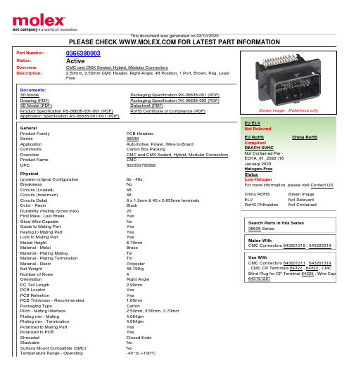
Termination Interface: Style
Electrical Current - Maximum per Contact Voltage - Maximum
Solder Process Data Lead-freeProcess Capability
Material Info
Reference - Drawing Numbers Application Specification Packaging Specification Product Specification Sales Drawing
PCB Headers 36638 Automotive, Power, Wire-to-Board Carton Box Packing CMC and CMX Sealed, Hybrid, Modular Connectors CMC 822350795692
8p - 40s No 48 48 8 x 1.5mm & 40 x 0.635mm terminals Black 20 Yes No Yes Yes Yes 6.70mm Brass Tin Tin Polyester 46.799/g 4 Right Angle 2.90mm Yes Yes 1.60mm Carton 2.50mm, 3.50mm, 3.70mm 4.064µm 4.064µm Yes Yes Closed Ends No No -40° to +100°C
Mates With CMC Connectors 643201319 , 643203319
Use With CMC Connectors 643201311 , 643201319 , CMC CP Terminals 64322 , 64323 , CMC Blind Plug for CP Terminal 64325 , Wire Cap 643191201
辽宁工程技术大学·应用技术学院

辽宁工程技术大学机电设备与管理自考本科论文辽宁工程技术大学机电设备与管理自考本科毕业论文题目:煤矿带式输送机保护控制系统设计准考证号:姓名:指导老师:摘要带式输送机是一种由摩擦驱动引起连续动作的运输机械。
随着煤矿机电一体化水平的不断提高,煤矿井下带式输送机使用越来越广泛,台数越来越多,运距越来越长,在带式输送机的使用过程中经常出现一些打滑、跑偏、堆煤、烟雾、超温等故障,影响煤矿生产和安全。
为了避免这些事故的发生,带式输送机保护器孕育而生。
它不仅可以时时监视皮带的状态,还可以在皮带出现故障时进行报警,且对皮带的状态予以改变,进行保护。
带式输送机保护器的应用,使皮带有了可靠的保护。
本文设计的带式输送机保护控制系统主要用于对带式输送机的保护和控制,具有九大保护功能,其是在现有的八大保护基础上加入粉尘保护,分别为:速度保护、堆煤保护、跑偏保护、烟雾保护、温度保护、沿线紧急停车、撕裂保护、张紧力保护、粉尘保护。
可语言报警及显示故障类型,具有集中控制和单台操作功能。
同时,系统还增加了张紧和跑偏自动调整控制,使潜在的故障自动排除。
本论文结合DSP技术、单片机技术和传感器技术,对带式输送机的保护控制系统进行设计。
其中,传感器负责数据的采集;DsP采用TI公司的TMs320LF2407型芯片,其用于接收传感器送来的信号并送给单片机显示,当信号超限时,发出语音报警,并控制相应的继电器的吸合;单片机采用Af89C51芯片,其用于接收DSP送来的信号,通过液晶显示屏显示故障类型。
根据系统的工作原理,本文对系统的软、硬件进行了设计。
由于带式输送机保护控制系统是一个多传感器系统,本文采用信息融合的方法,根据系统的融合结构模型及Kalman滤波算法和模糊逻辑法,对此多传感器系统的信息进行互补整合,使得到的融合结果对检测环境的描述更准确,从而增加了传感器系统的可信度。
经试验分析,本文设计的带式输送机保护控制系统可以有效地做到保护、控制带式输送机,且通过显示和通一讯使工作人员更好的了解带式输送机的现状和予以控制。
智能型电机保护控制器MCU在水泥厂的应用——沙特NRCC和约旦AMCP水泥厂的应用实践
项 目中的实际应用 , 作一简单介绍 。
简化 了传统意义上 的电动机 回路 的维护 ,降低 了设
备维护成本 。 对 于 电动机及 运行 设备 来说 , 0 一 / 0 一 M11PM12 P 的应用意味着—— 可靠 的保护 ; 大限度 的利用 ; 最 连 续的监测 ; 高度的灵活性。
控制、 面板控制及现场控制 。 本项 目中采用 的是 中控 31 M1 2 P的 连接 和设 定 . 0一 优先控制方式 ,也就是说在中控不允许设备启动及 M12 P支持 Po bs P协议 ,在 D S L 0一 r uD i f C / C系 P 通讯故 障的情况下 ,通过现场按钮和面板按钮是无 统结构 中它作为 Pob s r u 从站 。Pob s P是 一种 i f r uD i f
1 产 品概 述
11 概述 .
MI1PM12 P是 具 有 先 进 的 现 场 总 线 接 口 , O一/ 0一 基于微处理器技术开发研制 的电动机保护与控制装 置 。由微 处理 器来 执行 电动 机 的保 护 与 控 制功 能 , 完
成对 电动机操作次数的统计 明该装置优化 了D S 电机起 动器之 间的连接 , 高 了 备可用性 , 系统的起 动 、 证 C 和 提 设 使 运行和维护 费用大
大 降低 。 关键词 : 电机 保 护 控 制 器 ; I2 P; C 7 Po b s P M O - P S ;rf u i D
中图分类号 : M9 15 T 2.
《 装备制造技术>o 1 > l 年第 8 2 期
主一 从 式 的现 场 总 线协 议 。D SP C系 统 循 环读 取 C /L M1 1PM12 P各 输 人 点 的状 态 ,并且 能够 对 其 执 0一/ 0一 行控 制命 令 。
保隆科技推出全球最小的胎压监测系统模块

保隆科技推出全球最小的胎压监测系统模块中国上海讯–上海保隆汽车科技股份有限公司(保隆科技)宣布推出全球最小的、高度集成的胎压监测系统(TPMS)模块,其重量极轻,仅8克。
保隆TPMS模块可确保轮胎气压处于正常范围,防止出现危险的爆胎和瘪胎情况,从而帮助汽车OEM和后装市场供应商提高汽车的安全性。
保隆TPMS模块采用了飞思卡尔®半导体的FXTH87胎压监测系统,提供超长的电池使用寿命,并保证解决方案的长期有效。
飞思卡尔的FXTH87胎压监测系统也于当天公布,比竞争对手的解决方案小50%,净重仅0.3克。
胎压不合适对于驾驶员来说既危险又不经济。
据美国国家公路交通安全管理局估计,每年发生23,000起因轮胎漏气或爆胎引起的交通事故,其中535起为死亡事故,如果胎压合适,就能避免事故的发生。
正确的胎压不仅能增加安全性、减少伤亡事故,而且还能提高燃油经济性、降低排放,因此许多地区开始制订法规,要求安装该技术。
美国于2005开始要求新车安装TPMS模块。
之后其他许多地区纷纷效仿,欧盟、中国大陆和台湾要求自2014年起新车安装TPMS模块,日本、韩国和俄罗斯于2015开始要求安装。
保隆集团首席执行官张祖秋表示:“我们广泛的产品组合已销往80多个国家和地区,能够采用汽车市场领导者飞思卡尔推出的胎压监测系统,对于两家公司来说是一个双赢的合作。
胎压监测系统模块的需求在迅速增长,因为越来越多的国家希望利用这些在安全和环境等方面具有优势的解决方案。
我们这款最新平台D型模块是基于飞思卡尔技术的第四代TPMS模块解决方案,具有尺寸小、电池寿命长等特点,这款产品考虑了系统空间和功率的限制,是客户的理想之选。
”保隆的D型TPMS模块采用飞思卡尔微型胎压监测系统,代表了最高的汽车质量标准,同时还能加快上市时间,简化设计,降低成本,提高易用性。
小尺寸、低功耗的飞思卡尔FXTH87 系统允许设计人员创建更小、更轻的模块,而且电池寿命更长,能支持不断扩展的功能集。
美国宝克公司检测线原理与维修(四轮定位仪、灯光检测仪、转毂试验台)

美国宝克公司检测线原理、使用和维修(四轮定位仪、灯光检测仪、转毂试验台)维修技术培训资料陈刚(笔名:陈云龙)2006-5/2008-2目录本课程申报48课时。
以专题式进行讲解,计划讲解如下专题:第一部分:四轮定位仪第一节:四轮定位仪的工艺任务及工作流程(专题1)第二节:四轮定位仪的构成(专题2)第三节:四轮定位仪测试原理分析(专题3)第四节:新车型激光头重新定位方法(专题4)第五节:激光系统初始化和标定——开发区设备(专题5)第六节:激光系统初始化和标定——红旗事业部设备(专题6)第七节:方向盘基准仪校准(专题7)第八节:设备常规操作方法及显示(专题8)第九节:车型的修改和设置(专题9)第十节:激光系统和成像分析(专题10)第十一节:四轮定位仪车辆连续跑偏质量问题的分析(专题11)第十二节:四轮定位的工艺参数修改(专题12)第十三节:工艺参数分析(专题13)第十四节:VME总线板卡概述——红旗事业部设备(专题14)第十五节:检测线DOS系统(专题15)第二部分:灯光测试仪第一节:灯光测试仪的任务第二节:灯光测试仪的构成第三节:灯光测试仪的测试原理第四节:照相机调整第五节:光轴偏转校准——开发区设备第六节:光轴偏转校准——红旗事业部设备第七节:灯箱方向性标定第八节:光强度标定——开发区设备第九节:光强度标定——红旗事业部设备第十节:增加车型。
第十一节:参数系统分析第十二节:使用和维护相关补充说明第三部分:转毂试验台第一节:转毂试验台的工艺任务及工作流程第二节:转毂试验台的构成第三节:转毂试验台的测试原理第四节:设备操作方法第五节:阻滞力标定第六节:手刹、脚刹车标定第七节:轮距修改第八节:声级标定第九节:人机接口界面第十节:参数系统分析第十一节:使用和维护相关提示前言我们公司的整车检测线是从美国宝克公司定货的设备。
直属总装车间包括两条线及隔音间、通风系统、网络系统等。
每条线包括四轮定位仪、转毂试验台、大灯测试仪、侧滑试验台四台主体设备。
PCS-221N-G-H2_X_说明书_国内中文_国内标准版_X_R1.01_(ZL_ZNKZ3042.1308)
ii
பைடு நூலகம்
南京南瑞继保电气有限公司
目录
PCS-221N-G-H2 常规母线电压合并单元
前言.................................................................................................................................................... i 目录.................................................................................................................................................. iii 第 1 章 概述...................................................................................................................................... 1
版权声明
版本: R1.01 P/N: ZL_ZNKZ3042.1308
Copyright © 2013 NR 南京南瑞继保电气有限公司版权所有
我们对本文档及其中的内容具有全部的知识产权。除非特别授权,禁 止复制或向第三方分发。凡侵犯本公司版权等知识产权的,本公司必 依法追究其法律责任。
购买产品,请联系: 电话:025-87178911,传真: 025-52100511、025-52100512 电子信箱:market@
1.1 应用 .................................................................................................................................... 1 1.2 功能 .................................................................................................................................... 1 1.3 特点 .................................................................................................................................... 1 1.4 订货选型 ............................................................................................................................. 2 1.5 产品执行标准...................................................................................................................... 2 第 2 章 技术参数 .............................................................................................................................. 3 2.1 电气参数 ............................................................................................................................. 3 2.2 环境条件参数...................................................................................................................... 4 2.3 通讯接口 ............................................................................................................................. 4 2.4 型式试验 ............................................................................................................................. 5 2.5 合并单元功能参数 .............................................................................................................. 6 2.6 认证 .................................................................................................................................... 6 第 3 章 工作原理 .............................................................................................................................. 9 3.1 PCS-221N-G-H2 配置连接.................................................................................................. 9 3.2 电压并列原理...................................................................................................................... 9 3.3 双重化采样 ....................................................................................................................... 15 3.4 数据帧............................................................................................................................... 16 第 4 章 硬件及结构安装 ................................................................................................................. 17 4.1 概述 .................................................................................................................................. 17 4.2 结构与安装 ....................................................................................................................... 18 4.3 电气安装和接线 ................................................................................................................ 20 4.4 机箱 .................................................................................................................................. 22 4.5 主 DSP 模块(NR1136E/F) ........................................................................................... 22 4.6 采样 DPS 模块(NR1157C)........................................................................................... 23 4.7 交流输入模块(NR1401-12U-C) ................................................................................... 23
霍尼韦尔 HMR2300 智能数字磁场计 使用手册说明书

单位Volts mA ˚C ˚C Gauss %FS %FS %FS %FS %FS %FS µ Gauss ppm/˚C ppm/V mm g force Gauss grams应用●航空用和船用罗盘● 车辆遥感检测(侧滚/俯仰/偏航)● 过程控制● 实验室仪器● 异常检测● 交通车辆检测● 保安系统特性●带微处理器的智能传感器● 低成本,使用方便—一插即用● 量程:± 2Gauss 分辨率67 µ Gauss ● 采样速度可选:10—157采样点/秒● 三轴数字量输出;BCD 码或二进制码,ASCII 码● 9600或19200波特率可选择● 符合RS-485标准,总线上连接多个单元● 符合RS-232标准进行单点读数概述:霍尼韦尔公司生产的三轴智能数字磁场计(HMR )可检测磁场的强度和方向,并与计算机直接通讯,输出X 、Y 、Z 三个轴的分量,用三个独立的桥路定向检测磁场的X ,Y ,Z 轴的分量。
电桥输出端相应电压的变化通过一个16位AD 转换为数字量。
可输入命令组态数据采样速率,输出格式、平均读数和零点偏移(见表1)。
电路板上的EEPROM 存储了任意一项组态变化以便下一通电作准备。
其它输入命令包括波特率设置、装置的ID 号码设置和系列号码设置,及选择50KHz 或60KHz 的数字滤波器来抵消环境磁场干扰。
在玻莫合金电桥上使用了一种独特的开关技术以消除过去磁场的影响,这种技术可以消除桥路偏置和其他电子设备引起的偏置。
当微处理器接收到相应的选通ID 信号后,输出X ,Y ,Z 的串行码。
数据以9600或19,200的波特率按RS-485或RS-232标准输入PC 机中。
RS-485标准允许在一对线上挂接32台装置,连线长度可达4000英尺。
HMR 的地址可储存在EEPROM 中(32个独立)进行在线识别和读数。
内置的微处理器磁检测、数字滤波和所有输出通讯,免除外部调节的电路。
F200说明书
安装指南
型号:F200
neidnl [选取日期]
炥莱茵科技有限公司
目录
炥莱茵科技有限公司
一、产品概述及功能简介 ......................................................................................................................2 二、技术指标.........................................................................................................................................3 三﹑包装清单.........................................................................................................................................3
Bacharach IAM-100 集成区域监测仪及可选16通道控制器操作手册说明书

Integrated Area Monitor and Optional 16-Channel ControllerInstallation and Operation ManualInstruction 6209-9000Rev 2 – January 2016IAM-100 and Controller ManualWARRANTY POLICYBACHARACH, INC. WARRANTS THIS INSTRUMENT, EXCLUDING SENSORS, TO BE FREE FROM DEFECTS IN MATERIALS AND WORKMANSHIP FOR A PERIOD OF ONE YEAR FROM THE DATE OF PURCHASE BY THE ORIGINAL OWNER. THE SENSORS HAVE A WARRANTY PERIOD OF ONE YEAR FROM THE DATE OF PURCHASE. IF THE PRODUCT SHOULD BECOME DEFECTIVE WITHIN THIS WARRANTY PERIOD, WE WILL REPAIR OR REPLACE IT AT OUR DISCRETION.THE WARRANTY STATUS MAY BE AFFECTED IF THE INSTRUMENT HAS NOT BEEN USED AND MAINTAINED PER THE INSTRUCTIONS IN THIS MANUAL OR HAS BEEN ABUSED, DAMAGED, OR MODIFIED IN ANY WAY. THIS INSTRUMENT IS ONLY TO BE USED FOR PURPOSES STATED HEREIN. THE MANUFACTURER IS NOT LIABLE FOR AUXILIARY INTERFACED EQUIPMENT OR CONSEQUENTIAL DAMAGE.DUE TO ONGOING RESEARCH, DEVELOPMENT, AND PRODUCT TESTING, THE MANUFACTURER RESERVES THE RIGHT TO CHANGE SPECIFICATIONS WITHOUT NOTICE. THE INFORMATION CONTAINED HEREIN IS BASED ON DATA CONSIDERED ACCURATE. HOWEVER, NO WARRANTY IS EXPRESSED OR IMPLIED REGARDING THE ACCURACY OF THIS DATA.ALL GOODS MUST BE SHIPPED TO THE MANUFACTURER BY PREPAID FREIGHT. ALL RETURNED GOODS MUST BE PRE-AUTHORIZED BY OBTAINING A RETURN MERCHANDISE AUTHORIZATION (RMA) NUMBER. CONTACT THE MANUFACTURER FOR A NUMBER AND PROCEDURES REQUIRED FOR PRODUCT TRANSPORT.SERVICE POLICYBACHARACH, INC. MAINTAINS AN INSTRUMENT SERVICE FACILITY AT THE FACTORY. SOME BACHARACH DISTRIBUTORS / AGENTS MAY ALSO HAVE REPAIR FACILITIES, HOWEVER, BACHARACH ASSUMES NO LIABILITY FOR SERVICE PERFORMED BY ANYONE OTHER THAN BACHARACH PERSONNEL. REPAIRS ARE WARRANTED FOR 90 DAYS AFTER DATE OF SHIPMENT (SENSORS, PUMPS, FILTERS AND BATTERIES HAVE INDIVIDUAL WARRANTIES). SHOULD YOUR INSTRUMENT REQUIRE NON-WARRANTY REPAIR, YOU MAY CONTACT THE DISTRIBUTOR FROM WHOM IT WAS PURCHASED OR YOU MAY CONTACT BACHARACH DIRECTLY.IF BACHARACH IS TO DO THE REPAIR WORK, SEND THE INSTRUMENT, PREPAID, TO BACHARACH, INC. AT THE FOLLOWING ADDRESS.IAM-100 and Controller ManualALWAYS INCLUDE YOUR RMA #, ADDRESS, TELEPHONE NUMBER, CONTACT NAME, SHIPPING/BILLING INFORMATION AND A DESCRIPTION OF THE DEFECT AS YOU PERCEIVE IT. YOU WILL BE CONTACTED WITH A COST ESTIMATE FOR EXPECTED REPAIRS PRIOR TO THE PERFORMANCE OF ANY SERVICE WORK. FOR LIABILITY REASONS, BACHARACH HAS A POLICY OF PERFORMING ALL NEEDED REPAIRS TO RESTORE THE INSTRUMENT TO FULL OPERATING CONDITION.PRIOR TO SHIPPING EQUIPMENT TO BACHARACH, CONTACT OUR OFFICE FOR AN RMA # (RETURN MERCHANDISE AUTHORIZATION). ALL RETURNED GOODS MUST BE ACCOMPANIED WITH AN RMA NUMBER.PACK THE EQUIPMENT WELL (IN ITS ORIGINAL PACKING IF POSSIBLE), AS BACHARACH CANNOT BE HELD RESPONSIBLE FOR ANY DAMAGE INCURRED DURING SHIPPING TO OUR FACILITY. FAILURE TO INCLUDE A VALID RMA NUMBER WILL RESULT IN LONGER PROCESSING TIME AND MAY ADD EXTRA COST.NOTICESCOPYRIGHTS: THIS MANUAL IS SUBJECT TO COPYRIGHT PROTECTION; ALL RIGHTS ARE RESERVED UNDER INTERNATIONAL AND DOMESTIC COPYRIGHT LAWS. THIS MANUAL MAY NOT BE COPIED OR TRANSLATED, IN WHOLE OR IN PART, IN ANY MANNER OR FORMAT, WITHOUT THE WRITTEN PERMISSION OF BACHARACH, INC.ALL SOFTWARE WHICH BACHARACH UTILIZES AND/OR DISTRIBUTES, HOLDS A PROPRIETARY INTEREST AND IS ALSO SUBJECT TO COPYRIGHT PROTECTION AND ALL RIGHTS ARE RESERVED. NO PARTY MAY USE OR COPY SUCH SOFTWARE IN ANY MANNER OR FORMAT, EXCEPT TO THE EXTENT THAT BACHARACH GRANTS THEM A LICENSE TO DO SO. IF THIS SOFTWARE IS BEING LOADED ONTO MORE THAN ONE COMPUTER, EXTRA SOFTWARE LICENSES MUST BE PURCHASED.TECHNICIAN USE ONLYTHIS UNIT MUST BE INSTALLED BY A SUITABLY QUALIFIED TECHNICIAN WHO WILL INSTALL THIS UNIT IN ACCORDANCE WITH THESE INSTRUCTIONS AND THE STANDARDS IN THEIR PARTICULAR INDUSTRY/COUNTRY. SUITABLY QUALIFIED OPERATORS OF THE UNIT SHOULD BE AWARE OF THE REGULATIONS AND STANDARDS IN THEIR INDUSTRY/COUNTRY FOR THE OPERATION OF THIS UNIT. THESE NOTES ARE ONLY INTENDED AS A GUIDE AND THE MANUFACTURER BEARS NO RESPONSIBILITY FOR THE INSTALLATION OR OPERATION OF THIS UNIT.FAILURE TO INSTALL AND OPERATE THE UNIT IN ACCORDANCE WITH THESE INSTRUCTIONS AND WITH INDUSTRY GUIDELINES MAY CAUSE SERIOUS INJURY INCLUDING DEATH AND THE MANUFACTURER WILL NOT BE HELD RESPONSIBLE IN THIS REGARD.IAM-100 and Controller ManualTable of ContentsSECTION 1.OVERVIEW (5)1.1. Introduction (5)1.2. Applications (5)1.3. Specifications (8)SECTION 2.PLACING SENSORS (10)2.1. General Guidelines (10)2.2. Air Conditioning (Direct Systems VRF/VRV) (11)SECTION 3.HOUSING DIMENSIONS (12)SECTION 4.WIRING INSTRUCTIONS (15)4.1. Wiring the IAM-100 (15)4.2. Wiring the IAM-100 Controller (17)4.3. Remote Sensor Head Installation (19)SECTION 5.OPERATING INSTRUCTIONS (22)5.1. IAM-100 (22)5.2. IAM Controller (23)SECTION 6.FUNCTIONAL TESTS AND CALIBRATION (25)6.1. Overview (25)6.2. Bump Testing (27)6.3. Checking and Setting the Zero Setting (29)6.4. IAM Controller (30)SECTION 7.TROUBLESHOOTING (31)CE DECLARATION OF CONFORMITY (32)IAM-100 and Controller Manual Section 1. Overview1.1. IntroductionThe IAM-100 is a system that combines sensor and monitoring features in an integrated unit. It is a stand-alone system used to detect gases in an area, room, zone, airspace or airflow.The IAM-100 can be expanded into large gas detection systems using the optional IAM controller.Up to 16 IAM-100s can connect to an IAM controller. The controller shows any sensor in alarm and has relays for control purposes. These controllers can be connected to each other enabling the construction of large gas detector systems.1.2. ApplicationsThe IAM-100 is an ideal solution for gas detection in the following occupied spaces:•hotel rooms •storage facilities•conference rooms •theaters•apartment blocks •airports•office buildings •light industrial spaces•air conditioned spaces •large systems requiring many sensors. Typical applications include the following.IAM-100 and Controller ManualFigure 1. IAM-100Figure 2. Optional IAM-100 ControllerIAM-100 and Controller ManualFigure 3. Sample Architecture DiagramIAM-100 and Controller Manual 1.3. SpecificationsIAM-100 and Controller ManualIAM-100 and Controller ManualSection 2. Placing Sensors2.1. General GuidelinesNOTE: This instrument is equipped with a semiconductor sensor for the detection of refrigerant gases. Semiconductor sensors are not gas specific and respond to a variety of other gases including propane exhaust, cleaners, and solvents. Changes in temperature and humidity may also affect the sensor’s performance.The IAM-100 and optional controller (where applicable) should be positioned carefully to avoid mechanical damage (from moving machinery, doors, etc.) and thermal extremes (close to heaters). Units should not be placed unprotected in direct or strong drafts/airflows and areas where water, moisture, or steam is present.Avoid routing sensor cabling outside of premises, or between buildings via overhead cables. Also, sensor wiring should be kept a minimum of 500 mm [20 inches] from the main power supply and telephone cables.When connecting the main power supply and/or sensor cables ensure a second strain relief is used. As a strain relief, use a cable tie inside the enclosure within 25mm [1 inch] of the cable termination.NOTE: The IAM-100 and optional controllers must be located within the appropriate wire lengths from the central control unit (if used).In all cases the sensor supplied is designed for maximum sensitivity to a particular gas. However, in certain circumstances false alarms may be caused by the occasional presence of sufficiently high concentrations of other gaseous impurities. Examples of situations where such abnormalities may arise include the following:• Room maintenance activity involving solvent or fumes or refrigerant leaks.•Heavy localized exhaust fumes (carbon monoxide, dioxide, andpropane).An optional response delay may be activated to minimize the possibilities of false alarms.2.2. Air Conditioning (Direct Systems VRF/VRV)To ensure compliance with EN378 at least one detector should be installed in each occupied space being considered. In this case refrigerants are heavier than air and detectors should have their sensors mounted low, e.g., at less than bed height in the case of a hotel or other similar Category Class A space. Ceiling voids or other voids if not sealed are part of the occupied space.CAUTION:Monitoring ceiling voids in a hotel room would not strictly comply with EN378.IMPORTANT: Carefully consider ramifications of using too few sensors. A few extra sensors could make a significant difference if a gas leak occurs.Section 3. Housing DimensionsFigure 4. Dimensions of the IAM-100 Housing (Front)Figure 5. Typical Dimensions of the IAM-100 (Back)Figure 6. Controller HousingSection 4. Wiring Instructions4.1. Wiring the IAM-100Open the IAM-100 by removing the two front cover screws. Remove the metal faceplate and locate the connection terminals.Figure 7. IAM-100 Internal ComponentsNOTE: The maximum wire size into terminal blocks is 1.5 mm2 [16 AWG].NOTE: Review and agree upon end-user requirements before setting buzzer enable/disable, the relay/buzzer delay and manual vs. automatic reset (latching).NOTE: Connection to main power supply must be done in accordance with local wiring regulations, and should not be longer than 3 meters from the controller. It is recommended to connect to main power through approved, switchable, fused (3A fuse recommended) and easily accessible electrical spur. This should be a part of building installation and be marked as disconnect for the unit.•The main power cable used should be compliant with local regulations.•If replacement of the main fuse is required, use a suitable replacement.4.2. Wiring the IAM-100 ControllerOpen the IAM-C by removing the two front cover screws. Remove the metal faceplate and locate the connection terminals. To install the IAM-C, refer to the network drawing (Figure 3) and wiring diagram (Figure 8).Figure 8. Controller Internal ComponentsNOTE: The maximum wire size into terminal blocks is 1.5 mm2[16 AWG].NOTE: Review and agree upon end-user requirements before setting buzzer enable/disable, the relay/buzzer delay andmanual vs. automatic reset (latching).NOTE: Connection to main power supply must be via an approved, readily accessible, switched spur and fused (3 Amp fuse) or as per local wiring regulations which should be within 3 meters (10 feet) of the controller. It should be part of the building installation and be marked as the disconnect for the device. • The main power cable used should be compliant with local regulations.•If replacement of the main fuse is required, use a suitable replacement.4.3. Remote Sensor InstallationIf you do not wish to surface mount the IAM or need to match room decor, Bacharach can supply a remote sensor and a decorative faceplate (standard finish is a unit with brushed stainless steel). The remote sensor is mounted in an electrical back box 44 mm [1.73 inches] deep to which the faceplate is fitted.IMPORTANT: Cleaning the decorative faceplate should be limited to light dusting. It should not be sprayed with cleaning/polishing aerosols.NOTE: For remote sensor configurations, the sensor element is mounted on a small remote sensor PCBthatconnects to the IAM-100’s main PCB via a 4-wire cable.Figure 9. Local vs. Remote SensorSection 5. Operating Instructions 5.1. IAM-1005.2. IAM ControllerFigure 11. External Components of the ControllerNOTE: If all of the red LEDs are blinking approximately every 5 seconds on a master panel, then remove the link on Jumper position JP3 as this should be in the disabled position on a master panel (factory default setting is disabled).Access Screws (2 Places)Section 6. Functional Tests and Calibration6.1. OverviewNOTE: The IAM-100 is calibrated at the factory. After installation, a zero adjustment maybe required due to differences in environmental conditions.IMPORTANT: If the IAM-100 is exposed to a large leak it should be tested to ensure correct functionality, and the sensor replaced if necessary.To comply with the requirements of EN378 and the European F-GAS regulation, sensors must be tested annually. However, local regulations may specify the nature and frequency of this test. After sensor element replacement, recalibration of the unit using known concentration of gas is required.CAUTION: Check local regulations on calibration or testing requirements.IMPORTANT: The testing and/or calibration of the unit must be carried out by a suitably qualified technician, and must be done:• in accordance with this manual•in compliance with locally applicable guidelines and regulations.Suitably qualified operators of the unit should be aware of the regulations and standards set down by the industry/country for the testing or calibration of this unit. This manual is only intended as a guide and, insofar as permitted by law, the manufacturer accepts no responsibility for the calibration, testing, or operation of this unit.The frequency and nature of testing or calibration may be determined by local regulation or standards.EN378 and the F-GAS Regulation require an annual check in accordance with the manufacturer’s recommendation.IMPORTANT: Failure to test or calibrate the unit in accordance with applicable instructions and with industry guidelines may result in serious injury or death. The manufacturer is not liable for any loss, injury, or damage arising from improper testing, incorrect calibration, or inappropriate use of the unit.IMPORTANT: Calibration should be done at least once per year.IMPORTANT: In applications where life safety is critical, calibration should be done quarterly (every 3 months) or on a more frequent basis. Bacharach is not responsible for setting safety practices and policies. Safe work procedures including calibration policies are best determined by company policy, industry standards, and local codes.There are two concepts that need to be differentiated:Bump Test Exposing the sensor to a known concentration of targetgas and observing its response to the gas. The objective is to establish if the sensor is reacting to the gas and all the sensor outputs are working correctly. There are two types of bump test. • Quantified: A known concentration of gas isused.• Non-Quantified: A gas of unknown concentration isused.Calibration Exposing the sensor to a calibration gas, setting the“Standby voltage”, the span/range, and checking/ adjusting all the outputs, to ensure that they are activated at the specified gas concentration.NOTE: For improved accuracy and response, the instrument should be zeroed and calibrated in the environment in which it is being installed.CAUTION: Before performing the bump test:•Advise occupants, plant operators, and supervisors.•Check if the IAM-100 is connected to external systems then disconnect as instructed by the customer.•Deactivate the alarm delay (if active) by removing the alarm delay jumpers per Figure 7.•To ensure higher accuracy, the IAM-100 should be powered up for at least 24 hours before anytests/calibration or adjustment are made.6.2. Bump TestingAfter installation, it is recommended to perform a bump test to ensure proper functionality of the unit. Expose the sensors to test gas, preferably target gas.The bump test should put the system into alarm. The red LED will light showing the system is in alarm. The delay will prevent the buzzer from sounding and the relay from switching (if the delay is set).To test the buzzer and/or relay function, check the delay is set at zero using the multi-pin connector positions 1 and 2 (as shown in Figure 7) and expose to gas as above. You can mute the buzzer using the mute button.After the gas has cleared and the red LED has switched off you can reset the alarm relay and buzzer by using the reset button (if manual reset has been selected).Before testing the sensors on site the IAM-100 must have been powered up and allowed to stabilize for several hours, preferably over a period of 24 hours.When testing the sensors, also ensure that the IAM Controller functions correctly (if installed) per section 6.4.NOTE: Ideally bump tests are to be conducted at installationsite in a clean air atmosphere.IMPORTANT: After a semiconductor sensor is exposed to asubstantial gas leak, the sensor should be checked andreplaced if necessary. After sensor element replacement,recalibration of the unit using a known concentration of gas isrequired.NOTE: Do not pressurize the sensor.NOTE: You MUST use calibration gas in a balance of air (not N2).NOTE: Prior to carrying out a bump test, check and adjust the zero setting. Refer to Section 6.3.Figure 12. Gas Cylinder and Test Hardware6.3. Checking and Setting the Zero SettingChecking and setting the zero setting may be required upon initial installation. Ensure the unit was powered up for at least 24 hours before making any adjustmentTools Required:• A voltmeter (crocodile clips are recommended)•Factory standby (zero) voltage from side label•ScrewdriverFigure 13. Checking and Setting the Zero Setting 6.4. IAM ControllerIf your installation has an IAM Controller, ensure that the controller’sfunctions are activating accordingly when testing the sensors.Section 7. TroubleshootingD ECLARATION OF C ONFORMITYThe undersigned hereby declares that the above referenced products are in conformity with the provisions of the following standard(s) and is in accordance with the following directive(s). Directive(s):Standard(s):Signature: Name: Aaron Kennison Title: Engineering Manager Date: 1/3/2013The technical documentation file required by this directive is maintained at the corporate headquarters of Bacharach, Inc.D ECLARATION OF C ONFORMITYThe undersigned hereby declares that the above referenced products are in conformity with the provisions of the following standard(s) and is in accordance with the following directive(s).Directive(s):Standard(s):Signature:Name:Aaron KennisonTitle:Engineering ManagerDate: 03/25/2013The technical documentation file required by this directive is maintained at the corporateheadquarters of Bacharach, Inc.World Headquarters621 Hunt Valley Circle, New Kensington, Pennsylvania 15068 Phone: 724-334-5000 • Toll Free: 1-800-736-4666 • Fax: 724-334-5001 Website: • E-mail:********************。
力信RMS-C煤机自动导向系统技术协议(1)
技术协议力信R M S-C煤机导向系统一、产品名称力信RMS-C煤机导向系统二、设计及产品规范2.1.CECS81:96 《工业计算机监控系统抗干扰技术规范》2.2.GB/T8566-95 《信息技术软件生存期过程》2.3.GB8566 《计算机软件开发规范》2.4.GB/T12504 《计算机软件质量保证计划规范》2.5.GBJ63-90 《电力装置的电测量仪表装置设计规范》2.6.GB4208-2008 《外壳防护等级(IP)代码》2.7.GB7450-87 《电子设备雷击保护条例》2.8.IEC1000-1995 《电磁兼容性》2.9.IEEE-472 《浪涌保护规格》2.10.GB3836.1-2010 《爆炸性环境第1部分:设备通用要求》2.11.GB3836.2-2010 《爆炸性环境第2部分:由隔爆外壳“d”保护的设备》2.12.GB3836.4-2010 《爆炸性环境第4部分:由本质安全型“i”保护的设备》2.13.MT209-1990 《煤矿通信、检测、控制用电工产品通用技术条件》2.14.MT818 《煤矿用电缆》2.15.JB4002-1992 《矿用隔爆型低压电器用接线端子》2.16.AQ1043-2007 《矿用产品安全标志标识》三、系统工作原理力信RMS-C煤机导向系统为煤矿巷道掘进机、连采机掘锚一体机等大型隧道设备提供实时姿态的导航产品。
该系统采用惯性导航方式,为掘锚一体机前进过程提供精确姿态数据和位置数据。
陀螺仪提供航向角、滚动角、俯仰角以及三轴加速度值,通过导航算法及其他误差剔除算法实时提供载体的航向指导。
力信RMS-C煤机导向系统连接图四、系统工作范围4.1 环境温度:-10℃~+60℃;4.2 相对湿度:>85%;4.3 平均海拔:地表下500m;4.4 适用范围:在有甲烷混合气体和煤尘,且有爆炸危险的矿井中工作、强振动、高冲击;4.5 空气流通速度:0.5~6m/s;4.6 工作日制:24小时;4.7 环境适应性:含瓦斯气体、低浓度灰尘、潮湿、振动、弱光等恶劣环境;2/ 44.8 设备振动:轴向±10倍重力加速度、径向±10倍重力加速度;4.9 防护等级:IP67五、配置清单六、系统软件模块及功能6.1.设备供电:矿用隔爆兼本安型计算机与矿用隔爆兼本安型直流稳压电源采用交流AC127V矿用照明电源供电;矿用隔爆型陀螺仪由矿用隔爆兼本安型直流稳压电源DC 18V供电;6.2.线形计算:根据隧道设计轴线线型要素自动计算隧道轴线坐标序列,无需人工计算和手动输入,并且多方检核导入显示数据;6.3.参数显示:实时显示掘锚一体机行走距离,行驶趋向,航向,设计航向,俯仰角,侧装角姿态;6.4.系统状态:实时显示陀螺仪连接状态;6.5.系统预警:实时自动检核硬件连接状态报警,姿态超限报警,运行故障报警;6.6.系统操作:具有开始导向,系统设置,工程设置,数据查询等功能操作;6.7.数据查询:具有推进导向历史数据全参数查询,完成的系统运行日志及操作日志查询;七、系统技术参数力信RMS-C煤机导向系统主要技术参数如下表:4/ 4。
- 1、下载文档前请自行甄别文档内容的完整性,平台不提供额外的编辑、内容补充、找答案等附加服务。
- 2、"仅部分预览"的文档,不可在线预览部分如存在完整性等问题,可反馈申请退款(可完整预览的文档不适用该条件!)。
- 3、如文档侵犯您的权益,请联系客服反馈,我们会尽快为您处理(人工客服工作时间:9:00-18:30)。
开关电路 传感元件
输出电路
N-极检测输出 S-极检测输出
地标磁体 (N-极在上面/SMG-100N)(S-极在上面/SMG-100S)
内部构造图
2. 规格
项目 供给电压 耗费电流 运行温度 运行湿度 保存温度 保存湿度 保护构造 运行空隙 使用磁体
灵敏度
内容 直流+10 V 〜 +30V 之间, 纹波 (p-p) 2% 以下 15mA 以下 -10 和 +60℃之间 35% 和 95%之间 相对湿度(不许凝结、冻结) -20 和 +70℃之间 35% 和 95% 之间相对湿度(不许凝结、冻结) IP-54 (国际电工委员会规格) 从 15 到 40mm (使用 SMG-100N , SMG-100S 时.) ※1 SMG-100N (N-极在上面) SMG-100S (S-极在上面) N-极检测; 0.5mT±0.1mT 或以上 (N-极)※2
4. 安装
SMR-100C 必 须 安 装 在 离 马 达 等 磁 性 发 电 机 较 远 的 地 方 。 磁 性 物 体 附 近 也 许 发 生 SMR-100 C 的 错 误 运 行 。 如 果 SMR-1 00C 需 要 安 装 在 磁 性 物 体 的 附 近 , , 请一定设定空间如下:
磁性物体
MACOME
5. 外形尺寸
检测位置
11.5
检测面 外壳材质:聚酯类
21
标签材质:聚碳酸酯
N-极检测 LED S-极检测 LED
聚氨酯树脂侧
22.5
32
7. 5
15 55
2-4.5×9.5 安装孔
15 25 35
5
φ8
8
(其他尺寸公差 ±0.5)
60±5
输入/输出电缆 2
φ5 耐油、耐寒(绝缘体、护皮、耐热聚氯乙烯)0.3mm
3. 接线
开关电路
Vz=33V
导线颜色/信号
6.5Ω 以下 棕色/直流+10~30V
自复保险丝
直流+30V 以下
Vz=33V
6.5Ω 以下
自复保险丝
白色/S-极检测输出
负荷
+ 直流+10~30V
Vz=33V
6.5Ω 以下
自复保险丝
黑色/N-极检测输出
负荷
蓝色/0V
3/ 7
产品咨询: 新磁(上海)电子有限公司 021-31608531,1560 1837 360 QQ 1436755683 微信 1436755683 上海浦 东新区张江高新技术产业开发区上丰路/977 号/1 幢 B 座
*规格如有变更,恕不另行通知*
MACOME
図番 作成日
SMR-100C-04D-CN0 2012 年 6 月 14 日
承認
作成
7/ 7
产品咨询: 新磁(上海)电子有限公司 021-31608531,1560 1837 360 QQ 1436755683 微信 1436755683 上海 浦东新区张江高新技术产业开发区上丰路/977 号/1 幢 B 座
使用其它的磁体时;
1. 运行空隙必须是最大运行范围的 70%以内。 2. 较强磁场地区会存在磁体的中间。 极和NS 极检测开关运行超过 8mT.的较强磁场。 3. 磁体的两端会存在逆磁场。
使用其他磁体时,请一定安排适当的运行空隙。
2/ 7
产品咨询: 新磁(上海)电子有限公司 021-31608531,1560 1837 360 QQ 1436755683 微信 1436755683 上海浦 东新区张江高新技术产业开发区上丰路/977 号/1 幢 B 座
制造者不负责本产品导致的损失。
8. 服务范围
6/ 7
产品咨询: 新磁(上海)电子有限公司 021-31608531,1560 1837 360 QQ 1436755683 微信 1436755683 上海浦 东新区张江高新技术产业开发区上丰路/977 号/1 幢 B 座
产品价格不含下述费用。该费用另行收费。 (1) 安装产品时的调整、指导以及现场参加等费用。 (2) 产品的维修保养,以及修理。 (3) 技术指导或技术教育。
(残留电压 1V 以下.) 1ms 以下. φ5 耐寒/耐油电缆 0.3mm2 棕色; 直流+10 到+30V 蓝色; 0V 黑色; N-极 输出 白色; S-极 输出
※1. 磁场是 8mT.或以上时,SMR-100C 也检测 逆磁场。
※2. 该数值是在我公司内设备测量的。
运行空隙
跟 SMR-100N 或 S 适当的运行区域是 15~40mm.
MACOME
输出时间表
地标磁体
SMG-100N 或 SMG-100S
输出晶体管
使用 SMG-100N (N-极检测) 使用 SMG-100S (S-极检测)
存在 不存在
ON OFF
输出电压
高
使用 SMG-100N (黑色 - 蓝色)
使用 SMG-100S (白色 - 蓝色)
低
ON
运行显示 LED
OFF
40mm 以上
S.OUT
N.OUT
MACOME CORP.
N.O.
WHITE:S.OUT
N.O.
BROWN:DC+10~30V
BLUE:0V BLACK:N.OUT
SPOT MARK READER
SMR-100C
40mm 以上
磁性物体
30mm以上
40mm 以上
40mm 以上
4/ 7
产品咨询: 新磁(上海)电子有限公司 021-31608531,1560 1837 360 QQ 1436755683 微信 1436755683 上海 浦东新区张江高新技术产业开发区上丰路/977 号/1 幢 B 座
MACOME
1. 概要
SMR-100C 地标传感器 AGV 磁导航传感器 产品说明书
SMR-100C 是 设 计 于 读 出 装 在 磁 式 导 航 AGV 的 停 止 点 或 分 岔 口 的 地 标 磁 体 。 以 积 累 各 个 地 标 磁 体 , AGV 在 道 路 上 认 识 该 所 在 地 . SMR-1 00C 同 时 检 测 SMG-100N (N -极 在 上 面 . /黄 色 夹 层 ) 产 生 N-极 输 出 , 和 SMG-100S (S-极 在 上 面 /绿 色 夹 层 ) 产 生 S-极 输 出 .
产品咨询: 新磁(上海)电子有限公司 021-31608531,1560 1837 360 QQ 1436755683 微信 1436755683 上海浦东新区张江高新技术产业开发区上丰路/977 号/1 幢 B 座
MACOME
SMR-100C
逆磁场地区
S.OUT
N.OUT
MACOME CORP.
BROWN:DC+10~30V
BLUE:0V
BLACK:N.OUT
N.O.
WHITE:S.OUT
N.O.
SPOT MARK READER
SMR-100 C
70%
推荐 运行地区
100% 最大运行范围
较强磁场地区
逆磁场地区 磁体
(对 8mT 以上的 S-极也有输出作用.) S-极检测; 0.5mT±0.1mT 或以上 (S-极)
(对 8mT 以上的 N-极也有输出作用.)
1/ 7
产品咨询: 新磁(上海)电子有限公司 021-31608531,1560 1837 360 QQ 1436755683 微信 1436755683 上海浦 东新区张江高新技术产业开发区上丰路/977 号/1 幢 B 座
产品咨询: 新磁(上海)电子有限公司 021-31608531,1560 1837 360 QQ 1436755683 微信 1436755683 上海 浦东新区张江高新技术产业开发区上丰路/977 号/1 幢 B 座
MACOME
6. 注意点
・ 请一定把输出电缆和动力线分开配线. ・ 对输出电缆的强力拉伸或反复弯曲也许引起断线。 ・ 由于保护构造并不是耐水分,请避免溅上水分. ・ 由于外壳或电缆接触化学药剂(丙酮, 冲淡剂等)后会变形,请避免溅上它们。
MACOME
磁滞 稳定度
供给电压
0.2mT 以下 (+25℃时, 直流+18V) ※2 ±0.1mT 以下 (+10V 和 +30V 之间起伏)
温度
输出
电路
容量
响应时间 输入/ 输出电缆
配线颜色
±0.15mT 以下 ( -10℃ 和 +60℃之间起伏) NPN 集电极开路(常开电路) 直流 30V 以下 吸收电流 100mA 以下
反复弯曲
药品、溶剂、水分等
强力拉伸
马达等 磁体
7.保证
本产品的保证原则是,制造者收到故障产品后,检查其原因。如果故障原因是制造者的理由, 制造者负责替换或修理。保证期间是发货后一年。 但是,如果符合其次情况,则不属于保证的对象范围:
(1) 因用户不适操作、使用的情况下。 (2) 受到外围设备的异常影响时。 (3) 制造者以外的改造或修理的原因。 (4) 不可抗力。
导线颜色和信号
导线颜色
棕色
蓝色
黑色
1
0
白色
0
信号 直流+10~30V
0V N-极检测输出 S-极检测输出
批号
1000+100
100 批号
977A
50 1
夹 层 橡胶磁体 ( 颜 色 ; 黄)
胶布 上面;N-极
SMG-100N
夹层 (颜色;绿)
5/ 7
上面; S-极
胶布
SMG-100S
