电子教案统一模板(数控)Unit3
电子教案统一模板(数控)Unit3PPT课件
3.1 Lesson 5 Open-loop Control System 3.2 Lesson 6 Closed-loop Control System 3.3 Reading Materials 5 Coordinate System of CNC Machines 3.4 Reading Materials 6 Type of Control System for Tool Movements
additional hardware and electronics needed for positioning feedback.The disadvantage is the difficulty of detecting a
positioning error (Figure 3-1).
Page 4
A open-loop system utilizes stepping motors to create machine movements. These motors rotate a fixed amount for each pulse received. Stepping motors are driven by electrical signals coming from the MCU. The motors are connected to the machine table ball-nut leadscrew and spindle.
-
3.2 Lesson 6 Closed-loop Control System
A closed-loop system utilizes the servo motor whose types include AC servo motors, DC servo motors, and hydraulic servo motors. A servo motor does not operate like a pulse counting stepping motor. The speed of an AC or DC servo motor is variable and depends upon the amount of current passing through it. The speed of a hydraulic servo motor depends upon the amount of fluid passing through it. The strength of current coming from the MCU determines the speed at which a servo motor rotates. [1]
《数控编程技能训练项目教程》电子教案 项目1-3

任务一 外圆台阶与端面的加工
• 另一种形式是由英文、数字或英文与数字混合组成的,中间还可以加 人“一”号,这种形式使用户命名程序比较灵活,例如,在LC30型 数控车床上加工零件图号为215的法兰第三道工序,其程序可命名为 “LC30-FLANGE一215一3",这就给使用、存储和检索等带来了方 便。
坐标系的另一点,如图1一3一2所示。 • (2)指令格式。 • G00X(U)Z(W); • 程序中:X,Z—刀具终点坐标; • U,W—刀具的终点相对于始点的增量。
上一页 下一页 返回
任务一 外圆台阶与端面的加工
• (3)该指令为续效指令。 • 2.直线插补指令GO1 • (1)GO1用规定的进给量F,插补加工出任意斜率的直线,如图1一3一
上一页
返回
任务二 外圆锥面的加工
• 知识准备 • (一)圆锥的基本知识
• 1.圆锥的基本参数 • 圆锥的基本参数主要有a/2,D,d,L四个,如图1一3一7所示。 • (1)圆锥半角a/2;圆锥角a是通过圆锥轴线的截面内两条素线间的夹角
,在车削时经常用到的是圆锥角a的一半,即圆锥半角alto • (2)圆锥大端直径D,简称大端直径。 • (3)圆锥小端直径d,简称小端直径。 • (4)圆锥长度L;圆锥大端直径与圆锥小端直径处的轴向距离。 • (5)锥度C;圆锥大、小端直径之差与长度之比。
上一页 下一页 返回
任务一 外圆台阶与端面的加工
• 6.主轴功能(S) • 主轴功能的地址码是S,又称为S功能或S指令,用于指定主轴转速,
单位为r/min对于具有恒线速度功能的数控车床,程序中的S指令用来 指定车削加工的线速度。
• (二)外圆、台阶与端面加工的编程指令
《零件数控电火花加工(第3版)》电子教案 单位3
剩余应力的释放, 会使工件变形, 而达不到加工尺寸精度, 淬火不
当的材料还会在加工中出现裂纹, 因此, 工件应在回火后才能使用,
而且回火要两次以上或者采用高温回火。 另外, 加工前要进行消磁
处理及去除表面氧化皮和锈斑等。
• 2 工件的工艺基准
• 电火花线切割加工时, 除要求工件具有工艺基准面或工艺基准线外,
同时还必须具有线切割加工基准。
下一页
返回
3.2
加工前准备
• 由于电火花线切割加工多为模具或零件加工的最后一道工序, 因此,
工件大多具有规则、 精确的外形。 若外形具有与工作台 X、 Y 平
行且垂直于工作台水平面的两个面并符合六点定位原则, 则可以选
• (3) 穿丝孔的加工
• 由于多个穿丝孔都要作为加工基准, 因此, 在加工时必须确保其位
置精度和尺寸精度。
• 这就要求穿丝孔应在具有较精密坐标工作台的机床上进行加工。 为
了保证孔径尺寸精度, 穿丝孔可采用钻铰、 钻镗或钻车等较精密的
机械加工方法。 穿丝孔的位置精度和尺寸精度, 一般要等于或高于
工件要求的精度。
具有良好的导电性和抗电蚀性, 抗拉强度高。 常用的电极丝有钨丝、
钼丝、 黄铜丝等。 快走丝线切割机床一般采用钼丝, 其直径在 0.
08~0.20 mm, 钼丝一卷总长度为1 800~2 000 m。
• 电极丝的直径应根据工件加工的切缝宽窄、 工件厚度及拐角圆弧尺
寸大小等方面选择。
上一页 下一页
返回
3.2
上一页 下一页
返回
3.2
加工前准备
• 5 加工路线选择
《数控机床与编程技术》电子教案

《数控机床与编程技术》电子教案第一章:数控机床概述1.1 数控机床的定义与发展1.2 数控机床的组成及工作原理1.3 数控机床的分类及特点1.4 数控机床的应用领域第二章:数控编程基础2.1 数控编程的基本概念2.2 数控编程的步骤与方法2.3 数控编程的常用指令2.4 数控编程的坐标系与坐标变换第三章:数控机床的加工工艺3.1 数控加工的基本原理3.2 数控加工工艺参数的选择3.3 数控加工路径的规划与优化3.4 数控加工中的刀具补偿与切削参数调整第四章:数控编程实例解析4.1 二维轮廓加工编程实例4.2 三维曲面加工编程实例4.3 复杂零件加工编程实例4.4 自动化生产线编程实例第五章:数控机床的维护与故障诊断5.1 数控机床的日常维护与保养5.2 数控机床常见故障及诊断方法5.3 数控机床故障排除与维修实例5.4 数控机床的安全操作与事故预防第六章:数控机床的操作与调试6.1 数控机床的操作界面及功能6.2 数控机床的操作步骤与技巧6.3 数控机床的调试与参数设置6.4 数控机床操作中的安全注意事项第七章:数控系统的参数设置与优化7.1 数控系统的主要功能与结构7.2 数控系统的参数设置方法7.3 数控系统的优化与调试7.4 数控系统常见故障分析与解决方法第八章:数控机床的精度检测与补偿8.1 数控机床精度检测的基本原理8.2 数控机床精度检测的方法与设备8.3 数控机床误差的分析与补偿8.4 提高数控机床加工精度的措施第九章:数控机床的自动化与智能化9.1 数控机床自动化的基本概念9.2 数控机床自动化系统的组成与功能9.3 数控机床智能化的技术途径与实现9.4 数控机床自动化与智能化的发展趋势第十章:数控机床的应用与发展10.1 数控机床在制造业中的应用案例10.2 数控机床技术的创新与发展10.3 数控机床行业的发展现状与趋势10.4 数控机床技术在未来的挑战与机遇重点和难点解析重点环节1:数控机床的定义与发展解析:了解数控机床的基本概念、发展历程和现状对于理解后续章节至关重要。
西门子数控系统结构及应用(SINUMERIK 840D sl)最新版教案03第三章 开机调试 教案

教师教案教学内容(板书)教学步骤、方法时间3.1系统初次上电与系统总清1.初次上电前检查全部系统连线完成后需要做一些必要的检查,内容如下:(1)参照系统接线图,检查系统连线是否正确。
(2)工业以太网/PROFINET/PROFIBUS/Drive-CLiQ线缆不得混用。
(3)检查驱动器进线电源模块和电机模块的直流母线是否可靠连接(直流母线上的所有螺钉必须牢固旋紧)。
(4)确保信号电缆屏蔽两端都与机架或机壳连通。
(5)信号线与动力线尽可能分开布置,避免相互干扰。
(6)信号线不要太靠近类似电机或变压器等外部强的电磁场,如果信号线无法与其它电缆分开,则应走屏蔽穿线管进行线路隔离。
(7)检查系统供电回路有无短路;如果使用多个24VDC电源,应检查每个电源回路是否连通。
2.系统NC与PLC总清840Dsl数控系统初次上电时,需要对系统进行NC及PLC总清,具体的操作位置位于NCU。
在总清前确保系统已经安装CF卡及已安装NCK系统。
如图所示,NCU前面板下端活动夹盖上翻后,可见CF 卡槽及七段显示数码管。
NCU及CF卡学生了解总清方法即可,不建议进行实际操作!1h教学内容(板书)教学步骤、方法时间(1)系统总清目的为了能顺利进行调试,在NCU首次调试时必须对NC及PLC进行总清,以达到整个系统规定的初始状态。
NC总清:删除用户数据;系统数据初始化;装载标准机床数据。
PLC总清:删除数据块及功能块;删除系统数据块SDB;清除诊断缓冲区MPI参数。
(2)NC和PLC总清相关部件说明1)在开机调试过程中,涉及到以下相关NCU操作及显示组件如图3-2所示,NCK(NC Realtime Kemal)是指西门子的数控实时操作核心系统。
◆LED灯:显示系统运行状态及故障信息◆数码显示管:NCU运行状态显示◆复位(RESET)键:NCU系统硬件重启◆SVC/NCK调试开关:可以进行NC总清◆PLC调试开关:可以进行PLC总清NCU操作面板2)NCK运行信息及处理方法NCU上LED灯显示信息说明见下表。
(2021年整理)劳动版《数控加工基础》教案(第三章)
(一)劳动版《数控加工基础》教案(第三章)(推荐完整)(二)(三)(四)编辑整理:(五)(六)(七)(八)(九)尊敬的读者朋友们:(十)这里是精品文档编辑中心,本文档内容是由我和我的同事精心编辑整理后发布的,发布之前我们对文中内容进行仔细校对,但是难免会有疏漏的地方,但是任然希望(劳动版《数控加工基础》教案(第三章)(推荐完整))的内容能够给您的工作和学习带来便利。
同时也真诚的希望收到您的建议和反馈,这将是我们进步的源泉,前进的动力。
(十一)本文可编辑可修改,如果觉得对您有帮助请收藏以便随时查阅,最后祝您生活愉快业绩进步,以下为劳动版《数控加工基础》教案(第三章)(推荐完整)的全部内容。
(十二)(十三)劳动版《数控加工基础》教案(第三章)(推荐完整)(十四)(十五)(十六)编辑整理:张嬗雒老师(十七)(十八)(十九)(二十)(二十一)尊敬的读者朋友们:(二十二)这里是精品文档编辑中心,本文档内容是由我和我的同事精心编辑整理后发布到文库,发布之前我们对文中内容进行仔细校对,但是难免会有疏漏的地方,但是我们任然希望劳动版《数控加工基础》教案(第三章)(推荐完整)这篇文档能够给您的工作和学习带来便利.同时我们也真诚的希望收到您的建议和反馈到下面的留言区,这将是我们进步的源泉,前进的动力. (二十三)本文可编辑可修改,如果觉得对您有帮助请下载收藏以便随时查阅,最后祝您生活愉快业绩进步,以下为〈劳动版《数控加工基础》教案(第三章)(推荐完整)> 这篇文档的全部内容。
(二十四)(二十五)组织教学:(考勤、学习准备等)(二十六)复习旧课:数值的计算方法和基点和节点的概念(二十七)讲授新课:第三章数控车床加工与编程§3-1 数控车床概述一、数控车床的分类与结构数控车床是数字程序控制车床的简称,集通用性好的万能型车床、加工精度高的精密型车床和加工效率高的专用型普通车床的特点于一身,是国内使用量最大、覆盖面最广的一种数控机床。
(2021年整理)数控编程电子教案

(完整)数控编程电子教案编辑整理:尊敬的读者朋友们:这里是精品文档编辑中心,本文档内容是由我和我的同事精心编辑整理后发布的,发布之前我们对文中内容进行仔细校对,但是难免会有疏漏的地方,但是任然希望((完整)数控编程电子教案)的内容能够给您的工作和学习带来便利。
同时也真诚的希望收到您的建议和反馈,这将是我们进步的源泉,前进的动力。
本文可编辑可修改,如果觉得对您有帮助请收藏以便随时查阅,最后祝您生活愉快业绩进步,以下为(完整)数控编程电子教案的全部内容。
2015~2016学年第一学期教师电子教案学科名称数控铣削编程与制造授课班级 14模具(中专)教师姓名沈建国D系别 3江苏省吴中中等专业学校2015年9月目录教案一:数控铣床基础知识(第一周2节)教案二:FANUC操作系统(第二周2节)教案三:FANUC操作系统(第二周2节)教案四:FANUC 0i数控铣床操作步骤(第三周2节)教案五:数铣加工准备(第三周2节)教案六:数控铣床工件的装夹与对刀(第四周2节)教案七:数控铣床工件的装夹与对刀实验(第四周2节)教案八:平面铣削加工(第六周2节)教案九:斜面铣削加工(第六周2节)教案十:正六边形加工(第七周2节)教案十一:槽铣削加工(第七周2节)教案十二:心形和多边形加工(第八周2节)教案十三:旋转图形加工(第八周2节)教案十四:复习(第九周2节)教案十五:期中考试(第十周2节)教案十六:比例缩放加工(第十一周2节)教案十七:薄壁圆角加工(第十一周2节)教案十八:拳击运动员模型加工(第十二周2节)教案十九:手表模型加工(第十二周2节)教案二十:刻字(第十三周2节)教案二十一:孔加工(第十三周2节)教案二十二:倒斜角工件加工(第十四周2节)教案二十三:矩形牙嵌式离合器加工(第十四周2节)教案二十三:太极图形凸凹镜像配合加工正方向。
右手笛卡尔坐标系(2)数控铣床的坐标系1)机床坐标系和机床原点机床坐标系是机床上固有的坐标系。
数控编程及加工技术(第三版)电子教案汇总全书课程设计模块1-3全

教材名称:数控编程及加工技术(第三版)模块一任务一初识数控车削加工教学内容任务目标一、任务描述零件材料硬铝合金,毛坯为Ф40mm长棒料。
根据给定程序对图示零件进行仿真加工。
二、知识目标1.认识数控车床2.认识仿真软件,学习工件安装、刀具选择、程序输入和对刀等基本操作3.学习数控车床常用F、S、T和M代码4.初识G00和G01代码5.三、技能目标具有根据给定程序进行零件仿真加工的初步能力四、素质目标1. 正确执行安全技术操作规程,树立安全意识2. 培养学生爱岗敬业精神相关知识一、数控机床概述1.数控机床定义2.数控机床分类3.数控机床应用4.数控机床发展趋势二、认识数控车床1.数控车床的分类按主轴的配置形式分为卧式数控车床和立式数控车床。
卧式数控车床主要用于轴类零件和小型盘类零件的车削加工;立式数控车床用于回转直径较大的盘类零件的车削加工。
2.卧式数控车床结构CKA6150卧式数控车床由主轴箱、刀架、进给系统、床身以及冷却、润滑系统等部分组成。
3.卧式数控车床加工范围CKA6150卧式数控车床主要用来加工轴类零件的内外圆柱面、圆锥面、螺纹表面、成形面,也可对盘类零件进行钻孔、扩孔、铰孔和镗孔等加工,还可以完成车端面、车槽、倒角及各种曲线回转体等加工。
三、数控车床仿真加工1. 启动软件2. 选择机床与数控系统数控车床面板由数控系统面板和数控车床操作面板组成,右上角为数控系统面板,右下方为数控车床操作面板。
3. 激活机床4. 回零5.设置并安装工件6. 选择并安装刀具7. 输入程序8. 建立工件坐标系(试切法对刀)(1)试切削外圆(2)测量试切削直径(3)设置X向补正(4)试切削端面(5)设置Z向补正9.自动加工四、编程基础1.程序结构程序类型有两种:主程序和子程序。
不论是主程序还是子程序,都由程序号、程序内容和程序结束组成。
程序号通常以“O”(或“%”)开始,“O”(或“%”)后面的数字是程序号,程序号的范围从01至9999;FANUC系统用字母O做程序号地址。
《数控技术》电子教案 第3章

• 选择程序方法)
• (2)置模式旋钮在“AUTO”位置
• (3)按 按钮。
• 5.试运行程序
• 试运行程序时,机床和刀具不切削零件,仅运行程序。
上一页 下一页 返回
3.1 FANUC 0-TD/0-MD数控系统操作
• (1)在“EDIT”模式或“AUTO”模式下,选择一个程序。(参照下面介 绍
• 选择程序方法) • (2)置模式旋钮在“AUTO”位置 • (3)按 按钮。 • (4)按 按钮。 • 6.单步运行 • (1)在“EDIT”模式或“AUTO”模式下,选择一个程序。(参照下面介
坐标显示页面,位置显示有3种方式,用软键或PAGE按钮选择。
•
参数输入页面。
• 4.翻页按钮(PACE)
•
向上翻页或向下翻页。
上一页 下一页 返回
3.1 FANUC 0-TD/0-MD数控系统操作
• 5.光标移动(CURSOR)
•
向上移动光标或向下移动光标。
• 6.输入/输出健
•
输入键,把数据输入参数页面或者输入一个外部的程序。
•ቤተ መጻሕፍቲ ባይዱ
删除键,删除光标所在的数据;或者删除一个程序或者删除全部
程序。
•
插入键,把输入区之中的数据插入到当前光标之后的位置。
•
取消键,消除输入区内的数据
•
回车换行键结束一行程序的输入并且换行。
上一页 下一页 返回
3.1 FANUC 0-TD/0-MD数控系统操作
• 3.页面切换健
•
程序显示与编辑页面。
•
上一页 下一页 返回
3.1 FANUC 0-TD/0-MD数控系统操作
• 11.编辑NC程序(删除、插入、替换操作) • (1)模式置于“EDIT”。 • (2)选择 • (3)输入被编辑的NC程序名,如“07“,按 即可编辑。 • (4)移动光标: • 方法一:按PAGE 或 翻页,按CURSO R 或 移动。 • 方法二:用搜索一个指定的代码的方法移动光标。 • (5)输入数据:用鼠标单击数字/字母键, 键用于删除输入域内的数
17815-数控设备故障与维修-电子教案-第1篇-模块3
教学内容
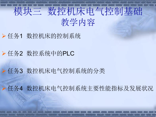
➢ 任务1 数控机床的控制系统
➢ 任务2 数控系统中的PLC
➢ 任务3 数控机床电气控制系统的分类
➢ 任务4 数控机床电气控制系统主要性能指标及发展状况
任务1 数控机床的控制系统
1.数控机床的组成
任务1 数控机床的控制系统
2.数控机床加工过程及特点任务1 数控机床的控制系统
1.运动性能指标 ➢ 1)可控制轴数与联动轴数 ➢ 2)主轴转速 ➢ 3)进给速度 ➢ 4)坐标行程 ➢ 5)刀具容量和换刀时间 2.精度指标 ➢ 1)定位精度 ➢ 2)重复定位精度 ➢ 3)分辨率与脉冲当量 3.数控机床电气控制系统的发展状况 ➢ 1)数控系统的发展状况 ➢ 2)伺服系统的发展状况 ➢ 3)可编程控制器的发展状况
➢2)直线控制系统
任务3 数控机床电气控制系统的分类
➢3)轮廓控制系统
任务3 数控机床电气控制系统的分类
2.按伺服系统分类 ➢1)开环控制系统
任务3 数控机床电气控制系统的分类
➢2)半闭环控制系统
任务3 数控机床电气控制系统的分类
➢3)闭环控制系统
任务4 数控机床电气控制系统主要性能指标及发展状况
3.数控机床的特点 4.数控机床电气控制系统
任务1 数控机床的控制系统
5.机床强电控制系统
6.数控系统辅助功能与PLC
任务2 数控系统中的PLC
1.内装型PLC
任务2 数控系统中的PLC
2.独立型PLC
任务3 数控机床电气控制系统的分类
1.按运动轨迹分类 ➢1)点位控制系统
任务3 数控机床电气控制系统的分类
- 1、下载文档前请自行甄别文档内容的完整性,平台不提供额外的编辑、内容补充、找答案等附加服务。
- 2、"仅部分预览"的文档,不可在线预览部分如存在完整性等问题,可反馈申请退款(可完整预览的文档不适用该条件!)。
- 3、如文档侵犯您的权益,请联系客服反馈,我们会尽快为您处理(人工客服工作时间:9:00-18:30)。
The open-loop control can be used in applications in which there is no change in load conditions,such as the NC , drilling machine.The advantage of the open-loop control . system is that it is less expensive,since it does not require , the additional hardware and electronics needed for positioning feedback.The disadvantage is the difficulty of . detecting a positioning error (Figure 3-1).
Closed-loop systems are very accurate. Most has an automatic compensation for error, since the feedback device indicates the error and the control makes the necessary adjustments to bring the slide back to the position. They use AC, DC or hydraulic servomotors (Figure 3-2). .
Servo motors are connected to the spindle. They are also connected to the machine table through the ball-nut leadscrew. A device called a resolver continuously monitors the amount by which the table and/or spindle has moved and sends this information back to the MCU. The MCU can then adjust its signal as the actual table and/or spindle position approaches the programmed position.[2] Systems that provide feedback signals of this type are called servo systems or servomechanisms. They can position tools with a very high degree of accuracy even when driving motors with highhorsepower ranges.
In the closed-loop control system , the electronic movement pulses are sent from the control to the servomotor, enabling the motor to rotate with each pulse. The movements are detected and counted by a feedback device called a transducer. With each step of movement, a transducer sends a signal back to the control,which compares the current , position of the driven axis with the programmed position. When the number of pulse sent and received match, the control starts sending out pulses for the next movement.
Because the machine automatically knows how to move in response to an axis command, the programmer need not be concerned whether it is the spindle or table that moves. For programming purposes, programmers should consider the CNC machine table as locked with only the tool in the spindle moving along the ±X, ±Y, and ±Z axes. The main point is that the tool arrives at the programmed location. Thus, the machine axis will be defined in terms of spindle movement.
3.2 Lesson 6 Closed-loop Control System ClosedA closed-loop system utilizes the servo motor whose types include AC servo motors, DC servo motors, and hydraulic servo motors. A servo motor does not operate like a pulse counting stepping motor. The speed of an AC or DC servo motor is variable and depends upon the amount of current passing through it. The speed of a hydraulic servo motor depends upon the amount of fluid passing through it. The strength of current coming from the MCU determines the speed at which a servo motor rotates. [1]
1. Primary machine axes of movement should follow the right-hand rule (Figure 3-3). 2. Spindle movement is primarily along the Z axis. Movement into the work is along the-Z axis and movement - away from the work is along the +Z axis. 3. In a majority of milling machines, motion along the X axis is the longest travel perpendicular to Z. Motion indicated by -X is directly opposite to that indicated by + X. The X axis is parallel to the work holding and is in the horizontal plane. The X axis moves to the right along a plane of the work as the operator looks at that plane.
CNC equipment executes machining operations by performing some form of sliding linear motion and rotary motion. The actual method of movement is designed by the manufacturer and can vary from machine to machine. For example, the table can move in the horizontal plane (XY-axis motion) and the spindle in the vertical plane (Z-axis motion). The system will respond to a command to move the spindle (tool) along the +X or +Y axis by moving the table in the opposite direction, -X or-Y. -
The open-loop control systems does not provide positioning feedback to the control unit.The movement . pulses are sent out by the control and they are received by a special type of servomotor called a stepper motor. The number of pulses that the control sends to the stepper motor controls the amount of the rotation of the motor. The stepper motor then proceeds with the next movement command. Since this control system only counts pulses and cannot identify discrepancies in positioning,the machine will , continue this inaccuracy until somebody finds the error. .