ASTM A388A388M-2003大型钢锻件超声波检测的标准实施规程英文
钢材知识ASTMA钢材标准AA
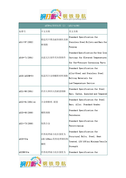
Standard Specification for Seamless 低温设备用无缝与焊接碳素
and Welded Carbon and Alloy-Steel 和合金钢管
Tubes for Low-Temperature Service
Standard Specification for Seamless 高温用无缝铁素体合金钢管 Ferritic Alloy-Steel Pipe for
830Mpa 的热处理钢结构螺栓 Structural Bolts, Steel, Heat Treated 830 Mpa Minimum Tensile Strength [Metric]
铸铁冲击试验方法
Standard Test Methods for Impact Testing of Cast Irons
A356/A356M-98(2003)
合金钢和不锈钢铸件
Stainless Steel, Heavy-Walled for
Steam Turbines
A358/A358M-04
Standard Specification for
Electric-Fusion-Welded Austenitic 高温用电熔焊奥氏体铬镍合
用瓦特计--安培计--伏特计 Standard Test Method for Alternating
法(100-10000 赫兹)和 25 厘 Current Magnetic Properties of
米艾普斯亭框测定材料的交 Materials Using the
流磁性能的试验方法
Wattmeter-Ammeter-Voltmeter
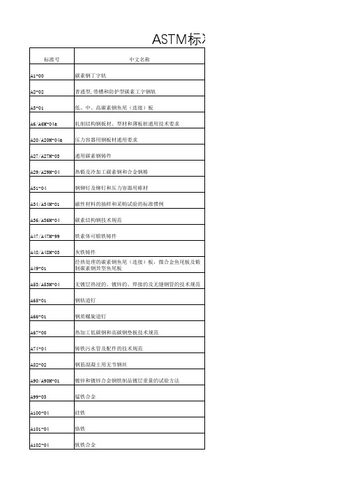
美标A系列对应标准

普通型,带槽和防护型碳素工字钢轨
A3-01(2006)
Carbon (Non-Heat-Treated) Standard Specification for General Requirements for Rolled
低、中、高碳素钢鱼尾(连接)板
A6/A6M-05a
Structural Steel Bars, Plates, Shapes, and Sheet Piling Standard Specification for General Requirements for Steel Plates
标准号 A1-00(2005)
Hale Waihona Puke 英文名称 Standard Specification for Carbon Steel Tee Rails Standard Specification for Carbon Steel Girder Rails of Plain,
中文名称 碳素钢丁字轨
A2-02
Grooved, and Guard Types Standard Specification for Steel Joint Bars, Low, Medium, and High
Steel Plate, Sheet, and Strip Standard Specification for Electric-Resistance-Welded Carbon
不锈钢和耐热铬钢板、薄板及带材 电阻焊接碳素钢钢管及碳锰钢锅炉和过热器管的技
A178/A178M-02
Steel and Carbon-Manganese Steel Boiler and Superheater Tubes 术规范 Standard Specification for Seamless Cold-Drawn Low-Carbon Steel
astma388 标准中文版

astma388 标准中文版一、astma388标准介绍astma388是美国材料和试验协会(ASTM)制定的一项标准,它包括了很多领域的测试方法和规范。
作为一项材料测试标准,astma388旨在确保各种材料在制造和使用过程中能够满足相应的技术要求,以保证产品的质量和安全性。
二、astma388标准的用途1. astma388标准被广泛应用于工业、建筑、航空航天、能源等领域,以进行各种材料的物理性能、化学性能、热处理性能等方面的测试和评估。
2. astma388标准也被广泛应用于科研机构、高校实验室等科学研究领域,用于对各种新材料的性能进行测试和分析,为新材料的开发和应用提供支持。
三、astma388标准的主要内容astma388标准主要包括以下方面的内容:1. 试样的制备:标准中对试样的制备方法进行了详细的规定,包括试样的尺寸、形状、加工工艺等方面的要求,以确保测试结果的准确性和可比性。
2. 物理性能测试:包括拉伸性能、弯曲性能、硬度、冲击性能等方面的测试方法,在标准中对相关测试装置、试验条件等都进行了规定,以确保测试结果的准确性和可重复性。
3. 化学性能测试:包括化学成分分析、腐蚀性能测试等方面的方法,对相关试剂、仪器设备的要求也在标准中进行了详细规定。
4. 热处理性能测试:包括金相组织观察、晶粒度测定、显微硬度测定等方法,对相关设备、试验条件等方面也进行了详细规定。
5. 样品标签和记录:对测试样品的标识、记录和报告的要求也在标准中进行了规定,以确保测试数据的可追溯性和可靠性。
四、astma388标准的意义1. astma388标准的制定和应用,能够确保各种材料的性能测试能够按照统一的标准进行,从而保证了测试结果的可比性和可重复性。
2. astma388标准的应用,能够为材料的生产、加工和使用提供科学依据,保证产品的质量和安全性,促进材料技术的发展和进步。
3. astma388标准的推广,能够促进国际间材料测试方法的统一,为国际贸易和合作提供了技术支持和保障。
A388中文版
ASTM A388/A388M-03大型锻钢件的超声波检测方法1适用范围1.1本标准适用于采用直射波和斜射波技术对大型锻钢件作接触式、脉冲回波超声波检测。
1.2凡是因咨询、合同、订货或技术条件的规定,而要求对锻件按A388/A388M进行超声波检测时,均可采用本标准。
1.3以英寸—磅为单位,或以SI国际单位制表示的数值均视为标准值。
在正文中,SI国际单位制数值表示在括号内。
用上述二种单位制表示的数值并不完全相等,因此只能单独使用其中一种。
混同使用两种单位制可能会使之与技术要求不一致。
1.4本标准及引用的材料技术条件均同时采用英寸—磅和SI国际单位制表述,然而除非订单技术要求中规定采用SI国际单位制,所用材料应以英寸—磅为供货单位。
1.5本标准的宗旨不在于论述与使用有关的安全问题。
使用本标准者在使用前有责任制订相应的有关安全防护与保健的措施,并确定有关应用范围的管理条例。
2参考文献2.1ASTM标准A469 发电机转子用真空精炼钢锻件的技术要求A745/A745M 奥氏体钢锻件的超声波检验方法E317 不采用电子测量装置评价脉冲反射式超声波检测装置及系统性能的检测方法E428 超声波检测用钢制参考试块的制作和控制方法2.2ANSI标准B46.1 表面状况2.3其它文献无损检测人员资格与鉴定的推荐方法SNT-TC-1A,附录C——超声波检测3订货依据3.1当采用本标准应用于咨询、合同或订货时,订货方应申明并提供下列各项资料。
3.1.1按照7.2.2和7.3.3条(V形或矩形槽)所述来确定灵敏度的方法。
3.1.1.1按照7.2.2.2条所述确定参考试块的材料、平底孔孔径及其金属测试声程。
3.1.2按照10.3条所述确定整个锻件或其中某些部位的质量等级。
3.1.3根据6.1、6.2和7.1.11条规定的任何选择方案。
4仪器4.1本检测应采用脉冲反射式超声波仪器。
仪器应至少具有1~5MHz频率下进行检测的能力。
astm锻件超声波验收标准-概述说明以及解释

astm锻件超声波验收标准-概述说明以及解释1.引言1.1 概述在现代制造业中,质量控制是至关重要的一环。
而超声波验收技朮是一种非破坏性检测技朮,被广泛应用于工业生产中。
ASTM锻件超声波验收标准作为一项重要的标准,规范了在锻件制造过程中进行超声波验收的操作步骤和要求。
本文将重点介绍ASTM锻件超声波验收标准的相关内容,探讨超声波验收在工业生产中的重要性以及应用范围。
通过深入分析和探讨,旨在为读者提供对ASTM锻件超声波验收标准的全面了解,进一步推动该技朮的应用与发展。
1.2 文章结构本文主要分为三个部分,分别为引言、正文和结论。
在引言部分,我们将简要介绍ASTM锻件超声波验收标准的背景和意义,概述本文的结构,并阐明本文的研究目的。
正文部分将重点介绍ASTM锻件超声波验收标准的内容和要求,探讨超声波验收在锻件制造领域的重要性和应用范围,并分析其在提高锻件质量和工艺控制方面的作用。
结论部分将对本文的主要观点进行总结,展望ASTM锻件超声波验收标准在未来的发展前景,以及对读者提出对超声波验收技术的进一步思考和探讨。
通过以上分析,本文将全面探讨ASTM锻件超声波验收标准的相关内容,为读者提供深入了解和应用该标准的指导和参考。
1.3 目的:本文旨在介绍ASTM锻件超声波验收标准的相关知识,探讨超声波验收在锻件行业中的重要性以及应用范围。
通过对ASTM锻件超声波验收标准的介绍和分析,希望读者能够更深入地了解超声波验收技术在锻件生产过程中的作用,从而提高产品质量,确保生产安全,促进行业发展。
同时,也为未来锻件超声波验收技术的研究和应用提供一定参考和借鉴。
2.正文2.1 ASTM锻件超声波验收标准介绍在工业制造领域,ASTM(美国材料与试验协会)锻件超声波验收标准是一项重要的质量控制方法。
这项标准旨在通过使用超声波技术来检查锻件的内部缺陷,以确保其质量符合规定的标准。
ASTM锻件超声波验收标准主要包括两个方面:一是规定超声波检测设备的性能要求和使用方法,二是明确了不同类型的锻件应采取何种超声波检测方法来进行验收。
A388

STANDARD PRACTICE FOR ULTRASONIC EXAMINATION OF HEA VYSTEEL FORGINGS重型锻造钢的探伤测试标准惯例1. Scope 范围1.1 This practice covers the examination procedures for the contact, pulse-echo ultrasonic examination of heavy steel forgings by the straight and angle-beam techniques.本惯例包含了通过直探头和斜探头的重型锻造钢的接触和回波探伤测试的程序。
1.2 This practice is to be used whenever the inquiry, contract, order, or specification states that forgings are to be subject to ultrasonic examination in accordance with ASTM Practice A 388.这份惯例在当询盘、合同、订单或明细中声明锻造钢需要根据ASTM A 388进行探伤测试时使用。
1.3 The values stated in either inch-pound or SI units are to be regarded as the standard. Within the text, the SI units are shown in brackets. The values stated in each system are not exact equivalents; therefore, each system must be used independently of the other. Combining values from the two systems may result in nonconformance with the specification.以英制或SI制单位标识的数值均为标准数值,两种单位表示的数值不准确相等,因此每种单位必须单独使用。
ASTM A388(2005中文版) 大型钢锻件超声检测标准操作方法
ASTM A 388-05大型钢锻件超声检测标准操作方法1 适用范围1.1 本操作方法包括用直射波和斜射波技术对大型钢锻件作接触式脉冲回波式超声波检测规程。
直声波法包括DGS(距离-增益-当量)法。
见附录X31.2 凡因询价,合同,订货或技术条件的规定要求按照ASTM A388/A388M 进行超声检测时,均用采用本操作方法。
1.3 以英制或SI 制单位表示的数值均为标准数值,两种单位表示的数值不准确相等,因此每种单位必须单独使用。
两种单位组合使用产生的结果可能和本方法不一致。
1.4 本方法和材料规范均用英制和SI 制表示。
但除了订货规范采用规范符号M(SI)外,应使用英制加工材料。
1.5 本标准不是关于与使用有关的安全问题,使用本标准的用户有责任在使用前建立适当的安全健康操作方法并确定这种方法的可行性。
2.引用文件2.1ASTM 标准A469/A 469M 发电机用钢锻件真空熔炼技术规范A745/A745M 奥氏体钢锻件的超声检测操作方法E317 无电子测量设备的脉冲回波式超声检测系统性能评定操作方法。
E428 超声检测用参考试块的制作和质量控制操作方法。
E 1065 超声检测探头的性能评定指南。
2.2 ANSI 标准(美国国家标准)B 46.1 表面结构2.3 其它文件推荐的无损检测人员资格鉴定和认证的操作方法SNT-TC-1A(1988 版或其后的)3.术语单个指示—指当探头沿任何方向移动时波幅从最高点下降至一定波高的一个指示,由于太小被认为非平面型指示或游动指示。
密集型指示—指在锻件边长2in(50mm)的立方体内或更小体积内有五个或更多的指示平面型指示—指指示的最大长度大于1in[25mm]或大于探头主要尺寸两倍的指示,但无论哪种都不是游动的指示。
游动指示—指探头在锻件表面移动时波的前沿在工件深度方向上移动1in[25mm]或更多距离的指示。
4.订货信息4.1 当本方法用于询价签合同,订货时,订货单位应当声明,并提供如下信息:4.1.1 标准数据(包括日期)4.1.2 按照8.2.2 和8.3.3 确定探伤灵敏度的方法。
国外主要无损检测标准题录(超声检测)
ASTM B509-77 核用镍合金板材补充要求的规范
ASTM B510-77 核用镍合金棒材补充要求的规范
ASTM B513-77 核用镍合金无缝管材补充要求的规范
ASTM C597-83(91) 混凝士中脉冲速度的测试方法(C-9)
ASTM E1139-2002 声发射连续监视金属压力极限的技术规程
ASTM E1118-2000 增强型热固树脂管(RTRP) 声发射检验技术规程
ASTM E1158-2004 金属和合金材料超声脉冲纵波检验用参考试块材料选择和制作指南
ASTM E1315-93(2002) 凸圆柱曲面钢材的超声波检查技术规程
ASTM E2001-1998(2003) 谐振超声波频谱技术用于金属和非金属零件中探测缺陷的指南
ASTM E2075-2000 应用聚丙烯棒检定声发射传感器响应稳定性的技术规程
ASTM E2076-2000 应用声发射检查玻璃纤维增强塑料风扇叶片的标准试验方法
ASTM E2191-2002 卷绕覆合层充气压力容器声发射标准检测方法
ASME 2235:2000 超声衍射时差(TOFD)法
ASME 2235-4:2001 锅炉压力容器规范案例 用超声检验取代射线照相[S]
MIL-STD-1263-73 超声检测人员的资格鉴定与证书颁发(已停用)
MIL-I-46175-76 SAE D 7003球墨铸铁的超声检测
ASTM E1324-2000 测量超声波检查仪若干电子特性的指南
ASTM E1454-2002 数字超声检验数据计算机化传输的数据区指南
ASTM E1419-2002b 利用声发射检验无缝充气压力容器的标准试验方法
ASTM A388-05大型钢锻件超声测试操作标准
大型钢锻件超声测试操作标准1.范围1.1本操作方法包括用直射波和斜射波技术对大型钢锻件做接触式,脉冲回波式超声波检测流程。
直射波技术包括DGS(距离-增益-当量)方法。
见附录X3。
1.2凡因询价,合同,订货或技术条件的规定要求按照ASTM A388/A388M进行超声检测时,均采用本操作方法。
1.3以SI制单位或英制单位表示的数值均为标准数值。
两种单位表示的数值不完全相等;因此每种单位必须单独使用。
两种单位组合使用产生的结果可能和该标准不符。
1.4本方法和材料规范均用SI制和英制表示。
但除了订货要求采用规范符号M(SI)外,应使用英制单位加工。
1.5本标准不是讨论安全问题,如果有,是与使用有关的。
使用本标准的用户有责任在使用前建立适当的安全健康操作方法并确定这种方法的可行性。
2.引用文件2.1ASTM 标准:A 469/A 469M 发电机用钢锻件真空熔炼技术规范A 745/A 745M 奥氏体钢锻件的超声检测操作方法E 317 无电子测量设备的脉冲回波式超声检测系统性能评定操作方法E 428 超声检测用参考试块的制作和质量控制操作方法E 1065 超声检测探头的性能评定指南2.2ANSI 标准:B 46.1 表面结构2.3其他文件推荐的无损检测人员资格鉴定和认证的操作方法SNT-TC-1A,(1988版或以后的)3.术语3.1定义:3.1.1单个指示—指当探头沿任何方向移动时波幅从最高点下降至一定波高的一个指示,由于太小不看作游动指示或平面指示。
3.1.2指示级别(密集型指示)—-指在锻件边长2in(50mm)的立方体内或更小体积内有五个或更多的指示。
3.1.3平面型指示—指指示的最大长度大于1in(25mm)或大于探头主要尺寸两倍的指示,但无论哪种都不是游动的指示。
3.1.4游动指示—指探头在锻件表面移动时波的前沿在工件探度方向上移动1in(25mm)或更多距离的指示。
4.订货信息4.1当本方法用于询价签合同,订货时,订货单位应当声明,并提供如下信息:4.1.1标准数据(包括日期)4.1.2按照8.2.2和8.3.3确定探伤灵敏度。
ASTM A 388-A388M-2009_钢锻件超声波检查规程

Designation:A388/A388M–09Used in USNRC-RDT standards Standard Practice forUltrasonic Examination of Steel Forgings1This standard is issued under thefixed designation A388/A388M;the number immediately following the designation indicates the yearof original adoption or,in the case of revision,the year of last revision.A number in parentheses indicates the year of last reapproval.A superscript epsilon(´)indicates an editorial change since the last revision or reapproval.1.Scope*1.1This practice2covers the examination procedures for the contact,pulse-echo ultrasonic examination of steel forgings by the straight and angle-beam techniques.The straight beam techniques include utilization of the DGS(Distance Gain-Size) method.See Appendix X3.1.2This practice is to be used whenever the inquiry, contract,order,or specification states that forgings are to be subject to ultrasonic examination in accordance with Practice A388/A388M.1.3The values stated in either SI units or inch-pound units are to be regarded separately as standard.The values stated in each system may not be exact equivalents;therefore,each system shall be used independently of the bining values from the two systems may result in non-conformance with the standard.1.4This specification and the applicable material specifica-tions are expressed in both inch-pound units and SI units. However,unless the order specifies the applicable“M”speci-fication designation[SI units],the material shall be furnished to inch-pound units.1.5This standard does not purport to address all of the safety concerns,if any,associated with its use.It is the responsibility of the user of this standard to establish appro-priate safety and health practices and determine the applica-bility of regulatory limitations prior to use.2.Referenced Documents2.1ASTM Standards:3A469/A469M Specification for Vacuum-Treated Steel Forgings for Generator RotorsA745/A745M Practice for Ultrasonic Examination of Aus-tenitic Steel ForgingsE317Practice for Evaluating Performance Characteristics of Ultrasonic Pulse-Echo Testing Instruments and Systems without the Use of Electronic Measurement Instruments E428Practice for Fabrication and Control of Metal,Other than Aluminum,Reference Blocks Used in Ultrasonic TestingE1065Guide for Evaluating Characteristics of Ultrasonic Search Units2.2ANSI Standard:B46.1Surface Texture42.3Other Document:Recommended Practice for Nondestructive Personnel Quali-fication and Certification SNT-TC-1A,(1988or later)5 3.Terminology3.1Definitions:3.1.1indication levels(clusters),n—five or more indica-tions in a volume representing a2-in.[50-mm]or smaller cube in the forging.3.1.2individual indications,n—single indications showinga decrease in amplitude as the search unit is moved in any direction from the position of maximum amplitude and which are too small to be considered traveling or planar.3.1.3planar indications,n—indications shall be considered continuous over a plane if they have a major axis greater than 1in.[25mm]or twice the major dimension of the transducer, whichever is greater,and do not travel.3.1.4traveling indications,n—inductions whose leading edge moves a distance equivalent to1in.[25mm]or more of metal depth with movement of the transducer over the surface of the forging.4.Significance and Use4.1This practice shall be used when ultrasonic inspection is required by the order or specification for inspection purposes where the acceptance of the forging is based on limitations of the number,amplitude,or location of discontinuities,or a combination thereof,which give rise to ultrasonic indications.1This practice is under the jurisdiction of ASTM Committee A01on Steel, Stainless Steel and Related Alloys and is the direct responsibility of Subcommittee A01.06on Steel Forgings and Billets.Current edition approved May1,2009.Published May2009.Originally approved st previous edition approved in2008as A388/A388M–08.2For ASME Boiler and Pressure Vessel Code applications see related Specifi-cation SA-388/SA-388M in Section II of that Code.3For referenced ASTM standards,visit the ASTM website,,or contact ASTM Customer Service at service@.For Annual Book of ASTM Standards volume information,refer to the standard’s Document Summary page on the ASTM website.4Available from American National Standards Institute(ANSI),25W.43rd St., 4th Floor,New York,NY10036.5Available from the American Society for Nondestructive Testing,1711Arlin-gate Ln.,P.O.Box28518,Columbus,OH43228–0518.*A Summary of Changes section appears at the end of this standard. Copyright©ASTM International,100Barr Harbor Drive,PO Box C700,West Conshohocken,PA19428-2959,United States.4.2The ultrasonic quality level shall be clearly stated as order requirements.5.Ordering Information5.1When this practice is to be applied to an inquiry, contract,or order,the purchaser shall so state and shall also furnish the following information:5.1.1Designation number(including year date),5.1.2Method of establishing the sensitivity in accordance with9.2.2and9.3.3(Vee-or rectangular-notch),5.1.2.1The diameter and test metal distance of theflat-bottom hole and the material of the reference block in accordance with9.2.2.2,5.1.3Quality level for the entire forging or portions thereof in accordance with12.3,and5.1.4Any options in accordance with1.4,6.4,6.5,7.1,8.1, 8.2,9.1.11,10.1,and10.2.6.Apparatus6.1An ultrasonic,pulsed,reflection type of instrument shall be used for this examination.The system shall have a mini-mum capability for examining at frequencies from1to5MHz. On examining austenitic stainless forgings the system shall have the capabilities for examining at frequencies down to0.4 MHz.6.1.1The ultrasonic instrument shall provide linear presen-tation(within5%)for at least75%of the screen height (sweep line to top of screen).The5%linearity referred to is descriptive of the screen presentation of amplitude.Instrument linearity shall be verified in accordance with the intent of Practice E317.Any set of blocks processed in accordance with Practice E317or E428may be used to establish the specified 65%instrument linearity.6.1.2The electronic apparatus shall contain an attenuator (accurate over its useful range to610%(+1dB)of the amplitude ratio)which will allow measurement of indications beyond the linear range of the instrument.6.2Search Units,having a transducer with a maximum active area of1in.2[650mm2]with3⁄4in.[20mm]minimum to11⁄8in.[30mm]maximum dimensions shall be used for straight-beam scanning(see9.2);and search units with1⁄2in. [13mm]minimum to1in.[25mm]maximum dimensions shall be used for angle-beam scanning(see9.3).6.2.1Transducers shall be utilized at their rated frequencies.6.2.2Other search units may be used for evaluating and pinpointing indications.6.3Couplants,having good wetting characteristics such as SAE No.20or No.30motor oil,glycerin,pine oil,or water shall be used.Couplants may not be comparable to one another and the same couplant shall be used for calibration and examination.6.4Reference Blocks,containingflat-bottom holes may be used for calibration of equipment in accordance with6.1.1and may be used to establish recording levels for straight-beam examination when so specified by the order or contract.6.5DGS Scales,matched to the ultrasonic test unit and transducer to be utilized,may be used to establish recording levels for straight beam examination,when so specified by the order or contract.The DGS scale range must be selected to include the full thickness cross-section of the forging to be examined.An example of a DGS overlay is found in Appendix X3.6.5.1As an alternative to using DGS overlays,an ultrasonic instrument having integral decibel gain or attenuator controls in combination with a specifically paired transducer and DGS diagram may be used to evaluate ultrasonic indications.7.Personnel Requirements7.1Personnel performing the ultrasonic examinations to this practice shall be qualified and certified in accordance with a written procedure conforming to Recommended Practice No. SNT-TC-1A(1988or later)or another national standard that is acceptable to both the purchaser and the supplier.8.Preparation of Forging for Ultrasonic Examination 8.1Unless otherwise specified in the order or contract,the forging shall be machined to provide cylindrical surfaces for radial examination in the case of round forgings;the ends of the forgings shall be machined perpendicular to the axis of the forging for the axial examination.Faces of disk and rectangular forgings shall be machinedflat and parallel to one another.8.2The surface roughness of exteriorfinishes shall not exceed250µin.[6µm]unless otherwise shown on the forging drawing or stated in the order or the contract.8.3The surfaces of the forging to be examined shall be free of extraneous material such as loose scale,paint,dirt,and so forth.9.Procedure9.1General:9.1.1As far as practicable,subject the entire volume of the forging to ultrasonic examination.Because of radii at change of sections and other local configurations,it may be impossible to examine some sections of a forging.9.1.2Perform the ultrasonic examination after heat treat-ment for mechanical properties(exclusive of stress-relief treatments)but prior to drilling holes,cutting keyways,tapers, grooves,or machining sections to contour.If the configuration of the forging required for the treatment for mechanical properties prohibits a subsequent complete examination of the forging,it shall be permissible to examine prior to treatment for mechanical properties.In such cases,reexamine the forging ultrasonically as completely as possible after heat treatment.9.1.3To ensure complete coverage of the forging volume, index the search unit with at least15%overlap with each pass.9.1.4For manual scanning,do not exceed a scanning rate of 6in./s[150mm/s].9.1.5For automated scanning,adjust scanning speed or instrument repetition rate,or both,to permit detection of the smallest discontinuities referenced in the specification and to allow the recording or signaling device to function.At no time shall the scanning speed exceed the speed at which an acceptable calibration was made.9.1.6If possible,scan all sections of forgings in two perpendicular directions.9.1.7Scan disk forgings using a straight beam technique from at least oneflat face and radially from the circumference, wheneverpracticable.9.1.8Scan cylindrical sections and hollow forgings radially using a straight-beam technique.When practicable,also exam-ine the forging in the axial direction.9.1.9In addition,examine hollow forgings by angle-beam technique from the outside diameter surface as required in 9.3.1.9.1.10In rechecking or reevaluation by manufacturer or purchaser,use comparable equipment,search units,frequency, and couplant.9.1.11Forgings may be examined either stationary or while rotating in a lathe or on rollers.If not specified by the purchaser,either method may be used at the manufacturer’s option.9.2Straight-Beam Examination:9.2.1For straight-beam examination use a nominal21⁄4-MHz search unit whenever practicable;however,1MHz is the preferred frequency for coarse grained austenitic materials and long testing distances.In many instances on examining coarse grained austenitic materials it may be necessary to use a frequency of0.4MHz.Other frequencies may be used if desirable for better resolution,penetrability,or detectability of flaws.9.2.2Establish the instrument sensitivity by either the reflection,reference-block technique,or DGS method(see Appendix X3for an explanation of the DGS method).9.2.2.1Back-Reflection Technique(Back-Reflection Cali-bration Applicable to Forgings with Parallel Entry and Back Surfaces)—With the attenuator set at an appropriate level,for example5to1or14dB,adjust the instrument controls to obtain a back reflection approximately75%of the full-screen height from the opposite side of the forging.Scan the forging at the maximum amplification setting of the attenuator(attenu-ator set at1to1).Carry out the evaluation of discontinuities with the gain control set at the reference level.Recalibration is required for significant changes in section thickness or diam-eter.N OTE1—High sensitivity levels are not usually employed when in-specting austenitic steel forgings due to attendant high level of“noise”or “hash”caused by coarse grain structure.9.2.2.2Reference-Block Calibration—The test surface roughness on the calibration standard shall be comparable to, but no better than,the item to be examined.Adjust the instrument controls to obtain the required signal amplitude from theflat-bottom hole in the specified reference block. Utilize the attenuator in order to set up on amplitudes larger than the vertical linearity of the instrument.In those cases, remove the attenuation prior to scanning the forging.N OTE2—Whenflat-surfaced reference block calibration is specified, adjust the amplitude of indication from the reference block or blocks to compensate for examination surface curvature(an example is given in Appendix X1).9.2.2.3DGS Calibration—Prior to use,verify that the DGS overlay matches the transducer size and frequency.Accuracy of the overlay can be verified by reference blocks and procedures outlined in Practice E317.Overlays are to be serialized to match the ultrasonic transducer and pulse echo testing system that they are to be utilized with.9.2.2.4Choose the appropriate DGS scale for the cross-sectional thickness of the forging to be examined.Insert the overlay over the CRT screen,ensuring the DGS scale base line coincides with the sweep line of the CRT screen.Place the probe on the forging,adjust the gain to make thefirst back-wall echo appear clearly on CRT ing the Delay and Sweep control,shift the screen pattern so that the leading edge of the initial pulse is on zero of the DGS scale and the back-wall echo is on the DGS scale value corresponding to the thickness of the forging.Adjust the gain so the forging back-wall echo matches the height of the DGS reference slope within61Db.Once adjusted,increase the gain by the Db shown on the DGS scale for the reference slope.Instrument is now calibrated andflaw sizes that can be reliably detected can be directly read from the CRT screen.Theseflaw sizes are the equivalentflat bottom reflector that can be used as a reference point.N OTE3—The above can be utilized on all solid forgings.Cylindrical hollow forgings,and drilled or bored forgings must be corrected to compensate for attenuation due to the central hole(see Appendix X4).9.2.3Recalibration—Any change in the search unit,cou-plant,instrument setting,or scanning speed from that used for calibration shall require recalibration.Perform a calibration check at least once every8h shift.When a loss of15%or greater in the gain level is indicated,reestablish the required calibration and reexamine all of the material examined in the preceding calibration period.When an increase of15%or greater in the gain level is indicated,reevaluate all recorded indications.9.2.4During the examination of the forging,monitor the back reflection for any significant reduction in amplitude. Reduction in back-reflection amplitude may indicate not only the presence of a discontinuity but also poor coupling of the search unit with the surface of the forging,nonparallel back-reflection surface,or local variations of attenuation in the forging.Recheck any areas causing loss of back reflection.9.3Angle-Beam Examination—Rings and Hollow Forgings: 9.3.1Perform the examination from the circumference of rings and hollow forgings that have an axial length greater than 2in.[50mm]and an outside to inside diameter ratio of less than2.0to1.9.3.2Use a1MHz,45°angle-beam search unit unless thickness,OD/ID ratio,or other geometric configuration results in failure to achieve calibration.Other frequencies may be used if desirable for better resolution,penetrability,or detectability offlaws.For angle-beam inspection of hollow forgings up to 2.0to1ratio,provide the transducer with a wedge or shoe that will result in the beam mode and angle required by the size and shape of the cross section under examination.9.3.3Calibrate the instrument for the angle-beam examina-tion to obtain an indication amplitude of approximately75% full-screen height from a rectangular or a60°V-notch on inside diameter(ID)in the axial direction and parallel to the axis of the forging.A separate calibration standard may be used; however,it shall have the same nominal composition,heat treatment,and thickness as the forging it represents.The test surfacefinish on the calibration standard shall be comparable but no better than the item to be examined.Where a groupof --` , , ` ` ` , , , ` , ` ` ` , ` , ` , ` ` , , ` ` ` ` ` -` -` , , ` , , ` , ` , , ` ---identical forgings is made,one of these forgings may be used as the separate calibration standard.Cut the ID notch depth to 3%maximum of the thickness or1⁄4in.[6mm],whichever is smaller,and its length approximately1in.[25mm].Thickness is defined as the thickness of the forging to be examined at the time of examination.At the same instrument setting,obtain a reflection from a similar OD notch.Draw a line through the peaks of thefirst reflections obtained from the ID and OD notches.This shall be the amplitude reference line.It is preferable to have the notches in excess metal or test metal when possible.When the OD notch cannot be detected when examining the OD surface,perform the examination when practicable(some ID’s may be too small to permit examina-tion),as indicated above from both the OD and ID surfaces. Utilize the ID notch when inspecting from the OD,and the OD notch when inspecting from the ID.Curve wedges or shoes may be used when necessary and practicable.9.3.4Perform the examination by scanning over the entire surface area circumferentially in both the clockwise and counter-clockwise directions from the OD surface.Examine forgings,which cannot be examined axially using a straight beam,in both axial directions with an angle-beam search unit. For axial scanning,use rectangular or60°V-notches on the ID and OD for the calibration.These notches shall be perpendicu-lar to the axis of the forging and the same dimensions as the axial notch.10.Recording10.1Straight-Beam Examination—Record the following in-dications as information for the purchaser.These recordable indications do not constitute a rejectable condition unless negotiated as such in the purchase order or contract.10.1.1For individual indications,report:10.1.1.1In the back-reflection technique,individual indica-tions equal to or exceeding10%of a nominal back reflection from an adjacent area free from indications,and10.1.1.2In the reference-block or DGS technique,indica-tions equal to or exceeding100%of the reference amplitude.10.1.2For indications that are planar,traveling,or clustered, determine the location of the edges and the major and minor axes using the half-amplitude(6dB drop)technique and report: 10.1.2.1The variation in depth or planar area,or both,of traveling indications,10.1.2.2The length of major and minor axes of planar indications,and10.1.2.3The volume occupied by indication levels and the amplitude range.10.2Angle-Beam Examination—Record discontinuity indi-cations equal to or exceeding50%of the indication from the reference line.When an amplitude reference line cannot be generated,record discontinuity indications equal to or exceed-ing50%of the reference notch.These recordable indications do not constitute a rejectable condition unless negotiated as such in the purchase order.10.3Report reduction in back reflection exceeding50%of the original measured in increments of10%.10.4When recording,corrections must be made for beam divergence at the estimatedflaw depth(See Guide E1065).10.5Report indication amplitudes in increments of10%.11.Report11.1Report the following information:11.1.1All recordable indications(see Section10);11.1.2For the purpose of reporting the locations of record-able indications,a sketch shall be prepared showing the physical outline of the forging including dimensions of all areas not inspected due to geometric configuration,the pur-chaser’s drawing number,the purchaser’s order number,and the manufacturer’s serial number,and the axial,radial,and circumferential distribution of recordable ultrasonic indica-tions;11.1.3The designation(including year date)to which the examination was performed as well as the frequency used, method of setting sensitivity,type of instrument,surfacefinish, couplant,and search unit employed;and11.1.4The inspector’s name or identity and date the exami-nation was performed.12.Quality Levels12.1This practice is intended for application to forgings, with a wide variety of sizes,shapes,compositions,melting processes,and applications.It is,therefore,impracticable to specify an ultrasonic quality level which would be universally applicable to such a diversity of products.Ultrasonic accep-tance or rejection criteria for individual forgings should be based on a realistic appraisal of service requirements and the quality that can normally be obtained in the production of the particular type forging.12.2Austenitic stainless steel forgings are more difficult to penetrate ultrasonically than similar carbon or low-alloy steel forgings.The degree of attenuation normally increases with section size;and the noise level,generally or in isolated areas, may become too great to permit detection of discrete indica-tions.In most instances,this attenuation results from inherent coarse grained microstructure of these austenitic alloys.For these reasons,the methods and standards employed for ultra-sonically examining carbon and low-alloy steel forgings may not be applicable to austenitic steel forgings.In general,only straight beam inspecting using a back-reflection reference standard is used.However,utilization of Practice A745/ A745M for austenitic steel forgings can be considered ifflat bottom hole reference standards or angle beam examination of these grades are required.12.3Acceptance quality levels shall be established between purchaser and manufacturer on the basis of one or more of the following criteria.12.3.1Straight-Beam Examination:12.3.1.1No indications larger than some percentage of the reference back reflection.12.3.1.2No indications equal to or larger than the indication received form theflat-bottom hole in a specific reference block or blocks.12.3.1.3No areas showing loss of back reflection larger than some percentage of the reference back reflection.12.3.1.4No indications per12.3.1.1or12.3.1.2coupled with some loss of resultant back reflection per12.3.1.3. 12.3.1.5No indications exceeding the reference level speci-fied in the DGSmethod12.3.2Angle-Beam Examination—No indications exceed-ing a stated percentage of the reflection from a reference notch or of the amplitude reference line.12.4Intelligent application of ultrasonic quality levels in-volves an understanding of the effects of many parameters on examination results.13.Keywords13.1angle beam examination;back-reflection;DGS; reference-block;straight beam examination;ultrasonicSUPPLEMENTARY REQUIREMENTSThe following supplementary requirements shall apply only when specified by the purchaser in the inquiry,contract,or order.Details shall be agreed upon by the manufacturer and the purchaser.S1.Reporting CriteriaS1.1Reference block calibration shall be performed using at least three holes,spaced to approximate minimum,mean, and maximum thickness as tested,and shall be used to generate a distance amplitude correction(DAC)curve.The following hole sizes apply:1.1⁄16in.[1.5mm]flat bottom holes(FBH)for thicknesses lessthan1.5in.[40mm]2.1⁄8in.[3mm]FBH for thicknesses of1.5-6in.[40-150mm]inclusive3.1⁄4in.[6mm]FBH for thicknesses over6in.[150mm]S1.2Reporting criteria include:1.All indications exceeding the DAC curve2.Two or more indications separated by1⁄2in.[12mm]or lessAPPENDIXES(Nonmandatory Information)X1.TYPICAL TUNING LEVEL COMPENSATION FOR THE EFFECTS OF FORGING CURV ATURE X1.1The curve(Fig.X1.1)was determined for the follow-ing test conditions:Material nickel-molybdenum-vanadium alloy steel(Specification A469/A469M,Class4)Instrument Type UR ReflectoscopeSearch unit11⁄8-in.[30-mm]diameter quartzFrequency21⁄4MHzReference block ASTM No.3-0600(aluminum)Reflection area of refer-ence curve 0.010in.2[6.5mm2]in nickel-molybdenum-vana-dium alloy steelSurfacefinish250µin.[6µm],max,roughnessX1.2To utilize curve,adjust reflectoscope sensitivity to obtain indicated ultrasonic response on ASTM No.3-0600 reference block for each diameter as shown.A response of1in. [25mm]sweep-to-peak is used forflat e attenuator to obtain desired amplitude,but do testing at1to1setting.FIG.X1.1Typical Compensation Curve for Effects of ForgingCurvature--`,,```,,,`,```,`,`,``,,`````-`-`,,`,,`,`,,`---X2.INDICATION AMPLITUDE COMPENSATION FOR TEST DISTANCE V ARIATIONSX2.1The curve (Fig.X2.1)has been determined for the following test conditions:Materialnickel-molybdenum-vanadium alloy steel (Specification A 469/A 469M ,Class 4)Instrument Type UR ReflectoscopeSearch unit 11⁄8-in.[30-mm]diameter quartz Frequency 21⁄4MHz CouplantNo.20oilReference blockASTM No.3-0600(aluminum)Reflection area of refer-ence curve 0.010in.2[65mm 2]in nickel-molybdenum-vana-dium alloy steelSurface finish250µin.max,roughnessX2.2To utilize curve,establish amplitude from ASTM reference block to coincide with values from Appendix X1.X3.BACKGROUND INFORMATION ON THE DGSMETHODSFIG.X2.1Typical Distance-Amplitude CorrectionCurveFIG.X3.1Example of DGSOverlay--`,,```,,,`,```,`,`,``,,`````-`-`,,`,,`,`,,`---X3.1The overlay in Fig.X3.1was designed for a 2.0MHz,1in.[25mm]diameter probe and a maximum test distance of 39.4in.[1000mm].In order to use this overlay,the sweep time base must be accurately calibrated and aligned with the overlay being used.The back reflection is then adjusted to either the RE +10dB line or the RE +20dB line,based on the thickness being tested;additional gain (10or 20dB)is added asdesignated by the line being used.The RE +20line covers a range to approximately 15.7in.[400mm]and the RE +10line from 15.7to 39.4in.[400to 1000mm].At this calibration level,the flaw size is read directly from the screen.Flaw sizes from 0.078to 1in.[2to 25mm]can be read directly from the overlay.PENSATION FOR CENTER HOLE ATTENUATION ON CYLINDRICAL BORED OR HOLLOW FORGINGSUTILIZING THE DGS METHODX4.1The hole in a cylindrical bored forging causes sound scatter.In these cases,a correction is required which depends on the wall thickness and bore diameter.X4.1.1Determine the correction value in dB from the Nomogram (Fig.X4.1).With the gain-dB control,proceed as described in 9.2.2.4reducing the flaw detector gain by the correction valuedetermined.N OTE —Metric units are presented in this figure to be consistent with DGS scales presently available.Conversion to English units would also be acceptable.FIG.X4.1The Influence of a Central Bore on the Backwall Echo Amplitude of Cylindrical or Plane ParallelForgings--`,,```,,,`,```,`,`,``,,`````-`-`,,`,,`,`,,`---SUMMARY OF CHANGESCommittee A01has identified the location of selected changes to this standard since the last issue (A 388/A 388M –08)that may impact the use of this standard.(Approved May 1,2009.)(1)Added 6.5.1.Committee A01has identified the location of selected changes to this standard since the last issue (A 388/A 388M –07)that may impact the use of this standard.(Approved Nov.1,2008.)(1)Dropped the term heavy from the title and body of the standard.(2)Added Significance and Use (Section 4).ASTM International takes no position respecting the validity of any patent rights asserted in connection with any item mentioned in this ers of this standard are expressly advised that determination of the validity of any such patent rights,and the risk of infringement of such rights,are entirely their own responsibility.This standard is subject to revision at any time by the responsible technical committee and must be reviewed every five years and if not revised,either reapproved or withdrawn.Your comments are invited either for revision of this standard or for additional standards and should be addressed to ASTM International Headquarters.Your comments will receive careful consideration at a meeting of the responsible technical committee,which you may attend.If you feel that your comments have not received a fair hearing you should make your views known to the ASTM Committee on Standards,at the address shown below.This standard is copyrighted by ASTM International,100Barr Harbor Drive,PO Box C700,West Conshohocken,PA 19428-2959,United States.Individual reprints (single or multiple copies)of this standard may be obtained by contacting ASTM at the above address or at 610-832-9585(phone),610-832-9555(fax),or service@ (e-mail);or through the ASTM website ().--`,,```,,,`,```,`,`,``,,`````-`-`,,`,,`,`,,`---。
ASTM A388 大型钢锻件超声检测标准操作方法-中文

ASTM A 388-05大型钢锻件超声检测标准操作方法1 适用范围1.1 本操作方法包括用直射波和斜射波技术对大型钢锻件作接触式脉冲回波式超声波检测规程。
直声波法包括DGS(距离-增益-当量)法。
见附录X31.2 凡因询价,合同,订货或技术条件的规定要求按照ASTM A388/A388M 进行超声检测时,均用采用本操作方法。
1.3 以英制或SI 制单位表示的数值均为标准数值,两种单位表示的数值不准确相等,因此每种单位必须单独使用。
两种单位组合使用产生的结果可能和本方法不一致。
1.4 本方法和材料规范均用英制和SI 制表示。
但除了订货规范采用规范符号M(SI)外,应使用英制加工材料。
1.5 本标准不是关于与使用有关的安全问题,使用本标准的用户有责任在使用前建立适当的安全健康操作方法并确定这种方法的可行性。
2.引用文件2.1ASTM 标准A469/A 469M 发电机用钢锻件真空熔炼技术规范A745/A745M 奥氏体钢锻件的超声检测操作方法E317 无电子测量设备的脉冲回波式超声检测系统性能评定操作方法。
E428 超声检测用参考试块的制作和质量控制操作方法。
E 1065 超声检测探头的性能评定指南。
2.2 ANSI 标准(美国国家标准)B 46.1 表面结构2.3 其它文件推荐的无损检测人员资格鉴定和认证的操作方法SNT-TC-1A(1988 版或其后的)3.术语单个指示—指当探头沿任何方向移动时波幅从最高点下降至一定波高的一个指示,由于太小被认为非平面型指示或游动指示。
密集型指示—指在锻件边长2in(50mm)的立方体内或更小体积内有五个或更多的指示平面型指示—指指示的最大长度大于1in[25mm]或大于探头主要尺寸两倍的指示,但无论哪种都不是游动的指示。
游动指示—指探头在锻件表面移动时波的前沿在工件深度方向上移动1in[25mm]或更多距离的指示。
4.订货信息4.1 当本方法用于询价签合同,订货时,订货单位应当声明,并提供如下信息:4.1.1 标准数据(包括日期)4.1.2 按照8.2.2 和8.3.3 确定探伤灵敏度的方法。
ASTM标准.A系列
A351/A351M-03 容压零件用奥氏体及奥氏体铁素体铸铁的技术规范
A352/A352M-03 A353/A353M93(1999)
A354-04
低温受压零件用铁素体和马氏体钢铸件规格
压力容器用经二次正火及回火处理的含9%镍的合金钢板 淬火与回火合金钢螺栓,双头螺栓及其他外螺纹紧固件规 格
氧化钼制品
A148/A148M-03 结构用高强度钢铸件
A153/A153M-04 钢铁制金属构件上镀锌层(热浸)
A159-83(2001) 汽车用灰铁铸件
A167-99
不锈钢和耐热铬镍钢板、薄板及带材
A176-99
A178/A178M-02 A179/A179M90a(2001)
不锈钢和耐热铬钢板、薄板及带材 电阻焊接碳素钢钢管及碳锰钢锅炉和过热器管的技术规 范
预应力混凝土用无涂层消除应力钢丝的技术规范 无缝和电焊低合金钢管
A424-00
搪瓷用钢薄板
A426/A426M-02 高温用离心铸造的铁素体合金钢管
A427-02
冷轧和热轧用锻制合金钢辊
A428/A428M-01 钢铁制品上铝覆层重量的测试方法
A434-04
A435/A435M90(2001)
热轧与冷精轧经回火及淬火的合金钢棒 钢板的直射束纵向超声波检验
磁在铁电材力料频导率磁下率用的瓦试特验计方-安法培计-伏特计法(100-1000赫 兹)和25 厘米艾普斯亭(EPSTEIN) 机架测定材料的交流 电磁性能的试验方法
A345-98 A348/A348M-00 A350/A350M-04
磁设备用平轧电炉钢
用瓦特计--安培计--伏特计法(100-10000赫兹)和25厘米 艾普斯亭框测定材料的交流磁性能的试验方法
JB4730.3超声波检测部分与ASME SA388标准对比分析

新版JB4730标准条款及技术内容4.2 承压设备用钢锻件超声检测4.2.1 范围本条适用于承压设备用碳钢和低合金钢锻件的超声检测和质量等级评定。
本条不适用于奥氏体钢等粗晶材料锻件的超声检测,也不适用于内、外半径之比小于80%的环形和筒形锻件的周向横波检测。
国外标准的对应条款及技术内容,技术差异的简要评述【1】对应条款:ASME2004-SA388-1.1【2】相关技术内容: ASME规定:操作方法包括用直射波和斜射波技术对大型锻件作接触脉冲回波式超声波检验程序。
直射波法包括DGS(距离—增益—当量)法。
【3】简要评述:JB4730对适用范围作了限定,ASME没有那么明确。
新版JB4730标准条款及技术内容4.2.2 探头双晶直探头的公称频率应选用5MHz。
探头晶片面积不小于150mm2;单晶直探头的公称频率应选用2~5MHz,探头晶片一般为φ14~φ25mm。
国外标准的对应条款及技术内容,技术差异的简要评述【1】对应条款:ASME2004-SA388-4.2,7.2【2】相关技术内容: ASME规定:a) 对于直射波扫查可采用换能器的最大有效面积为650mm2,其最小尺寸为20mm,最大为30mm。
对于斜射波扫查,可采用换能器的尺寸从13×25mm至25×25mm。
b) 换能器应使用其标称频率。
c) 可以采用其它探头来评定和精确测定显示信号。
d) 如有可能,直射波的检验宜采用标称频率为2.25MHz的探头。
但是,对于粗晶粒奥氏体材料和长距离探测最好采用1MHz频率,在很多情况下,检验粗晶粒的奥氏体材料,甚至可能要采用0.4MHz频率。
为了得到更好的分辨力、穿透力或缺陷的检出力,也可采用其它频率。
【3】简要评述:(1)ASME没有规定双晶探头。
(2)JB4730规定直探头晶片尺寸为φ14mm~φ25mm,而ASME则为φ20~φ30mm。
新版JB4730标准条款及技术内容4.2.3 试块应符合3.5的规定。
ASTM标准代号

A311/A311M-04 A312/A312M-04a A313/A313M-03 A314-97(2002) A319-71(2001) A320/A320M-04 A321-90(2001) A322-91(2001)e1 A323-93(2000) A324-73(2000) A325-04a A325M-04a A327-91(1997) A327M-91(1997) A328/A328M-03 A333/A333M-04a A334/A334M-04a A335/A335M-03 A336/A336M-03a A338-84(2004) A340-03a A341/A341M-00 A342/A342M-99 A343/A343M-03 A345-98 A348/A348M-00 A350/A350M-04 A351/件规格 压力容器用经二次正火及回火处理的含9%镍 的合金钢板 淬火与回火合金钢螺栓,双头螺栓及其他外螺 纹紧固件规格 渗氮用合金钢棒 蒸汽轮机用厚壁碳素钢、低合金钢和不锈钢 铸件 高温用电熔焊奥氏体铬镍合金钢管 地面架空线用镀锌钢丝绳 铸铁的激冷试验方法 不锈钢和耐热钢丝绳的标准 高温用锻制和镗孔碳素钢管和铁素体合金钢 管 钢制品机械测试的标准试验方法和定义 薄壁压力容器用碳素钢及合金钢锻件 高温中心站用无缝奥氏钢管 球墨铸铁压力管规范索引 不锈钢零件、设备和系统的清洗和除垢 高压输送用金属弧焊钢管 防止钢组件热浸镀锌时翘曲和扭曲用安全保 护 提供高质量镀锌覆层(热浸) 压力容器用铬钼合金钢板 重型钢锻件超声波检测 适合高温受压部件用经特殊热处理的合金钢 铸件规格 饲养家禽用镀锌钢丝栏栅网(六角形和直线 形) 80号合金钢链条 镀锌钢丝链环栏栅网 传动塔架用镀锌和裸露钢螺栓 高温用铁素体球墨铸铁受压铸件 钢棒的成分及机械性能选择指南 铬硅合金钢丝
超声波探伤检验规程

超声波探伤检验规程(ISO9001-2015/IATF16949)1.0目的:本规范适用于采用A形脉冲反射式超声波探伤仪对我公司铸件、锻件产品及焊接(焊补)产品的超声波探伤。
2.0引用标准ASTM A388ASTM E428ASTM A609ASME B16.34JB4730-2005《压力容器无损检测》3.0探伤人员应符合API6A和JB4730-2005中4.3条有关规定,并取得相应资格证书II或III资格。
4.0 API Spec 6A产品要求4.1 取样:在进行改善力学性能的热处理之后和限制检验结果有效解释的机加工之前,应对每个零件尽实际可能选择超声波检测。
对于淬火和回火产品,在改善力学性能热处理(不包括消除应力热处理或重新回火减少硬度)之后,选择超声波检测。
4.2 方法4.2.1 热加工零件热加工零件的超声波检查按ASTM A388(浸渍法除外)和ASTM E428或JB4730规定的平底孔规程进行。
4.2.2 铸件铸件的超声波检查按ASTM A609(浸渍法除外)和ASTM E428或JB4730规定的平底孔规程进行。
4.2.3 校准金属厚度38mm以下时,距离——波幅曲线(D.A.C)应以1.6mm平底孔为基准绘制;金属厚度38~150mm时,D.A.C.曲线应以3.2mm平底孔为基准绘制;金属厚度超过150mm时,D.A.C曲线应以6.4mm平底孔为基准绘制。
5.0探伤器材5.1探伤仪5.1.1 应采用A形脉冲反射式超声波探伤仪,其工作频率范围为1~5MHz。
5.1.2 仪器至少在荧光屏满刻度的80%范围内呈线性显示,水平线误差不大于1%,垂直线性误差应不大于5%。
5.1.3 探伤仪应具有80dB以上的连续可调衰减器,步进级每档不大于2dB,其精度为任意相邻12dB误差在±1dB以内,最大累计误差不超过1dB。
5.2探头5.2.1 仪器和探头的组合频率与公称频率误差不得大于±10%。
A388标准
大型铸钢件超声波检测标准1.范围1.1这个标准主要是通过直的或斜的光波对大型铸钢件进行脉冲反射波检查。
这种直波技术包含了DGS方法的应用,具体方法参见附件X3.1.2这个标准运用在询价、合同、订购以及技术说明中的锻件的超声波检查要遵循A388/A388M标准。
1.3标准的单位可以是英寸或是SI单位,在这个标准中SI单位应在括号中。
因为每个系统的标准不是完全的相同,所以每个系统是相互独立的。
综合了俩个系统的标准值将会导致与传统向背的说明。
1.4说明和适用材料的说明应以英寸和SI俩个单位标准表叙,除非订购合同说明运用M的指定说明(SI单位),所提供的材料应该是以英寸为单位。
1.5这个标准的主旨并不是叙述所有在使用当中所关心的安全,因此在执行这个标准的时候要制订一个合适的安全体系并决定其应用的限制。
2参考文件2.1ASTM标准A469标准主要说明的是真空处理铸钢件A745/A745M标准是针对于奥氏体铸钢件的超声波检查的要求。
E317标准主要是评估在没有使用电子测量设备下脉冲反射波的执行性能。
E428标准主要是钢件的制造和控制的参考试件在超声波检查的情况下。
2.2ANSI标准B46.1表面结构2.3其他文件推荐执行无损探伤人员的资格并提供C—超声波检查的SNT-TC-1A 的证明。
3.订购信息3.1当这个标准在询价、合同、订购单以及在购买合同中应说明同时还要提供如下的信息:3.1.1建立敏感性的方法参照7.2.2和7.3.33.1.1.1直径和测量金属低部洞的距离以及参考试件材料参照7.2.2.2 3.1.2锻件的整体或部分的质量水平参照10.33.1.3任何选择参照6.1,6.2和7.1.104.仪器4.1超声波,脉冲波以及设备反射类型将被应用这个检查中。
这个系统有最小的检测频率为1到5MHz。
在检查奥氏不锈钢锻件的时候其检测的频率应降到0.4MHz.4.1.1超声波仪器所提供的线性在屏幕的75%的高度内呈现的是线性,有5%的参考震动幅度。
ASTM A389 A389M-2003
Designation:A389/A389M–03Standard Specification forSteel Castings,Alloy,Specially Heat-Treated,for Pressure-Containing Parts,Suitable for High-Temperature Service1This standard is issued under thefixed designation A389/A389M;the number immediately following the designation indicates the year of original adoption or,in the case of revision,the year of last revision.A number in parentheses indicates the year of last reapproval.A superscript epsilon(e)indicates an editorial change since the last revision or reapproval.1.Scope*1.1This specification covers alloy steel castings,which have been subjected to special heat treatment,for valves,flanges,fittings,and other pressure-containing parts(Note1) intended primarily for high-temperature service.1.2The high-temperature properties of the materials cov-ered in this specification are dependent upon special heat treatment that is required.Although the high-temperature properties are not specified,they are implied by control of chemistry,heat treatment,and room-temperature properties.1.3Two grades of ferritic alloy steel are covered(Note2). Selection will depend on the design and service conditions, mechanical properties,and high-temperature characteristics. N OTE1—Carbon steel castings for pressure-containing parts are cov-ered by Specification A216/A216M.Alloy steel castings are covered by Specification A217/A217M.N OTE2—The grades covered by this specification represent materials that are generally suitable for assembly with other castings or wrought steel parts by fusion welding.It is not intended to imply that these grades possess equal degrees of weldability;therefore,it is the responsibility of the purchaser to establish for himself a suitable welding technique.Since these grades possess varying degrees of suitability for resistance to oxidation and for high-temperature service,it is also the responsibility of the purchaser to determine which grade shall be furnished,due consider-ation being given to the requirements of the applicable construction codes.1.4The values stated in either inch-pound units or SI units are to be regarded separately as standard.Within the text,the SI units are shown in brackets.The values stated in each system are not exact equivalents;therefore,each system must be used independently of the bining values from the two systems may result in nonconformance with the specifi-cation.2.Referenced Documents2.1ASTM Standards:A216/A216M Specification for Steel Castings,Carbon, Suitable for Fusion Welding,for High-Temperature Ser-vice2A217/A217M Specification for Steel Castings,Martensitic Stainless and Alloy,for Pressure-Containing Parts,Suit-able for High-Temperature Service2A488/A488M Practice for Steel Castings,Welding,Quali-fications of Procedures and Personnel2A703/A703M Specification for Steel Castings,General Requirements,for Pressure-Containing Parts22.2Manufacturers’Standardization Society of the Valve and Fittings Industry Standard:SP-55Quality Standard for Steel Castings for Valves, Flanges,and Fittings and other Components(Visual Method)33.General Conditions for Delivery3.1Material furnished to this specification shall conform to the requirements of Specification A703/A703M,including any supplementary requirements that are indicated in the purchase order.Failure to comply with the general require-ments of A703/A703M constitutes nonconformance with this specification.In case of conflict between the requirements of this specification and A703/A703M,this specification shall prevail.4.Ordering Information4.1The inquiry and order should include or indicate the following:4.1.1A description of the casting by pattern number or drawing(dimensional tolerances shall be included on the casting drawing),4.1.2Grade of steel,4.1.3Options in the specification,and4.1.4The supplementary requirements desired including the standards of acceptance.1This specification is under the jurisdiction of ASTM Committee A01on Steel, Stainless Steel and Related Alloysand is the direct responsibility of SubcommitteeA01.18on Castings.Current edition approved April,102003.Published April2003.Originally approved st previous edition approved in1998as A389–93(1998).2Annual Book of ASTM Standards,V ol01.02.3Available from Manufacturers Standardization Society of the Valve and Fittings Industry(MSS),127Park St.,NE,Vienna,V A22180-4602.1*A Summary of Changes section appears at the end of this standard. Copyright©ASTM International,100Barr Harbor Drive,PO Box C700,West Conshohocken,PA19428-2959,United States.5.Heat Treatment5.1All castings shall receive a heat treatment proper to their design and chemical composition.Heat treatment shall be performed before machining except in instances when reheat treating is necessary.All castings shall have been allowed to cool,after pouring,to a temperature below the critical range before heat treatment.5.2At the option of the manufacturer the castings may be given any preliminary heat treatment that will aid in their processing.5.3All castings shall receive afinal heat treatment consist-ing of normalizing and tempering at the temperature prescribed for each grade in Table1.5.4Furnace temperatures for heat treating shall be effec-tively controlled by use of pyrometers.6.Chemical Composition6.1The steel shall conform to the requirements as to chemical composition prescribed in Table2.7.Tensile Requirements7.1Steel used for the castings shall conform to the require-ments as to tensile properties prescribed in Table3.8.Quality8.1The surface of the casting shall be examined visually and shall be free of adhering sand,scale,cracks,and hot tears. Other surface discontinuities shall meet the visual acceptance standards specified in the order.Visual Method SP-55or othervisual standards may be used to define acceptable surface discontinuities andfinish.Unacceptable visual surface discon-tinuities shall be removed and their removal verified by visual examination of the resultant cavities.When methods involving high temperature are used in the removal of discontinuities, castings shall be preheated to at least the minimum tempera-tures in Table4.8.2The castings shall not be peened,plugged,or impreg-nated to stop leaks.9.Repair by Welding9.1Repair shall be made by using a welding procedure and operators qualified in accordance with Practice A488/A488M. The composition of the deposit weld material shall be similar to that of the casting,or of other composition as may be agreed upon between the manufacturer and the purchaser.The castings after complement of weld repairing shall be retempered except that local tempering of the weld repairs will be permitted if,in the manufacturer’s opinion,complete furnace-heat treatment would be damaging to thefinished surfaces of a machined casting.Heat treatments after weld repair other than tempering shall be performed only when agreed upon between the manufacturer and the purchaser.9.2Weld repairs shall be considered major in the case of a casting that had leaked on hydrostatic test,or when the depth of cavity prepared for welding exceeds20%of the actual wall thickness or1in.[25.4mm],whichever is smaller,or when the extent of the cavity exceeds approximately10in.2[64.5cm2]. When requested by the purchaser’s inspector,such weld repairs shall be subject to his approval.He shall also have the right to require complete reheat treatment of the repaired casting in accordance with5.3.When mutually agreed upon between the purchaser and the manufacturer,major repair weld may be examined at the manufacturer’s expense by magnetic particle examination or radiographing,or both,to check the adequacy of the repair.10.Keywords10.1steel castings;alloy steel;pressure containing parts; high temperature applicationsTABLE1Heat Treating TemperaturesGrade NormalizingTemperature,°F[°C]Tempering Temperature,°F[°C]HoldingTime,hC231850–19501250–13501A[1010–1065][675–730]C241850–19501250–135012[1010–1065][675–730]A Per inch or less of thickness.TABLE2Chemical RequirementsGrade(UNS No.)Composition,%C23(J12080)C24(J12092) Carbon,max0.200.20 Manganese0.30–0.800.30–0.80 Phosphorus,max0.040.04Sulfur,max0.0450.045 Silicon,max0.600.60 Chromium 1.00–1.500.80–1.25 Molybdenum0.45–0.650.90–1.20 Vanadium0.15–0.250.15–0.25TABLE3Tensile RequirementsGrade C23C24 Tensile strength,min,ksi[MPa]7080[483][552] Yield strength,A min,ksi[MPa]4050[276][345] Elongation in2in.[50mm],min,%B18.015.0Reduction of area,min,%35.035.0A Determine by either0.2%offset or0.5%extension-under-load method.B When ICI test bars are used in tensile testing as provided for in Specification A703/A703M,the gage length to reduced section diameter ratio shall be4to1.TABLE4Minimum Preheat TemperatureGradeMinimum Preheat Temperature,°F[°C] C23300[150]C24300[150]SUPPLEMENTARY REQUIREMENTSThe following supplementary requirements shall not apply unless specified in the purchase order.A list of standardized supplementary requirements for use at the option of the purchaser is included in Specification A703/A703M.Those which are ordinarily considered suitable for use with this specification are given below.Others enumerated in Specification A703/A703M may be used with this specification upon agreement between the manufacturer and purchaser.S1.Residual Elements Chemical Analysis S2.Destruction TestsS3.Bend TestsS4.Magnetic Particle InspectionS5.Radiographic InspectionS10.Examination of Weld Preparation SUMMARY OF CHANGESCommittee A01has identified the location of selected changes made to this standard since the last issue (A389/A389M–93(1998))that may impact the use of this standard.(1)Added the UNS Numbers to the grades in Table2.ASTM International takes no position respecting the validity of any patent rights asserted in connection with any item mentioned in this ers of this standard are expressly advised that determination of the validity of any such patent rights,and the riskof infringement of such rights,are entirely their own responsibility.This standard is subject to revision at any time by the responsible technical committee and must be reviewed everyfive years and if not revised,either reapproved or withdrawn.Your comments are invited either for revision of this standard or for additional standardsand should be addressed to ASTM International Headquarters.Your comments will receive careful consideration at a meeting of theresponsible technical committee,which you may attend.If you feel that your comments have not received a fair hearing you shouldmake your views known to the ASTM Committee on Standards,at the address shown below.This standard is copyrighted by ASTM International,100Barr Harbor Drive,PO Box C700,West Conshohocken,PA19428-2959, United States.Individual reprints(single or multiple copies)of this standard may be obtained by contacting ASTM at the aboveaddress or at610-832-9585(phone),610-832-9555(fax),or service@(e-mail);or through the ASTM website().。
- 1、下载文档前请自行甄别文档内容的完整性,平台不提供额外的编辑、内容补充、找答案等附加服务。
- 2、"仅部分预览"的文档,不可在线预览部分如存在完整性等问题,可反馈申请退款(可完整预览的文档不适用该条件!)。
- 3、如文档侵犯您的权益,请联系客服反馈,我们会尽快为您处理(人工客服工作时间:9:00-18:30)。
Designation:A388/A388M–03Used in USNRC-RDT standardsAn American National StandardStandard Practice forUltrasonic Examination of Heavy Steel Forgings1This standard is issued under thefixed designation A388/A388M;the number immediately following the designation indicates the yearof original adoption or,in the case of revision,the year of last revision.A number in parentheses indicates the year of last reapproval.A superscript epsilon(e)indicates an editorial change since the last revision or reapproval.1.Scope*1.1This practice2covers the examination procedures for the contact,pulse-echo ultrasonic examination of heavy steel forgings by the straight and angle-beam techniques.The straight beam techniques include utilization of the DGS(Dis-tance Gain-Size)method.See Appendix X3.1.2This practice is to be used whenever the inquiry, contract,order,or specification states that forgings are to be subject to ultrasonic examination in accordance with Practice A388/A388M.1.3The values stated in either inch-pound or SI units are to be regarded as the standard.Within the text,the SI units are shown in brackets.The values stated in each system are not exact equivalents;therefore,each system must be used inde-pendently of the bining values from the two systems may result in nonconformance with the specification.1.4This specification and the applicable material specifica-tions are expressed in both inch-pound units and SI units. However,unless the order specifies the applicable“M”speci-fication designation[SI units],the material shall be furnished to inch-pound units.1.5This standard does not purport to address all of the safety concerns,if any,associated with its use.It is the responsibility of the user of this standard to establish appro-priate safety and health practices and determine the applica-bility of regulatory limitations prior to use.2.Referenced Documents2.1ASTM Standards:A469Specification for Vacuum-Treated Steel Forgings for Generator Rotors3A745/A745M Practice for Ultrasonic Examination of Aus-tenitic Steel Forgings3E317Practice for Evaluating Performance Characteristicsof Ultrasonic Pulse-Echo Examination Instruments and Systems Without the Use of Electronic Measurement Instruments4E428Practice for Fabrication and Control of Steel Refer-ence Blocks Used in Ultrasonic Inspection42.2ANSI Standard:B46.1Surface Texture52.3Other Document:Recommended Practice for Nondestructive Personnel Quali-fication and Certification SNT-TC-1A,Supplement C—Ultrasonic Testing63.Ordering Information3.1When this practice is to be applied to an inquiry, contract,or order,the purchaser shall so state and shall also furnish the following information:3.1.1Method of establishing the sensitivity in accordance with7.2.2and7.3.3(Vee or rectangular notch),3.1.1.1The diameter and test metal distance of theflat-bottom hole and the material of the reference block in accordance with7.2.2.2,3.1.2Quality level for the entire forging or portions thereof in accordance with10.3,and3.1.3Any options in accordance with6.1,6.2,and7.1.11.4.Apparatus4.1An ultrasonic,pulsed,reflection type of instrument shall be used for this examination.The system shall have a mini-mum capability for examining at frequencies from1to5MHz. On examining austenitic stainless forgings the system shall have the capabilities for examining at frequencies down to0.4 MHz.4.1.1The ultrasonic instrument shall provide linear presen-tation(within5%)for at least75%of the screen height (sweep line to top of screen).The5%linearity referred to is descriptive of the screen presentation of amplitude.Instrument linearity shall be verified in accordance with the intent of1This practice is under the jurisdiction of ASTM Committee A01on Steel, Stainless Steel and Related Alloys and is the direct responsibility of Subcommittee A01.06on Steel Forgings and Billets.Current edition approved April10,2003.Published June2003.Originally published as A388–st previous edition A388/A388M–01.2For ASME Boiler and Pressure Vessel Code applications see related Specifi-cation SA-388/SA-388M in Section II of that Code.3Annual Book of ASTM Standards,V ol01.05.4Annual Book of ASTM Standards,V ol03.03.5Available from the American National Standards Institute,Inc.,25W.43rd Street,4thfloor,New York,NY10036.6Available from the American Society for Nondestructive Testing,1711Arlin-gate Ln.,P.O.Box28518,Columbus,OH43228–0518.1*A Summary of Changes section appears at the end of this standard. Copyright©ASTM International,100Barr Harbor Drive,PO Box C700,West Conshohocken,PA19428-2959,United States.Practice E317.Any set of blocks processed in accordance with Practice E317or E428may be used to establish the specified 65%instrument linearity.4.1.2The electronic apparatus shall contain an attenuator (accurate over its useful range to610%(+1dB)of the amplitude ratio)which will allow measurement of indications beyond the linear range of the instrument.4.2Search Units,having a transducer with a maximum active area of1in.2[650mm2]with3⁄4in.[20mm]minimum to11⁄8in.[30mm]maximum dimensions shall be used for straight-beam scanning(see7.2);and search units equipped from1⁄2by1in.[13by25mm]to1by1in.[25by25mm] shall be used for angle-beam scanning(see7.3).4.2.1Transducers shall be utilized at their rated frequencies.4.2.2Other search units may be used for evaluating and pinpointing indications.4.3Couplants,having good wetting characteristics such as SAE No.20or No.30motor oil,glycerin,pine oil,or water shall be used.Couplants may not be comparable to one another and the same couplant shall be used for calibration and examination.4.4Reference Blocks,containingflat-bottom holes may be used for calibration of equipment in accordance with4.1.1and may be used to establish recording levels for straight-beam examination when so specified by the order or contract.4.5DGS Scales,matched to the ultrasonic test unit and transducer to be utilized,may be used to establish recording levels for straight beam examination,when so specified by the order or contract.The DGS scale range must be selected to include the full thickness cross-section of the forging to be examined.An example of a DGS overlay is found in Appendix X3.5.Personnel Requirements5.1Personnel performing the ultrasonic examinations to this practice shall be qualified and certified in accordance with a written procedure conforming to Recommended Practice No. SNT-TC-1A or another national standard that is acceptable to both the purchaser and the supplier.6.Preparation of Forging for Ultrasonic Examination 6.1Unless otherwise specified in the order or contract,the forging shall be machined to provide cylindrical surfaces for radial examination in the case of round forgings;the ends of the forgings shall be machined perpendicular to the axis of the forging for the axial examination.Faces of disk and rectangular forgings shall be machinedflat and parallel to one another.6.2The surface roughness of exteriorfinishes shall not exceed250µin.[6µm]unless otherwise shown on the forging drawing or stated in the order or the contract.6.3The surfaces of the forging to be examined shall be free of extraneous material such as loose scale,paint,dirt,and so forth.7.Procedure7.1General:7.1.1As far as practicable,subject the entire volume of the forging to ultrasonic examination.Because of radii at change of sections and other local configurations,it may be impossible to examine some sections of a forging.7.1.2Perform the ultrasonic examination after heat treat-ment for mechanical properties(exclusive of stress-relief treatments)but prior to drilling holes,cutting keyways,tapers, grooves,or machining sections to contour.If the configuration of the forging required for the treatment for mechanical properties prohibits a subsequent complete examination of the forging,it shall be permissible to examine prior to treatment for mechanical properties.In such cases,reexamine the forging ultrasonically as completely as possible after heat treatment.7.1.3To ensure complete coverage of the forging volume, index the search unit with at least15%overlap with each pass.7.1.4For manual scanning,do not exceed a scanning rate of 6in./s[150mm/s].7.1.5For automated scanning,adjust scanning speed or instrument repetition rate,or both,to permit detection of the smallest discontinuities referenced in the specification and to allow the recording or signaling device to function.At no time shall the scanning speed exceed the speed at which an acceptable calibration was made.7.1.6If possible,scan all sections of forgings in two perpendicular directions.7.1.7Scan disk forgings using a straight beam technique from at least oneflat face and radially from the circumference, whenever practicable.7.1.8Scan cylindrical sections and hollow forgings radially using a straight-beam technique.When practicable,also exam-ine the forging in the axial direction.7.1.9In addition,examine hollow forgings by angle-beam technique from the outside diameter surface as required in 7.3.1.7.1.10In rechecking or reevaluation by manufacturer or purchaser use comparable equipment,search units,frequency, and couplant.7.1.11Forgings may be examined either stationary or while rotating in a lathe or on rollers.If not specified by the purchaser,either method may be used at the manufacturer’s option.7.2Straight-Beam Examination:7.2.1For straight-beam examination use a nominal21⁄4 -MHz search unit whenever practicable;however,1MHz is the preferred frequency for coarse grained austenitic materials and long testing distances.In many instances on examining coarse grained austenitic materials it may be necessary to use a frequency of0.4MHz.Other frequencies may be used if desirable for better resolution,penetrability,or detectability of flaws.7.2.2Establish the instrument sensitivity by either the reflection,reference-block technique,or DGS method(see Appendix X3for an explanation of the DGS method).7.2.2.1Back-Reflection Technique(Back-Reflection Cali-bration Applicable to Forgings with Parallel Entry and Back Surfaces)—With the attenuator set at an appropriate level,for example5to1or14dB,adjust the instrument controls to obtain a back reflection approximately75%of the full-screen height from the opposite side of the forging.Scan theforgingat the maximum amplification setting of the attenuator(attenu-ator set at1to1).Carry out the evaluation of discontinuities with the gain control set at the reference level.Recalibration is required for significant changes in section thickness or diam-eter.N OTE1—High sensitivity levels are not usually employed when in-specting austenitic steel forgings due to attendant high level of“noise”or “hash”caused by coarse grain structure.7.2.2.2Reference-Block Calibration—The test surface roughness on the calibration standard shall be comparable to but no better than the item to be examined.Adjust the instrument controls to obtain the required signal amplitude from theflat-bottom hole in the specified reference block. Utilize the attenuator in order to set up on amplitudes larger than the vertical linearity of the instrument.In those cases, remove the attenuation prior to scanning the forging.N OTE2—Whenflat-surfaced reference block calibration is specified, adjust the amplitude of indication from the reference block or blocks to compensate for examination surface curvature(an example is given in Appendix X1).7.2.2.3DGS Calibration—Prior to use,verify that the DGS overlay matches the transducer size and frequency.Accuracy of the overlay can be verified by reference blocks and procedures outlined in Practice E317.Overlays are to be serialized to match the ultrasonic transducer and pulse echo testing system that they are to be utilized with.7.2.2.4Choose the appropriate DGS scale for the cross-sectional thickness of the forging to be examined.Insert the overlay over the CRT screen,ensuring the DGS scale base line coincides with the sweep line of the CRT screen.Place the probe on the forging,adjust the gain to make thefirst backwall echo appear clearly on CRT ing the Delay and Sweep control,shift the screen pattern so that the leading edge of the initial pulse is on zero of the DGS scale and the backwall echo is on the DGS scale value corresponding to the thickness of the forging.Adjust the gain so the forging backwall echo matches the height of the DGS reference slope within61Db. Once adjusted,increase the gain by the Db shown on the DGS scale for the reference slope.Instrument is now calibrated and flaw sizes that can be reliably detected can be directly read from the CRT screen.Theseflaw sizes are the equivalentflat bottom reflector that can be used as a reference point.N OTE3—The above can be utilized on all solid forgings.Cylindrical hollow forgings,and drilled or bored forgings must be corrected to compensate for attenuation due to the central hole(see Appendix X4).7.2.3Recalibration—Any change in the search unit,cou-plant,instrument setting,or scanning speed from that used for calibration shall require recalibration.Perform a calibration check at least once every8h shift.When a loss of15%or greater in the gain level is indicated,reestablish the required calibration and reexamine all of the material examined in the preceding calibration period.When an increase of15%or greater in the gain level is indicated,reevaluate all recorded indications.7.2.4During the examination of the forging,monitor the back reflection for any significant reduction in amplitude. Reduction in back-reflection amplitude may indicate not only the presence of a discontinuity but also poor coupling of the search unit with the surface of the forging,nonparallel back-reflection surface,or local variations of attenuation in the forging.Recheck any areas causing loss of back reflection.7.3Angle-Beam Examination—Rings and Hollow Forgings: 7.3.1Perform the examination from the circumference of rings and hollow forgings that have an axial length greater than 2in.[50mm]and an outside to inside diameter ratio of less than2.0to1.7.3.2Use a1MHz,45°angle-beam search unit unless thickness,OD/ID ratio,or other geometric configuration results in failure to achieve calibration.Other frequencies may be used if desirable for better resolution,penetrability,or detectability offlaws.For angle-beam inspection of hollow forgings up to 2.0to1ratio,provide the transducer with a wedge or shoe that will result in the beam mode and angle required by the size and shape of the cross section under examination.7.3.3Calibrate the instrument for the angle-beam examina-tion to obtain an indication amplitude of approximately75% full-screen height from a rectangular or a60°V-notch on inside diameter(ID)in the axial direction and parallel to the axis of the forging.A separate calibration standard may be used; however,it shall have the same nominal composition,heat treatment,and thickness as the forging it represents.The test surfacefinish on the calibration standard shall be comparable but no better than the item to be examined.Where a group of identical forgings is made,one of these forgings may be used as the separate calibration standard.Cut the ID notch depth to 3%maximum of the thickness or1⁄4in.[6mm],whichever is smaller,and its length approximately1in.[25mm].Thickness is defined as the thickness of the forging to be examined at the time of examination.At the same instrument setting,obtain a reflection from a similar OD notch.Draw a line through the peaks of thefirst reflections obtained from the ID and OD notches.This shall be the amplitude reference line.It is preferable to have the notches in excess metal or test metal when possible.When the OD notch cannot be detected when examining the OD surface,perform the examination when practicable(some ID’s may be too small to permit examina-tion),as indicated above from both the OD and ID surfaces. Utilize the ID notch when inspecting from the OD,and the OD notch when inspecting from the ID.Curve wedges or shoes may be used when necessary and practicable.7.3.4Perform the examination by scanning over the entire surface area circumferentially in both the clockwise and counter-clockwise directions from the OD surface.Examine forgings,which cannot be examined axially using a straight beam,in both axial directions with an angle-beam search unit. For axial scanning,use rectangular or60°V-notches on the ID and OD for the calibration.These notches shall be perpendicu-lar to the axis of the forging and the same dimensions as the axial notch.8.Recording8.1Straight-Beam Examination—Record the following in-dications as information for the purchaser.These recordable indications do not constitute a rejectable condition unless negotiated as such in the purchaseorder.8.1.1In the back-reflection technique,individual indications equal to or exceeding10%of the back reflection from an adjacent area free from indications;in the reference-block or DGS technique,indications equal to or exceeding100%of the reference amplitude.8.1.2An indication that is continuous on the same plane regardless of amplitude,and found over an area larger than twice the diameter of the search unit.The extent of such an indication shall be accurately measured along with variations in amplitudes of reflections.8.1.2.1Planar indications shall be considered continuous over a plane if they have a major axis greater than1in.[25 mm].In recording these indications corrections must be made for beam divergence at the estimatedflaw depth.8.1.3In the back-reflection technique,discontinuity indica-tions equal to or exceeding5%of the back reflection.In the reference-block technique,indications equal to or exceeding 50%of the reference amplitude providing that they travel,are continuous,or appear as clusters.8.1.3.1Traveling indications are herein defined as indica-tions whose leading edge moves a distance equivalent to1in. [25mm]or more of metal depth with movement of the search unit over the surface of the forging.8.1.3.2A cluster of indications is defined asfive or more indications located in a volume representing a2-in.[50-mm]or smaller cube in the forging.8.1.4Reduction in back reflection exceeding20%of the original measured in increments of10%.8.1.5Amplitudes of recordable indications in increments of 10%.8.2Angle-Beam Examination—Record discontinuity indi-cations equal to or exceeding50%of the indication from the reference line.When an amplitude reference line cannot be generated,record discontinuity indications equal to or exceed-ing50%of the reference notch.These recordable indications do not constitute a rejectable condition unless negotiated as such in the purchase order.9.Report9.1Report the following information:9.1.1All recordable indications(see Section8).9.1.2For the purpose of reporting the locations of record-able indications,a sketch shall be prepared showing the physical outline of the forging including dimensions of all areas not inspected due to geometric configuration,the pur-chaser’s drawing number,the purchaser’s order number,and the manufacturer’s serial number,and the axial,radial,and circumferential distribution of recordable ultrasonic indica-tions.9.1.3The specification to which the examination was per-formed as well as the frequency used,method of setting sensitivity,type of instrument,surfacefinish,couplant,and search unit employed.9.1.4The inspector’s signature and date examination per-formed.10.Quality Levels10.1This practice is intended for application to forgings, with a wide variety of sizes,shapes,compositions,melting processes,and applications.It is,therefore,impracticable to specify an ultrasonic quality level which would be universally applicable to such a diversity of products.Ultrasonic accep-tance or rejection criteria for individual forgings should be based on a realistic appraisal of service requirements and the quality that can normally be obtained in the production of the particular type forging.10.2Heavy austenitic stainless steel forgings are more difficult to penetrate ultrasonically than similar carbon or low-alloy steel forgings.The degree of attenuation normally increases with section size;and the noise level,generally or in isolated areas,may become too great to permit detection of discrete indications.In most instances,this attenuation results from inherent coarse grained microstructure of these austenitic alloys.For these reasons,the methods and standards employed for ultrasonically examining carbon and low-alloy steel forg-ings may not be applicable to heavy austenitic steel forgings.In general,only straight beam inspecting using a back-reflection reference standard is used.However,utilization of Practice A745/A745M for austenitic steel forgings can be considered ifflat bottom hole reference standards or angle beam exami-nation of these grades are required.10.3Acceptance quality levels shall be established between purchaser and manufacturer on the basis of one or more of the following criteria.10.3.1Straight-Beam Examination:10.3.1.1No indications larger than some percentage of the reference back reflection.10.3.1.2No indications equal to or larger than the indication received form theflat-bottom hole in a specific reference block or blocks.10.3.1.3No areas showing loss of back reflection larger than some percentage of the reference back reflection.10.3.1.4No indications per10.3.1.1or10.3.1.2coupled with some loss of resultant back reflection per10.3.1.3. 10.3.1.5No indications exceeding the reference level speci-fied in the DGS method10.3.2Angle-Beam Examination—No indications exceed-ing a stated percentage of the reflection from a reference notch or of the amplitude reference line.10.4Intelligent application of ultrasonic quality levels in-volves an understanding of the effects of many parameters on examination results.11.Keywords11.1angle beam examination;back-reflection;DGS;refer-ence–block;straight beam examination;ultrasonicSUPPLEMENTARY REQUIREMENTSThe following supplementary requirements shall apply only when specified by the purchaser in the inquiry,contract,or order.Details shall be agreed upon by the manufacturer and the purchaser.S1.Reporting CriteriaS1.1Reference block calibration shall be performed using at least three holes,spaced to approximate minimum,mean, and maximum thickness as tested,and shall be used to generate a distance amplitude correction(DAC)curve.The following hole sizes apply:1.1⁄16in.[1.5mm]flat bottom holes(FBH)for thicknesses lessthan1.5in.[40mm]2.1⁄8in.[3mm]FBH for thicknesses of1.5-6in.[40-150mm]inclusive3.1⁄4in.[6mm]FBH for thicknesses over6in.[150mm]S1.2Reporting criteria include:1.All indications exceeding the DAC curve2.Two or more indications separated by1⁄2in.[12mm]or lessAPPENDIXES(Nonmandatory Information)X1.TYPICAL TUNING LEVEL COMPENSATION FOR THE EFFECTS OF FORGING CURV ATURE X1.1The curve(Fig.X1.1)was determined for the follow-ing test conditions:Material nickel-molybdenum-vanadium alloy steel(Specification A469,Class4)Instrument Type UR ReflectoscopeSearch unit11⁄8-in.[30mm]diameter quartzFrequency21⁄4MHzReference block ASTM No.3-0600(aluminum)Reflection area of refer-ence curve 0.010in.2[6.5mm2]in nickel-molybdenum-vana-dium alloy steelSurfacefinish250µin.[6µm],max,roughnessX1.2To utilize curve,adjust reflectoscope sensitivity toobtain indicated ultrasonic response on ASTM No.3-0600reference block for each diameter as shown.A response of1in.[25mm]sweep-to-peak is used forflat e attenuatorto obtain desired amplitude,but do testing at1to1setting.X2.INDICATION AMPLITUDE COMPENSATION FOR TEST DISTANCE V ARIATIONS X2.1The curve(Fig.X2.1)has been determined for thefollowing test conditions:Material nickel-molybdenum-vanadium alloy steel(Specification A469,Class4)Instrument Type UR ReflectoscopeSearch unit11⁄8-in.[30mm]diameter quartzFrequency21⁄4MHzCouplant No.20oilReference block ASTM No.3-0600(aluminum)Reflection area of refer-ence curve 0.010in.2[65mm2]in nickel-molybdenum-vana-dium alloy steelSurfacefinish250µin.max,roughnessX2.2To utilize curve,establish amplitude from ASTM reference block to coincide with values from AppendixX1.FIG.X1.1Typical Compensation Curve for Effects of ForgingCurvatureX3.BACKGROUND INFORMATION ON THE DGS METHODSX3.1The DGS method was developed to determine flaw sizes by comparison to a back wall echo produced on the part to be ultrasonic tested.The derivation of DGS curves is extensively covered and can be found in standard texts on ultrasonic testing,and will not be covered here.The distance or thickness of the forging (A )to be tested,as noted on the overlay,must be accurately defined on the CRT screen.Theback reflection (B )of the part must be established and suitable gain added.Flaw echo indications that appear can be sized via the flaw size curves (C )on the overlay.Item (D )depicts the transducers that the overlay works in conjunction with and (E )depicts the series of curves that the overlay scales are matched to.PENSATION FOR CENTER HOLE ATTENUATION ON CYLINDRICAL BORED OR HOLLOW FORGINGSUTILIZING THE DGS METHODX4.1The hole in a cylindrical bored forging causes sound scatter.In these cases,a correction is required which depends on the wall thickness and bore diameter.X4.1.1Determine the correction value in dB from the Nomogram (Fig.X4.1).X4.1.2Proceed as described in 7.2.2.3.X4.1.3With the GAIN-dB control,reduce the flaw detector gain by the correction value determined as per the Nomogram (Fig.X4.2).Thus,the flaw detector gain is accuratelyadjusted.FIG.X2.1Typical Distance-Amplitude CorrectionCurveFIG.X4.1Example of DGSOverlaySUMMARY OF CHANGESCommittee A01has identified the location of the following changes since A 388/A 388M–01that may impact the use of this standard.(1)Revise Section7.1.7.N OTE —Metric units are presented in this figure to be consistent with DGS scales presently available.Conversion to English units would also be acceptable.FIG.X4.2The Influence of a Central Bore on the Backwall Echo Amplitude of Cylindrical or Plane ParallelForgingsASTM International takes no position respecting the validity of any patent rights asserted in connection with any item mentioned in this ers of this standard are expressly advised that determination of the validity of any such patent rights,and the risk of infringement of such rights,are entirely their own responsibility.This standard is subject to revision at any time by the responsible technical committee and must be reviewed everyfive years and if not revised,either reapproved or withdrawn.Your comments are invited either for revision of this standard or for additional standards and should be addressed to ASTM International Headquarters.Your comments will receive careful consideration at a meeting of the responsible technical committee,which you may attend.If you feel that your comments have not received a fair hearing you should make your views known to the ASTM Committee on Standards,at the address shown below.This standard is copyrighted by ASTM International,100Barr Harbor Drive,PO Box C700,West Conshohocken,PA19428-2959, United States.Individual reprints(single or multiple copies)of this standard may be obtained by contacting ASTM at the above address or at610-832-9585(phone),610-832-9555(fax),or service@(e-mail);or through the ASTM website ().。