伊顿刹车中文说明书
伊顿 设备配置实用程序指南MN152261EN 说明书
MN152261EN Effective June, 2024Foreseer 7.8.500 ForeseerDevice Configuration Utility GuideIntroductionYou can use the Device Config utility to:·Add or modify devices from the Foreseer configuration in a running Foreseer Server.You can add “driver allowed” channels as well.·Modify an existing device or to add a channel to a device, you must first load its driver.In this context, loading a device's driver disables that device in the Foreseer service.When you unload the driver in the Device Config utility that driver is re-enabled in the Foreseer service. You can only load a single driver in the Device Config utility at a time.·Add channel message settings for Message Management.Interactive Device InstallationTo install a new Device on the Foreseer Local Server:1.Select the Start Server Configuration command in the Configuration menu. The********SERVER CONFIGURATION MODE******** message appears in thewindow’s title bar.If an administrative password is required to configure the server, a dialog box will appear in which you must provide that password.2.Right-click the local server, then select the Install Device command to access theinitial Device Installation dialog box.3.Locate the previously completed Configuration Checklist for the new equipment,and then click Next.4.Choose the Select the device from a list option and click Next. The Device must becorrectly wired and running in a normal operational mode in order to successfully connect to it.5.Select the device from the list, and then click Next.6.Accept the suggested name for the Device or enter another unique description,observing the character limitations, and then click Next to continue.7.Specify whether the interface between the Server and the Device is a Network ordirect Serial connection and then select the appropriate type for that option.TCP/IP Protocol must be installed on the Server PC regardless of the type of Device connection. When utilizing a ConnectUPS Network Adapter (Powerware UPS products only), specify a UDP/IP connection. TCP VIM II is only used to install legacy Liebert equipment.8.In the settings dialog box that appears, enter the requested additional informationand then click Next. Continue to enter communications information and click Next until requested. When the display returns to the Device Installation dialog box, click OK followed by Next to continue.9.In the Identification dialog box, verify that the information displayed about the De-vice corresponds to the information recorded on the Configuration Checklist. If not, Cancel the installation and recheck the Device. If the displayed Device information is correct, click Next.10.With the target Device and the interface connection defined, click Finish to completethe installation. The new equipment will appear in the Tree View.If the installation is unsuccessful, or the Device information does not appear in the Identification window, click Back and check that all configuration entries are proper and that hardware connections with the equipment are correct. After verifying the configuration and connections, once again attempt to install the Device. Contact Eaton Corporation's Foreseer Technical Support if Device installation problems persist.11.Install any additional Devices using the same procedure.12.With all Devices properly installed click No in response to the Install AnotherDevice? prompt to terminate the installation process.13.Select End Server Configuration in the Configuration menu to restore normalForeseer Server operation.Configuring a Serial ConnectionThe Device's Port Settings must be specified if a Direct Serial or VIM II connection is used. Either choice requires that you specify the Serial Communications Port and its settings.To configure a Direct Serial Connection at the Foreseer Server:1.Accept the displayed Port or select one of the Ports currently available from the list.2.If you wish to change the port settings, click the Change Settings button to dis- play thenamed port's Properties dialog box containing additional serial interface parameters.3.Click OK to enable the displayed Port Settings and return to the Device InstallationWizard.The process for entering the necessary configuration settings for a VIM II Direct Serial Connection is similar. After specifying the communications Port and Device Set- tings for the VIM II, you are prompted to specify the VIM II Address and Port. Click OK to enable the displayed parameters and return to the Device Installation Wizard.You can modify any existing device using the Device Config utility. The following general procedure can be used for modifying device or channel properties or adding a channel. To edit a device:1.Right-click the device in the Tree and then choose Load Driver. The device and itschannel icons will turn purple.1.To modify the device properties, right-click the device and choose Properties.2.To modify a channel's properties, right-click the channel and choose Proper-ties.3.To add a Channel, right-click the device and choose Add Channel.2.When you've finished, right-click the device and choose Unload Driver. You can nowload the driver for another device that you wish to configure.3.When you're finished configuring devices, select End Server Configuration from theConfiguration menu.Configuring the Message ManagerThere are four configuration tasks for the message manager within the Foreseer Server:·Setupo Defines which devices or individual channels send alerts through Message Management as well as the configuration for various alarms and actions. Youcan also define the SNMP behavior.·Configure Required Connections:o Identifies which Foreseer systems are required to be connected to this Server in instances where the Client normally performs Message Management functions.If any one of the listed systems becomes disconnected from the Server,Foreseer Message Management begins its messaging routine to alert personnelof alarms.·SNMP Propertieso Sets global SNMP resend properties.·Trusted Connectionso Defines a set of trusted machines that are permitted to connect to the Message Manager.SetupUse this to configure Message Manager Settings for the server, devices, or individual channels.1.Select the Setup command from the Administration > Message Managementsubmenu.2.Right-click any server, device, or channel in the list, and then click Edit. You can alsomulti-select.3.For individual channels, you can set whether or not to use the default NotificationList (this checkbox is under the Default tab). For channels, devices, and servers you can set behavior for Critical and Cautionary alarms, as well as when an alarm isacknowledged, or normal status is attained. Note that you can select theseindividually or use multi-select. You can specify:a.The notification list to use.b.Whether to send a message if required connections are missing.c.Parameters for Alpha Messages. You can either choose to use the standardmessage and configure it with the checkboxes or select Use Custom Message(under Alpha Message). If you are using the standard message, you canselect to include the Server Name, Device Name, Channel Name, as well as a user defined message.If you choose Use Custom Message, you have access to all of the Message Manager variables. Click Edit the Custom Message to access the message editor dialog box.$SERVER_NAME$ - returns the server issuing the alarm$DEVICE_NAME$ - returns the name of the device issuing the alarm.$CHANNEL_NAME$ - returns by the name of the channel$ALARM_MSG$ - returns the alarm message.$DATE$ - returns the current date.$SERIAL#$ - returns the serial number of the device that issued the alarm.$ACKED_BY$ - returns the user name that acknowledged the alarm.$CHANNEL_VALUE$ - returns the current value of the channel.$CHANNEL_UNITS$ - returns the units used by the channel.$ALARM_VALUE$ - returns the channel value at the time of the alarm.$ALARM_STATE$ - returns the current state of the alarm.$ALARM_PRIORITY$ - returns the alarm priority.$ACK_NOTE$ - returns the text, if any, that was entered as a note when the alarm was acknowledged.d.The command line to use for the Command Line service. This allows you tochange the command line issued for each alarm state or status.Once these are configured, you can copy the settings to the other alarm or status tabs using the buttons at the bottom of the dialog box.4.If you are also configuring SNMP traps, click the SNMP tab:a.For both Critical Alarm and Cautionary Alarm, select one of the 25predefined traps or leave the setting at Do not send a Trap.b.Set the Alarm Events parameters. You can choose to also send a trap onalarm acknowledgment or return to normal.5.Click OK.SNMP Resend ParametersThrough this dialog box you can globally set the trap resend behavior. These settings apply to all channels, devices, and server for which SNMP traps are configured. To access it, select the SNMP Properties command from the Administration > Message Management submenu.Required Connections1.Select the Configure Required Connection command from the Administration >Message Management submenu to display the Required Connection Set- tings dialog box.2.Click on the Add button to access the Enter Client IP Address dialog box.3.Furnish either the Foreseer Message Management host network address or computername and click OK.4.Check the box preceding the address to enable server access by that client.5.Specify the Startup Delay during which the server will ignore any clients that be- comedisconnected. This delay is in effect whenever the server is initialized, or whenmodifications have been made to the system.6.Repeat the process to add other Foreseer clients to the list.7.Click OK to accept the displayed settings.Trusted Message Manager ConnectionsWhen setting up the Message Manager on client machines, you must define them as having trusted IP addresses or machine names. To access the dialog box, select the Trusted Connections command from the Administration > Message Management submenu. Click the Add button to add machines to the list. Select an entry and click Remove to delete it. Use the Edit button to change an entry.Main MenuAdministration MenuLogin/LogoffIf a password is set for administering the Foreseer server, you'll need to enter it configure that server. Login provides a way to authenticate to the server with the pass- word while logoff removed those credentials from your Device Config utility session.Message ManagementYou can use this submenu to configure Message Management. Message Management establishes an automatic escalation procedure in response to user-specified alarms. When an alarm is detected, Foreseer calls each person in the appropriate Notification List in the order shown until the alert is acknowledged. The Status portion of the Message Management window reports the notification is being performed and its ongoing progress. If every- one on the List is called without receiving an acknowledgment; Foreseer can repeat the entire procedure until the alarm is acknowledged, thereby ensuring a response. Unload/Load DriverBy default, all devices are shown in the Device Config utility tree with white icons. Loading the driver for an individual device disables that device in a running Foreseer service so that it can be modified. When you are finished configuring the device, unloading the driver re-enables it (with the changes to its configuration) in the Foreseer service. You must unload the driver to configure a device and you can only unload one driver at a time. That is, you cannot simultaneously configure more than one device.Configuration MenuStart/End Server ConfigurationCertain configuration functions are only available when in Server Configuration mode. Configuring backups is only available when not in Server Configuration mode. Functions that are only available in Server Configuration mode are:∙Install Device (Device right-click menu and Configuration menu)∙Add Channel (Device right-click menu and Configuration menu).CopyrightDevice Configuration Utility Guide – 7.8.500Publication date 06/2024Copyright © 2024 by Eaton Corporation. All rights reserved. Specifications contained herein are subject to change without notice.Foreseer is a registered trademark of Eaton Corporation.EATON CORPORATION - CONFIDENTIAL AND PROPRIETARY NOTICE TO PERSONS RECEIVING THIS DOCUMENT AND/OR TECHNICAL INFORMATION THIS DOCUMENT, INCLUDING THE DRAWING AND INFORMATION CONTAINED THEREON, IS CONFIDENTIAL AND IS THE EXCLUSIVE PROPERTY OF EATON CORPORATION, AND IS MERELY ON LOAN AND SUBJECT TO RECALL BY EATON AT ANY TIME. BY TAKING POSSESSION OF THIS DOCUMENT, THE RECIPIENT ACKNOWLEDGES AND AGREES THAT THIS DOCUMENT CANNOT BE USED IN ANY MANNER ADVERSE TO THE INTERESTS OF EATON, AND THAT NO PORTION OF THIS DOCUMENT MAY BE COPIED OR OTHERWISE REPRODUCED WITHOUT THE PRIOR WRITTEN CONSENT OF EATON. IN THE CASE OF CONFLICTING CONTRACTUAL PROVISIONS, THIS NOTICE SHALL GOVERN THE STATUS OF THIS DOCUMENT.DISCLAIMER OF WARRANTIES AND LIMITATION OF LIABILITYThe information, recommendations, descriptions and safety notations in this document are based on Eaton Corporation’s (“Eaton”) experience and judgment and may not cover all contingencies. If further information is required, an Eaton sales office should be consulted. Sale of the product shown in this literature is subject to the terms and conditions outlined in appropriate Eaton selling policies or other contractual agreement between Eaton and the purchaser.THERE ARE NO UNDERSTANDINGS, AGREEMENTS, WARRANTIES, EXPRESSED OR IMPLIED, INCLUDING WARRANTIES OF FITNESS FOR A PARTICULAR PURPOSE OR MERCHANTABILITY, OTHER THAN THOSE SPECIFICALLY SET OUT IN ANY EXISTING CONTRACT BETWEEN THE PARTIES. ANY SUCH CONTRACT STATES THE ENTIRE OBLIGATION OF EATON. THE CONTENTS OF THIS DOCUMENT SHALL NOT BECOME PART OF OR MODIFY ANY CONTRACT BETWEEN THE PARTIES.In no event will Eaton be responsible to the purchaser or user in contract, in tort (including negligence), strict liability or otherwise for any special, indirect, incidental or consequential damage or loss whatsoever, including but not limited to damage or loss of use of equipment, plant or power system, cost of capital, loss of power, additional expenses in the use of existing power facilities, or claims against the purchaser or user by its customers resulting from the use of the information, recommendations and descriptions contained herein.。
Svensborg 双面磁粒扁平制式磁刹车数据手册说明书

TECHNICAL DA T A AND CALCULA TION FUNDAMENT ALSName: DEB-0500-027-DS-MARDate: 23.01.2012Revision: ADisc Brake: BSFK 500 DUALspring1) All figures are based on 1 mm air gap (Each side)2)Braking force is based on a min clamping force, nominal coefficient of friction μ = 0.4 and 2 brake surfaces.3)The operating pressure is the minimum needed for operating the brake 4)Pad pressure for organic / sintered pads respectively (based on max. clamping force) 5)Not recommended for general usageCALIPER TYPE CLAMPING FORCE 1)[N]BRAKING FORCE 2)LOSS OF FORCE PER 1MM OPERATING PRESSURE 3)BALANCING PRESSURE 1)MIN PADSURFACEPRESSURE 4)MINMAX[N][%]MPaMPa[N/mm²]BSFK 520BSFK 523BSFK 525BSFK 527 BSFK 5305) BSFK 5355) 200,000230,000250,000270,000 300,000 350,000220,000250,000270,000295,000 320,000 380,000160,000184,000200,000216,000 240,000 280,0005.56.55.55.0 12.5 10.013.514.014.515.5 19.0 21.08.579.8610.7211.58 12.86 15.003.07 - 3.053.48 - 3.453.76 - 3.734.11 - 4.07 4.46 - 4.425.30 - 5.25SpecificationThe braking torque M B is calculated from following formula where:a is the number of brakes acting on the discF B is the braking force according to table above [N] or calculated from formula D O is the brake disc outer diameter [m]The actual braking torque may vary depending on adjustment of brake and friction coefficient.M B = a · F B ·[Nm](D 0 - 0,23)2DUALSPRINGWeight of caliper without bracket: Approx. 420 kg Overall dimensions: 720 x 472 x 490 mm Pad width (width for heat calculation): 230 mm (205 mm) Pad area: (organic) 71,750 mm 2 (*) Max. wear of pad: (organic) 10 mm (*) ”(=47mm thick)” Pad area: (sintered) 72,400 mm 2 (*) Max. wear of pad: (sintered) 10 mm (*) ”(=47mm thick)”Nominal coefficient of friction: μ = 0.4 Total piston area - each caliper half: 233 cm 2 Total piston area - each caliper: 466 cm 2 Volume for each caliper at 1 mm stroke: 47 cm 3 Volume for each caliper at 3 mm stroke: 140 cm 3 Actuating time (guide value for calculation): 0.4sec Pressure connection/port: 3/8” BSPDrain connection port: 1/4” BSP Recommended pipe size: 16/12 mm Maximum operating pressure 23.0 MPaOperating temperature range - general from -20°C to +70°C(For temperatures outside this range contact Svendborg Brakes)(*) On each brake pad.BRAKING TORQUECALCULATION FUNDAMENTALSF B = F C · 2 · µDisc Brake: BSFK 500 DUALspring。
伊顿 HD1 技术手册 (Ex d、Ex em 和 Ex ia) 说明书

Heat detector HD1Heat detector HD12 HD1 Heat Detector TM159 J October 2024 DISCLAIMER OF WARRANTIES AND LIMITATION OF LIABILITYThe information, recommendations, descriptions and safety notations in this document are based on Eaton Corporation’s (“Eaton”) experience and judgment and may not cover all contingencies. If further information is required, an Eaton sales office should be consulted. Sale of the product shown in this literature is subject to the terms and conditions outlined in appropriate Eaton selling policies or other contractual agreement between Eaton and the purchaser.THERE ARE NO UNDERSTANDINGS, AGREEMENTS, WARRANTIES, EXPRESSED OR IMPLIED, INCLUDING WARRANTIES OF FITNESS FOR A PARTICULAR PURPOSE OR MERCHANTABILITY, OTHER THAN THOSE SPECIFICALLY SET OUT IN ANY EXISTING CONTRACT BETWEEN THE PARTIES. ANY SUCH CONTRACT STATES THE ENTIREOBLIGATION OF EATON. THE CONTENTS OF THIS DOCUMENT SHALL NOT BECOME PART OF OR MODIFY ANY CONTRACT BETWEEN THE PARTIES.In no event will Eaton be responsible to the purchaser or user in contract, in tort (includingnegligence), strict liability or other-wise for any special, indirect, incidental or consequential damage or loss whatsoever, including but not limited to damage or loss of use of equipment, plant or power system, cost of capital, loss of power, additional expenses in the use of existing power facilities, or claims against the purchaser or user by its customers resulting from the use of the information, recommendations and descriptions contained herein. The information contained in this manual is subject to change without notice.Heat detector HD13 HD1 Heat Detector TM159 J October 2024 ContentsIntroduction............................................. 4 General safety messages and warnings........ 4 Installation.............................................. 4 General.................................................... 4 Removing/Replacing the cover............... 4 Operation......................................................... 5 Maintenance.................................................... 5 Certification / approvals................................... 6 Exd IIB Version.......................................... 6 Exd IIC Version.. (6)Ex em Version (6)Ex ia Version............................................. Special conditions of use………………………6 7Heat detector HD14 HD1 Heat Detector TM159 J October 2024 1.0 INTRODUCTIONThe HD1 heat detector has been designed for use in flammable atmospheres and harsh environmental conditions. The marine grade alloy (Exd) or Glass Reinforced Polyester (Exem and Exia versions) cover and enclosure are suitable for use offshore or onshore, where light weight combined with corrosion resistance and strength is required.2.0 GENERAL SAFETY MESSAGES AND WARNINGSAll instructions and safety messages in this manual must be followed to allow safe installation of the device. The device must only be installed and maintained by correctly trained site personnel/installers.i. To reduce the risk of ignition of hazardousatmospheres and shock, do not apply power to the device until installation has been completed and the device is fully sealed and secured. ii. To reduce the risk of ignition of hazardousatmospheres and shock, keep device tightly closed when the circuit is energised.iii. Before removing the cover for installation ormaintenance, ensure that the power to the device is isolated.iv. Following installation, test the device to ensurecorrect operation.v. Following installation ensure a copy of this manualis made available to all operating personnel. vi. When installing the device, requirements forselection, installation and operation should be referred to e.g. IEE Wiring Regulations and the National Electrical Code’ in North America.Additional national and/or local requirements may also apply.vii. Cable termination should be in accordance withspecification applying to the required application. MEDC recommends that all cables and cores should be correctly identified. Please refer to the wiring diagram in this manual (or separate diagram provided with the unit).viii. Ensure that only the correct listed or certified cableglands are used and that the assembly is shrouded and correctly earthed.ix. Ensure that only the correct listed or certifiedstopping plugs are used to blank off unused gland entry points and that the NEMA/IP rating of the unit is maintained.x. MEDC recommend the use of a sealing compoundsuch as HYLOMAR PL32 on the threads of all glands and stopping plugs in order to maintain the IP rating of the unit.xi. For the Exem and Exia versions, a suitable sealingwasher must be fitted to all glands and stopping plugs fitted into the enclosure.xii. The internal earth terminal, where fitted,must be used for the equipmentgrounding and the external terminal, if available, is for a supplementary bonding connection where local codes or authorities permit or require such a connection.xiii. When installing the device, MEDCrecommends the use of stainless steel fasteners. Ensure that all nuts, bolts and fixings are secure.xiv. Note: The purchaser should make themanufacturer aware of any externaleffects or aggressive substances that the equipment may be exposed to.xv. Potential electrostatic charging hazard,protect from direct airflow from exhaust ducts and the like which may cause charge transfer. If the unit requires cleaning, only clean the exterior with a damp cloth to avoid electrostatic charge build up. Ensure the equipment is correctly earthed.xvi. Installation shall be in accordance withIEC60079-14.3.0 INSTALLATIONGeneralThe heat detector is mounted via 4 off Ø9mm (Exd version) or 4 off Ø7mm (Exem and Exia versions) fixing holes in feet on the base of the unit.The fixing holes have been designed to accept M8(Exd version) or M6 (Exe/Exi versions) screws or bolts.The heat detector has been designed to operate in any attitude.Removing/replacing the Cove rExd version: Unscrew and remove the 4 off M6 screws (5mm A/F hexagon key required) and lift the cover clear of the base. The screws are not captive and should be kept in a safe place during cable termination.Exem/Exi versions: Unscrew the 4 off M5 screws (4mm A/F hexagon key required) and lift the cover clear of the base. The cover screws are captive and will be retained in the cover.Once cable termination has been completed, the cover can be replaced and secured to the enclosure. Ensure that any cover seal is correctly seated.On Exd versions ensure that the gap between the cover and enclosure is 0.15mm max. .Heat detector HD15 HD1 Heat Detector TM159 J October 2024 4.0 OPERATIONThe heat detector consists of a sealed element containing a single normally open (N.O.) thermal switch which operates at a fixed temperature. The operatingtemperature is stated on the identification label on the outside of the unit.The sensor element is fully sealed, and no attempt must be made to modify this in any way. Adjustment of the temperature setting is not possible.General arrangement (exd version)General arrangement (exe/exi versions)5.0 MAINTENANCEDuring the working life of the heat detector it should require little or no maintenance. However, if abnormal or unusual environmental conditions occur due toplant damage or accident etc., then visual inspection is recommended.If a fault should occur, then the unit can be repaired by MEDC.Under no circumstances should any attempt be made to either unscrew the heat detector element from the enclosure or gain access to the inside of the heat detector element.Either of these actions will result in the assembly becoming unsafe for use in potentially explosive atmospheres.If you have acquired a significant quantity of heat detectors, then it is recommended that spares are also made available. Please discuss your requirements with MEDC’s technical sales engineers.If the unit requires cleaning, only clean exterior with a damp cloth to avoid electro-static charge build up.Heat detector HD16 HD1 Heat Detector TM159 J October 2024 6.0 CERTIFICATION / APPROVALSExd IIB version: Certified toATEX: EN60079-0 , EN60079-1 , EN60079-31, IEC60079-33IECEx: IEC60079-0 , IEC60079-1 , IEC60079-31, IEC60079-33Ex d unit(ATEX certification No. Baseefa 03ATEX0447) (IEC certification No. IECEx SGS 24.0013X.)Ex db sb IIB+H2 T6 (Tamb -20°C to +55°C) Ex tb IIIC T85°C Db IP6x OrEx db sb IIB+H2 T3 (Tamb -20°C to +125°C)* Ex tb IIIC T200°C Db IP6x*Please refer to certification label for temperature ratingExd IIC version: Certified toATEX: EN 60079-0, EN 60079-1, EN60079-31, IEC60079-33IECEx: IEC60079-0 , IEC60079-1 , IEC60079-31, IEC60079-33Ex d unit(ATEX certification No.Baseefa08ATEX0320) (IEC certification No. IECEx SGS 24.0012X.)Ex db sb IIC T6 Gb (Tamb -20°C to +55°C) Ex tb IIIC T85°C Db IP6X OrEx db sb IIC T4 Gb (Tamb -20°C to +90°C) Ex tb IIIC T135°C Db IP6XFor Type HD1 Addressable Heat Detector Units which do contain an addressable module the marking remains as:Ex db sb IIC T6 Gb (Tamb -20°C to +55°C) Ex tb IIIC T85°C Db IP6XThe Exd ATEX certificate and product label carry the ATEX group and category marking:II 2 GD Where:Signifies compliance with ATEXII Signifies suitability for use in surface industries 2 Signifies suitability for use in a zone 1 areaG Signifies suitability for use in the presence of gases D Signifies suitability for use in the presence of dustThe IECEx certificate and product label carry the IECEx equipment protection level markingGb and Db where Gb signifies suitability for use in a Zone 1 surface industries area in the presence of gas.Db suitability for use in a Zone 21 surface industries area in the presence of dust.Exe version: Certified toATEX: EN60079-0 , EN60079-7, IEC60079-33 IECEx: IEC60079-0, IEC60079-7, IEC60079-33(ATEX certification No. Baseefa03ATEX0428) (IEC certification No. IECEx SGS 24.0035X) Ex eb sb IIC T6 Gb (-20°C to +55°C) (With resistors fitted)Ex eb mb sb IIC T4 Gb (-20°C to +55°C)The ATEX certificate and product label carry the ATEX group and category marking:II 2 G Where:Signifies compliance with ATEXII Signifies suitability for use in surface industries 2 Signifies suitability for use in a zone 1 areaG Signifies suitability for use in the presence of gasesThe IECEx certificate and product label carry the IECEx equipment protection level marking GbWhere Gb signifies suitability for use in a Zone 1 surface industries area in the presence of gas.Ex ia version:ATEX: Certified to EN60079-0 & EN60079-11 IECEx: Certified to IEC60079-0 & IEC60079-11(ATEX certification No. Baseefa03ATEX0427) (IEC certification No. IECEx BAS 13.0010)Ex ia IIC T6 Ga (-55°C to +55°C) - HD1I version Ex ia IIC T4 Ga (-55°C to +55°C) - HD1IR versionThe Ex ia ATEX certificate and product label carry the ATEX group and category marking:II 1 G Where:Signifies compliance with ATEXII Signifies suitability for use in surface industries 1 Signifies suitability for use in a zone 0 areaG Signifies suitability for use in the presence of gasesThe IECEx certificate and product label carry the IECEx equipment protection level marking Ga.Where Ga signifies suitability for use in a Zone 0 surface industries area in the presence of gas.Heat detector HD17 HD1 Heat Detector TM159 J October 2024 7.0 SPECIAL CONDITIONS OF USEExd IIB/IIC version:1. Cover screws of minimum grade A4-80stainless steel shall be used. 2. Warning – Potential electrostaticcharging hazard – See instructions.Exe version:For HD1R units only:1. The electrical supply to the encapsulatedResistor is limited to a maximum of 1.2W 2. Units fitted with the encapsulated resistorshall be protected by a fuse rated for a prospective short circuit current of at least 1500A .Heat detector HD18HD1 Heat Detector TM159 J October 2024 EatonEMEA Headquarters Route de la Longeraie 7 1110 Morges, Switzerland Eaton.euEatonUnit B, Sutton Parkway Oddicroft Lane Sutton in Ashfield United Kingdom NG17 5FBT: +44 (0) 1623 444 400 /hac*******************© 2024 EatonAll Rights Reserved Printed in September Publication No. TM159/J Changes to the products, to the information contained in this document, and to prices are reserved; so are errors and omissions. Only order confirmations and technical documentation by Eaton is binding. Photos and pictures also do not warrant a specific layout or functionality. Their use in whatever form is subject to prior approval by Eaton. The same applies to Trademarks (especially Eaton, Moeller, and Cutler-Hammer). The Terms and Conditions of Eaton apply, as referenced on Eaton Internet pages and Eaton order confirmations.Eaton is a registered trademark.All trademarks are property of their respective owners.。
WCB224伊顿盘式刹车

WCB224伊顿盘式刹车WCB224, 伊顿盘式刹车可以匀速下放钩载, 紧急制动和夹持锁死大钩负荷, 提供最佳的可控制性。
, 施加的气压与产生的刹车扭矩成线性正比, 为自动送钻提供最佳的控制。
, 与传统的刹车装置相比, 操作安静平稳。
, 维修伊顿盘式刹车的费用比维修相同规格的电子涡流刹车低得多。
, 伊顿Airflex水冷却盘式刹车的应用, 即可无需分离和过载离合器以及其他联轴器, 与电子涡流刹车和水刹车的设计相比较, 伊顿刹车转动惯量小, 成套费用低, 可减小绞车的轴向尺寸。
, 从1994年起, 伊顿水冷却盘式刹车在数百套陆地钻机上成功地替换电子涡流刹车和水刹车作为绞车主滚筒的辅助刹车。
, 1979年至今, 伊顿Airflex水冷却气动压紧弹簧松开型刹车和弹簧压紧气动松开型刹车被广泛应用于海洋钻井平台。
, 在至今为止最大的钻机绞车上, 736WCS弹簧压紧气动松开型刹车应用于控制所有的绞车功能, 该钻机绞车功率为5000 HP, 钻井深度30000英尺。
, 伊顿刹车摩擦材料面积大, 允许磨损的容量大, 抗磨损性能好, 热容量高, 备件更换频率低。
, 在摩擦材料寿命范围内, 能保证恒定的刹车力矩, 刹车力矩不会因摩擦片的磨损而减小, 活塞/气缸的设计免除了由于摩擦材料磨损而需要调整刹车。
, 特殊配方的摩擦盘, 与铜合金的固定盘摩擦, 消除了摩擦装置的粘滑特性。
, 无磨料和无石棉的摩擦材料增加了摩擦片的寿命。
, 摩擦材料磨损率低, 意味着机载污染少。
, 铜合金固定盘背面的型腔由水循环冷却, 保证较低工作温度, 增加寿命。
, 与O型密封圈不同, 伊顿刹车采用耐高温的硅钢密封圈避免漏水。
, 伊顿水冷却盘式刹车可以用气动也可用液压啮合或松开。
, 耐磨自润滑的密封圈消除过早扭曲变形且无需外部润滑。
, 伊顿刹车的日常维护方便, 摩擦片端面可看到磨损标记, 刹车的所有部件匀由长螺栓紧固连接, 摩擦片用沉头螺丝固定在盘芯上。
伊顿变速箱驾驶员操作手册
更多信息请到RoadRanger网站查询:警告标识本手册中的有些段落会有DANGER,WARNING,或者CAUTION的标识。
这些段落包含特殊的安全信息,进行操作之前必须通读理解这些信息,并在操作过程中留意。
DANGER:该标识表明如果不遵守规定的操作程序,会有人员严重受伤或死亡的可能。
WARNING:该标识表明有直接的危险存在,如果不遵守规定的操作程序,会有人员严重受伤的可能。
CAUTION:该标识表明如果不遵守规定的操作程序,会导致车辆损坏或财产损失。
注意:在操作过程中注意细节有助于故障诊断或系统维修。
操作变速器前通读本手册车辆启动前驾驶员要坐在驾驶员座椅上,按空档(N),拉起手刹如果启动发动机时变速器没有在空档位(N),立刻检查车辆你在操作车辆过程中如果要停车或暂时下车,一定要按空档(N),拉起手刹,并在车轮处加塞块出于安全的原因,变速器挂档前请踩住刹车踏板进行任何焊接操作前,24V电池的正极和负极必须完全断开高压警告标识使用二氧化碳或者干粉灭火器,电池盒中的电池为锂离子电池高压线束为橙红色,并在接头位置有警告标签所有Eaton的柴油混合动力车辆在车内都有高压元件位置图不要切断或移动橙红色高压线束,参见高压元件位置图不要切割或打开电池盒,参见高压元件位置图不要切割或打开逆变器,参见高压元件位置图本手册中的紧急关机程序会说明如何在紧急情况时关闭电源警告标识 (i)紧急关机程序 (1)发生火灾时的紧急程序 (2)发生交通事故时的紧急程序 (2)高压元件特征 (3)换档按钮说明 (4)启动和停车 (5)倒档 (6)前进档-自动换档模式 (6)前进档-手动换档模式 (6)低速档 (7)再生制动模式 (7)一般型号信息 (8)故障排除 (9)档位卡死 (9)正确润滑 (10)正确的油面高度: (11)混合动力冷却系统 (11)紧急关机程序方法1:关钥匙(推荐)发动机会关闭仪表盘会关闭混合动力系统会关闭混合动力电池只在电池盒中有电方法2:断开24V电池发动机会关闭仪表盘会关闭方法3:拔掉混合动力控制器的保险丝(30A)混合动力系统会关闭混合动力电池只在电池盒中有电这些程序只适用于紧急情况,车辆维修时请参见《维修手册》中的相关内容发生火灾时的紧急程序如果车辆发生火灾:1.使用二氧化碳或者干粉灭火器,电池盒中的电池为锂离子电池高压线束为橙红色,并在接头位置有警告标签所有Eaton的柴油混合动力车辆在车内都有高压元件位置图不要切断或移动橙红色高压线束,参见高压元件位置图不要切割或打开电池盒,参见高压元件位置图不要切割或打开逆变器,参见高压元件位置图发生交通事故时的紧急程序如果条件允许,请把车推到路肩上并停车1.拉手刹2.按空档(N)3.关钥匙4.如果安全的话,下车高压线束为橙红色,并在接头位置有警告标签所有Eaton的柴油混合动力车辆在车内都有高压元件位置图不要切断或移动橙红色高压线束,参见高压元件位置图不要切割或打开电池盒,参见高压元件位置图不要切割或打开逆变器,参见高压元件位置图高压元件特征所有的高压线束为橙红色,并在接头位置有警告标签;每一个高压元件都有明显的警告或危险标识。
AltraMotion SIME 制动器说明书

A l t r a M o t i o nSIME Brakes North AmericaMain characteristics :• Standard AISE N.11• DC series or shunt coils available, or coils for use with rectifier AC power• Steel base with laminated steel armatures • Self-lubricant bushings at main hinge points • Brake Shoe auto-aligning device• Aluminium brake shoes with organic linings Options :• Limit switch release control • Automatic wear compensator • Limit switch wear control•Manual release lever with or without stopDRUM BRAKESBraking torque 50 - 9000 lb.-ft.Discs Ø6" to 30"Stromag supplies SIME Brakes solutions for various industrial applica-tions to ensure highest performance and safety in motion :• Steel works: cranes, hoists and winches• Lift Bridges, dams, doors and moveable floors • Offshore tower cranes• Mining and cement applications, material handling conveyors • Nuclear cranesWe are at your disposal for any information or technical support:COMPLETE BRAKING SOLUTIONSMain characteristics :• Standard AISE N.11• Scale for torque adjustment• Automatic lining wear compensation • Brake shoe auto-aligning device • Brake lever synchronisation • Self-lubricated bushings• Galvanized steel spindles and hinges Options :• High temperature - Low temperature • Opening switch - Lining wear indicators • Steel works - Special voltages•Manual release lever with or without stopAs a complement to its drum brakes, Stromag proposes two types of drum couplings to offer a complete braking system:• PB drums & PB-C drum couplings • SP drums & SP-C drum couplings Main characteristics :• Standard DIN 15435• Flanged hub fitted with rubber bushes • Uniform distribution of loads, even in case of misalignement• Reduction of resonance effects at critical velocitySAB RANGEDRUMS & COUPLINGSBraking torque 55 - 8800 lb.-ft.Drums Ø6" to 30"Series PB-C & SP-CDrums Ø160 to 710 mmClaude AuffretWichita ClutchChristian KleinLaurent Vinogradoff Global Product Manager IP BrakesHeavy Duty Clutches & Brakes ******************************Global Technical Business Development Manager Stromag Product Specialist Brake Solutions************************** +1-800-964-3262 (toll free)******************************************************+33 608 712 315+1-940-723-3400+49 173 399 1584+33 248 807 3152P-8787-SG-A4 | BRC10166-01-A 7/19Main characteristics :• Types: TDXB-I and TDXB-II • TS or VS thrustors• Automatic lining wear compensation • Self-centering / • Opening sensor • Low maintencance Teflon bushes • Manual release lever• TS thrustors equipped with Viton seals •Symmetrical designOptions :• Sensors: Closing / Thrustor limit stroke • SIDHT: high temperature Steel Works •Custom colorBraking torque 660 - 21240 N.mDiscs Ø355 to 995 mm 3 types of discs couplingsDiscs Ø175 to 995 mmDISCS & COUPLINGSAs a complement to its disc brakes, Stromagproposes three types of disc couplings to offer a complete braking system solution:• GCS coupling is a Double Engagement Gear Coupling. • Stromag Periflex ® Shaft Coupling is a Highly-Flexible rubber / fabric tyre coupling.• SVK-SDK Coupling (picture above) is a High-ly Flexible coupling equipped with a cam ring and a lastomeric element.Main characteristics :• Spring application - Hydraulic release • Opening proving switch • Lining wear indicators• SHS: caliper mounted on a support • SHC: SH with Hydraulic Power pack •Association with disc thicknesses: 12.7 15 - 20 - 30 or 42 mmOptions :• Progressive braking system • Offshore protection• Lining temperature sensor•High temperature, iron and steel conditionsDISC BRAKESSH RANGEBraking torque 230- 458000 N.mDiscs Ø300 to 3000 mm 3 P-8787-SG-A4 | BRC10166-01-A 7/19SAB THRUSTOR DRUM BRAKESSAB Thrustor Drum Brakes are associated with different thrustors and springs for a large range of braking forces.Protected against adverse environmental effects in their respective applications, they have precision tuned safety functions.They permit easy adjustment of the braking torque with an accurate scale control following thedemands of the AISE No. 11.P-8787-SG-A4 | BRC10166-01-A 7/19100020003000400050006000700080009000S A B –6”S A B –8”S A B –10”S A B –12”S A B –13”S A B –15”S A B –16”S A B –19”S A B –23”S A B –30”SAB Thrustor Drum Brakes offer many technical advantages and options:• an automatic system of lining wear compensation • a manual release lever (option HRL)• a torque scale for easy adjustment• full lining wear indicators (option LWI)•an opening proving switch (option BRLS)•special paint or protection level (otions SPA & SPR)TS thrustors offer also a large range of options to meet requirements of every applications.HRL SPA SPECIAL PAINT SPR PROTECTION LEVEL C4TORQUE SCALE (standard)BRLS OPENING SWITCHoption COMPENSATION SYSTEM(standard)Descent Valve5 P-8787-SG-A4 | BRC10166-01-A 7/19TDXB THRUSTOR DISC BRAKESTDXB-I and TDXB-II Thrustor Disc Brakes areequipped with different thrustors and springs for a large range of braking forces.These symmetrical brakes are designed for easy installation and maintenance. Their robust construction and simple operation bring high reliability.100020003000400050006000Ø795Ø705Ø625Ø550Ø495Ø445Ø395Ø355Ø315Disc diameter (mm)TDXB-IBraking Torque (N.m)(3 types of spring)TDXB-IIBraking Torque (N.m)(3 types of spring)0500010000150002000025000Ø995Ø795Ø705Ø625Ø550Ø495Ø445Disc diameter (mm)6P-8787-SG-A4 | BRC10166-01-A 7/19TDXB-I and TDXB-II Thrustor Disc Brakes offer in standard multiple technical advantages:• an automatic system of lining wear compensation • a manual release lever• lining full wear indicators • a proximity switch for opening monitoring •a self-centering system•low maintenance Teflon bushesThey are proposed with TS thrustors; VS thrustors are optional. A large range of options allow to meet requirements of every applications.CLAMPING FORCE SETTINGMANUAL RELEASE LEVERSPRING WITH TORQUE SCALECENTERING SYSTEM PROXIMITY SWITCHESCOMPENSATION SYSTEM The manual release lever enables to:• open manually the brake by cancelling the braking force• lock the brake in open positionIt is mounted on the release rod, actuated and locked in position on the roller.Actuation on the torque setting nut enables to modify the spring compression to the requested torque value.This system balances the lining pads gap on each side of the discduring brake operation.Opening switchOptions: Closing and Stroke switches.This system adjusts the opening gap tocompensate the lining wear.Thus, it ensures a constant braking force throughout the life of the lining pads.7 P-8787-SG-A4 | BRC10166-01-A 7/19EMERGENCY HYDRAULIC BRAKESHYDRAULIC POWER PACKS - CSHCSH HPP , associated with calipers type SH or SHD, are designed in different configurations to meet the installation requirements, they enable:• Soft braking for lifting and lowering the load: adjustable and progressive application of the braking force• Full braking for boom and hoisting movements• Manual Overload Protection System for offshore cranesSH5SH9A SH15SH18B SH25SH32HPP• It is designed according to the CRT16 60.C.016 EDFGEARBOXDRUMEMERGENCY STAND-BY BRAKE ENCODER 1Speed signals9 P-8787-SG-A4 | BRC10166-01-A 7/19SOLUTION FOR EVERY APPLICATIONWhatever your requirement for safety, performance and reliability is, Stromag offers standard or fully customised braking systems solutions. Here are two examples of Stromag braking systems:OUTSTANDING SHIP LIFTStromag was chosen to supply accurate braking systems for the ship lifts of the Silin, Shatuo and Goupitan hydroelectric stations on Wujiang river in China.For each project, a huge braking system, designed to secure hoisting of the ship reservoirs (weight up to 3300 tons), to a maximum height of 79 meters, includes:• 200 to 240 hydraulic emergency brakes type SH32 (braking force: 334 kN),• 8 to 20 hydraulic service brakes type SHD5,•2 to 5 custom hydraulic power packs with electrical control and monitoring unit.HEAVY LIFT OFFSHORE CRANESModular Stromag SHD1 braking systems equip, for several leading global OEM, large mass cranes installed on offshore construction vessels which provide heavy lifting capability to support surface or sub-sea asset installation.These braking systems offer an economical braking solutions: they are factory-tested and designed to be mounted directly on the rear of 400kW motors and above.With years of extensive offshore application experience, Stromag can provide braking systems that meet various certifications including LR, ABS, and DNV-GL.P-8787-SG-A4 | BRC10166-01-A 7/19CONTROL & MONITORING SYSTEMSStromag can supply a complete braking solution for smooth, controlled and regulated braking, under all load conditions, for specific applications.Port crane braking systems require a proportional application of the brake torque. Therefore Stromag developed and supplied to various harbour crane OEM and End-User a unique system consisting of:• 2 thrustor brakes type SAB mounted on the rotation shaft of the drivers cabin of the port crane,• 1 potentiometric control foot-pedal, in addition to the ON/OFF control of the brakes, • 1 converter unit which converts the voltage variation of the potentiometric foot-pedal into a frequency variation: the braking force is applied smoothly and progressively to cancel the inertia.For a proportional braking controlled by the customer PLC, the foot-pedal can be replaced by the CRD® module. The required rate of deceleration is set on the CRD®module. In this way, the equipment deceleration is regulated by the control of the brakes torque, through the converter unit, accordingly to that rate. At the same time, speed can be monitored by the SIDEOS One module.Automatic control11P-8787-SG-A4 | BRC10166-01-A 7/19P-8787-SG-A4 | BRC10166-01-A 7/19T he Brands of Altra Motion C ouplings Ameridrives Bibby Turbofl ex www.bibbyturbo Guardian Couplings HucoLamifl ex Couplings mi Stromag TB Wood ’s Linear Systems Thomson Warner LinearGeared Cam Limit Switches StromagEngineered Bearing Assemblies Kilian Electric Clutches & Brakes Matrix Stromag Warner Electric Deltran Belted Drives TB Wood’sHeavy Duty Clutches & Brakes Twifl ex www.twi Stromag Svendborg Brakes Wichita ClutchGearing & Specialty Components Bauer Gear Motor Boston Gear Delevan Delroyd Worm Gear Nuttall GearEngine Braking Systems Jacobs Vehicle Systems Precision Motors & Automation Kollmorgen Miniature Motors Portescap Overrunning Clutches Formsprag Clutch Marland Clutch StieberNeither the accuracy nor completeness of the information contained in this publication is guaranteed by the company and may be subject to change in its sole discretion. The operating and performance characteristics of these products may vary depending on the application, installation, operating conditions and environmental factors. The company’s terms and conditions of sale can be viewed at /terms-and-conditions/sales-terms-and-conditions. These terms and conditions apply to any person who may buy, acquire or use a product referred to herein, including any person who buys from a licensed distributor of these branded products.©2019 by Stromag LLC. All rights reserved. All trademarks in this publication are the sole and exclusive property of Stromag LLC or one of its af liated companies.Stromag FacilitiesEurope GermanyHansastraße 12059425 Unna - Germany +49 (0) 23 03 102 0Clutches & Brakes, Couplings, Geared Cam Limit Switches, Discs, Wind BrakesDessauer Str. 1006844 Dessau-Roßlau - Germany +49 (0) 340 2190 0Electromagnetic Clutches & Brakes FranceAvenue de l’Europe18150 La Guerche sur L’Aubois - France +33 (0)2 48 80 72 72Disc Brakes & Drum Brakes Great BritainAmpthill RoadBedford, MK42 9RD - UK +44 (0)1234 324347Electromagnetic Clutches & Brakes, Industrial Caliper BrakesNorth America USA31 Industrial Park RoadNew Hartford, CT 06057 - USA 860-238-4783Electromagnetic Clutches & Brakes 300 Indiana Highway 212Michigan City, IN 46360 – USA 219-874-5248Couplings2800 Fisher Rd.Wichita Falls, TX 76302 - USA 940-723-3400Geared Cam Limit Switches, Industrial Caliper & Drum Brakes South AmericaBrasilAvenida João Paulo Ablas, 2970Jardim da Glória, Cotia - SP , 06711-250 - Brasil +55 (11) 4615-6300Flexible Couplings, Bearing Isolators, and Coupling GuardsAsia Pacifi c ChinaT40B -5, No. 1765 Chuan Qiao Road Pudong 201206, Shanghai - China Tel +86 21-60580600Clutches & Brakes, Electromagnetic Clutches & Brakes, Couplings, Industrial Caliper & Drum Brakes, Discs, Geared Cam Limit Switches, Wind Brakes IndiaGat No.: 448/14, Shinde Vasti, Nighoje Tal Khed, Pune- 410 501+91 2135 622100Clutches & Brakes, Electromagnetic Clutches & Brakes, Couplings, Industrial Caliper & Drum Brakes, Discs, Geared Cam Limit Switches, Wind Brakes。
伊顿 ATS 型号安全说明说明书

• 维修此设备时,可能需要拆下其保护盖并连接公用电源。请在执行这些步骤的过程中十分谨慎。 • 检查电源线、插头和插座是否状况良好。 • RAL 设备:“设备适合安装在限制接近的位置”。
第2页
ATS-01_CH
中文
目录
1. 简介 .................................................................................................... 4
E中N文GLISH
Հ亵 ATS 30 EATS30N EATS30H EATS30P
ᆿ㻻 ૂ⭞ᡭᢁ߂
⡸ᵳᡰᴹ © 2014 EATON ⮉؍ᡰᴹᵳ࡙DŽ ᵃࣗૂ᭥ᤷφ 䈧㠤⭥ᛘᖃൠⲴᴽ࣑ԓ㺘 ATS-01_CH
安全说明
请妥善保存这些说明。本手册包含一些重要说明,在安装和维护 ATS 过程中应加以遵循。
本手册中介绍的伊顿 ATS 型号适合安装在温度介于 40°C/104°F(EATS30H、EATS30P)到 35°C/95°F (EATS30N) 之间且不存在导电污染物的环境中。
认证标准
• 安规:UL (US) (UL 60950) CE (EU) (IEC 60950) PSE (JP) • EMI:CISPR 22 A 类和 FCC A 类 • EMS:
5. 操作 .................................................................................................... 9
5.1 用户界面.........................................................................................................................9 5.2 通讯卡 .......................................................................................................................... 10
Eaton Commercial Vehicles产品说明书

A B C D E FA B C D EAir Conditioning Power Steering Engine and Transmission Oil CDEFAB© 2010 Eaton Corporation All Rights Reserved Printed in USADocument No. E-HYOV-MR008-E November 2010Eaton is in the details.Eaton Commercial VehiclesRefuse collection offers many demanding challenges,including high variable operating costs, toughworking environments, and sensitive environmental concerns. When Eaton is on the inside, fleet owners and operators will have peace of mind in terms of reliability, efficiency, and reduced operating costs and environmental impact.Refuse TruckOn-Highway line haul trucks face more complex demands and challenges than ever before with stringent emission standards, extending the lifecycle, reducing weight, or reducing operating costs. Eaton recognizes that every truck load is “mission critical” – that is why you can feel confident when Eaton is on the inside!Class 8/HD On-HighwayDEACBPlatform Spotlight: just a couple examples where we excelEatonHydraulics Group Asia Pacific Eaton Building4th Floor, No.3 Lane280 Linhong Rd. Changning District Shanghai 200335ChinaTel: (+86 21) 5200 0099Fax: (+86 21) 5200 0400EatonHydraulics Group USA 14615 Lone Oak Road Eden Prairie, MN 55344USATel: 952-937-9800Fax: 952-294-7722/hydraulicsEatonHydraulics Group Europe Route de la Longeraie 71110 Morges SwitzerlandTel: +41 (0) 21 811 4600Fax: +41 (0) 21 811 4601hydraulic systems. Equipment.Problem SolverChallengeInefficient and unreliable systems result in lost productivity,environmental noise and oil spills, andexcessive fuel burn and emissions.SolutionEaton’s array of targeted system solutions for refuse offer significant performance and operating costimprovements through hybrid Hydraulic Launch Assist (HLA)system, Power-on-Demand solutions,vehicle controlmultiplex switches, and smart fluid conveyance technology.Why EatonEaton provides a complete systempackage that results in 30-35% improvement in fuel savings and related emission reductions, improved productivity and increased system performance and reliability.。
伊顿BLR-ACX快速调试指南说明书
ContentsDescription Page Screen legends . . . . . . . . . . . . . . . . . . . . . . . . . . .2Operation . . . . . . . . . . . . . . . . . . . . . . . . . . . . . . .2Commissioning . . . . . . . . . . . . . . . . . . . . . . . . . . .2Overview . . . . . . . . . . . . . . . . . . . . . . . . . . . . . . .3Menu structure . . . . . . . . . . . . . . . . . . . . . . . . . . .5Troubleshooting . . . . . . . . . . . . . . . . . . . . . . . . . .6Retrofit installations with BLR-ACX controller . . . . . . . . . . . . . . . . . . . . . . . .7Eaton BLR-ACXQuick commissioning guide2Instruction Leaflet IL157002ENEffective July 2019Eaton BLR-ACXQuick commissioning guideEATON Screen legendsINFO Capacitor database AUTO Automatic mode MANUAL Manual mode SETUP Setup modeALARM Blinking during alarm NT Second target-pf is active EXPORT Export of active energy 1-14 Capacitor stage number indicationFigure 1. Digital displayOperationOperation of BLR-ACX is done by 4 keys .Figure 2. Operational keysSubmenus are scrolled through by pushing the ▲ (up) key or ▼ (down) key .Pressing ▼( right / Enter) key allows selection, entering the edit mode or accepts the edited values .In edit mode, the ▼(left / esc) key or ▼( right / Enter) key scroll left and right to allow setting of the appropriate digit .Outside of edit mode, the ▼(left / esc) key exits to the next higher level .Press and hold the ▼(left / esc) key for approximately 3 seconds to silence any alarms .CommissioningStep 1Upon power on the controller displays the existing power factorvalue “X.XX i” and enters the Automatic Control mode.The “i” at the end indicates an inductive power factor and would be appropriate for most installations . A “c” at the end indicates capacitive power factor and suggests reactive power export and may not be appropriate . Refer to the troubleshooting section for resolution steps .Step 2Next step is to set up the basic parameters in the controller .Press the ▼ (down) key to step through the “INFO”, “MANUAL ” and to “SETUP” mode . Press the ▼( right /Enter) key to enter the Menu 100 and program and or verify the following values .Un Nominal voltage (factory programmed, customer may verify)Ct CT -ratio (Factory set to 600, Customer to program if measurement feature is desired. Refer to Step 3). Note that this ratio is NOT needed for PF correction and isonly required for accurate measurement values. Changing the CT ratio will change the capacitor step sizes in 402 and those values will have to be re-programmed.Pt PT -ratio (factory programmed)AiStart of automatic initialization (factory programmed)PFC PF -control ON/OFF/ HOLD (factory programmed)CP1 T arget-PF (customer to program)St Switching time delay (factory programmed, customermay verify)Out Type of each stage (Auto/ Alarm/ Foff/ Fon) (factory programmed, customer may verify)Once the Menu 100 is programmed, press the ▼(left / esc) key to return to the main screen that displays the existing PF .3Instruction Leaflet IL157002ENEffective July 2019Eaton BLR-ACXQuick commissioning guide EATON OverviewBLR-ACX is factory preset to the default values shown in T able 1 .Customer to program and verify the values set to meet the specific conditions of each installation .Step 3The next step is to verify the measured values .In the main screen press the ▼( right / Enter) key to enter theMeasurement menu . The following parameters are displayed .To enable measurement values, the CT ratio has to be set .Otherwise only voltage dependent measurement values are displayed accurately . The shaded fields shown in Figure 3 are hidden and will only appear if the CT ratio is set in the menu .Step 4The final step in commissioning is to verify the working of the capacitor bank . This is done by activating the controller in manual control mode and cycling through all the available steps . Note that the steps will switch on only after the factory set capacitor stage discharge time has elapsed .After each manual operation of the stage, the PF should change in the right direction . (For example 0 .70 i >> 0 .78 i >> 0 .85 i…) .If the PF changes in the right direction, the capacitor bank has been correctly commissioned . If not, please refer to the troubleshooting section .T o switch the controller in manual control mode, press the ▼ (down) key to step through the “INFO” mode to “MANUAL ” mode. Press and hold the ▼( right /Enter)key for approximately 3 seconds until “1” displays indicating the stage number 1 is available for control.Note that in manual mode, the controller freezes the stages in their existing state (ON, OFF or HOLD). Therefore it is important to ensure that at the end of this step 4, the controller is returned back to the automatic control mode by pressing the ▼(left / esc) key to return to the main screen that displays the existing PF .After activating all available steps, one should make note of thedisplayed PF value as that reading should be greater than or equal to the target PF desired . If the displayed PF with all steps energized is less than the target PF , then the selected capacitor bank is not sized adequately to raise the PF to the desired value . The customer should either upgrade the capacity of the capacitor bank or the target PF value should be decreased to prevent “PF alarms” .4Instruction Leaflet IL157002ENEffective July 2019Eaton BLR-ACXQuick commissioning guideEATON Main screenFigure 3. Menu map5Instruction Leaflet IL157002ENEffective July 2019Eaton BLR-ACXQuick commissioning guide EATON Menu structureThe following table provides an overview about the basic and advanced programming parameters of BLR-ACX .Menu 100 is the Basic Menu . Menu 200 through 600 is for advanced users only and requires a PIN access (242) . The settings in these submenus should only be accessed and changed after consulting with Eaton T able 1.Programming mode detailed menu mapMenu FunctionDefaultCustomer settings100Quick start setupUn Nominal voltage (phase-phase) 208 V / 240 V / 480 V / 600 VCt CT-ratio 600 (corresponds to 3000:5 CT ratio)Pt VT-ratio1.7 (240 V unit) 3.7 (480 V unit) 4.7 (600 V unit)Ai Start automatic initializing N PFC Start/Stop/Hold PF-control On CP1 Target-PF 10.95i St Switching time delay60 sOutType of each step (1,2...14)Auto (for each step installed in unit), Fixed Off (for unusedCustomer6Instruction Leaflet IL157002ENEffective July 2019Eaton BLR-ACXQuick commissioning guideEATON TroubleshootingAutomatic control modeThe controller should display status “Auto,“which indicates that the controller is working in automatic mode . This is the desired mode of operation . If “Auto” is not displayed, then the power factor control is not working . Reasons for this are:• Manual mode is active• Control mode has been switched off• Temperature is too high (if temperature input is provided)• Current from the CT is less than 15 mA • Voltage is out of range•Harmonic level of voltage is too highAlarms and descriptionThe controller has an extended alarm system . When an alarm is active, the sign ALARM in the display blinks and an error code is shown on the screen . Possible error codes are shown in the table below .AlarmDescriptionU ALARM Measuring voltage is out of tolerance.1 LoALARMMeasuring current is less than 15 mA (please check CT signal and verify that CT shorting pin has been removed).1 Hi ALARM Measuring current is too high.PFC ALARM Target cannot be reached.HAr ALARM THD U alarm (harmonic alarm).StEP ALARM FltY ALARM One or more steps are defective. The defective steps are blinking together with the ALARM sign.SPLALARM/11ALARMOne or more steps have less than 70% of original size. Number of step and alarm text are blinking alternately.thi ALARMOver temperature alarm. Threshold level 2 exceeded. The steps will be switched-off step by step.OPh ALARM Maximum allowed operating hours are reached.OPC ALARM/11ALARMMaximum allowed number of switch cycles of one or more steps is reached.Ai/AbrtAbort of automatic initialization due to unsuitable load conditions.Current and voltage monitoringThe controller is equipped with current and voltage monitoring to ensure it is within its operating parameters . The controller will show “I LO” alarm if there is no measured current or the magnitude sensed is less than 15 mA . If the current is greater than 6 A, the controller will show “I Hi alarm” .If either of these alarms are displayed, check the CT current path, verifying that the correct CT ratio is selected, the CT is in the correct position, and the current input and shorting jumpers at the terminal block are removed .The allowed range of voltage depends on nominal voltage . When nominal voltage is out of range, “U Alarm” is shown . If this alarm is seen, then the setting of nominal voltage has to be adjusted . Nominal Voltage is measured and entered phase to phase .Capacitor stage databaseA step fault (“STEP / FLTY”) or step low (“SPL ”) alarm indicates problems with the sensed capacitor size . To check the capacitor stages, switch the controller into the INFO mode by pressing the ▼ (down) key . In the INFO submenu, by pressing the ▲ (up) or ▼ (down) key, the steps can be chosen and once the steps are indicated in the display, pressing the ▼() (right/enter) key displays the information for the selected steps .CC C INFO 50 kvar a ▼INFO 99 .9% a ▼OC INFO 10 .12 k a ▼i INFO AUTO a actual power of steppercentage actual to nominal powernumber of operations step type It’s possible to have capacitive steps as well as inductive steps . Ensure the steps show capacitive (“C”) kvar) .High temperature alarm1 . Replace dust filters (Catalog Number AUTOVAR6FX8) .2 . Verify proper operation of fans .3 . Verify that measured ambient temperature does not exceed40 °C (104 °F) .4 . Check for external sources of heat such as direct sunlight .PFC alarmPossible reasons could be:1 . Insufficient capacitance available or target PF set too high .2 . Capacitor stages deteriorated .3 . Capacitor stages sensed or set incorrectly (both in terms oftype (inductive or capacitive) and value (100 kvar instead of 50 kvar) .PF value incorrect, decreases as steps are added or shows X.XX“c”1 . CT polarity is incorrect .2 . CT leads are swapped .3 . CT is not mounted on A phase .Adjust the Phase-Offset menu parameter according to the following chart .CT installed phase (with respect to incoming AutoVAR bus)CT polarityController phase-offsetA Straight 90A Reverse 270B Straight 330B Reverse 150C Straight 210C Reverse 307Instruction Leaflet IL157002ENEffective July 2019Eaton BLR-ACXQuick commissioning guide EATON PF value shows unity or does not change even after steps are engaged1 . Location of CT is incorrect . Ensure that the CT is connectedelectrically ahead of the capacitor bank (at the service entrance panel or switchgear) and is not connected on the feeder that supplies power to the capacitor bank .2 . Steps have failed .Incorrect measurement values1 . Check that CT and PT ratios are programmed correctly inMenu 100 .2 . Check that Nominal voltage is programmed correctly inMenu 100 .Controller not switching on additional steps and does not reach target PFThis usually happens when the amount of capacitance available does not match the amount of kvar required . This can happen especially in low load situations when the amount of kvar required is very low compared to the smallest available step size (for example, total kvar required is 12 kvar and the smallest step size available is 60 kvar) . The controller will not bring on any step to prevent overcompensation .1 . Check that the sensed and programmed capacitor step sizes areset and match the actual value .2 . Check that the setting in 314 is set to N .3 . Check the amount of shortfall kvar (▲Q) in the measurementmenu and program this value in menu 312 .4 . If all above fails, one may need to install smaller kvar size stepsto allow the controller to switch them during low demand .BLR-ACX controller technical dataDescriptionSpecificationMeasuring and supply voltage 90–550 Vac, single-phase, 45–65 Hz, 5 VA, max. fuse 6 A VT-ratio from 1.0 to 350.0Current measuring 15 mA – 6 A, single-phase, burden 20 mohm, ct-ratio from 1 to 9600Control exits Up to 14 relays, n/o, with common point, max. fuse 6 A breaking capacity: 250 Vac / 5 A Temperature measuring By NTCAlarm contact Relay, volt free, life contact, max. fuse 6 A, breaking capacity: 250 Vac / 5 A InterfaceTTL, rearAmbient temperature Operation: –20 °C to 70 °C, storage: –40 °C to 85 °C Humidity 0–95%, without moisture condensationVoltage classII, dirt class 3 (DIN VDE 0110, part 1 / IEC 60664-1)Conformity and listing , ,Connection Pluggable terminal block, screw type max. 4 qmm CaseFront: instrument case PC/ABS (UL94-VO), Rear: metal Protection classFront: IP50, (IP54 by using a gasket), Rear: IP20Retrofit installations with BLR-ACX controllerPlease retain and follow all instructions and safety precautions during and after installation .1 . Compare voltage and current ratings of BLR-ACX with data ofmains and installation .2 . Mount the relay in the control panel with the two mounting clips .3 . Connect protection GROUND to PE connection of metal case .4 . BLR-ACX is to be connected according to the wiring diagram .5 . Ensure that the short-link for CT input signal is removed .6 . Typical wiring diagram of the controller is shown below . Thismay not match the existing installation . Please consult Eaton for retrofitting this into existing Eaton capacitor banks .Figure 4. Wiring diagramT roubleshootingSymptomCorrectionNo control powerCheck primary control fuses (three fuses located in fuse holder) and secondary fuse located on control transformer.Check disconnect or circuit breaker is ON.Check GFCI located on control panel inside cabinet.Check the reactor thermal switches status (open if operated, closed if healthy).Displayed power factor is obviously wrong ordecreases as stages engage CT secondary current is too low (check CT tap setting and plant load).CT polarity is incorrect or leads are reversed.Stages do not engage and target power factor has not been reachedConfirm that an inductive power factor is being displayed (i.e., ‘i.73’, not ‘c.73’).Confirm that the required reactive power is at least 60% of the smallest step size available for switching.Confirm availability of capacitor stages and there is no stage alarm.Confirm “AUTO” is being displayed on the controller.Blown fuse lights on front cabinet are lit (w/no blown fuses)Check 3 primary control fuses (on control panel) if check system voltage matches the nameplate voltage.Displayed power factor does not change as stages engage Review ‘Current transformer placement and connection’Controller troubleshootingRefer to “Controller setup procedure” section.Eaton1000 Eaton Boulevard Cleveland, OH 44122 United StatesEaton .com© 2019 EatonAll Rights ReservedPrinted in USAPublication No . IL157002EN / Z23003 July 2019Eaton is a registered trademark.All other trademarks are propertyof their respective owners.Eaton BLR-ACX Quick commissioning guideInstruction Leaflet IL157002EN Effective July 2019。
Eaton DM1和DM1 Pro微型驱动器说明说明书
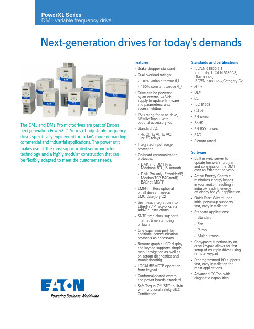
Next-generation drives for today’s demandsThe DM1 and DM1 Pro microdrives are part of Eaton’s next generation PowerXL E Series of adjustable frequency drives specifically engineered for today’s more demanding commercial and industrial applications. The power unit makes use of the most sophisticated semiconductor technology and a highly modular construction that can be flexibly adapted to meet the customer’s needs.Features•Brake chopper standard•Dual overload ratings:•110% variable torque (I L)•150% constant torque (I H)•Drive can be poweredby an external 24 Vdcsupply to update firmwareand parameters, andaccess fieldbus•IP20 rating for base drive,NEMA T Type 1 withoptional accessory kit•Standard I/O:•4x DI, 1x AI, 1x AO,2x FC relays•Integrated input surgeprotection•On-board communicationprotocols:•DM1 and DM1 Pro:Modbus T RTU, Bluetooth•DM1 Pro only: EtherNet/IP,Modbus TCP, BACnet/IP,BACnet MS/TP•EMI/RFI filters optionalon all drives—meetsEMC Category C2•Seamless integration intoEtherNet/IP networks viaAdd-On Instructions•SNTP time clock supportsinternet time stampingof faults•One expansion port foradditional communicationprotocols as necessary•Remote graphic LCD displayand keypad supports simplemenu navigation as well ason-screen diagnostics andtroubleshooting•LOCAL/REMOTE operationfrom keypad•Conformal-coated controland power boards standard•Safe Torque Off (STO) built-inwith functional safety SIL2CertificationStandards and certifications•IEC/EN 61800-5-1,Immunity: IEC/EN 61800-3,UL-61800-5,IEC/EN 61800-5-2,Category C2•cUL T•UL T•CE•IEC 61508•C-Tick•EN 62061•RoHS•EN ISO 13849-1•EAC•Plenum ratedSoftware•Built-in web server toupdate firmware, programand commission the DM1over an Ethernet network•Active Energy Control Tminimizes energy lossesin your motor, resulting inindustry-leading energyefficiency for your application•Quick Start Wizard uponinitial power-up supportsfast, easy installation•Standard applications:•Standard•Fan•Pump•Multipurpose•Copy/paste functionality ondrive keypad allows for fastsetup of multiple drives usingremote keypad•Preprogrammed I/O supportsfast, easy installation formost applications• Advanced PC Tool withdiagnostic capabilitiesEaton is a registered trademark.All other trademarks are property of their respective owners.Eaton10 Kent RoadMascot NSW 2020Australia /au© 2021 EatonAll Rights Reserved Printed in AustraliaPublication No. MP21-081 June 2021Catalog numbering systemTotal watts loss typical Typical efficiency 97.5% for three-phaseL up to 60 °C with derating, overload 1.1 x I L (1 min/10 min)I H : ambient temperature maximum 50 °C,MTBF300,000 hoursFollow us on social media to get the latest product and support information.。
Eaton 199037 产品说明书

Eaton 199037Eaton Moeller® series Rapid Link - Speed controllers, 8.5 A, 4 kW, Sensor input 4, Actuator output 2, 180/207 V DC, PROFINET, HAN Q4/2, STO (Safe Torque Off), with fanGeneral specificationsEaton Moeller® series Rapid Link Speed controller1990374015081970957195 mm 270 mm 220 mm 3.65 kg IEC/EN 61800-5-1 UL 61800-5-1 RoHS UL approval CEProduct NameCatalog NumberEANProduct Length/Depth Product Height Product Width Product Weight Certifications Catalog Notes 3 fixed speeds and 1 potentiometer speedcan be switched over from U/f to (vector) speed control Connection of supply voltage via adapter cable on round or flexible busbar junction Diagnostics and reset on the device and via PROFINETParameterization: KeypadParameterization: FieldbusParameterization: drivesConnectInternal and on heat sink, temperature-controlled Fan Parameterization: drivesConnect mobile (App)FanKey switch position HANDThermo-click with safe isolationInternal DC linkKey switch position AUTO2 Actuator outputsPC connectionSelector switch (Positions: REV - OFF - FWD)IGBT inverterTwo sensor inputs through M12 sockets (max. 150 mA) for quick stop and interlocked manual operationPTC thermistor monitoringKey switch position OFF/RESETControl unit3 fixed speedsSTO (Safe Torque Off)For actuation of motors with mechanical brake1 potentiometer speed IP65NEMA 121st and 2nd environments (according to EN 61800-3)IIISpeed controllerPROFINET IOC2, C3: depending on the motor cable length, the connected load, and ambient conditions. External radio interference suppression filters (optional) may be necessary.C1: for conducted emissions only2000 VAC voltagePhase-earthed AC supply systems are not permitted.Center-point earthed star network (TN-S network)Vertical15 g, Mechanical, According to IEC/EN 60068-2-27, 11 ms, Half-sinusoidal shock 11 ms, 1000 shocks per shaftResistance: 6 Hz, Amplitude 0.15 mmResistance: 10 - 150 Hz, Oscillation frequencyResistance: According to IEC/EN 60068-2-6Resistance: 57 Hz, Amplitude transition frequency on accelerationFeatures Fitted with:Functions Degree of protectionElectromagnetic compatibility Overvoltage categoryProduct categoryProtocolRadio interference classRated impulse withstand voltage (Uimp) System configuration typeMounting positionShock resistanceVibrationAbove 1000 m with 1 % performance reduction per 100 m Max. 2000 m-10 °C40 °C-40 °C70 °CIn accordance with IEC/EN 50178< 95 %, no condensation 0.8 - 8.5 A, motor, main circuit Adjustable, motor, main circuit< 10 ms, Off-delay< 10 ms, On-delay98 % (η)7.8 A3.5 mA120 %Maximum of one time every 60 seconds380 V480 V380 - 480 V (-10 %/+10 %, at 50/60 Hz)PM and LSPM motorsSynchronous reluctance motorsU/f controlBLDC motorsSensorless vector control (SLV)0 Hz500 HzAt 40 °CFor 60 s every 600 s12.7 AAltitudeAmbient operating temperature - min Ambient operating temperature - max Ambient storage temperature - min Ambient storage temperature - max Climatic proofing Current limitationDelay timeEfficiencyInput current ILN at 150% overload Leakage current at ground IPE - max Mains current distortionMains switch-on frequencyMains voltage - minMains voltage - maxMains voltage toleranceOperating modeOutput frequency - minOutput frequency - maxOverload currentOverload current IL at 150% overload45 Hz66 Hz4 kW480 V AC, 3-phase400 V AC, 3-phase0.1 Hz (Frequency resolution, setpoint value)200 %, IH, max. starting current (High Overload), For 2 seconds every 20 seconds, Power section50/60 Hz8 kHz, 4 - 32 kHz adjustable, fPWM, Power section, Main circuitAC voltagePhase-earthed AC supply systems are not permitted.Center-point earthed star network (TN-S network)5 HP≤ 0.6 A (max. 6 A for 120 ms), Actuator for external motor brake≤ 30 % (I/Ie)Adjustable to 100 % (I/Ie), DC - Main circuit280/207 V DC -15 % / +10 %, Actuator for external motor brake10 kAType 1 coordination via the power bus' feeder unit, Main circuit180/207 V DC (external brake 50/60 Hz)24 V DC (-15 %/+20 %, external via AS-Interface® plug)PROFINET, optionalPlug type: HAN Q4/2Number of slave addresses: 31 (AS-Interface®) Specification: S-7.4 (AS-Interface®)Max. total power consumption from AS-Interface® power supply unit (30 V): 250 mA C2 ≤ 5 m, maximum motor cable length C3 ≤ 25 m, maximum motor cable length C1 ≤ 1 m, maximum motor cable lengthMeets the product standard's requirements.Rated frequency - minRated frequency - maxRated operational power at 380/400 V, 50 Hz, 3-phase Rated operational voltageResolutionStarting current - maxSupply frequencySwitching frequencySystem configuration type Assigned motor power at 460/480 V, 60 Hz, 3-phase Braking currentBraking torqueBraking voltageRated conditional short-circuit current (Iq)Short-circuit protection (external output circuits) Rated control voltage (Uc)Communication interfaceConnectionInterfacesCable length10.2.2 Corrosion resistanceMeets the product standard's requirements.Meets the product standard's requirements.Meets the product standard's requirements.Meets the product standard's requirements.Does not apply, since the entire switchgear needs to be evaluated.Does not apply, since the entire switchgear needs to be evaluated.Meets the product standard's requirements.Does not apply, since the entire switchgear needs to be evaluated.Meets the product standard's requirements.Does not apply, since the entire switchgear needs to be evaluated.Does not apply, since the entire switchgear needs to be evaluated.Is the panel builder's responsibility.Is the panel builder's responsibility.Is the panel builder's responsibility.Is the panel builder's responsibility.Is the panel builder's responsibility.Rapid Link 5 - brochureDA-SW-drivesConnect - installation helpDA-SW-drivesConnectDA-SW-USB Driver DX-COM-STICK3-KITDA-SW-Driver DX-CBL-PC-3M0DA-SW-USB Driver PC Cable DX-CBL-PC-1M5DA-SW-drivesConnect - InstallationshilfeMaterial handling applications - airports, warehouses and intra-logisticseaton-bus-adapter-rapidlink-speed-controller-dimensions.epseaton-bus-adapter-rapidlink-speed-controller-dimensions-002.eps eaton-bus-adapter-rapidlink-speed-controller-dimensions-004.eps eaton-bus-adapter-rapidlink-speed-controller-dimensions-003.epsETN.RASP5-8421PNT-4120011S1.edzIL034093ZUrasp5_v40.stpramo5_v40.dwgGeneration change from RA-MO to RAMO 4.0Generation change RAMO4 to RAMO5Configuration to Rockwell PLC for Rapid LinkGeneration change from RA-SP to RASP 4.0Generation Change RASP4 to RASP5Generation Change RA-SP to RASP5DA-DC-00003964.pdfDA-DC-00004184.pdfDA-DC-00004613.pdfDA-DC-00004612.pdf10.2.3.1 Verification of thermal stability of enclosures10.2.3.2 Verification of resistance of insulating materials to normal heat10.2.3.3 Resist. of insul. mat. to abnormal heat/fire by internal elect. effects10.2.4 Resistance to ultra-violet (UV) radiation10.2.5 Lifting10.2.6 Mechanical impact10.2.7 Inscriptions10.3 Degree of protection of assemblies10.4 Clearances and creepage distances10.5 Protection against electric shock10.6 Incorporation of switching devices and components10.7 Internal electrical circuits and connections10.8 Connections for external conductors10.9.2 Power-frequency electric strength10.9.3 Impulse withstand voltage10.9.4 Testing of enclosures made of insulating material BrochureDisegnieCAD modelIstruzioni di installazione mCAD modelNote per l'applicazione Report di certificazioneEaton Corporation plc Eaton House30 Pembroke Road Dublin 4, Ireland © 2023 Eaton. Tutti i diritti riservati. Eaton is a registered trademark.All other trademarks areproperty of their respectiveowners./socialmediaThe panel builder is responsible for the temperature rise calculation. Eaton will provide heat dissipation data for the devices.Is the panel builder's responsibility. The specifications for the switchgear must be observed.Is the panel builder's responsibility. The specifications for the switchgear must be observed.The device meets the requirements, provided the information in the instruction leaflet (IL) is observed.10.10 Temperature rise10.11 Short-circuit rating10.12 Electromagnetic compatibility10.13 Mechanical function。
伊顿离合器安装手册(中英版)解读

离轴承架能够进入离合器盖总成以及分离指支撑卡环能够滑到离 合器分离轴承的槽口中。
14
14
1、Install transmission with “Quick-connect Bearing” 安装变速箱 -带可快速拆卸式轴承
• 1.14. To verify the release yoke has swung into position, attempt to move the end of the Release Yoke. (See picture) There should be approximately 9.0mm [.35”] of fore-aft movement. If there is more than that, repeat the procedure. • 1.14. 通过拨动分离拨叉的端部,检查分离拨叉端部前后移动量应 接近9毫米。如果此值超出,应重新安装变速器。 • 在确认安全的情况(未安装助力泵前),可将手从离合器观察窗口 伸入,感觉辫子的锁紧力,如果锁紧力很大,可能出现了分离轴承未完 全到位的情况,应重新安装变速箱
5
5
1、I-Instruction of “Clutch Assembly” 离合器总成安装指导 - 带非快速拆卸式轴承
• 1.5. Install disc onto aligning tool. • Important: Make sure the side marked “Flywheel Side” faces the flywheel. • 1.5. 将导向花键轴穿过从动盘。 • 重要:确保从动盘上标有“Flywheel Side”面朝向飞轮。
15
15
Removal and Installation of Clutch in Field 现场拆卸和安装离合器
盘式制动器手册

DBB 8100警告负责安装、操作和维修本产品的人员都应阅读本手册。
若不了解相关内容,错误的安装、操作或维修可能会导致人身伤害或设备损坏。
Airflex ® DBB 型盘式刹车 安装、操作和维修说明书请认准使用Airflex ®替换零件伊顿集团Airflex ®分公司推荐使用真正的Airflex ®替换零件。
使用非Airflex ®替换零件会使您的产品性能下降,并且会使伊顿公司的质量保证失效。
欲获得最佳性能,请致电Airflex ®公司:美国和加拿大地区:1-800-AIRFLEX (247-3539) 美国和加拿大以外地区:(216)281-2211 网址:中国地区请致电:(21) 50484811或 传真 (21)504849111990年10月(修订:2001年8月)204045!!目录1.0 前言 (4)1.1 说明 (4)1.2 工作原理 (4)2.0 安装 (4)2.1 准备 (4)2.2 安装 (5)2.3 供气系统 (6)3.0 操作 (7)3.1 压力和速度极限 (7)3.1 初始操作 (7)3.1 定期维护保养 (7)4.0 维修 (8)4.1 磨损极限 (8)4.2 摩擦片的替换 (8)4.3 气路的维修 (11)4.4 汽缸密封的替换 (12)4.5 弹簧的替换 (12)5.0 订购信息和技术支持 (14)6.0 零件清单……………………………………………………………………………………………15-19图1图1续单磨擦盘双磨擦盘双磨擦盘单磨擦盘图1续项目名称项目名称项目名称2 安装法兰23 Polypak密封件41 变径三通6 螺栓27 间隔管42 软管组件7 磨擦盘组件28 齿轮43 管接头12 夹管29 磨损环44 流量控制阀14 压紧盘31 中间盘45 45°弯头16 弹簧套34 释放弹簧46 十字管17 平垫圈35 垫圈47 管变径接头18 自锁螺母36 六角头螺钉48 软管组件19 气缸37 齿环52 内弹簧20 六角头螺钉38 管接头53 弹簧座21 Polypak密封件39 弯管56 六角头螺钉1.0 前言必须认真阅读并理解本手册中带有危险警告标志的内容,以避免造成人员伤害或设备损坏。
Eaton产品参考手册说明书

AE712018-1
Fuel Manifold
Honeywell 131-12
AE712018-3
Fuel Manifold
Honeywell 131-13
40338
Flex-Slide Connection
F50
63 Eaton 64 Eaton 65 Eaton 66 Eaton 67 Eaton 68 Eaton 69 Eaton 70 Eaton 71 Eaton 72 Eaton 73 Eaton 74 Eaton 75 Eaton 76 Eaton 77 Eaton 78 Eaton 79 Eaton 80 Eaton 81 Eaton 82 Eaton 83 Eaton 84 Eaton 85 Eaton 86 Eaton 87 Eaton 88 Eaton 89 Eaton 90 Eaton 91 Eaton 92 Eaton 93 Eaton 94 Eaton 95 Eaton 96 Eaton 97 Eaton 98 Eaton 99 Eaton 100 Eaton 101 Eaton 102 Eaton 103 Eaton 104 Eaton 105 Eaton 106 Eaton 107 Eaton 108 Eaton 109 Eaton 110 Eaton 111 Eaton 112 Eaton 113 Eaton 114 Eaton 115 Eaton 116 Eaton 117 Eaton 118 Eaton 119 Eaton 120 Eaton 121 Eaton 122 Eaton 123 Eaton 124 Eaton 125 Eaton 126 Eaton 127 Eaton 128 Eaton 129 Eaton
40742-250F 41557-200 41590-200 41739-300 42193-100 42272-150 42272-200 42563-150 42755-125 42756-200 42757-200 42759-150 42761-150 42762-150 42779-200 42854-200 42920-200 43129-200 6355530-1 6355530-40 65004-200 65005-250 65360 65435 65603 65618 6636103003-005 6915060-2 CN01213-001 FD01230-001 GA01210-003 GA01212-003 GA01214-005 GA01216-007 GA01218-005 GA01220-001 GA01222-001 GA01224-003 GA01226-007 GA01110-503 GA01212-004 GA01260-003 GA01264-007 GA01266-007 GA01268-005 GA01270-001 GA01272-001 GA01276-007 GA01110-504 GA0236160101-1 GA0236160101-3 GA0236160102-5 GA0236160102-7 GA0236160103-1 GA0221210204-1 GA0236160106-1 GA0221210203-1 GA0236160206-1 GA0236160211-1 GA0236160213-1 GA0236160214-3 GA0236160218-1 GA0236160219-1 GA0236160001-1 GA0236160002-1 GA0236160003-1 GA0236160003-2
美国Eaton公司重制篇:高扭力重制刹车舱说明书
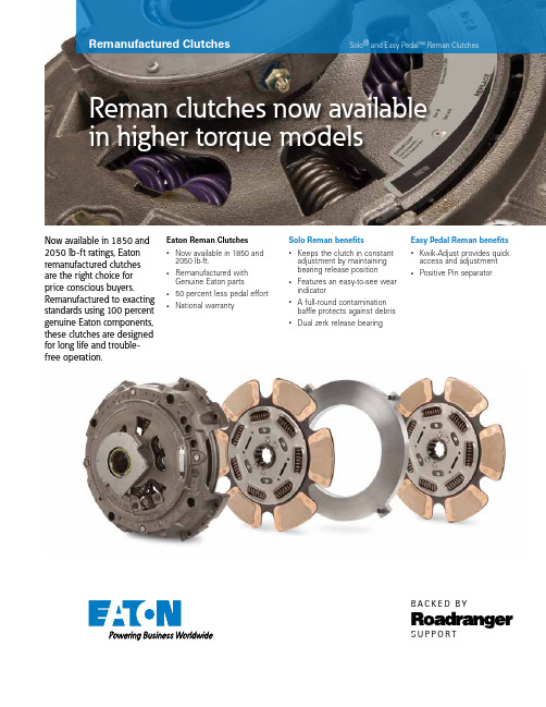
Remanufactured Clutchesin higher torque modelsSolo® and Easy Pedal™ Reman ClutchesNow available in 1850 and 2050 lb-ft ratings, Eaton remanufactured clutches are the right choice for price conscious buyers. Remanufactured to exacting standards using 100 percent genuine Eaton components, these clutches are designed for long life and trouble-free operation.Solo Reman benefits• Keeps the clutch in constantadjustment by maintainingbearing release position• Features an easy-to-see wearindicator• A full-round contaminationbaffle protects against debris• Dual zerk release bearingS U P P O R TB AC K ED B YEaton Reman Clutches• Now available in 1850 and2050 lb-ft.• Remanufactured withGenuine Eaton parts•50 percent less pedal effort•National warrantyEasy Pedal Reman benefits•Kwik-Adjust provides quickaccess and adjustment•Positive Pin separatorRemanufactured ClutchesS U P P O R TB AC K ED B YFor spec’ing or service assistance, call 1-800-826-HELP (4357) or visit /roadranger . In Mexico, call 001-800-826-4357.Roadranger: Eaton and trusted partnersproviding the best products and services in the industry, ensuring more time on the road.EatonVehicle Group13100 E. Michigan Ave.Galesburg, MI 49053 USA 800-826-HELP (4357)/roadranger © 2016 EatonAll Rights Reserved. Printed in USA.CLSL1304 0916Note: Features and specifications listed in this document are subject to change without notice and represent the maximum capa-bilities of the software and products with all options installed. Although every attempt has been made to ensure the accuracy of information contained within, Eaton makes no representation about the completeness, correctness or accuracy and assumes no responsibility for any errors or omissions. Features and functionality may vary depending on selected options.Eaton, Fuller, Roadranger, Solo, UltraShift and Fuller Advantage are registered trademarks of Eaton. All trademarks, logos and copyrights are those of their respective owners.† New part numbers September 2016。
Eaton EAD40CH10C 产品说明书

Eaton EAD40CH10CEaton Moeller series xPole - eRB6/M RCBO - residual-current circuit breaker with overcurrent protection. Electronic RCD/MCB, 40A, 10mA, MCB char. curve: C, 1p, RCCB trip char.: ACGeneral specificationsEaton Moeller series xPole - eRB6/M RCBO - residual-current circuit breaker with overcurrent protectionEAD40CH10C 9008790342516216 mm 72 mm 17.5 mm 0.18 kg CE Marked RoHS conformCE eRB6-40/1/C/001Product NameCatalog Number EANProduct Length/Depth Product Height Product Width Product Weight Compliances Certifications Model Code40 AIs the panel builder's responsibility. The specifications for the switchgear must be observed.Meets the product standard's requirements.Is the panel builder's responsibility. The specifications for the switchgear must be observed.3Does not apply, since the entire switchgear needs to be evaluated.Meets the product standard's requirements.0 kA50 HzIs the panel builder's responsibility.10.01 A40 °C0 W69.5 mm1 mm²03_eRB_220620DA-DC-03_eRBeaton-xpole-combined-mcb-rcd-device-rcbo-packaging-manual-multilingual.pdfMA120500735.pdfIL019095ZUeaton-xpole-erb6-rcbo-catalog-ca019049en-en-us.pdfeaton-xpole-erb6/m-dimensions.jpgeaton-xpole-erb6-au-rcbo-catalog-ca019052en-en-us.pdf eaton-xpole-erb6/m-wiring-diagram.jpgRated operational current for specified heat dissipation (In) 10.11 Short-circuit rating10.4 Clearances and creepage distances10.12 Electromagnetic compatibilityCurrent limiting class10.2.5 Lifting10.2.3.1 Verification of thermal stability of enclosures Rated short-circuit breaking capacity (EN 60947-2) Frequency rating10.8 Connections for external conductorsNumber of poles (total)Fault current ratingAmbient operating temperature - maxHeat dissipation per pole, current-dependentBuilt-in depthConnectable conductor cross section (solid-core) - min 10.9.3 Impulse withstand voltage Certifikater Installationsvejledning Kataloger LedningsdiagrammerIs the panel builder's responsibility.Number of polesSingle-poleAmbient operating temperature - min-25 °C10.6 Incorporation of switching devices and componentsDoes not apply, since the entire switchgear needs to be evaluated.10.5 Protection against electric shockDoes not apply, since the entire switchgear needs to be evaluated.Equipment heat dissipation, current-dependent14.7 W10.13 Mechanical functionThe device meets the requirements, provided the information in the instruction leaflet (IL) is observed.10.2.6 Mechanical impactDoes not apply, since the entire switchgear needs to be evaluated.10.9.4 Testing of enclosures made of insulating materialIs the panel builder's responsibility.Static heat dissipation, non-current-dependent0 WApplicationSwitchgear for residential and commercial applications10.3 Degree of protection of assembliesDoes not apply, since the entire switchgear needs to be evaluated.Voltage typeACNumber of poles (protected)1Leakage current typeACRated short-circuit breaking capacity (EN 61009-1)6 kAOperating ambient temperature - min-25 °CHeat dissipation capacity0 WRelease characteristicCWidth in number of modular spacings1Power loss14.7 W10.2.3.2 Verification of resistance of insulating materials to normal heatMeets the product standard's requirements.10.2.3.3 Resist. of insul. mat. to abnormal heat/fire by internal elect. effectsMeets the product standard's requirements.Rated short-circuit breaking capacity (EN 61009)6 kAOperating ambient temperature - max40 °CVoltage rating240 V - 240 V10.9.2 Power-frequency electric strengthIs the panel builder's responsibility.Connectable conductor cross section (solid-core) - max25 mm²Degree of protectionIP20Overvoltage categoryIIIPollution degree210.7 Internal electrical circuits and connectionsIs the panel builder's responsibility.Connectable conductor cross section (multi-wired) - min1 mm²Rated impulse withstand voltage (Uimp)4 kV10.10 Temperature riseThe panel builder is responsible for the temperature risecalculation. Eaton will provide heat dissipation data for the devices.Basic functionCombined RCD/MCB devicesRated current40 AConnectable conductor cross section (multi-wired) - max 25 mm²TypeRCBO10.2.2 Corrosion resistanceMeets the product standard's requirements.Surge current capacity0.25 kA10.2.4 Resistance to ultra-violet (UV) radiationMeets the product standard's requirements.10.2.7 InscriptionsMeets the product standard's requirements.Rated short-circuit breaking capacity (IEC 60947-2)0 kADisconnection characteristicUndelayedProduct applicationSwitchgear for residential and commercial applicationsRated operational voltage (Ue) - max240 VRated insulation voltage (Ui)500 VEaton Corporation plc Eaton House30 Pembroke Road Dublin 4, Ireland © 2023 Eaton. Alle rettigheder forbeholdes. Eaton is a registered trademark.All other trademarks areproperty of their respectiveowners./socialmedia。
Eaton Heavy-Duty Automated Transmissions产品介绍说明书

S U P P O R TB AC K ED BYFeatures•T wo hands on steering wheel• Proper gear for every situation •Starter inhibitFeatures•Automated shifting• Driver control• Engine brake compatibilityAdvantages•Less driver distractions • Drivers are more aware of surroundings• Eliminates shifting errors •Starter does not engage until transmission verifies neutralAdvantages•Fast, consistent and smooth shifts with intelligent gear selection• Compatible with all cruise control systems• Reduced drivetrain and driveline abuse as well as reduced starts in improper gear•“Manual” mode allows for complete driver input •“Manual” and “Low” mode optimizes engine braking for controlled vehicle decelerationFeatures•Ease of operation•Maintenance-free clutch (UltraShift only)• Extended protection plansFeatures• Eaton ® Fuller ® basetransmission• Integrated diagnostics• Roadranger Field SupportAdvantages•Less driver skill required to operate• Increased driver retention rate – "Street-to-Seat”• Shift point calibrations allow for optimal fuel economy savings•No lubrication required on DM clutch• Alerts driver of abuse situations, preventing catastrophic failures • Float-shifting of transmission reduces wear to clutch facing material•Tiered protection plans with varying coverage options up to 2 years/200,000 milesAdvantages•Based on robust RT seriesmanual transmission allowing for simple removal and replacement of electronics• Serviceable at any certified OEM dealership•Simple fault isolation procedures • Continuous diagnostic evaluation – alerts driver to a problem•Access to the industry’s largest and most comprehensive support network including Canada and MexicoSAFETY PERFORMANCE OPERA TING COSTSSERVICEABILITYS U P P O R TB AC K ED B YNote: Features and specifications listed in this document are subject to change without notice and represent the maximum capa-bilities of the software and products with all options installed. Although every attempt has been made to ensure the accuracy of information contained within, Eaton makes no representation about the completeness, correctness or accuracy and assumes no responsibility for any errors or omissions. Features and functionality may vary depending on selected options.Eaton, Fuller, Roadranger, Solo and UltraShift are registered trademarks of Eaton. All trade-marks, logos and copyrights are those of their respective owners.For spec’ing or service assistance, call 1-800-826-HELP (4357) or visit /roadranger . In Mexico, call 001-800-826-4357.Roadranger: Eaton and trusted partnersproviding the best products and services in the industry, ensuring more time on the road.EatonVehicle Group P .O. Box 4013Kalamazoo, MI 49003 USA 800-826-HELP (4357)/roadranger © 2013 EatonAll Rights Reserved. Printed in USA.RWSL0020 1013How does operating an Eaton Automa ted T ra nsmission a ffect fuel economy?Constant communicationbetween the transmission and engine, coupled with shift calibra-tions matched to each engine’s operating characteristics ensure fuel economy is optimized per specific customer application.Does operating an Eaton Automa ted T ra nsmissionreduce operating/maintenance costs?Intelligent shift controls ensure that the right gear is selected at the right time, with no "missed" shifts. This provides smoother shifting and lessens the likelihood of ”shock-loads“ to the driveline or drivetrain. In addition, the transmission has a 500,000 mile lube change interval while the fully automated DM Clutch requires no maintenance(AutoShift clutches still require lubrication). With this technology, clutch abuse from less advanced drivers in most situations is reduced. If clutch abuse occurs, the transmission will alert the driver and will be placed in a clutch protection mode.Furthermore, the clutch in each model is used primarily forlaunching and stopping of vehicle motion. The transmission is float-shifted between gears, allowing the clutch to remain engaged, therefore reducing wear on the clutch facing material.What has Eaton done to improve the reliability of its automated transmission?Eaton released its firstautomated transmission, over 25 years ago. Since then, significant improvements have been made to component parts such as the T ransmission ECU, XY Shifter, and the DM Clutch module. T ransmission software has also been updated regularly to accom-modate changes in engine operating ranges, further optimize shift points, andenhance operating characteris-tics. Reliability has been thefocus of these components and software improvements.Is serviceability impacted with an Eaton Automated T ransmission?Unlike most other automated transmissions in the industry, Eaton‘s automated transmissions are based on the robust RT Series manual transmissions. With this in mind, EatonAutoShift and UltraShiftAutomated T ransmissions are fully serviceable by all trained OEM dealerships. Most OEM dealerships have parts for Eaton AutoShift and UltraShiftAutomated T ransmissions readily available to further reduce downtime.What is slow speedmaneuverability like with an Eaton Automated T ransmission?Slow speed maneuverability is not compromised on Eaton Automated T ransmissions. On AutoShift models, drivers will manipulate the clutch and brake pedals as if it were a manual transmission. On UltraShift models, the driver will use the throttle to launch the vehicle and use the brake pedal to control vehicle speed. With proper training, operation is equally as effective as a manual transmis-sion.Does the driver still maintain control with an Eaton Automa ted T ra nsmission?Y es, in “manual” mode, the driver will have full shift control over the transmission, provided the conditions are correct for ashift. This prevents the engine from being stalled on upshifts or over-sped on downshifts. Inaddition, the driver can use “low” mode to hold the transmission in the selected gear. “Low” mode can also be effective whendescending a grade, as it allows for maximum engine braking.How is safety impacted with an Eaton Automated T ransmission?With an Eaton AutomatedT ransmission, safety is enhanced as the driver does not have the distraction of using the clutch or shifting a lever. Additionally, the transmission is in constantcommunication with the vehicle‘s ABS system and will not attempt a shift during an ”ABS event.“ This ensures that shifting errors are eliminated, reducing both equip-ment failures and driver fatigue. Lastly, the transmission will always verify neutral before allowing the engine to crank preventing a start-up in gear condition when unwanted andundesired.。