安全阀说明书SF-A42C
安全阀说明书
第 1 页共 15 页安全阀使用说明书目录一、用途二、主要零件的作用及结构特点三、安装1.安全阀安装2.排汽管的安装3、输水管的安装四、现场调试1.调试前准备2.新供货的阀门校验性试验3.检修后的阀门调整方法4.上、下调整环、调整套位置表示方法五、解体与装配1.局部解体2.局部解体后装配3.总解体4.总解体后装配六、研磨1.研磨工具的准备2.研磨胎具的制作3.研磨七、安全阀主要零件维护及更换标准八、订货须知一、用途安全阀用于蒸汽温度≤580℃,整定压力≤14MPa的锅炉,压力容器。
以防止蒸汽压力超过规定值,确保设备安全运行,整套阀门是按照日本冈野阀门株式会社全量型安全阀技术制造。
二、主要零件的作用及结构特点安全阀结构如图所示。
安全阀阀座设计成拉伐尔喷嘴形状,阀座内径大于等于1.15倍喉部直径,安全阀达到全开位置时,阀座口处流通面积大于1.05倍喉部面积。
根据拉伐尔喷嘴介质流动原理阀座出口介质流速达到音速,使安全阀排放系数大于0.75。
阀座突出在阀体内,避免阀体热应力对阀座密封面的影响,密封件采用了热阀瓣,并与阀瓣套筒用阀瓣螺母固定在一起,避免阀瓣套筒和阀瓣的热应力对阀瓣密封面的影响,提高了密封性。
热阀瓣用韧性好、强度高、抗冲刷、耐高温的材料制作,热阀瓣如图 -1所示,其优点是当密封面有少量蒸汽漏泄时,漏出的蒸汽降压同时降温。
热阀瓣舌头形状下部温度低于上部温度,舌头部位产生弯曲,后部就翘起,舌头部位紧接触于阀座上,增加了密封比压,提高密封能力。
当介质压力升高,介质作用力与弹簧力相平衡时,漏量无法避免。
漏量增加到一定程度时下调整环上部与热阀瓣下部形成的压力区域内的内压力将随着漏量增加而迅速增加,改变蒸汽对阀瓣的作用力,而使介质有足够的力,克服弹簧力,使阀门启跳,调整下调整环的位置高低,改变压力区域内压力,能得到满意的启跳压力,调整上调整环位置的高低,改变流体对阀瓣的反作用力,能影响阀门启跳高度和影响回座压力,当调整环得不到满意的回座压力时,可调整调整套位置,改变阀瓣背压,就可得到满意的回座压力。
氨用安全阀说明书
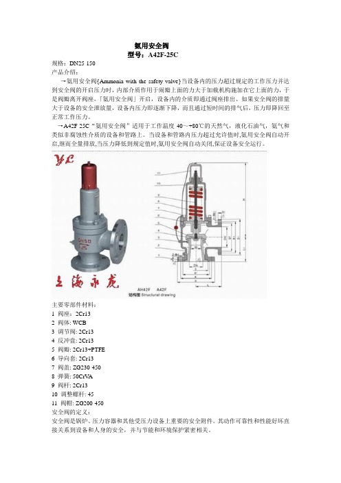
氨用安全阀
型号:A42F-25C
规格:DN25-150
产品介绍:
→氨用安全阀{Ammonia with the safety valve}当设备内的压力超过规定的工作压力并达到安全阀的开启压力时,内部介质作用于闹瓣上面的力大于加载机构施加在它上面的力,于是阀瓣离开阀座,「氨用安全阀」开启,设备内的介质即通过阀座排出、如果安全阀的排量大于设备的安全泄放量,设备内压力即逐渐下降,而且通过短时间的排气后,压力即降回至正常工作压力。
→A42F-25C“氨用安全阀”适用于工作温度-40~+80℃的天然气,液化石油气,氨气和类似非腐蚀性介质的设备和管路上。
当设备和管路内压力超过允许值时,氨用安全阀自动开启,继而全量排放,当压力降低到规定值时,氨用安全阀自动关闭,保证设备安全运行。
主要零部件材料:
1 阀座:2Cr13
2 阀体: WCB
3 调节阀: 2Cr13
4 反冲盘: 2Cr13
5 阀瓣: 2Cr13+PTFE
6 导向套: 2Cr13
7 阀盖: ZG230-450
8 弹簧: 50CrV A
9 阀杆: 2Cr13
10 调整螺杆: 45
11 阀帽: ZG200-450
安全阀的定义:
安全阀是锅炉、压力容器和其他受压力设备上重要的安全附件。
其动作可靠性和性能好坏直接关系到设备和人身的安全,并与节能和环境保护紧密相关。
美标安全阀-思氟阀门

美标安全阀介绍:安全阀的品种已发展到百余个系列,千余个规格,产品广泛应用于锅炉、石化、电站以及国防工业。
并为国内第一座核电站秦山核电站研制成功了第一批核级安全阀。
好施牌安全阀主要产品系列分别荣获机械部信得过产品,上海市优质产品称号,国家银质奖。
好施牌安全阀是受压设备、容器或管路上的最佳超压保护装置。
当设备压力升高达到预定值时,安全阀自动开启,继而全量排放,防止设备压力继续升高;当压力降低到规定值时,安全阀及时自动关闭。
好施牌安全阀是选用者为保护工程设备安全运行的最理想的,最科学的明智选择。
主要连接尺寸:型号公称流道直径(mm)连接尺寸(通径*压力级)结构长度阀体材料适用范围备注压力(Mpa)通径(mm)进口出口L(mm)L1(mm)介质温度℃SFA-22C150C11501/2″12R? 1/2″Rc 1/2″365635气体≤300SFA-41C150C11501/2″101/2″×1503/4″×150909020液体,气体≤200SFA-21C300C13001/2″7R? 1/2″Rc 1″4584WCB 液体,气体≤250SFA-21C300P13001/2″7R? 1/2″Rc 1″4584ZG1Cr18Ni9Ti硝酸类≤200 SFA-22C300T3001/2″61/2″NPT——00H62R22≤55SFA-41BC300C13001/2″61/2″×3001/2″×150909020液体,气体≤300SFA-41C300C13001/2″61/2″×3001/2″×150909020液体,气体≤200SFA-41C300C23001/2″101/2″×3001/2″×150909020液体,气体≤200SFA-42C1500P115001/2″31/2″×15001/2″×150140145CF8硝酸类气体≤200SFA-21C150C11503/4″6Z3/4″Z1″448535液体,气体≤300SFA-22C150C21503/4″10ZG3/4″ZG3/4″958820气体≤300 SFA-2C150T11503/4″12R3/4″Rc 3/4″2832H62气体≤300SFA-41BC150C11503/4″163/4″×1501×150100100WCB 气体,液体≤300SFA-41BC150C21503/4″123/4″×1503/4″×1509595WCB 气体,液体≤300SFA-42C150C31503/4″103/4″×1503/4″×150959520气体≤300 SFA-42C150C41503/4″103/4″×1501″×150100110WCB气体≤300 SFA-42C150C51503/4″103/4″×1501″×150969225气体≤300 SFA-42C150P61503/4″103/4″×1501″×1509567OCr18Ni9Ti硝酸类气≤200体SFA-42C150R51503/4″103/4″×1501″×1509692OCr18Ni12Mo2Ti 醋酸类气体≤200SFA-11C300C23003/4″10Rc 3/4″Rc 16762WCB 液体,气体≤250SFA-21C300C13003/4″0Z3/4″Z1459020气体,液体≤300SFA-41BC300C13003/4″163/4″×3001″×150100100ZG230-450气体,液体≤300SFA-41BC300R23003/4″103/4″×3001″×300100100CF8M醋酸类≤200 SFA-42C300C33003/4″103/4″×3003/4″×150959520气体≤300 SFA-42C300C43003/4″103/4″×3001″×150969235醋酸类≤300 SFA-41BC600R26003/4″103/4″×6001″×300105110CF8M醋酸类≤200 SFA-41C1500P215003/4″103/4″×15001″×1500120137OCr18Ni9Ti气体≤200SFA-42C1500P115003/4″103/4″×15001″×9001201361Cr18Ni9Ti 硝酸类气体≤200SFA-47C2500P125003/4″103/4″×25001″×300120120OCr18Ni9Ti硝酸类≤350 SFA-42BC150C11501″161″×1501″×150100100WCB液体≤300SFA-41C150C11501″161″×1501″×150100100ZG230-450气体,液体≤300SFA-41C150C21501″101″×1502″×150115105ZG230-450气体,液体≤300SFA-41C150C31501″201″×1502″×150********液体,气体≤300SFA-41C150P11501″161″×1501″×150100100ZG1Cr18Ni9Ti硝酸类≤200 SFA-41C150R21501″101″×1502″×150115105ZGOCr18Ni12Mo2Ti醋酸类≤200 SFA-42C150C11501″131″×1502″×150115105ZG230-450气体≤300 SFA-42C150C41501″101″×1502″×150119105WCB气体≤300 SFA-42C150C51501″101″×1502″×150115105WCB气体≤300 SFA-42C150P11501″131″×1502″×150115105CF8气体≤200 SFA-42C150P61501″161″×1502″×150115105CF8气体≤200 SFA-42C150R51501″101″×1502″×150115105ZGOCr18Ni12Mo2Ti气体≤300 SFA-42C150R61501″161″×1502″×150115105ZGOCr18Ni12Mo2Ti气体≤200 SFA-42SC150C11501″131″×1502″×150115105WCB气体≤350 SFA-42SC150C51501″101″×1502″×150115105WCB气体≤300SFA-44C150C21501″201″×1501 1/2″×1509510520气体≤300SFA-44C150C41501″101″×1502″×150119105WCB气体≤300 SFA-48C150C11501″131″×1502″×150115105ZG230-450蒸气≤350SFA-11C300C13001″13Rc 1″Rc 1 1/2″6762WCB 液体,气体≤250SFA-22C300T3001″181″NPT——00H62R22≤55SFA-41BC300C23001″161″×3001″×150100100ZG230-450气体,液体≤300SFA-41BC300C33001″161″×3002″×150114105ZG230-450气体,液体≤300SFA-41BC300R23001″161″×3001″×150100100CF8M醋酸类≤200SFA-41C300C23001″161″×3001″×150100100ZG230-450气体,液体≤300SFA-41C300C43001″101″×3002″×150115105ZG230-450气体,液体≤300SFA-41C300C53001″161″×3002″×300115105ZG230-450气体,液体≤300SFA-41C300C63001″101″×3002″×300150105ZG230-450气体,液体≤300SFA-41C300R33001″10115105≤300 SFA-42C300C33001″101″×3002″×300115105ZG230-450气体≤300 SFA-42C300C43001″101″×3002″×300150105ZG230-450气体≤300 SFA-42C300C53001″101″×3002″×150115105WCB气体≤300 SFA-42C300C83001″131″×3002″×150115105WCB气体≤300SFA-42C300R33001″101″×3002″×150115105ZGOCr18Ni12Mo2Ti 醋酸类气体≤200SFA-42C300R83001″131″×3002″×150115105ZGOCr18Ni12Mo2Ti 醋酸类气体≤200SFA-42SC300C53001″101″×3002″×150115105WCB气体≤400 SFA-42SC300C83001″181″×3002″×150115105WCB气体≤400 SFA-44C300C13001″161″×3002″×150121105ZG230-450气体≤300 SFA-44C300C23001″161″×3002″×150114105ZG230-450气体≤300 SFA-44C300C53001″101″×3002″×150115105ZG230-450气体≤300 SFA-44C300C73001″121″×3002″×150119114WCB气体≤300 SFA-44SC300C23001″161″×3002″×150114105ZG230-450气体≤350 SFA-48C300C53001″101″×3002″×150115105WCB蒸气≤300SFA-41C600C16001″161″×6001 1/2″×600150150WCB液体,气体≤300SFA-41C600R16001″161″×6001 1/2″×600150150ZGOCr18Ni12Mo2Ti醋酸类≤200SFA-42C600C26001″131″×6002″×150115105WCB气体≤300 SFA-42C600C36001″101″×6002″×150115105WCB气体≤300SFA-42SC600C26001″131″×6002″×150115105WCB气体≤400 SFA-42SC600C36001″101″×6002″×150115105WCB气体≤350 SFA-44SC600I16001″161″×6002″×150114105ZG20CrMo气体≤510 SFA-48C600C26001″131″×6002″×150115105WCB蒸气≤350 SFA-48C600C36001″101″×6002″×150115105WCB蒸气≤350SFA-21C1500C115001″8G1″G1″458535液体,气体≤300SFA-41BC1500C115001″161″×15001 1/2″×150125125ZG230-450气体,液体≤300SFA-28C150C11501″21R1″RC???? 1 ″5508520蒸气≤350SFA-22C150C115011/4″21R1 1/4″RC 1 1/4″5510020气体≤300SFA-44C300C130011/4″201 1/4″×3001 1/4″×1509510520气体≤300SFA-22C150C115011/2″26R1 1/2″RC???? 1?1/2″6511020气体≤300SFA-22C150C215011/2″32R1 1/2″RC???? 26511020气体≤300SFA-28C150C115011/2″26R1 1/2″RC 1 1/2″6511020蒸气≤350SFA-41C150C215011/2″331 1/2″×1502? 1/2″×150121124WCB液体,气体≤300SFA-42C150C115011/2″251 1/2″×1502? 1/2″×150121124ZG230-450气体≤300SFA-42C150C215011/2″201 1/2″×1502? 1/2″×150121124ZG230-450气体≤300SFA-42C150C315011/2″251 1/2″×1503″×150124130ZG130-450气体≤300SFA-42C150C415011/2″171 1/2″×1502″×150121124ZG230-450气体≤300SFA-42C150P115011/2″251 1/2″×1502? 1/2″×150121124ZG1Cr18Ni9Ti硝酸类气体≤200SFA-42C150R315011/2″251 1/2″×1503″×150124130CF8M醋酸类气体≤200SFA-42SC150C415011/2″171 1/2″×1502″×150121124WCB气体≤450SFA-44C150C115011/2″251 1/2″×1502″×150100110WCB气体≤300SFA-44C150C515011/2″201 1/2″×1502″×150100110WCB气体≤300SFA-44C150C715011/2″261 1/2″×1503″×150129130WCB气体≤300SFA-44C150C815011/2″161 1/2″×1502″×150124125WCB气体≤300SFA-48C150C415011/2″171 1/2″×1502″×150121124ZG230-450蒸气≤350SFA-41BC300C130011/2″321 1/2″×3002″×150110115ZG230-450气体,液体≤300SFA-42C300C130011/2″251 1/2″×3002? 1/2″×150121124ZG230-450气体≤300SFA-42C300C1030011/2″261 1/2″×3003″×150129138WCB气体≤300SFA-42C300C1130011/2″201 1/2″×3002? 1/2″×150124121WCB气体≤300SFA-42C300C1230011/2″161 1/2″×3002″×150124121WCB气体≤300SFA-42C300C1330011/2″261 1/2″×3003″×150124130WCB气体≤300SFA-42C300C1430011/2″171 1/2″×3002″×150152124WCB气体≤300SFA-42C300C230011/2″171 1/2″×3002″×150152124ZG230-450气体≤300SFA-42C300C330011/2″221 1/2″×3002? 1/2″×150152124ZG230-450气体≤300SFA-42C300R230011/2″171 1/2″×3002″×150152124ZGOCr18Ni12Mo2Ti气体≤200SFA-42C300R330011/2″221 1/2″×3002? 1/2″×150152124ZGOCr18Ni12Mo2Ti气体≤200SFA-42SC300C1130011/2″201 1/2″×3002? 1/2″×150124121WCB气体≤400SFA-42SC300C1230011/2″161 1/2″×3002″×150124121WCB气体≤400SFA-44C300C430011/2″201 1/2″×3002″×150121124ZG230-450气体≤300SFA-44C300C830011/2″161 1/2″×3002″×150136124WCB气体≤300SFA-44C300C930011/2″161 1/2″×3002″×150124133WCB气体≤300SFA-48C300C1130011/2″201 1/2″×3002? 1/2″×150124121WCB蒸气≤300SFA-41C600P160011/2″251 1/2″×6002 1/2″×1501471621Cr18Ni9Ti硝酸类≤200SFA-41C600P260011/2″251 1/2″×6002″×1501471621Cr18Ni9Ti硝酸类≤200SFA-42C600C160011/2″251 1/2″×6002 1/2″×150152124ZG230-450气体≤300SFA-42C600C460011/2″161 1/2″×6002″×150152124ZG230-450气体≤300SFA-42SC600C160011/2″251 1/2″×6002 1/2″×150152124ZG230-450气体≤450SFA-44C600C660011/2″161 1/2″×1502″×150129125WCB气体≤300SFA-44C600C760011/2″221 1/2″×6002″×150152124WCB气体≤300SFA-48C600C360011/2″201 1/2″×6002 1/2″×150152124ZG230-450蒸气≤300SFA-48SC600C260011/2″201 1/2″×6002 1/2″×150118127WCB蒸气≤450SFA-48SC600C560011/2″161 1/2″×6002″×150152124ZG230-450蒸气≤450SFA-41C1500C3150011/2″181 1/2″×15002″×150140105ZG230-450气体,液体≤300SFA-41C1500P2150011/2″131 1/2″×15001 1/2″×300150194ZG1Cr18Ni9Ti硝酸类≤200SFA-42C1500C1150011/2″101 1/2″×15002″×300140105ZG230-450气体≤300SFA-42C1500C3150011/2″211 1/2″×15002? 1/2″×300152124WCB气体≤300SFA-48SC1500C1150011/2″181 1/2″×15002? 1/2″×1500146170WCB蒸气≤450SFA-48SC1500C2150011/2″221 1/2″×15003″×300169220ZG230-450蒸气≤450SFA-48SC2500C1250011/2″161 1/2″×25002? 1/2″×1500165140ZG25Ⅱ蒸气≤450SFA-48SC2500C2250011/2″181 1/2″×25003″×300155165ZG230-450蒸气≤450SFA-48SC2500C3250011/2″221 1/2″×25003″×300155165ZG230-450蒸气≤450SFA-68SC2500C2250011/2″181 1/2″×25003″×300155165ZG230-450蒸气≤450SFA-22C150C31502″352″(PT)2? 1/2″(PT)7011720气体≤300SFA-22C150P21502″352″×1502″×150701171Cr18Ni9Ti气体≤350 SFA-28C150P11502″302″×1502″×150701171Cr18Ni9Ti蒸气≤350 SFA-42C150C11502″322″×1503″×150124136ZG230-450气体≤300 SFA-42C150C31502″332″×1503″×150124136ZG230-450气体≤300SFA-42C150P11502″322″×1503″×150184136CF8M 硝酸类气体≤200SFA-42C150P31502″332″×1503″×150124136CF8M 硝酸类气体≤200SFA-42C150R31502″332″×1503″×150124136CF8M 醋酸类气体≤200SFA-44C150C31502″332″×1503″×150124136ZG230-450气体≤300 SFA-44C150C41502″402″×1503″×150125145ZG230-450气体≤300SFA-47C150C11502″02″×1502? 1/2″×1500120117ZG230-450蒸气≤350SFA-48C150C51502″352″×1503″×150124136ZG230-450蒸气≤350SFA-41C300C23002″322″×3003″×300124130ZG230-450气体,液体≤300SFA-42C300C13002″322″×3003″×150124130ZG230-450气体≤300SFA-42C300R23002″262″×3003″×150124130ZGOCr18Ni12Mo2Ti 醋酸类气体≤200SFA-44C300C13002″322″×3003″×150124130WCB气体≤300 SFA-48C300C13002″322″×3003″×150124130WCB蒸气≤350 SFA-44C600C16002″322″×6003″×300162154ZG230-450气体≤300 SFA-44SC600I16002″322″×6003″×300162154ZG20CrMo气体≤510 SFA-48SC600C26002″342″×6004″×150180150WCB蒸气≤450 SFA-42C1500C515002″202″×15003″×300171155WCB气体≤300 SFA-4C1500C415002″302″×15004″×150161196WCB蒸气≤350 SFA-48SC1500C315002″302″×15004″×300181175WCB蒸气≤450SFA-48SC1500I215002″182″×15002? 1/2″×300146170ZG20CrMo蒸气≤510SFA-68SC1500I115002″332″×15006″×300216280ZG20CrMo蒸气≤510 SFA-48SC2500C225002″272″×25004″×300220184WCB蒸气≤50 SFA-48SC2500V125002″292″×25004″×300169209ZG15Cr1Mo1V蒸气≤550SFA-42C300C13002?1/2″332? 1/2″×3004″×150143137ZG230-450气体≤300SFA-41BC600C16002?1/2″502? 1/2″×6004″×150171155ZG230-450气体,液体≤300SFA-48C600C16002?1/2″402? 1/2″×6004″×150143165ZG230-450蒸气≤350SFA-68C1500C115002?1/2″402? 1/2″×15006″×300216280WCB蒸气≤350SFA-68C1500C215002?1/2″462? 1/2″×15006″×300216305WCB蒸气≤350SFA-48SC2500C125002?1/2″482? 1/2″×25006″×300240250WCB蒸气≤450SFA-48SC2500V125002?1/2″482? 1/2″×25006″×300240250ZG15Cr1Mo1V蒸气≤350SFA-42C150C11503″503″×1504″×150165156WCB气体≤300 SFA-42C150C21503″403″×1504″×150162156ZG230-450气体≤300SFA-42C150P11503″503″×1504″×150165156CF8硝酸类气体≤200SFA-44C150C11503″503″×1504″×150165156ZG230-450气体≤300 SFA-44C150C31503″653″×1506″×150155170ZG230-450气体≤300 SFA-44C150C41503″503″×1504″×150140150ZG230-450气体≤300 SFA-44C150C61503″503″×1504″×150162156WCB气体≤300 SFA-42C300C103003″403″×3004″×150162156WCB气体≤350 SFA-42C300C93003″503″×3004″×150165156WCB气体≤300 SFA-42C300R103003″403″×3004″×150162156ZGOCr18Ni12Mo2Ti气体≤200 SFA-44C300C23003″503″×3004″×300155175ZG230-450气体≤300 SFA-48C300C43003″403″×3004″×150181156ZG230-450蒸气≤350 SFA-48SC300C13003″323″×3004″×150181156ZG230-450蒸气≤450 SFA-48SC600C26003″403″×6004″×50162155ZG230-450蒸气≤450 SFA-48SC600I16003″503″×6004″×150162154ZG20CrMo蒸气≤510 SFA-48SC600I36003″503″×6006″×150200190ZG20CrMo蒸气≤510 SFA-42C1500C115003″353″×1500RJ4″×300181184WCB气体≤300 SFA-42SC1500C115003″353″×15004″×300181184WCB气体≤300 SFA-42C300C83003″403″×3004″×150165165ZG230-450气体≤300 SFA-42C300C53003″403″×3004″×150165160ZG230-450气体≤300 SFA-42C150C11504″654″×1506″×150210197ZG230-450气体≤300 SFA-42C150C21504″574″×1506″×150184178ZG230-450气体≤300 SFA-42C150C31504″774″×1506″×150229181WCB气体≤300 SFA-42C150C51504″774″×1506″×150196190ZG230-450气体≤300SFA-42C150P11504″654″×1506″×150210197CF8硝酸类气体≤200SFA-42C150R31504″774″×1506″×150229181CF8M 醋酸类气体≤200SFA-44C150C11504″654″×1506″×150210197ZG230-450气体≤300 SFA-44C150C61504″704″×1506″×150229190WCB气体≤300 SFA-44C150C71504″574″×1506″×150229190ZG230-450气体≤300 SFA-48C150C21504″574″×1506″×150184178ZG230-450蒸气≤350 SFA-48C150C31504″774″×1506″×150229181WCB蒸气≤350 SFA-42C300C13004″704″×3006″×150210197WCB气体≤300 SFA-42C300C23004″654″×3006″×150210197WCB气体≤300 SFA-42C300C33004″574″×3006″×150184178ZG230-450气体≤300 SFA-42C300C43004″774″×3006″×150254125ZG230-450气体≤300 SFA-42C300C53004″524″×3006″×150181179ZG230-450气体≤300SFA-42C300P43004″774″×3006″×150254225ZG1Cr18Ni9Ti 硝酸类气体≤300SFA-44C300C13004″704″×3006″×150210197WCB气体≤300 SFA-44SC300I13004″704″×3006″×150210197ZG20CrMo气体≤510 SFA-48C300C33004″574″×3006″×150184178ZG230-450蒸气≤350 SFA-48C300C43004″774″×3006″×150254225ZG230-450蒸气≤350 SFA-48SC300C13004″504″×3006″×150203180ZG25Ⅱ蒸气≤450 SFA-48SC300C53004″524″×3006″×150181179WCB蒸气≤450 SFA-48SC600I16004″654″×6006″×300210200ZG20CrMo气体≤510 SFA-48SC600I16004″654″×6006″×150210200ZG20CrMo蒸气≤510 SFA-48SC600I26004″654″×6006″×300210200ZG20CrMo蒸气≤510 SFA-48SC900C19004″774″×9008″×150270250ZG230-450蒸气≤450 SFA-48C1500C115004″574″×15006″×300224244ZG230-450蒸气≤350 SFA-48SC1500C115004″574″×15006″×150224244WCB蒸气≤450 SFA-48SC150C31504″774″×1506″×150229181WCB蒸气≤450 SFA-42C150C101506″1256″×15010″×150225245ZG230-450气体≤300 SFA-42C150C41506″1256″×1508″×150241240WCB气体≤300 SFA-42C150C51506″1006″×1508″×150241240ZG230-450气体≤300 SFA-42C150C61506″1156″×1508″×150241240ZG230-450气体≤300 SFA-42C150C71506″956″×1508″×150241240ZG230-450气体≤300 SFA-42C150I61506″1156″×1508″×150241240ZG20CrMo气体≤350 SFA-44C150C11506″1106″×1508″×150241240ZG230-450气体≤300 SFA-48C150C41506″1256″×1508″×150241240WCB蒸气≤350 SFA-48C150C51506″1006″×1508″×150241240ZG230-450蒸气≤350 SFA-48C150C61506″1156″×1508″×150241240ZG230-450蒸气≤350 SFA-42C300C23006″1006″×3008″×150241240ZG230-450气体≤300SFA-42C300R23006″1006″×3008″×150241240ZGOCr18Ni12Mo2Ti 醋酸类气体≤200SFA-42SC300V23006″1006″×3008″×150241240ZG15Cr1Mo1V蒸气≤550 SFA-44C300C13006″1106″×3008″×150241240ZG230-450气体≤300 SFA-44C300R33006″956″×3008″×150241240F316L甲铵≤200 SFA-48C300C23006″1006″×3008″×150241240ZG230-450蒸气≤350 SFA-48C300C33006″956″×3008″×150241240ZG230-450蒸气≤350 SFA-48C300C53006″1156″×3008″×150241240ZG230-450蒸气≤350 SFA-42C600C16006″1006″×6008″×150241240ZG230-450气体≤300 SFA-48SC900C19006″1006″×9008″×150280290ZG230-450蒸气≤450 SFA-48SC900C29008″856″×9008″×150280280ZG230-450蒸气≤450 SFA-42C150C31508″1508″×15010″×150279276ZG230-450气体≤300 SFA-42C150C41508″1508″×15010″×150330310ZG230-450气体≤300 SFA-42C300C23008″1508″×30010″×150279276ZG230-450气体≤300SFA-42SC300P33008″1468″×30010″×150294276ZG15Cr1Mo1V 硝酸类气体≤600SFA-44C300C13008″1558″×30010″×150279276ZG230-450气体≤300 SFA-44C300C43008″1508″×30010″×150280260WCB气体≤300 SFA-48C300C23008″1508″×30010″×150279276ZG230-450蒸气≤350 SFA-42C150C115012″22012″×15014″×150335370ZG230-450气体≤300。
安全阀质量证明书

安全阀质量证明书一、引言安全阀是一种重要的安全设备,用于保护压力容器和管道系统免受过高压力的伤害。
为了确保安全阀的质量和性能符合标准要求,需要提供安全阀质量证明书。
本文将详细介绍安全阀质量证明书的标准格式和内容要求。
二、证明书信息1. 证明书编号:SF20220012. 证明书日期:2022年10月1日3. 证明书有效期:3年4. 证明书发放单位:XXX质量检测中心三、安全阀基本信息1. 产品名称:安全阀2. 型号:SV-1003. 额定压力:1.6 MPa4. 额定流量:100 m³/h5. 材质:铜合金6. 生产厂商:XXX阀门有限公司7. 生产日期:2022年9月1日四、质量标准安全阀的质量标准应符合以下要求:1. 国家标准:GB/T 12241-2005《安全阀》2. 行业标准:JB/T 9092-1999《安全阀技术条件》3. 产品标准:XXX阀门有限公司内部标准五、质量检测1. 外观检验:安全阀外观应无明显缺陷、变形、裂纹等缺陷。
2. 尺寸检验:检测安全阀的尺寸是否符合设计要求。
3. 密封性能检验:在额定压力下进行密封性能测试,确保安全阀在工作压力下能够正常密封。
4. 开启压力检验:测试安全阀的开启压力是否符合额定压力要求。
5. 关闭压力检验:测试安全阀的关闭压力是否符合额定压力要求。
6. 流量特性检验:测试安全阀的流量特性曲线,确保其在额定流量下的性能稳定。
六、质量证明内容1. 产品合格证明:经过上述质量检测,安全阀符合国家和行业标准的要求,具备正常使用的安全性能。
2. 材料证明:安全阀材质为铜合金,符合设计要求。
3. 检测报告:附上安全阀的质量检测报告,包括外观检验、尺寸检验、密封性能检验、开启压力检验、关闭压力检验和流量特性检验的详细数据和结果。
4. 出厂合格证书:附上安全阀的出厂合格证书,确认产品符合质量标准要求。
5. 使用说明书:附上安全阀的使用说明书,包括安装、调试和维护等内容,确保用户正确使用产品。
安全阀说明书
弹簧式安全阀使用说明书上海阀门厂有限公司目录一、用途和性能规范二、结构说明和主要零部件的作用1.调节圈结构2.提升扳手结构3.调整螺杆结构三、安全阀的运输、存放和安装四、安全阀的常温泵试及注意事项五、工况下安全阀的调整1.整定压力的调整2.排放压力加回座压力的调整六、可能发生的故障及消除方法一、用途和性能规范安全阀用于受压设备、容器或管道上作为超压保护装置。
当设备超压并达到预定值时,阀门开启,继后全量排放,以防止设备压力继续升高;当压力降低到规定值时,阀门关闭。
从而保护设备安全运行。
主要性能规范型号适用介质适用温度℃整定压力偏差Mpa 排放压力Mpa 启闭压差MPaA21C型液体或气体≤300用于液体或气体时:Ps<0.5为±0.015;Ps≥0.5为±3%Ps;用于蒸汽时:Ps<0.5为±0.015;Ps 0.5~2.3为±3%PsPs>2.3~7为±0.07;Ps>7为±1%Ps;用于液体时:≤1.20Ps用于气体时:≤1.10Ps用于蒸汽时:≤1.03Ps用于液体时:Ps<0.3为≤0.06Ps≥0.3为20%Ps用于气体时:Ps≤0.2为≤0.03;Ps>0.2为≤15%Ps用于蒸汽时:Ps≤0.4为≤0.04;Ps>0.4为≤10%PsA41A21P型≤200 A41A42C型气体或蒸汽≤300A44A42P型≤200 A44KA42A47C型蒸汽≤350A48A43注:Ps为安全阀的整定压力二、结构说明和主要零部件的作用1.调节圈结构在阀座或导向套上设计了调节圈结构(参见产品结构图)。
调节圈的作用是在合适的试验装置或现场工况下可对安全阀的主要性能指标(如排放压力、回座压力、开启高度或安全阀动作时的机械特性)进行必要的调整、使安全阀的性能符合产品设计及使用的要求。
安全阀出厂时,调节圈有一个基准位置,并用调节圈支头螺钉进行定位后进行铅封,以防随意改变其位置。
美标安全阀
美标安全阀开放分类:阀门请用一段简单的话描述该词条,马上添加摘要。
目录[隐藏 ]1 美标安全阀主要参数2 美标安全阀主要性能规范3 美标安全阀喉部直径代号4 美标安全阀主要尺寸美标安全阀美标安全阀 - 美标安全阀主要参数公称通径:NPS(in) 1/2" - 12"压力级:CLASS 150 - 600适用介质及温度:液体,气体≤300℃ 硝酸类,醋酸类气体≤200℃ 蒸气≤550℃ 美标安全阀 - 美标安全阀主要性能规范公称压力 PN 150 300 600壳体强度 Ps(MPa) 3.0 7.5 15整定压力 Pk(Mpa) 0.1~2 1.6~5 8~15密封压力 Pm 90% Pk回座压力Pn ≥90% Pk排放压力Pp ≤1.1 Pk开启高度H(mm) ≥ 1/4 d0适用温度C ≤300℃P、R ≤200℃适用介质 C 气体、液体P、R 甲铵美标安全阀 - 美标安全阀喉部直径代号代号直径代号直径D 10 L 50E 13 M 55F 16 N 60G 20.5 P 72H 26 Q 96J 33 R 115K 40 T 148美标安全阀 - 美标安全阀主要尺寸YFWA42C150,YFWA42C150P,YFWA42C150R美标安全阀主要尺寸公称通径尺寸DN(in) d0 D D1 D2 b t Z-Φd DN' D' D1' D2' b' t' Z-Φd' L L1 H1/2"×3/4" D 89 60.5 35 12 18 4-15 20 98 70 43 14 1.6 4-15 90 90 260 3/4"×1" D 98 70 43 14 24 4-15 25 108 79.5 51 15 1.6 4-15 96 92 260 1"×1 1/2 " D 108 79.5 51 15 22 4-15 40 127 98.5 73 18 1.6 4-15 115 105 2801"×2" D 108 79.5 51 15 22 4-15 50 152 120.5 92 18 1.6 4-19 115 105 280 1 1/2 "×2" G 127 98.5 73 18 24 4-15 50 152 120.5 92 18 1.6 4-19 121 124 3101 1/2 "×2 1/2 " G 127 98.5 73 18 24 4-15 65 178 139.5 105 20 1.6 4-19 121 124 3101 1/2 "×3" G 127 98.5 73 18 24 4-15 80 190 152.5 127 22 1.6 4-19 124 130 3102"×2 1/2 " H 152 120.5 92 18 24 4-19 65 178 139.5 105 20 1.6 4-19 124 130 3502"×3" J 152 120.5 92 18 24 4-19 80 190 152.5 127 22 1.6 4-19 124 130 350 2 1/2 "×4" J 178 139.5 105 20 27 4-19 100 229 190.5 157 24 1.6 8-19 143 137 4303"×4" L 190 152.5 127 22 32 4-19 100 229 190.5 157 24 1.6 8-19 162 156 4904"×6" N 229 190.5 157 24 36 8-19 150 279 241.5 216 26 1.6 8-22 229 181 6106"×8" P 279 241.5 216 26 36 8-22 200 343 298.5 270 29 1.6 8-22 241 240 8408"×10" R 343 298.5 270 29 39 8-22 250 406 362 324 31 1.6 12-25 279 276 99012"×14" T 483 432 381 32 42 12-25 350 533 476 413 35 1.6 12-28 370 360 1040YFA44C300,YFA44C300R美标安全阀主要尺寸公称通径尺寸(DN)ind0 D D1 D2 b t Z-Φd DN' D' D1' D2' b' t' Z-Φd' L L1 H 1/2"×3/4" D 95 66.5 35 15 6 4-15 20 98 70 43 14 1.6 4-15 90 90 2603/4"×1" D 117 82.5 43 16 10 4-19 25 108 79.5 51 15 1.6 4-15 96 92 260 1"× 1 1/2 " D 124 90 51 18 7 4-19 40 127 98.5 73 18 1.6 4-15 115 105 280 1"×2" D 124 90 51 18 6 4-19 50 152 120.5 92 18 1.6 4-19 115 105 201 1/2 "× 2" F 156 114.5 73 20 6 4-22 50 152 120.5 92 18 1.6 4-19 121 124 3101 1/2 "×2 1/2 " F 156 114.5 73 20 9 4-22 65 178 139.5 105 20 1.6 4-19 121 124 3101 1/2 "×3" F 156 114.5 73 20 6 4-22 80 190 152.5 127 22 1.6 4-19 124 130 3102"×2 1/2 " H 165 127 92 22 6 8-19 65 178 139.5 105 20 1.6 4-19 124 130 3502"×3" H 165 127 92 22 6 8-19 80 190 152.5 127 22 1.6 4-19 124 130 350 2 1/2 "×4" J 190 149.5 105 24 7 8-22 100 229 190.5 157 24 1.6 8-19 143 137 4303"×4" L 210 168 127 28 10 8-22 100 229 190.5 157 24 1.6 8-19 162 156 490 4"×6" N 254 200 157 32 12 8-22 150 279 241.5 216 26 1.6 8-22 229 181 610 6"×8" P 318 270 216 38 10 12-22 200 343 298.5 270 29 1.6 8-22 241 240 8408"×10" R 381 330 270 42 10 12-25 250 406 362 324 31 1.6 12-25 279 276 99010"×12" T 445 387.5 324 46 10 16-28 350 533 476 413 35 1.6 12-28 350 330 104注:出口法兰为150LbYFA44C600美标安全阀主要尺寸公称通径尺寸(mm)(DN)in do D D1 D2 b t Z-Φd DN' D' D1' D2' b' t' Z-Φd' L L1 H 3/4"×1" D 117 82.5 43 16 10 4-19 25 108 79.5 51 15 1.6 4-15 96 92 280 1"×2" D 124 90 51 19 6 4-19 50 152 120.5 92 18 1.6 4-19 115 105 300 1 1/2 "×2" F 156 114.5 73 22 10 4-22 50 152 120.5 92 18 1.6 4-19 152 124 3001 1/2 "×2 1/2" F 156 114.5 73 22 9 4-22 65 178 139.5 105 20 1.6 4-19 152124 3301 1/2" ×3 F 156 114.5 73 22 6 4-22 80 190 152.5 127 22 1.6 4-19 152 124 3302"×2 1/2" H 165 127 92 26 6 8-19 65 178 139.5 105 20 1.6 4-19 162 154 3302"×3" H 165 127 92 26 6 8-19 80 190 152.5 127 22 1.6 4-19 162 154 360 2 1/2" ×4" K 190 149.5 105 29 7 8-22 100 229 190.5 157 247 1.6 8-19 143 165 3603"×4" K 210 168 127 32 10 8-22 100 229 190.5 157 24 1.6 8-19 162 155 440 4"×6" N 273 215.9 157 38 12 8-25 150 279 241.5 216 26 1.6 8-22 210 200 6106"×8" P 356 292 216 46 10 12-28 200 343 298.5 270 29 1.6 8-22 241 240 625故障一是安全阀漏气。
安全阀型号说明

安全阀型号说明
流量始终被阀瓣和阀座之间的开度限制着,直到阀瓣离开阀座的
高度达到四分之一流道直径,此后,流量便由喉部的流道直径控制,继而全量排放,使介质压力迅速下降。
此时安全阀处于排放状态。
全阀型号编制方法按照机械部 JB/T 308《阀门型号编制方法》
来编制。
以 A42Y-16C 为例
‘A’ 类型代号 A代表安全阀其它非标阀以及用户特定阀可在
其前加‘S'或其它代号以区别
‘4’ 连接形式代号 4 代表法兰连接其它代号 1 为内螺纹 2
为外螺纹 6为焊接
‘2’ 结构形式代号 2 代表弹簧式封闭全启式 0 弹簧封闭带散热片全启式 1 弹簧封闭微启式 4 弹簧不封闭带扳手全启式 3 弹簧不封闭带扳手双弹簧微启式 7、5 为弹簧式不封闭带扳手微启式 8、6 为弹簧式不封闭带扳手全启式其中6为带控制机构阀门 9代表脉冲式阀门
‘Y’ 阀座密封面或衬里材料代号 Y代表硬质合金 T代表铜合金 X橡胶 N尼龙 F氟塑料 C搪瓷
‘16’ 公称压力数
‘C' 阀体材料代号 C WCB(ZG25II) P 1Cr18Ni9Ti。
安全阀系列产品说明书

4
200 150 8320G182
2
200 150 8320G184
2
200 150 8320G186
2
200 150 8320G188
2
180 120 8320G136
1
180 120 8320G027
1
200 150 8320G218
4
180 120 8320G029
1
200 150 8320G219
125 65 125 50 60 20 25 75 125 60 25 12
200 125 160 100 115 40 60 160 115 60 25
200 125 160 100 100 40 55 160 100 55 30
Max. Fluid Temp. ˚F
Brass Body
Const. AC DC Catalog Number Ref.
1
8320G225
4
8320G049
1
8320G226
4
8320G231
3
8320G202 3
8320G203 3
-
-
8320G146
1
8320G051
1
8320G227
4
8320G053
1
8320G228
4
8320G055
1
8320G229
4
59
3-WAY
3/2
SERIES
8320
4
Specifications (English units)
Operating Pressure Differential (psi)
安全阀说明
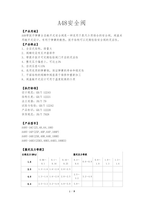
A48安全阀【产品用途】A48带扳手弹簧全启敞开式安全阀是一种适用于蒸汽介质场合的安全阀,阀盖采用敞开式设计,有利于弹簧的散热,扳手结构可以定期检验安全阀的灵活性。
【产品特点】1、全启式结构,排量大2、阀瓣处设有反冲盘部件3、带提升扳手可定期检验阀门开启的灵活性4、整定压力偏差小,可达±3%5、启闭压差≤15%6、选用优质的弹簧钢,保证弹簧的寿命和稳定性7、平面结构的阀瓣和阀座易于维修和重新加工8、阀盖敞开式设计可用于温度较高的介质【执行标准】设计规范:GB/T 12243结构长度:GB/T 12221法兰连接:JB/T 79试验与检验:GB/T 12242产品标识:GB/T 12220供货规范:JB/T 7928【产品型号】A48Y-16C(25,40,64,100)A48Y-16P(25P,40P,64P,100P)A48Y-16R(25R,40R,64R,100R)A48Y-16R3(25R3,40R3,64R3,100R3)【整定压力等级】公称压力(MPa)整定压力等级1.60.06~0.10.1~0.160.16~0.250.4~0.60.6~0.80.8~1.01.0~1.31.3~1.62.5 1.3~1.6 1.6~2.0 2.0~2.54.0 1.3~1.6 1.6~2.0 2.0~2.5 2.5~3.23.2~4.06.4 2.5~3.2 3.2~4.0 4.0~5.0 5.0~100 50 125 195 195 690 150 80 200 280 265 935【结构图片】A47安全阀32 25 32 115 105 31240 32 40 135 115 36650 40 50 160 125 39665 50 65 175 160 57080 65 80 175 160 565100 80 100 190 180 597150 100 150 280 260 738【结构图片】[文档可能无法思考全面,请浏览后下载,另外祝您生活愉快,工作顺利,万事如意!]。
安全阀说明书
Knowledge of safety relief valves introducedSafety relief valve is a safe and protected with a valve, opening and closing parts of its external force is normally closed by the state, when the device or media pressure inside the tubes increases, exceeds the value of open automaticallyEmissions through the media outside the system to prevent the medium pressure piping or equipment exceeds the value, safety relief valves are automatic valves, mainly used for boilers, pressure vessels and piping,Control pressure does not exceed the value of personal safety and equipment operation play an important protective role.Safety relief valve by valve opening height can be divided into inching safety relief valve and the entire Kai safety relief valves, safety relief valve inching height of the opening stroke, ≤ 0.05d0 (throat diameter minimum emissions );Kai-type safety relief valves full opening height is ≤ 0.25d0 (minimum emissions throat diameter).Safety relief valve according to the structure form of points to be divided into vertical hammer, lever, spring-type and (pulse), body structure according to points, can be divided into closed and not closed two,Safety relief valve that is closed to exclude the media is not compromised, all along the exit discharge to designated location, usually used in the toxic and corrosive media, for the safety of air and steam pressure relief valve,To use more safety relief valve is not closed, the safety relief valve products for the selection of the actual sealing pressure should be determined. For the spring-loaded safety relief valve, in a nominal pressure (PN) within theWorking pressure level has several springs, except as noted when ordering safety relief valve type, name, medium and temperature, there should specify the pressure valve seal, or by the maximum sealing pressure supply.Safety relief valve installation and maintenance should note the following, a variety of safety relief valve should be installed vertically, the safety relief valve outlet should be no resistance, to avoid the phenomenon of pressure, safety relief valve should be specifically tested before installation and check its official seal, the use of the safety relief valve should be checked regularly.First, knowledge of safety relief valves overviewSafety relief valve is boilers, pressure vessels and other pressure equipment subject to important safety accessories.Reliability and performance of its action is directly related to equipment and personal security, and with energy conservation and environmental protection are closely related.Second, the definition of safety relief valves safety relief valve called the broad sense, including relief valve, from the rules point of view, directly installed in the steam boiler or pressure vessel onThe necessary conditions must be approved valve technology supervision department, called the safety relief valve on the narrowly defined, other general discharge valve.Safety relief valves and relief valves in the structure and performance is very similar, both are more than open automatically when the discharge pressure of the internal medium, to ensure plant safety. By the existence of such a nature similar to the dry nature, it is in use,Often confuse the two, In addition, some production facilities are also provided in the rules which can be used. Therefore, the difference between the two is often overlooked. So also there were many problems.If you want to make a more precise definition, may be in accordance with the "ASME Boiler and Pressure Vessel Code"First articulated in the definition to understand,1, the safety relief valve (SafetyValve) a static pressure from the valve before the media-driven automatic pressure relief device, characterized by a sudden opening of all open action. For gas or steam applications.2, the relief valve (ReliefValve), also known as a kind of relief valve before the media by the static pressure-driven automatic pressure relief device. It opened with the pressure exceeds the growth of power in proportion to open. Mainly used for fluid situations.3, the safety relief valve (SafetReliefValve), also known as pressure safety relief valve of a media driven by the automatic pressure relief device.Use different according to both valid for the safety relief valve is also valid for the relief valve. Japan, for example, to the safety relief valves and relief valves to less clearly defined,General large-scale energy storage such as a boiler pressure vessel safety device called the safety relief valve, installed in the pipe or other established facilities in the bleed valve. But under MITI's "thermal technology" of the device an important part of the safety and security,Specify the use of safety relief valves, such as the boiler, superheater, reheater, and so on. In the valve of the lower side with the boilers and turbines phase of the occasion,Relief valve to be installed or safety relief valve. This view, the safety relief valve is more reliable than the relief valve requirements. In addition, from the Japanese Ministry of Labor's high-pressure gas management rules,Ministry of Transport and Shipping Association rules at all levels, the identification of safety and emissions regulations, we take the guarantee of emissions called safety relief valves,Not guarantee emissions valve called the relief valve. Kai in the country regardless of type or Weiqi collectively referred to as safety relief valve.Third, the safety relief valve selection1, the safety relief valve of the classification, the current mass production of the safety relief valve spring and the rod are two major categories. There are also impulse-type safety relief valves, safety relief valve, safety valve switch,Safety release valve, the static weight safety relief valve. Spring-loaded safety relief valve spring force and rely mainly on the work of the spring-type safety relief valve in the closed and not closed, generally flammable,Explosive or toxic media should use closed, steam or inert gas used is not closed, the spring-loaded safety relief valve with a wrench in there and without wrenches. Wrench key is to examine the role of the flexibility of the disc, and sometimes can also be used manually with emergency relief. Lever-type safety relief valve lever hammer rely mainly on the force and work,However, the safety relief valve lever is often bulky and limit the range of choice. At high temperature safety relief valve with a radiator. The main parameters of the safety relief valve is the displacement,The displacement depends on the caliber of the valve seat and valve opening height, from the opening height, then divided into Weiqi and all Kai two.Weiqi is the valve opening height for the seat throat diameter of 1 / 40 ~ l/20. All Kai is the valve opening height of seat throat diameter of 1 / 4.2, the selection of the safety relief valve, operating pressure determined by the nominal pressure safety relief valve, operating temperature determined by the use of safety relief valves temperature rangeSecurity from the calculated value of constant pressure relief valve spring or lever decide the scope of constant pressure, then under the decision to use media materials and the safety relief valve structure type,According to the safety relief valve Discharge calculated safety relief valve throat diameter. The following is the safety relief valve used in the general rule.(L) hot water boilers generally is not closed with a wrench inching safety relief valve.(2) steam boiler or steam pipe generally is not closed with a wrench for type safety relief valve.(3), water and other liquids can not be closed for general use compressed medium inching safety relief valve or safety relief valve.(4) high-pressure water supply general use of closed-type safety relief valve, such as high pressure feedwater heater, heat exchanger.(5) gas and other compressible medium for general use of closed-type safety reliefvalve, such as the gas tank, gas pipelines.(6) E-class steam boilers generally static weight safety relief valve.(7) large diameter, large displacement and high pressure systems typically use pulse type safety relief valve, such as temperature and pressure reduction equipment, boiler, and so on.(8) transportation of liquefied gas tanker train car tanker, tanks and other general use built-in safety relief valve.(9) tank top general, hydraulic safety relief valve, to be used in conjunction with the breathing valve.(10) underground water or gas pipes for general use safety relief valve.(11) Liquefied petroleum gas station can pump liquid return pipe back to normal with the safety valve.(12) or negative pressure during operation may have negative pressure systems generally use vacuum safety relief valve.(13) back pressure and toxic volatile flammable container or piping systems are generally used bellows safety relief valve.(14) medium low freezing point of the system is generally used in thermal insulation jacket safety relief valve.Mainly consists of the following categories,(1) (API526 Wire Joints safety relief valve) (Wire Joints safety relief valve) based American Standard system.Chemical equipment with safety relief valve connection sizes are generally in accordance with this standard, as shown.All of the standard nominal diameter of DN15 ~ DN200 (l / 2 "~ 8"), nominal pressure of 0.1 ~ 2500bar, throat diameter from D-T (9.5 ~ 146mm).Comparison of the standard scientific norms, pressure, material, temperature, throat diameter and so overall consideration. Throat diameter determined in accordance with specifications, the same throat diameter can have several specifications,On the contrary may be the same size pipe diameter can choose several. Such as 4 "to 6" diameter pipe with L, M, N, P are four to choose from.(2) the greatest impact in the international company based in Germany KER safety relief valve (KDA21W) series.Commonly known as safety relief valves,As shown, the safety relief valve from the main valve and pilot valves, pilot valve operating the main valve is opened and closed. The valve displacement large; from the impact of back pressure;Can be very close to not leak under pressure to open operation; advantages, such as blowdown. Generally applicable to natural gas pipelines.No current international standards and safety relief valve connection size standards. And this type of valve development, no widely.According to my factory experience and available information, the international standards of most manufacturers in accordance with the API design and manufacturing data, such as Germany. Corey Valve Co., Ltd.Anderson Greenwood (AndersonGreenwood & Co.) And so on.4, the throat diameter of the throat diameter calculated according to the calculation of the general, "Boiler and Pressure Vessel Safety Technical Code" in accordance with APIRP520 refinery pressure relief system design and installation of the first part of the recommended implementation of the method of design "Listed in the formula. The results of these two formulas the same or not materially different.(9) tank top general, hydraulic safety relief valve, to be used in conjunction with the breathing valve.(10) underground water or gas pipelines general safety relief valve with the pilot.(11) Liquefied petroleum gas station can pump liquid return pipe back to normal with the safety valve.(12) or negative pressure during operation may have negative pressure systems generally use vacuum safety relief valve.(13) back pressure and toxic volatile flammable container or piping systems are generally used bellows safety relief valve.(14) medium low freezing point of the system is generally used in thermal insulation jacket safety relief valve.Mainly consists of the following categories,(1) API526 "steel flanged safety relief valve" (FlangedSteelSafetyReliefValve)-based American Standard system.Chemical equipment with safety relief valve connection sizes are generally in accordance with this standard, as shown.All of the standard nominal diameter of DN15 ~ DN200 (l / 2 "~ 8"), nominal pressure of 0.1 ~ 2500bar, throat diameter from D-T (9.5 ~ 146mm).Comparison of the standard scientific norms, pressure, material, temperature, throat diameter and so overall consideration. Throat diameter determined in accordance with specifications, the same throat diameter can have several specifications,On the contrary may be the same size pipe diameter can choose several. Such as 4 "to 6" diameter pipe with L, M, N, P are four to choose from.(2) the greatest impact in the international company based in Germany Corey safety relief valve (PilotOperatedPressureReliefValves) series.Commonly known as pilot-type safety relief valve,As shown, the pilot safety relief valve from the main valve and pilot valves, pilot valve operating the main valve is opened and closed. The valve displacement large; from the impact of back pressure;Can be very close to not leak under pressure to open operation; advantages, such as blowdown. Generally applicable to natural gas pipelines.No pilot present international safety standards and pressure relief valve connection size standards. And this type of valve development, no widely.According to my factory experience and available information, the international standards of most manufacturers in accordance with the API design and manufacturing data, such as Germany. KER Valve Co., Ltd.Anderson Greenwood (AndersonGreenwood & Co.) And so on.4, the throat diameter of the throat diameter calculated according to the calculation of the general, "Boiler and Pressure Vessel Safety Technical Code" in accordance with APIRP520 refinery pressure relief system design and installation of the first part of the recommended implementation of the method of design "Listed in the formula. The results of these two formulas the same or not materially different.。
安全阀手册
阀门产品样本目录1、A21型PN16~40外螺纹连接弹簧封闭微启式安全阀 (1)2、A21型PN64~100外螺纹连接弹簧封闭微启式安全阀 (2)3、A21型PN160~320外螺纹连接弹簧封闭微启式安全阀 (3)4、A27H-10、A27H-16型外螺纹连接弹簧带扳手微启式安全阀 (4)5、A28H型PN16外螺纹连接弹簧带扳手全启式安全阀 (5)6、A37H、A43H型PN16~40双联弹簧带扳手微启式安全阀 (6)7、A38Y型PN16~40双联弹簧带扳手全启式安全阀 (8)8、A40Y型PN16~64带散热片弹簧封闭全启式安全阀 (10)9、A41H、A41Y型PN16~100弹簧封闭微启式安全阀 (12)10、A41Y型PN160~320弹簧封闭微启式安全阀 (15)11、A42F 、A42Y、KA42Y(抗硫)型PN16~100弹簧封闭全启式安全阀 (17)12、42Y型PN160~320弹簧封闭全启式安全阀 (21)13、WA42Y型PN16~40波纹管弹簧全启式安全阀 (22)14、A44Y型PN16~100弹簧封闭带扳手全启式安全阀 (22)15、A44Y型PN160~320弹簧封闭带扳手全启式安全阀 (26)16、A47H型PN16~40弹簧带扳手微启式安全阀 (27)17、A48Y型PN16~100弹簧带扳手全启式安全阀 (29)18、A48SH型PN16~40弹簧带扳手全启式安全阀 (32)19、A48SH型PN64~160高温高压弹簧带扳手全启式安全阀 (34)20、A42Y-P5545V、A62Y-P55 140V型气控碟形弹簧安全阀 (36)21、A68Y型对焊连接弹簧全启式安全阀 (37)22、A49H-40型主安全阀及配套GA49H-40型冲量安全阀 (38)23、A49Y-100、A49Y-100V型主安全阀及其配套冲量安全阀 (40)24、A69Y-P54140V型DN100主安全阀及其配套冲量安全阀 (42)25、A69Y-100、A69Y-100V型DN150主安全阀及其配套冲量安全阀 (43)26、GA41H型PN16~40杠杆式安全阀 (44)27、GA42H型PN16~100单杠杆式安全阀 (45)28、GA44H型PN16~64双杠杆式安全阀 (47)29、A411F-25、A412F-25、NA42F-25型内装式安全阀 (48)30、JA22H-2.5、JA22W-2.5P型外螺纹连接静重式安全阀 (50)31、FA72W型PN10真空负压安全阀 (51)32、AH42F型平衡式安全回流阀 (52)33、A61型弹簧微启式安全阀 (53)34、AY42H PN400型、LA802Y-600型安全溢流阀 (55)35、石化专用安全阀 (57)36、AQ-20型空压机安全阀 (58)37、LFA46F型先导式安全阀系列 (59)使用范围:本产品可用于石油、化工行业。
安全阀详细参数及介绍
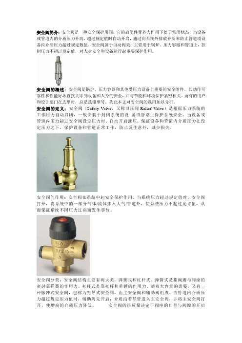
安全阀简介:安全阀是一种安全保护用阀,它的启闭件受外力作用下处于常闭状态,当设备或管道内的介质压力升高,超过规定值时自动开启,通过向系统外排放介质来防止管道或设备内介质压力超过规定数值。
安全阀属于自动阀类,主要用于锅炉、压力容器和管道上,控制压力不超过规定值,对人身安全和设备运行起重要保护作用。
安全阀的概述:安全阀是锅炉、压力容器和其他受压力设备上重要的安全附件。
其动作可靠性和性能好坏直接关系到设备和人身的安全,并与节能和环境保护紧密相关。
而有的用户和设计部门在选型时,总是选错型号。
为此本文对安全阀的选用加以分析。
安全阀的定义:安全阀(Safety Valve,又称泄压阀Relief Valve)是根据压力系统的工作压力自动启闭,一般安装于封闭系统的设备或管路上保护系统安全。
当设备或管道内压力超过安全阀设定压力时,自动开启泄压,保证设备和管道内介质压力在设定压力之下,保护设备和管道正常工作,防止发生意外,减少损失。
安全阀的作用:安全阀在系统中起安全保护作用。
当系统压力超过规定值时,安全阀打开,将系统中的一部分气体/流体排入大气/管道外,使系统压力不超过允许值,从而保证系统不因压力过高而发生事故。
安全阀分类:安全阀结构主要有两大类:弹簧式和杠杆式。
弹簧式是指阀瓣与阀座的密封靠弹簧的作用力。
杠杆式是靠杠杆和重锤的作用力。
随着大容量的需要,又有一种脉冲式安全阀,也称为先导式安全阀,由主安全阀和辅助阀组成。
当管道内介质压力超过规定压力值时,辅助阀先开启,介质沿着导管进入主安全阀,并将主安全阀打开,使增高的介质压力降低。
安全阀的排放量决定于阀座的口径与阀瓣的开启高度,也可分为两种:微启式开启高度是阀座内径的(1/15)~(1/20),全启式是(1/3)~(1/4)。
此外,随着使用要求的不同,有封闭式和不封闭式。
封闭式即排出的介质不外泄,全部沿着规定的出口排出,一般用于有毒和有腐蚀性的介质。
不封闭式一般用于无毒或无腐蚀性的介质。
A42C资料
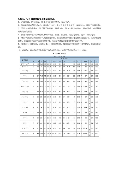
A42C/P/R磅级美标安全阀结构特点:
1、结构紧凑,造型美观,铸件多采用精密铸造,表面光洁。
2、阀座和阀体采用分体式,阀座易于加工,密封面易研磨成镜面,保证密封,且便于装拆维修。
3、设计合理的反冲盘与调节圈子相匹配,调整方便,使安全阀开启迅速,回座及时,可以得到理想的启闭压差。
4、阀座和阀瓣均采用堆焊钴基硬质合金,耐磨,耐冲蚀,密封有保证,延长了使用寿命。
5、背压平衡式安全阀采用军品波纹管制作,能有效地消除背压对起跳压力的影响,还能对有腐蚀性,有毒的介质起严密的隔离作用,防止介质腐蚀阀门内件和污染环境。
6、弹簧作为关键零件,均经过24小时恒温处理,确保其在工作状况中刚度稳定,起跳动作正确。
7、对阀体、阀座等受压件都做严格的耐压试验,确保了使用时的安全、可靠。
A42C/P/R-150型。
- 1、下载文档前请自行甄别文档内容的完整性,平台不提供额外的编辑、内容补充、找答案等附加服务。
- 2、"仅部分预览"的文档,不可在线预览部分如存在完整性等问题,可反馈申请退款(可完整预览的文档不适用该条件!)。
- 3、如文档侵犯您的权益,请联系客服反馈,我们会尽快为您处理(人工客服工作时间:9:00-18:30)。
弹簧全启式安全阀产品使用说明书上海阀门厂有限公司第 1 页共 8 页弹簧全启式安全阀使用说明书1. 主要用途该安全阀主要用于受压设备、容器和管道上作为超压保护装置。
当设备超压并达到预定值(整定压力)时,阀门开启,继后全量排放,以防止设备压力继续升高。
当压力降低到规定值(排放压力)时,阀门关闭。
从而保护设备安全运行。
2.作用原理及其结构、特点2.1作用原理在被保护的承压系统处于正常工作状态时,作用在安全阀阀瓣上的弹簧力同介质作用力及阀瓣和阀座间密封力相平衡,安全阀处于密封状态。
随着系统压力的逐渐升高,阀瓣和阀座间的密封力随之减小,当系统压力升高至规定值时,阀瓣和阀座间的密封力减小到零,阀瓣随即开启,安全阀开始排出介质。
系统压力继续上升,当达到一定值时,阀瓣被提升到规定高度,安全阀处于全开状态,此时安全阀开始大量排出介质,达到安全阀的额定排放量。
随着系统介质的不断排出,系统压力逐渐降低,当系统压力降低到规定值时,安全阀在弹簧的作用下,阀瓣自动关闭,并与阀座保持密封状态,避免系统介质过多排出,影响系统运行的经济性。
2.2 结构特点2.2.1 阀座与阀体用螺纹连接,为可分离式,维修方便、经济。
2.2.2 采用调节圈结构,阀瓣在较小超压下就能够迅速地全开启,排出介质,从而达到保护设备安全运行的目的。
2.2.3 对阀瓣和导向套、阀杆和调整螺杆的材料进行合适的选择以及合理的间隙配合,保证阀瓣运动灵活。
2.2.4 阀瓣材料采用304不锈钢,密封性好,抗腐蚀能力强。
阀座密封面堆焊STELLITE硬质合金,表面精研后保证了安全阀的高密封性,延长了安全阀的使用寿命。
2.2.5 弹簧材料选用50CrV A,可用于工作温度≤300℃的场合,弹簧加工工艺讲究,并进行严格的测试和检查。
3. 主要技术参数3.1 遵循的标准安全阀遵循API 520标准要求进行设计和制造。
密封性能按API527标准的规定;进出口突面连接法兰标准按照ANSI B16.5。
阀门结构长度按API526标准。
3.2 主要性能参数如下:主要性能参数整定压力Mpa 排放压力Mpa回座压力Mpa密封压力Mpa最高工作温度工作介质Ps ≤1.1 Ps ≥90% Ps90%Ps 300℃气体等3.3装配图全启式安全阀SFA-42C3.4 主要零件材料如下:零件名称阀体阀座密封面弹簧阀盖阀杆材料WCB 304 Stellite 50CrV A WCB 2Cr134. 储存、维护保养和安装要求4.1 安全阀从出厂到安装使用之前如果搬运和存放欠妥当,会对阀门性能带来有害的影响,甚至使阀门遭受损伤。
安全阀一般应装箱运输,并在箱内加以固定,尽量使安全阀竖直固定。
运送时应避免剧烈振动。
存放在干燥通风的室内。
无论在运输或存放期间,其进出口都应堵塞。
4.2 如长期存放应作定期检查,消除污垢,并在加工面上涂以防锈油,防止生锈。
4.3 安装前应将阀门清洗干净,并消除在运输过程中造成的缺陷。
4.4 安装时必须仔细核对阀门上的标志和标牌,是否与使用要求相符。
4.5 安全阀应直立安装,并经常保持清洁,安装位置必须注意检修方便。
4.6 安装安全阀的设备和管道中的介质应保持清洁。
4.7 安全阀全部调整完毕后应进行铅封,以防止随意改变已调整好的状态。
4.8 其它操作技术管理应按照国家劳动部颁布的有关安全规程办理。
5. 可能发生的故障及其消除办法。
安全阀使用不当,会造成阀门故障。
这些故障如不及时消除,则会影响阀门的功能和寿命,甚至不能起到安全保护作用。
常见的故障有:5.1 阀门泄漏:即在设备正常工作压力下,阀瓣与阀座密封面间发生超过允许程度的渗漏。
其原因可能是:(1) 脏物落到密封面上。
把脏物冲去,清洁密封面;(2) 密封面损伤。
应根据损伤程度,采用研磨或车削后研磨的方法加以修复。
修复后应保证密封面平整度,其粗糙度应不低于Rz0.8;(3) 由于装配不当或管道载荷等原因,使零件的同心度遭到破坏。
应重新装配或设法消除管道附加的载荷;(4) 阀门开启压力与设备正常工作压力太接近,造成密封比压力过低。
当阀门受振动或介质压力波动时容易发生泄漏。
应根据承压设备超压保护要求,调整开启压力;(5) 弹簧松驰从而使整定压力降低从而引起阀门泄漏。
可能是由于高温或腐蚀等原因所造成,应根据引起泄漏的原因采取调整弹簧提高整定压力或更换弹簧甚至调换阀门(如果属于选用不当的话)等措施。
如果仅仅是由于调整不当所引起,则只需把调整螺杆适当拧紧。
5.2 阀门启闭不灵活。
其主要原因可能是:(1)调节圈调整位置不当,致使阀门开启过程拖长或回座迟缓,应重新加以调整;(2)内部运动零件有卡阻现象,这可能是由于装配不当,脏物混入或零件腐蚀等原因所造成,应查明原因消除之;(3)排放管道压力过大,排放时建立起较大背压,使阀门开不足。
应减小排放管道阻力。
5.3 阀门振荡,即阀瓣频繁启闭。
其可能的原因如下:(1)阀门排放能力过大(相对于必需排量而言)。
在选用阀门时,应选用阀门的额定排量尽可能接近设备的必需排放量;(2)进口管道口径太小或阻力太大。
应使进口管内径不小于阀门进口通径或者减小进口管道阻力;(3)排放管道阻力过大,造成排放时过大的背压。
应降低排放管道阻力;(4)弹簧刚度太大。
应改用刚度较小的弹簧;(5)调节圈调整不当,使回座压力过高。
应重新调整调节圈位置。
O & M ManualForSpring Loaded Safety ValveShanghai Valve Factory Co., LTDO & M manual for Spring Loaded Safety valveageThe safety valve is used as an overpressure protection for a pressurized equipment, vessel or pipe.As the pressure in the equipment is higher than a set pressure, the valve opens and then fully discharges. As the pressure is lower than the blow down pressure, it closes to protect the equipment and to operate safely.2.Working Principle and Structure Features2.1 Working PrincipleUnder normal working condition in a pressurized system when a spring force exerted on a valve disc, and the medium pressure and a seating force between valve disc and valve seat are kept in balance, the safety valve will keep in close position. If the system gradually increases the pressure, the seating force between the valve disc and valve seat decreases accordingly. When pressure in the system goes up to a set pressure, the seating force reaches to zero. At this moment the valve disc immediately opens discharging the medium. If the pressure in system keeps going on up to a certain value, the safety valve fully opens. Under such condition large quantity of medium will go out and reach the rated discharging capacity. As the medium discharges out, the pressure gradually reduces, While the pressure reaches to the blow down pressure, the valve disc automatically shuts down by means of spring force and keeps seating with valve seat, preventing the equipment from undue discharging medium and influencing normal operation.Structure FeaturesThe valve body and disc are renewable by means of threads. This is convenient in maintenance and economic.A adjusting ring is used So that the disc can quickly open and discharge at a small over-pressure and keep the equipment safe.The materials of the valve disc and guide sleeve, stem and adjusting bolt are properly chosen with reasonable clearances to ensure movement of the valve disc smoothly.The valve disc is made of 304austenitic stainless steel with high excellent corrosion resistance. The seating surface of valve seat is overplayed with STELLITE and lapped to ensure excellent seal reliability and to prolong service life of valve.The spring is made of material 50CrV A and carefully fabricated, strictly inspected and tested. It can be used at temperature≦300℃.3. Main Technical Parameters3.1 Applicable StandardsThe valve is Designed and manufactured in accordance with API 520. Its leakage rate confirms to API 527. Its RF flange ends and Face-to-face dimensions are as per ANSI B16.5 and API 526 respectively.3.2 Its specification as follows:Set P. Mpa Discharge P.MpaBlow down P.MpaClosure Test P.MpaWorkingTemp. ≦WorkingmediumPs ≤1.1 Ps ≥90% Ps 90%Ps 300℃Air etc.3.3 Assemble DrawingThe Safety valve SFA-42C is shown on Fig 1.Fig 1 Safety valve SFA-42C3.4Materials of Main PartsPart name Body Seat Seating sur. Spring Bonnet Stem Material WCB 304 Stellite 50CrV A WCB2Cr134. Storing, Maintenance and Installation4.1 In order to prevent from damage during transportation, handling and storage the safety valve shallbe packed in a wooden crate and firmly fixed in vertical direction. Intensive vibration must be avoided during transportation. It shall be stored in a dry and well-ventilated room. Its inlet and outlet both shall be plugged with plastic covers during transportation or storage.4.2 All machined surfaces shall be cleaned and then laid with anti-rusting oil or grease, moreoverperiodic inspection shall be carried out provided the valve will be stored for long time.4.3 Before installation the safety valve shall be cleaned up and any defect shall be eliminated resultedduring transportation.4.4 Carefully checking if its nameplate and marks are correct.4.5 The safety valve shall be vertically installed, the stem is upward and convenience in maintenanceshall be taken into consideration.4.6 The equipment fitted with safety valve and the medium in pipe shall keep clean.4.7 A lead seal shall be made after adjustment of the safety valve to avoid to randomly changing ofadjusted condition.4.8 The safety valve should be in accordance with the safety regulations issued by the National LaborMinistry.5. Possible trouble and remedy Possible trouble and remedyAny trouble with the safety valve caused by incorrect use and mal-operation shall be eliminated at any time. Otherwise it will have an adverse effect on its function and service life, even refuse to act as an overpressure protection.The troubles usually meeting are as follows:5.1 Valve leakage.Leakage over permissible quantity from seating surfaces between valve disc (4) and nozzle (2) appears at a normal working pressure. The causes probably include the following:(1) The seating surfaces are dirt. Solution: cleaning up the seating surfaces.(2) The seating surface are damaged. Solution: repairing the damaged surfaces by means oflapping the surfaces, or first machining, grinding and then lapping them as the case may be.The repaired surfaces must be flat with roughness not less than Rz0.8.(3) Misalignment of parts caused by incorrect assembly or piping load, etc. Solution: re-assembleit or getting rid of additional piping load.(4) Its set pressure is too close to normal working pressure so that a seal off force ratio is too small.In this case the valve is easy to leak while the valve is vibrating or a medium pressure is fluctuating. Solution: Readjusting its set pressure according to the requirement of the equipment’s overpressure protection.(5) The set pressure decreases because of a loose spring (6). This probably results from hightemperature or corrosion. Solution: following respective measures may be taken according to different causes: increasing the set pressure by adjusting spring, or displace the spring, or even displace the valve if the valve is incorrectly selected. In case of incorrect adjustment of spring, adjusting properly the adjusting bolt.5.2 Not nimble open –close actions of valve. The causes may be as follows:(1) The adjusting rings is not in right position so that opening valve is elongated and reseating isdelayed. Solution: readjustment.(2) Internal moving parts are stuck. This maybe results from improper assembly, or foreignmatters, or corroded parts. Solution: find out cause and then put it right.(3) The pressure in discharging pipe is too high resulting in undue back- pressure. Solution:reducing the resistance in discharging pipe.(2) Internal moving parts stick. Solution: make inspection and elimination.5.3 The disc frequently opens and closes so that the valve is shattering. The possible causes are as follows:(1) The discharge capacity of the valve is much higher than necessary one. In selection of valve itsrated discharging capacity should be close to necessary discharge of the equipment as far as possible.(2) The diameter of an inlet pipe is too small or its flow resistance too high. Solution: making the inner diameter of the inlet pipe not less than inlet diameter of valve, or reduce its resistance in the pipe.(3) A big flow resistance in discharging pipe makes back pressure in discharging big. Solution:reducing flow resistance in discharging pipe.(4) The spring (6) is too stiff. Solution: displace it with a spring of less stiffness.(5) The adjusting ring is improperly adjusted so that the reseat pressure is too high. Solution: readjusting the adjusting ring.。