mastercam五轴加工教程
数控五轴加工中心编程的方法及步骤
数控五轴加工中心编程的方法及步骤小伙伴!今天咱们来唠唠数控五轴加工中心编程这个事儿。
一、了解加工零件。
咱得先好好看看要加工的零件长啥样。
就像认识新朋友,得知道它的轮廓、尺寸、精度要求这些。
你得清楚哪里是平面,哪里是曲面,有没有啥特殊的形状。
这就好比给零件做个全身检查,心里有数了,编程的时候才能有的放矢。
二、确定加工工艺。
这一步可重要啦。
要想清楚用啥刀具合适呢?大零件和小零件用的刀具可能就不一样。
还有切削的参数,就像炒菜放多少盐、多少油一样,切削速度、进给量、切削深度都得定好。
这得根据零件的材料来,要是硬邦邦的材料,那切削参数就得小心调整,不然刀具可能就受不了啦。
工艺路线也得规划好,先加工哪里,后加工哪里,就像规划旅行路线一样,得合理安排。
三、建立坐标系。
这个就像是给零件在加工中心里找个家。
确定一个原点,然后X、Y、Z轴就像房间的坐标一样,每个点都有自己的位置。
五轴加工中心还有两个旋转轴呢,这两个轴的坐标系也要确定好。
这就像给零件的每个部分都贴上了地址标签,加工的时候刀具才能准确找到地方。
四、编写程序。
现在就开始正儿八经写程序啦。
用那些编程代码,像G代码、M代码之类的。
比如说G00就是快速定位,让刀具快速跑到指定位置。
编写的时候要按照之前确定的加工工艺来。
如果有曲面的话,可能得用一些特殊的编程方法,像宏程序之类的。
这就像写作文,要按照一定的逻辑和规则来写,不能乱写一气。
五、模拟加工。
程序写好可别着急让加工中心干活。
先模拟一下,就像演习一样。
看看刀具的路径对不对,有没有可能撞到零件或者夹具。
要是模拟的时候发现问题,那就赶紧修改程序。
这就像出门前检查一下东西有没有带齐,发现没带钥匙还能及时补上。
六、实际加工。
经过前面的步骤,没问题啦,就可以让加工中心开始干活啦。
不过在加工的时候也不能完全不管,得盯着点。
万一有啥突发情况,像刀具磨损啦,还能及时处理。
数控五轴加工中心编程就是这么个事儿,看起来有点复杂,但是只要一步一步来,多实践,肯定能掌握的。
五轴加工工作流程及基本原理

五轴加工工作流程及基本原理摘要:简洁扼要说明五轴加工流程,并对关键节点工作原理展开详细说明。
应用齐次变换法,对五轴CAM刀位数据及后处理机床各轴运动进行数据建模求解,该方法简便易于理解。
关键词:五轴加工;CAM;程序后处理;齐次变换引言目前越来越多领域对其产品的设计要求日益提高,除了传统航天航空、汽车轮船等领域经常用到大曲率的曲线表面,以达到较高的空流体力学性能,日常用品因功能外观要求,也开始使用越来越多的自由形状。
传统3轴加工仅可加工一个单凸曲线特征的表面,对复杂曲线变化的表面(深凹或低切)无能为力,此时需要使用5轴加工。
另外对形状尺寸公差要求严格的产品,也可采用5轴一次装夹进行多面加工,避免多次装夹导致精度损失。
成功的5轴加工取决于4个不同程度互相依赖的因素:●机床(床身结构刚性、主轴稳定性、传动系统精度等)●控制硬件(电机、反馈部件、驱动器等)●控制软件(数控系统运动、插补算法等)●工艺编程软件(刀具轨迹的生成和后处理)综述所述,在5轴加工中,机床、控制系统、刀具夹具等纯技术性能并非影响最终结果的唯一因素,结果的质量在很大程度上取决于支持整个工艺的设计工具(特别是CAM软件)的正确使用。
本文就第4点展开详细说明,对5轴加工工作流程及基本原理进行简介。
1.五轴加工工作流程简介如图1所示,五轴加工工作流程大致如下[1]:1)产品3D设计根据产品的功能及外观要求,利用CAD设计软件进行3D设计,CAD设计软件提供多种自由曲面造型,主要有Coons曲面、Bezier曲面、B样条曲面等,另外3D设计软件一般可与有限元分析软件、CAM软件进行结合对接,为产品设计优化、后续加工制造提供好的支持。
常用的CAD设计软件有:UG、Pro/E、SolidWorks等。
2)刀具位置文件生成输入产品的3D造型文件,利用CAM软件对刀具类型及参数、工艺方案、刀轴控制方式、刀具路径规则等进行设置,并计算生成刀具位置文件(该计算处理称为CAM的主处理)。
worknc五轴编程手册

WorkNC G3 V19 Training Guide: 5-Axis03/05/07Table of Contents Table of Contents1Prerequisites 1-1 2General Principles for 5-Axis Machining 2-1 35-Axis Machining Parameters 3-1 3.1Machining Zone and Surface Selection for 5-Axis 3-1 3.2Selection of the 5-axis machining method 3-1 3.3Selection of the tool orientation 3-2 3.4Lead-in selection 3-4 3.55-Axis Parameters 3-5 3.6Curve Machining Options 3-7 3.7Selection of the guide curve 3-7 3.8Selection of the change of direction in corners 3-8 3.9Tool Offset Distance 3-10 3.10Tool Offset Angle 3-10 45-Axis Rolling 4-1 4.15-Axis Rolling - Machining Strategy 4-4 4.2Lab: 5-Axis Rolling 4-6 55-Axis Pocketing 5-1 65-Axis Planar Finishing 6-1 6.1Lab: Planar Finishing 6-1 7Z-Level Finishing - Blade Machining 7-1 7.1Lab: Z-Level Finishing - Blade Machining 7-1 85-Axis Parallel to Curve 8-1 8.1Lab: 5-Axis Parallel to Curve 8-1 95-Axis Perpendicular to Surface 9-1 9.1Programming 5 Axis Perpendicular to Surface 9-1 105-Axis Normal to Surface 10-1 10.1Lab: Normal to Surface 10-2 11Grooves 11-1 125-Axis Profiling 12-1 12.15-Axis Profile: Surface Contact Detection 12-1 12.2Lab: Profiling 12-3 134-Axis Profiling 13-1 13.1Programming a 4-Axis Profile toolpath 13-1 14Rolling between Curves 14-1 15Blade Machining 15-1 15.14-Axis Spiral Blade Roughing and Finishing 15-1 15.24-Axis Spiral Blade Remachining 15-4 16Impellers 16-1Table of Contents16.1Programming 5-Axis Impellers Roughing 16-116.2Programming a 5-Axis Impellers Finishing 16-516.3Programming 5-Axis Impeller Remachining 16-6175-Axis Hole Boring 17-117.1Lab: 5-Axis Drilling 17-318Editing Toolpaths 18-118.1General Points 18-118.2Modification of a point 18-218.3Modification of normals 18-518.3.1Normal Selection Types 18-518.3.2Editing Functions for Normals 18-918.4Wizard 18-1019Collision Check 19-119.1General Points 19-119.2Display of the machine 19-219.3Activating Detection and Collision Properties 19-219.4Collision Settings 19-319.5"Toolpath Properties" Panel 19-419.6Representation of Collisions in VisuNC 19-6Prerequisites11 PrerequisitesThis training session and its related manual require that the user has a good working knowledge of WorkNC. He must know how to activate parts, create and edit toolpaths.2 General Principles for 5-Axis MachiningThe G3 V19 version of WorkNC is delivered with twenty 5-axis toolpaths. All of them are milling toolpaths, except a drilling toolpath and a laser cutting toolpath.The surface part construction is very important when using 5-Axis toolpaths. In most cases, the tool orientation is directly linked to the U and V parameters of the surfaces.Most toolpaths require the use of context surfaces to select the surfaces to machine, others require the use of one or more guides curves, etc.For 5-axis machining, a surface is made of a profile and a face. The position of the tool on the surface depends on the selected toolpath, especially for "rolling" and "profiling".E.g.:Surface to machine:Rolling:Profiling:Machining normal to Surface:5-Axis Machining ParametersMachining Zone and Surface Selection for 5-Axis33 5-Axis Machining ParametersAll standard parameters may be used, except boundary curves and machining planes which are never used for 5-axis machining.1. Selection of a machining zone2. Selection of context surfaces3. Selection of the machining method4. Selection of the tool orientation5. Lead-in selection6. Selection of the curve to machine7. Selection of the change of direction in corners 8. Position of the tool on the surface 9. 5-Axis Parameters10. Surface in relation to which the tool is oriented3.1 Machining Zone and Surface Selection for5-AxisIt is not possible to use "Boundary Curves" or "Machining Planes": only Window and View parameters are available. In some cases, the use of a view allows defining which side of the surfaces are machined. This is for example the case for the Perpendicular to surface toolpath.3.2 Selection of the 5-axis machining methodYou can usually choose any of the threeavailable machining methods. This means that the direction of the guide curve as it wascreated has no importance.NOTEStart point of the guide curveWhen using a closed curve, the point used as starting point to create the guide curve is important since the toolpath will start from that exact point.35-Axis Machining Parameters Selection of the tool orientation3.3 Selection of the tool orientation(5-Axis) Machining Direction Dialog BoxSurface definitionFor 5-Axis programming, it is very important that surfaces are correctly defined: the tool orientation depends on the U and V parameters of the surface. Surfaces must have been properly prepared before programming a 5-axis toolpath. E.g.:Surfaces not correctly defined...... wrong toolpath:Surfaces correctly defined... toolpath is OK:The example illustrated with the four images above is a clear representation of the problems that you may encounter. If the U and V surface parameters are not correct and if you choose to follow surface ISO lines, the toolpath may be incomplete or the position of the tool may be wrong. The only solution: change the surface(s) using CAD functions.Other example with wrong positioning of the tool:5-Axis Machining ParametersSelection of the tool orientation3Surfaces not correctly defined...... wrong toolpath:Surfaces correctly defined...... toolpath is OK:The above example shows another type of problem that you may encounter: if the U and V parameters of the surface are not correct and if you chose to follow surface ISO lines, the toolpath may be fully completed but the position of the tool may be wrong. Again, change the surface(s) using CAD functions.In case of problems when following surface ISO lines, you can also try the other option called "Perpendicular to curve": it may give better results.(5-Axis) Machining Direction Dialog Box - Perpendicular to CurveFollow surface ISO lines: Perpendicular to curve:35-Axis Machining Parameters Lead-in selection3.4 Lead-in selectionIf you have enough room to position your tool outside the machining zone without any risk of collision with the part or any clamping equipment, you can choose among different machining lead-ins, depending on your own preferences.Radial lead-in with tangency extensionVertical Lead-inRadial Lead-inLead-in with tangency extension3.55-Axis Machining Parameters35-Axis Parameters 3.6 5-Axis ParametersMaximum head rotationThis parameter is used to specify the rotation amplitude ofthe machine head not to be exceeded. This maximumamplitude directly depends on the technical constraints of themachine. When the inclination angle of a surface to machineis higher than this value, the toolpath does not give anyresult. This parameter does not apply to all 5-axis toolpaths.This parameter allows you to indicate the machine capabilityto reach such angle values or not.1. Vertical head 0°2. Maximum amplitude from – 40 to + 40°The opposite picture illustrates this amplitudeparameter. In this case, a surface to 45° could not bemachined.Vector tolerance for smoothingThis parameter allows defining a maximum angle within which the tool can be adjusted onits axis to obtain a smoother toolpath and avoid vibrations of the machine head. If you setthe value to 3°, each of the vectors can "deviate" by a maximum of 3°. This parameter isalways combined with the smoothing distance.35-Axis Machining Parameters 5-Axis ParametersSmoothing DistanceThis is the length over which WorkNC tries to smooth the toolpath. This value applies both forwards and backwards with respect to each point of the toolpath and in the machining direction.Smoothing vector (5°) Smoothing Distance: 1 mmSmoothing vector (45°) Smoothing Distance: 30 mmsVector toleranceThis parameter offers the possibility of reducing/increasing the number of points in atoolpath. If consecutive point vectors along a longitudinally straight section of the toolpath have vector angle variations within the limit of this user defined tolerance, then these points will be eliminated. This tolerance cannot exceed 5°.Setting this parameter with a small value can be useful when working on recent millingcenters with the latest CN controllers which function better with toolpaths containing a large number of points. Alternatively, a higher value will produce a smaller number of points which is more appropriate to older generation milling centers.Vector tolerancePicture 1: Tolerance = 1° Picture 2: Tolerance = 4° Picture 3: Tolerance = 0.1°5-Axis Machining ParametersCurve Machining Options33.7 Curve Machining OptionsBasically, these options operate in the same way as 2D toolpaths for which he same type of parameters is available.Z-steps are completed to gradually approach the curve to machine.These parameters allow you to machine directly onto the surface or to proceed by level, especially during the roughing phase which requires large quantities of material to be removed.Examples :Approach of the curve from + Z:Approach of the curve in the view plane:Machining order, by level:Machining order, by curve:NOTEMachining OrderMachining by curve is similar to machining by zone in 3D toolpaths. The toolpathmachines an area completely then goes machining the next area. When the "by level" option is selected, the number of retracts in the toolpath is higher.3.8 Selection of the guide curve3 5-Axis Machining ParametersSelection of the change of direction in cornersToolpath Parameters - Curve to machineYou must specify the curve to machine. Note that "Curve to machine" means the drive curve.3.9 Selection of the change of direction incornersThe "non-tangency condition" allows managing changes of direction in sharp corners. Twooptions are possible: radial or by segment.Radial:5-Axis Machining ParametersSelection of the change of direction in corners3 By segment:NOTE By segmentWith the "Segment" option, the edge to machine is protected as the tool does not "roll" on it.35-Axis Machining Parameters Tool Offset Distance3.10 Tool Offset DistanceThe Tool Offset Distance parameter defines the axial distance between the center of the tool tip or tool end and the perpendicular point of the curve on the tool axis. By default, if the value is set to 0, the center of the tool tip or tool end is positioned on the curve during toolpath calculations.Picture 1:Picture 2:1. Surface to machine2. Curve to follow and upper surface (2/2a)3. Lower surface4. Controlled point of the tool (center of the tool)5. Offset distanceThe picture # 1 shows the theoretical position of the tool against the machined curve. The picture # 2 shows the position of the tool with an offset value which corresponds to the tool radius.Toolpath example:With a negative offset3.11 Tool Offset AngleThe forward offset angle allows you to define a lead or lag angle with respect to the normal to surface position along the toolpath trajectory.Defining a positive value will result in a lead angle (forward inclination) and a negative value will give a lag angle (backward inclination).This promotes better cutting conditions and improves surface finish quality.5-Axis Machining Parameters3Tool Offset AngleForward Offset Angle = 10°1 Surface2 Tool trajectory direction3 Toolpath pointA positive value of 10° has been entered for the above example so the tool will be inclined in a forward direction with respect to the tool trajectory direction.This specific parameter is not available in all 5-Axis toolpaths but can be used for 5-Axis Planar Finishing, Normal to Surface, etc.5-Axis Rolling Tool Offset Angle445-Axis RollingThe Rolling strategy is used - among others - for part trimming.5-Axis Rolling machines with the side of the cutter, tangent to the surface and following the user-defined curve as illustrated in the following diagram.5-Axis Rolling Machining Principle1 Surface2 CurveYou can use this toolpath both for the roughing or finishing phase.NOTESurface constructionThe surface construction is very important when using the Rolling strategy: surfaces must be perfectly ruled.E.g.:45-Axis Rolling Tool Offset AngleRolling: lead-in with "tangency extension"1. Machined surface2. Tangency ExtensionSee Also...• Selection of the change of direction in corners [g 3-8]•5-Axis Rolling4Tool Offset Angle Tool Offset Distance [g 3-10]•Tool Offset Angle [g 3-10]4 5-Axis Rolling5-Axis Rolling - Machining Strategy4.1 5-Axis Rolling - Machining StrategyWe will use the following part to illustrate 5-Axis Rolling machining strategies.Example of 5 Axis Rolling ToolpathThe Surface Group, Guide Surfaces and Curves are defined as follows.Surface Selection Group, Guide Surfaces and CurveThe green surface is defined for machining in the Surface Group. The blue surfaces aredefined as the Guide Surfaces and the Curve to Machine is the yellow curve at the base ofthe island.The resulting toolpath is as shown below.Generated 5-Axis Rolling ToolpathLet’s now take a look at a zoomed view of the cutter tip at a point on the toolpath todetermine its position with respect to the flat surface defined for machining in the SurfaceGroup.5-Axis Rolling45-Axis Rolling - Machining StrategyZoom on Cutter TipYou can see in the above screenshot that the extremity of the cutter makes contact with the flat surface defined for machining (the stock allowance = 0 in this toolpath).If we generate the same toolpath but we define the flat surface as ‘ignored’ in the Surface Group, we obtain the following result.Zoom on Cutter Tip - Ignored SurfaceAs the tool is tangent to the inclined Guide Surfaces and the surface below the cutter tip is programmed as ‘Ignored’, the cutter effectively machines this surface.4 5-Axis RollingLab: 5-Axis Rolling4.2 Lab: 5-Axis RollingOpen the 5axes_1 workzone and create "Rolling" toolpaths by machining the undercutgroove.Use the 5-Axis toolpath parameters to create both 5-Axis roughing and finishing cutterpaths.5-Axis Pocketing555-Axis PocketingThis toolpath has been designed for machining tubular forms (e.g. inlet manifolds). You can machine inclined walls and undercuts without having to define different views to access these areas. The toolpath starts at the top of the pocket and mills deeper.Tool Axis ControlAngle and attraction point...When using both an angle and an attraction point, WorkNC draws a dummy cone whose end is the center of the tool tip when in contact with the surface and inclined to the specified angle value .In this case, the tool is oriented to the specified angle, in the direction of the attraction point.This orientation applies for all points on the toolpath, provided however that the attraction point is correctly positioned.Attraction Point...55-Axis PocketingWhen using an attraction point only, the tool is actually oriented with respect to a line going from the center of the tool tip to the attraction point when the tool is in contact with the surface.This orientation applies for all points on the toolpath, provided however that the attraction point is correctly positioned. When the attraction pointis not properly positioned for a given point on the toolpath, a new position is calculated by WorkNC to avoid collision.Z-Step...You can only use a Z-level machining method. The Z-step value can be fixed or variable. The view that you define is very important since each of the Z-steps in the toolpath is made accordingly. Z-steps are calculated in the plane of the view as shown in the picture below.Cutting direction...You can select a curve to indicate the cutting direction.5-Axis Planar Finishing6Lab: Planar Finishing6 5-Axis Planar FinishingThe Planar finishing toolpath is identical to the 3-Axis strategy. You can use it to machinelarge parts using ball-end or flat tools. The 5-Axis strategy offers the advantage that the toolis always normal to the surface machined or some angle inclined from normal.With the 5-Axis strategy, you can also use an inclined tool to avoid having to mill with theend of the tool tip. Use a tool offset angle [g 3-10] to make sure that the tool inclination iskept constant with respect to surface normals.Tool offset angle1 Inclination Angle2 Normal3 Tool4 SurfaceExample of a 5-Axis Planar Finishing toolpath:6.1 Lab: Planar FinishingThe goal of this lab is to show you how to implement planar finishing using related Objectives...parameters.65-Axis Planar Finishing Lab: Planar Finishing(PC) <Installation directory>: \workncxx\surface\assembly 1. Open the workzone called "Assembly". 2. Create lists of surfaces to machine and implement this strategy with differentparameters.Tool normal to Surface:Tool offset:Part required...Instructions...Z-Level Finishing - Blade Machining Lab: Z-Level Finishing - Blade Machining77Z-Level Finishing - Blade MachiningThe 5-Axis "Z-Level Finishing" toolpath allows you to machine by level parts like turbine blades - as in 3-Axis - with the advantage that all undercut areas of the part are machined too.7.1 Lab: Z-Level Finishing - Blade MachiningThe goal of this lab is to illustrate 5-Axis Z-Level Finishing using related parameters.(PC) <Installation directory>: \workncxx\surface\blades 1. Open the workzone called "Blade machining". 2. Apply this strategy and try various parameters.Objectives... Part required... Instructions...5-Axis Parallel to Curve Lab: 5-Axis Parallel to Curve885-Axis Parallel to CurveThis toolpath is similar to "3D Drive Curve Finishing" in 3-Axis. With the 5-Axis strategy, the tool is always normal to the surface being machined. Most specific parameters are the same as in the 3-Axis strategy. However, you can impose a maximum head rotation angle.NOTEContext SurfacesYou do not need to use context surfaces with this toolpath. If a surface is in undercut along the trajectory, it will not be machined.8.1 Lab: 5-Axis Parallel to CurveThe goal of this lab is to illustrate 5-Axis Parallel to Curve Machining using related parameters.(PC) <Installation directory>: \workncxx\surface\turbine_training 1. Open the workzone called "turbine_training". 2.Create a toolpath to machine the lateral side of the part, as shown in both picturesbelow. Start by creating the toolpath using a machining window and check the results.1: Guide curve2: Undercut area machinedObjectives...Part required... Instructions...5-Axis Perpendicular to Surface9Programming 5 Axis Perpendicular to Surface9 5-Axis Perpendicular to SurfaceThe "5-Axis Perpendicular to surface" strategy is used to quickly rough-machine parts made of many curved surfaces such as bumpers. Machining is made between two curves.WorkNC creates a ruled surface between both curves and creates a toolpath with respect to the normals of this surface projected on to the part.9.1 Programming 5 Axis Perpendicular toSurfaceProgramming a 5-Axis Perpendicular to Surface toolpath mainly consists in defining each of the following elements:1. two curves which will be used by WorkNC to create a ruled surface,2. the surfaces to machine,3. the stepover value,4. the maximum depth value and5. the view, which will be used to define which side you want to be machined.We are going to use the following bumper as an example:Bumper ExampleDefining two curves...It is important that you correctly define the curves that will serve as guide curves since theyare used to define the ruled surface. Normals will be oriented in accordance with this surface.If we consider our example, you could define curves on each side of the bumper. Seecurves 1 and 2 in the picture below:9 5-Axis Perpendicular to SurfaceProgramming 5 Axis Perpendicular to SurfaceDrive Curves for Perpendicular to SurfaceSurfaces to machineNow that you have defined the drive curves, you must indicate the surfaces that you want tobe machined. This is done with a surface list and surface group that you then select in theMachining zone parameters. In our example, you can select all part surfaces.Perpendicular to Surface - Surface SelectionStepover valueDefine a stepover value.5-Axis Perpendicular to Surface9Programming 5 Axis Perpendicular to SurfacePerpendicular to Surface - Stepover ValueMaximum depth valueThe maximum depth value is similar to a machining plane. It is used to avoid machining the inner part of the other side:Example: If you define a maximum depth value which is too big, you will obtain the following:Perpendicular to Surface - Maximum DepthAs you can see the tool machines the opposite side of the part.Machining ViewDefine a view which is above the part and covers all surfaces to machine:9 5-Axis Perpendicular to SurfaceProgramming 5 Axis Perpendicular to SurfacePerpendicular to Surface - Machining ViewThe final result should look like the following:Perpendicular to Surface - Final Result5-Axis Normal to SurfaceProgramming 5 Axis Perpendicular to Surface10105-Axis Normal to SurfaceThis toolpath is generally used for engraving and is similar to the 3-Axis toolpath On-Curve Engraving. It has the advantage that the tool position is always normal to the surfaces being machined or some angle inclined from normal to surface. No matter the surface inclination, the depth of the groove is kept constant.Curves to machine are prepared in the CAD environment of WorkNC.When defining curves in the CAD environment of WorkNC, do not forget to merge them.The inclination of the tool against the normals of the surface is defined by the forward offset angle:105-Axis Normal to Surface Lab: Normal to Surface5-Axis Normal to Surface: Forward Offset AngleSee Also...• Selection of the change of direction in corners [g 3-8] • Tool Offset Angle [g 3-10]10.1 Lab: Normal to SurfaceThe goal of this lab is to illustrate 5-Axis Normal to Surface Machining using related parameters.(PC) <Installation directory>: \workncxx\surface\5_axis_training 1. Open the workzone called "5_axis_training". 2. Create a toolpath using the "engraving" curve.Objectives...Part required... Instructions...Grooves 11 11 GroovesThis toolpath is designed to machine complex grooves that are not accessible in 3-Axis. The cutter is always normal to the surface at the bottom of the groove and requires one or twocurves to define the groove. This strategy can be used to rough and finish grooves. It isparticularly adapted to machine door or window rubber profiles.You can machine grooves with a constant or variable width. Use the specific parameters todefine the groove to machine.11 GroovesGroove DefinitionGrooves11Open groove example1: Guide curveOne single curve is enough to machine this groove. It must be defined at the bottom of the wall. You must also indicate the width of the groove.NOTEWidth of the grooveIn this case, you can indicate a groove width that is higher than the theoretical width forthe tool to go beyond the part.Closed groove example5-Axis Profiling5-Axis Profile: Surface Contact Detection12125-Axis ProfilingThe Profile strategy is especially useful for part trimming. This toolpath may be redundant with rolling. Use it for trimming when you do not have any side surface on which you can use rolling.Here, Rolling is possible...Here, only Profiling is possible...Surface to machineProfile to machineIt machines with the tool normal to the selected surface and tangent to the curve which itfollows.5-Axis Profile Toolpath1 Curve to Machine2 Selected Surface3 Tool Offset DistanceSee Also...• Selection of the change of direction in corners [g 3-8]12.1 5-Axis Profile: Surface Contact DetectionWith this option, you can machine tangent to a curve and normal to bottom surface while detecting contact with neighboring surfaces.Automatic surface limitation detectionIntroduction Benefits125-Axis Profiling5-Axis Profile: Surface Contact DetectionThis parameter allows you to define a curve to machine which is ‘hidden’ by an overlayed surface in the Z axis of the View or the Machining Zone. If the perpendicular distance in the Z axis between the edge of the overlayed surface and the curve is less than or equal to the defined value then machining will be performed along the edge of the overlayed surface. The following examples illustrate how this parameter works.Surface Group, Surface Guide and Curve to Machine Definitions1 Curve to machine2+3 Surface selected for machining and as the Guide Surface 4 Inclined surface which ‘hides’ the curveNOTECurve to MachineIn order to orientate the cutter correctly, the Curve to Machine must always be on the Guide Surface.In the following example the Detection Width is set to 0.Toolpath with Detection Width Value = 0The toolpath is generated along the curve where the walls are vertical as the cutter can ‘see’ the curve. However, no trajectory is generated parallel the curve where inclined, overlaying surfaces are located.The next example shows the toolpath with the Detection Width set to an intermediate value.Toolpath with Insufficient Detection Width Value5-Axis Profiling Lab: Profiling12In this case the toolpath trajectory partially machines parallel to the curve ‘hidden’ by the inclined surfaces. The whole section of the curve ‘hidden’ by the inclined surfaces is not machined because the Detection Width value is too small.In the following example the Detection Width value is sufficient to machine parallel to the whole section of the curve which is masked by the inclined surfaces.Toolpath with Sufficient Detection Width Value to Machine the Complete CurveZ Axis View of the ToolpathThe above screenshot shows how the cutter machines parallel to the curve and against the edge of the overlying surface.12.2 Lab: ProfilingThe goal of this lab is to illustrate Profiling using related parameters.(PC) <Installation directory>: \workncxx\surface\part_ladder 1. Open the workzone called "part_ladder". 2. Create toolpaths by following the profile below.1. Surface to select for profiling2. Guide curve to select in order to complete the toolpathTo generate this toolpath and obtain results, you need to specify parameters in a very precise way.Which conclusion can you draw when comparing the obtained result and the rolling toolpath? Do you think you could have used Profiling?Objectives... Part required... Instructions...。
mastercam5轴编程参数

mastercam5轴编程参数
Mastercam是一款广泛应用于数控加工领域的软件,它提供了丰富的功能来支持5轴编程。
在Mastercam中进行5轴编程时,需要考虑以下参数:
1. 机床配置,首先需要设置好机床的参数,包括工作台尺寸、旋转轴的类型(例如旋转/倾斜)、最大转速、最大进给速度等。
2. 刀具路径,确定刀具的路径是5轴编程中的关键步骤。
需要考虑刀具的轨迹、切削方向、切削深度等参数,以确保刀具能够准确地切削工件。
3. 刀具轨迹控制,在5轴编程中,刀具轨迹的控制尤为重要。
需要设置刀具的进给速度、切削速度、切削深度等参数,以确保刀具能够在加工过程中保持稳定的切削状态。
4. 刀具半径补偿,5轴编程中需要考虑刀具半径补偿,以确保刀具能够准确地切削工件轮廓。
需要设置好刀具半径补偿的参数,以确保刀具能够按照预定的轨迹进行切削。
5. 安全平面和初始平面,在5轴编程中,需要设置安全平面和
初始平面的参数,以确保刀具在加工过程中不会与工件或夹具发生
碰撞。
总的来说,5轴编程涉及到多个参数的设置和调整,需要综合
考虑刀具路径、刀具轨迹控制、刀具半径补偿、机床配置等多个方
面的因素。
合理设置这些参数可以有效地提高加工效率和加工质量。
mastercam四轴五轴编程视频教程五轴产品编程

m a s t e r c a m四轴五轴编程视频教程五轴产品编程集团标准化小组:[VVOPPT-JOPP28-JPPTL98-LOPPNN]Mastercam X9四轴五轴编程视频教程五轴产品编程第一讲:曲线五轴、刀轴控制、以及编程基本参数(112分钟)第二讲:沿面五轴、沿边五轴(63分钟)第三讲:旋转四轴,曲面五轴(120分钟)第四讲:两曲线间渐变(93分钟)第五讲:两曲线渐变(粗切)(49分钟)第六讲:平行于曲线、沿曲线切削、曲线投影(75分钟)第七讲:平行于曲面、平行切削、两曲面间渐变等等(基础参数)(98分钟)第八讲:扩展命令)(73分钟)第九讲:通道加工、钻孔五轴(88分钟)第十讲:机床控制器文件、CIMCOEdit五轴仿真配置(27分钟)二:典型多轴数控系统、数控代码、后处理配置(系统讲解部分画面位9.1,不影响学习效果(647分钟)第一讲:海德汉系统讲解(77分钟)第二讲:西门子_840d系统讲解(93分钟)第三讲:新代系统讲解、多个主轴五轴机床讲解(78分钟)第四讲:无RTCP三大类机床后处理配置(88分钟)第五讲:x9编程之——超超回摆解决方案(68分钟)第六讲:五轴机床程序安全性讲解(95分钟)第七讲:法兰克G68.2,西门子CYCL800,海德汉CYCL19,3+2应用(100分钟)第八讲:DMG60对刀及人机交互操作(35分钟)第九讲:假五轴对刀及测量摆长(13分钟)第二部分:Mastercam X9五轴编程——(图档)第一讲:3+2定轴编程实例(一)正面(95分钟)第二讲:3+2定轴编程实例(一)反面(120分钟)第三讲:3+2汽车前大灯灯壳(170分钟)第四讲:数控大赛例题——风扇(90分钟)第五讲:石油钻头(100分钟)第六讲:三足炼丹炉(170分钟)第七讲:五轴四联动机床——震动盘编程(145分钟)第八讲:航空配件(80分钟)第九讲:自行车仪表板配件(82分钟)第十讲:钟表镶石五轴编程(160分钟)第三部分:Mastercam X9五轴编程——高级编程实例 (428分钟)第一讲:普通叶轮(-)(85分钟)第二讲:第二讲:封闭叶轮、反向叶轮(55分钟)第三讲:另类叶轮(61分钟)第四讲:皇冠反面(83分钟)第五讲:皇冠正面(144分钟)。
mastercam四轴五轴编程视频教程五轴产品编程
Mastercam X9四轴五轴编程视频教程五轴产品编程第一讲:曲线五轴、刀轴控制、以及编程基本参数(112分钟)第二讲:沿面五轴、沿边五轴(63分钟)第三讲:旋转四轴,曲面五轴(120分钟)第四讲:两曲线间渐变(93分钟)第五讲:两曲线渐变(粗切)(49分钟)第六讲:平行于曲线、沿曲线切削、曲线投影(75分钟)第七讲:平行于曲面、平行切削、两曲面间渐变等等(基础参数)(98分钟)第八讲:扩展命令)(73分钟)第九讲:通道加工、钻孔五轴(88分钟)第十讲:机床控制器文件、CIMCOEdit五轴仿真配置(27分钟)二:典型多轴数控系统、数控代码、后处理配置(系统讲解部分画面位9.1,不影响学习效果(647分钟)第一讲:海德汉系统讲解(77分钟)第二讲:西门子_840d系统讲解(93分钟)第三讲:新代系统讲解、多个主轴五轴机床讲解(78分钟)第四讲:无RTCP三大类机床后处理配置(88分钟)第五讲:x9编程之——超超回摆解决方案(68分钟)第六讲:五轴机床程序安全性讲解(95分钟)第七讲:法兰克G68.2,西门子CYCL800,海德汉CYCL19,3+2应用(100分钟)第八讲:DMG60对刀及人机交互操作(35分钟)第九讲:假五轴对刀及测量摆长(13分钟)第二部分:Mastercam X9五轴编程——(图档)第一讲:3+2定轴编程实例(一)正面(95分钟)第二讲:3+2定轴编程实例(一)反面(120分钟)第三讲:3+2汽车前大灯灯壳(170分钟)第四讲:数控大赛例题——风扇(90分钟)第五讲:石油钻头(100分钟)第六讲:三足炼丹炉(170分钟)第七讲:五轴四联动机床——震动盘编程(145分钟)第八讲:航空配件(80分钟)第九讲:自行车仪表板配件(82分钟)第十讲:钟表镶石五轴编程(160分钟)第三部分:Mastercam X9五轴编程——高级编程实例(428分钟)第一讲:普通叶轮(-)(85分钟)第二讲:第二讲:封闭叶轮、反向叶轮(55分钟)第三讲:另类叶轮(61分钟)第四讲:皇冠反面(83分钟)第五讲:皇冠正面(144分钟)。
mastercam五轴后处理设置

mastercam五轴后处理设置基于MasterCAM平台的数控编程后处理程序应用开发本文针对MasterCAM提供的数控五轴、三轴铣削加工编程及其后处理程序二次开发功能,以FIDIA KR214六轴五联动高速铣削中心、MAHO1600w立卧转换加工中心以及常用三轴数控铣削机床的输出控制为对象,重点说明了其相应后处理程序修改的关键技术。
一、前言MasterCAM是由美国CNC Software公司率先开发的CAD/CAM软件系统,其丰富的三维曲面造型设计、数控加工编程的功能尤其适合航空航天、汽车、模具等行业。
它的数控加工编程功能轻便快捷,特别适合车间级和小型公司的生产与发展,目前,在国内外得到了非常广泛的应用。
MasterCAM系统可提供2,5轴铣削、车削、变锥度线切割4轴加工等编程功能。
目前三轴铣削在模具和其他行业的应用最为广泛,随着数控加工技术不断朝高速、超高速、高精密、多轴联动及工艺的复合化加工的方向发展,数控五轴铣削加工应用的范围将不断扩大。
五轴铣削加工不再仅限于叶轮、叶片等复杂零件的加工,对于模具行业等涉及空间曲面的凸凹模、大型整体零件的结构特征应用范围逐渐扩大,通过利用立铣刀的侧刃和底刃,五轴铣削加工可以避免球头刀的零速切削、零件的多次定位装夹等缺陷,可在很大程度上提高产品的加工效率和质量。
由于五轴数控机床的配置多样,有工作台双摆动、主轴双摆动、工作台旋转与主轴摆动合成等多种形式,所以五轴铣削加工编程的难点在于后处理程序的二次开发上。
MasterCAM提供了五轴后处理程序模板,用户在此基础进行修改即可满足实际的需要。
二、MasterCAM数控编程后处理技术应用1. MasterCAM数控编程后处理简介后置处理程序将CAM系统通过机床的CNC系统与机床数控加工紧密结合起来。
后置处理最重要的是将CAM软件生成的刀位轨迹转化为适合数控系统加工的NC程序,通过读取刀位文件,根据机床运动结构及控制指令格式,进行坐标运动变换和指令格式转换。
Mastercam五轴应用案例分享|直播回顾
Mastercam五轴应用案例分享|直播回顾Mastercam 五轴应用案例分享点击左下角“阅读原文”查看高清视频问答集锦Mastercam 目前有哪些新的多轴刀路编程策略?Mastercam 2022 中「统一的」智能切换功能是新的五轴刀路编程策略。
新的界面提供四种驱动模式选择(自动、曲线、曲面和平面),加工样式有流线、平行、渐变以及投影等。
新的刀路策略可以实现不同的刀路样式切换,以满足各种不同的加工应用需求。
Mastercam 多轴编程有哪些刀轴控制方式?Mastercam 多轴加工支持多种刀轴控制方式如:曲面、倾斜曲面、倾斜角度、固定角度、绕绕旋转、从点、到点、从串连、到串连、直线等,多种刀轴控制方式可以满足不同的加工应用需求。
Mastercam 五轴编程是如何实现刀路高效加工的?Mastercam 五轴编程支持的超弦精加工技术,是对于使用大圆弧刀具进行高效精加工的编程解决方案,可以充分利用大圆弧刀具的外形进行高精度高效率的精加工。
它可以支持五种类型的刀具都有各自应用的特点和场景。
此外在 Mastercam 多轴刀路中「进给速率控制区」功能可以优化空切区域切削速率从而提高五轴加工效率。
Mastercam 五轴加工时需要做一些辅助线或面吗?根据不同的多轴刀路应用,软件可以支持多种不同的刀轴控制方式。
如曲面、直线、平面、从点、到点、从串连、到串连以及曲线控制等等。
「多轴去毛刺」中一般都选用什么类型的刀具?一般选用球刀与棒棒糖球刀。
Mastercam 3D 高速刀路应用有哪些加工优势?Mastercam 3D 加工中的「优化动态粗切」可利用刀具有效刃长,来实现高效铣削并最大限度地去除材料和减少刀具磨损。
它可以大辐度减少刀具磨损、更小的热量积累、更顺畅的排屑、延长刀具寿命。
Mastercam 3D 高速等高、平行以及熔接等刀路共同参数界面已重新设计,并新增多个选项,让刀路连接强大灵活。
新的应用引线选项可以将引线添加到过渡动作中,比如可以将垂直圆弧进刀/退刀动用添加到刀路中,让刀路连接平滑光顺。
用MasterCAM实现五轴加工仿真
文章编号:1008-1658(2002)02-0001-05用MasterCAM 实现五轴加工仿真陈秀梅,杨庆东,钟建琳,朱 永(北京机械工业学院 机械工程系, 北京100085)摘 要:五轴加工机床由于生产制造技术的难度远远大于三轴机床,很长时间没有解决国产化问题;再者五轴联动控制系统技术上难度大,不容易实现;五轴联动曲面加工编程也比较困难。
运用MasterCAM 软件进行数控编程的方法,用一个实例说明了生成刀具运动轨迹、数控加工代码的过程,并对零件的加工过程进行了模拟仿真。
对于缩短产品的设计、制造周期,提高工作效率,具有非常重要的实际意义。
关 键 词:五轴加工;数控加工;复杂型面中图分类号:TH 164 文献标识码:A几乎可以肯定,多轴加工(指四轴和五轴)的推广和使用将会提高生产效率和生产质量,并且能够为复杂曲面和工件轮廓提供更多的加工方法。
然而,即使这样,我们还要面临着许多需要处理、解决的问题,例如:决定使用多轴加工的因素是什么?如果使用多轴加工,应该考虑选择几轴?等等。
这些问题是我们关心的问题,另外相关的开发成本问题也是开发新产品时应该考虑的。
预先对加工过程进行模拟仿真,即按照实际的加工条件在屏幕上再现实际加工过程,以便检查刀具参数设置得是否正确、夹头是否干涉、加工过程中刀具与工件是否干涉、是否产生过切等,这样在试切前就可以发现、解决部分问题,以节约制造成本。
因此,仿真是非常必要的。
本文主要就五轴加工仿真问题进行简单的探讨。
1 五轴加工的适用对象由于加工制造的需要,某些工件需要进行五轴加工。
这些零件包括:形状复杂,加工通道敞开性差的零件,这类零件使用三轴联动无法加工、无法实现或者实现起来相当困难,需要利用五轴数控机床刀轴控制的灵活性来加工;加工表面面积大,需要较高切削效率的零件,该类零件需要用端铣刀加工以提高切削效率,三轴联动加工无法完全精确地加工复杂型面,而五轴加工方法使利用端铣刀精确加工复杂型面成为可能。
masterCAM
mastercam实用技术教程1-3感谢论坛发贴网友:htjxwch一、Master CAM的特点Master CAM是美国CNC公司开发一个完整的CAD/CAM软件包,可以在微软Windows95/Windows98/WindowsNT4.0/Windows2000/WindowsXP环境下运行,自1984年诞生以来,就以其强大的加工功能闻名于世。
根据国际CAD/CAM领域的权威调查公司CIMdata Inc的最新数据显示,它的装机量居世界第一。
Master cam的CAD模块,它可以构建2D平面图形、构建曲线、3D曲面、3D实体。
Master cam的CAM 模块可以实现数控车床、铣床、加工中心、线切割机床的刀具路径生成、图形模拟和NC代码生成。
它能生成二至五轴的数控机床加工程序,并能传送数控加工程序至数控机床立即加工,大大地节省了时间、资源和生产成本。
本书使用的是Master CAM9.0二、Master CAM的运行环境安装和运行Master CAM9.0要求系统具备以下条件:·操作系统:Windows9.X/ Windows NT/ Windows 2000/ Windows xp;·CPU:486/33即可安装并运行Mastercam9.0,但其速度会很慢,建议采用Pentium 133以上的CPU; ·内存:最低16MB内存,建议使用128MB内存;·显示器:最低分辨率800x600 VGA;·硬盘:安装所需硬盘空间为240MB;·定标设备:鼠标或其他数字化仪;·光驱:倍速以上。
三、Master CAM9.0的模块1.设计模块·2D绘图及编辑·文字编辑及尺寸标注·3D曲线创建及编辑·3D曲面创建及编辑·3D实体创建及编辑·各种CAD文档的转换处理·各种图素分析2.铣削模块Master CAM9.0铣削模块有如下特征:·区分为2D模块、2·5D模块、3D模块。
五轴数控编程教学-最新教育资料
五轴数控编程教学一、五轴数控铣削刀具轨迹在利用CAM软件进行五轴数控铣削刀具轨迹编制时,主要内容包括刀具轴矢量控制、轨迹驱动方式、进退刀处理、五轴数控机床后处理与五坐标机床加工仿真模拟等方面的工作。
由于五轴加工时产品的复杂性和刀具轴控制的灵活性和多样性,导致五坐标联动加工编程的难度和复杂性较大。
一般CAM软件都提供五轴铣削数控编程功能,其主要包括(1)旋转四轴:多用于带旋转工作台或配备绕X、Y轴的旋转台的的四轴加工;如对外圆上的槽或型腔进行加工;(2)五轴底刃铣削:用于铣刀的底刃对空间曲面进行加工,避免传统球头刀的加工,此时需要对刀轴矢量进行合理的控制;(3)侧刃五轴:利用铣刀的侧刃对空间的曲面进行加工,避免球头刀的R切削,能大幅度提高曲面粗精加工的效率;(4)五轴顺序铣削与五面体加工:多用于铣削工步内容比较多的多面体加工,如立卧转换五面体加工中心可一次加工产品上的五个面或内外腔的场合,多用于工序的复合化加工;(5)曲线五轴:对空间的曲面曲线进行五轴曲线加工;(6)五轴钻孔:对空间的孔进行钻孔加工,多用于孔的位置不再三个基准平面上比较特殊的场合,如圆锥面上的孔或产品上孔位的轴线方向变化的场合。
四轴五轴加工的基础是理解刀具轴的矢量变化。
四轴五轴加工的关键技术之一是刀具轴的矢量(刀具轴的轴线矢量)在空间是如何发生变化的,而刀具轴的矢量变化是通过摆动工作台或主轴的摆动来实现的。
对于矢量不发生变化的固定轴铣削场合,一般用三轴铣削即可加工出产品,五轴加工关键就是通过控制刀具轴矢量在空间位置的不断变化或使刀具轴的矢量与机床原始坐标系构成空间某个角度,利用铣刀的侧刃或底刃切削加工来完成。
刀具轴的矢量变化控制一般有固定矢量、曲面法线、固定点、直线导动、直纹面导动、刀具轨迹投影、点位与任意矢量连续插补等方式。
UnigraphicsNX软件在刀具轴矢量控制方面表现得更加灵活,尤其是其提供的插补刀具轴矢量控制和顺序铣削编程功能能够使得用户很轻松得完成所期望的五坐标联动铣削刀具轨迹目标。
浅谈多面体零件在MasterCAM中的五轴定位加工
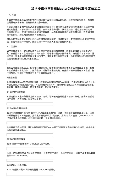
浅谈多面体零件在MasterCAM中的五轴定位加工1. 引言多面体零件加工在五轴机床中的应用远大于五轴联动加工的应用。
这类零件比较常见,共同特征是具有多个平面,且各面的法线各不相同。
针对此类零件采用三轴CNC机床球刀插补铣削或设计相应的夹具完成对应的角度转换的加工案例比比皆是。
对于五轴CNC机床而言,由于机床自身增加了两个旋转轴,通过主轴的摆动或工件的相对转动,使得主轴轴线与被加工面垂直,从而多面体零件的加工化繁为简,在大幅提高效率的同时,加工精度也得到有效的保证。
那么选用五轴机床之后所对应的加工程序如何编制呢,很多朋友还一直保持在3轴机床加工的做法,即每个面编一个程序,然后在程序中手动加入事先计算好的角度。
2. 工艺分析如下所演示工件,完全可以用三轴机床加工所有槽和形腔特征,前提是要提前设计制造好夹具,由此拉长了工艺准备时间;同时在加工过程中还要多次翻转装夹,由此拉长了单件加工循环工时;在多次的重复定位误差的作用下,复映了零件的加工误差。
为此在有5轴CNC的条件下优先考虑使用5轴CNC机床来加工。
而在五轴或四轴机床上,配合相应的旋转轴,使得主轴从始至终垂直于工件被加工平面,其根本实质就是一个定位加工,因为在加工时旋转轴是锁定的,在完成一面平面特征加工之后,旋转轴解锁,转到下一角度进行下一平面的加工循环。
3.数控编程数控编程采用MASTERCAM 2017,在高版本的MASTERCAM 软件,已很好的和强大的设计软件SOLIDWORKS集成在一起,可以方便的转换文件,同时MASTERCAM具体强大的五轴加工,后处理,程序输出功能,可谓宝刀未老,用之游刃有余。
3.1 CAM中选择机床五轴定位加工是一种最常见的五轴加工方式,这种策略使用的是三轴加工策略,无需五轴联动加工设定,打开图形。
选择五轴机床。
3.2 CAM中创建坐标系启动“视图管理器”(VIEW 菜单下- PLANES工具命令),创建一个倾斜平面的局部坐标系,该坐标系最好放在工件的表面,并设定平面的法线为Z的正向。
(计算机辅助制造MasterCAM教学课件)五轴联动加工实验辅导
2.实验目的
五轴联动数控机床系统是解决叶轮、叶片、船用 螺旋桨、重型发电机转子、汽轮机转子、大型柴油机 曲轴等加工的唯一手段。五轴联动数控机床系统对一 个国家的航空、航天、军事、科研、精密器械、高精 医疗设备等行业,有着举足轻重的影响力。
通过本实验,可使学生 1.学习复杂零件数字化制造的相关知识,提高 工程实践能力。 2.学习五轴联动数控机床的原理及加工方法, 拓展学生数控加工技术的实践空间。
42
12. 学生作品
43
13. 参考资料
1.全荣.五坐标联动数控技术 [M].长沙:湖南科 学技术出版社,1995
2.苟琪. MasterCAM五轴加工方法 [M].北京:机 械工业出版社, 2005
3.宋放之《数控机床多轴加工技术实用教程》, 清华大学出版社、2010年
4.马武等.浅析五轴加工中心数控编程技巧[J].制 造技术与机床.2009,(2):165-167.
叶片五轴加工 实验辅导
机械学院教学实验中心 徐学武
2010年12月17日
1
一.五轴联动加工基础
1.五轴加工的特点
(1)提高加工质量:端铣刀五坐标数控加工的断面残留高度小于 球头刀三坐标数控加工的断面残留高度.
2
1.五轴加工的特点
(2)提高加工效率:在相同的表面质量要求下,即相同的h值 下,五坐标数控加工比三坐标数控加工可以采用大很多的 行距s,因而有更高的加工效率.
(3)刀具参数 (4)多轴加工参数 (5)多曲面五轴参数
39
10.叶片的CAM加工
(6)生成刀具路径
40
10.叶片的CAM加工
(7)模拟验证 (8)后处理生成加工程序
41
11.小结
Cimatron13五轴数控加工实用教程最新精品课件-第一章课件ppt

2、五轴定位加工策略和工艺: 包括:环绕铣削、体积插铣、曲面斜率控制加工、3D螺旋加工、清根铣等,见教材p3页的介绍 了解在Cimatron软件编程环境下实现“3+2”定位加工方式,具体见教材p3页的介绍。
第一章 Cimatron5轴加工简介
第二节 五轴加工概述
2、五轴联动加工策略和工艺: 包括:多轴平行切削、多轴垂直曲线铣、多轴两曲线仿形铣、多轴曲线投影铣、多轴两曲面仿形
铣、多轴平行曲面铣、多轴裁剪加工、多轴曲面自动倾斜加工、多轴流线铣等,具体描述见教材p4-p6 的介绍。
第一章 Cimatron5轴加工简介
第三节 五轴加工应用领域
包括以下领域: 具体实例见教材p7-p8页的介绍。 • 航空航天 • 民用消费产品 • 汽车制造 • 造船业 • 医疗行业 • 工模具行业
典型零件如下:
第一章 Cimatron5轴加工简介
Cimatron5轴加工模块介绍:
• 通用五轴联动加工功能和应用场合:
此模块包含了上面的五轴定位加工模块功能,额外提供五轴联动加工策略,可以进行五个轴同时 联动加工,此模块具有自动倾斜功能,自动避让刀具和工件的干涉,可以对带有复杂曲面的零件编程, 支持市面所有五轴加工中心的编程。
此模块最典的应用是在模具上,零件如图所示。
第一章 Cimatron5轴加工简介
Cimatron5轴加工模块介绍:
• 高端五轴加工模块功能和应用场合:
此模块包括了上面两个模块的所有功能,另外增加了五轴加工和五轴应用两个加工策略,是更高级 的模块,此模块还提供专门针对叶轮和弯管等的加工策略,对零件进行五轴粗加工、五轴精加工编程 效率会更高、更安全,主要用于加工更复杂的产品。
第一章 Cimatron5轴加工简介
mastercam五轴加工教程
Additional tool axis control options
Axis Limits
Roughing Options
Multiple depths and passes options
Curve 5 axis
Depth cuts
Multiple depths
A9. Curve 5axis multiple depths.MCX
Swarf 5 axis
Walls are defined by the green surfaces. A plane controls the tool tip
Swarf 5 axis
Swarf 5 axis
Swarf 5 axis walls chains.MCX
Swarf 5 axis
Drill 5 axis
Rotary 4 axis
Rotary 4ax normal to surface.MCX
Rotary 4 axis
Rotary 4 axis
Rotary 4 axis
Rotary 4 axis through point.MCX
Rotary 4 axis
Use center point
Roughing options
Tool axis control Lines Multiple depths
Swarf 5 axis / cut control
Cut control Tool axis control
Tip control
Swarf 5 axis
Swarf 5 axis walls surfaces.MCX
Curve 5 axis
Tool axis control Chain / Step along whole chain
MasterCam 5 axis
MasterCam 5 AxisCurve5axDrill5axSwarf5axMsurf5axFlow5axRotary4ax曲线五轴:对曲面曲线进行五轴曲线加工。
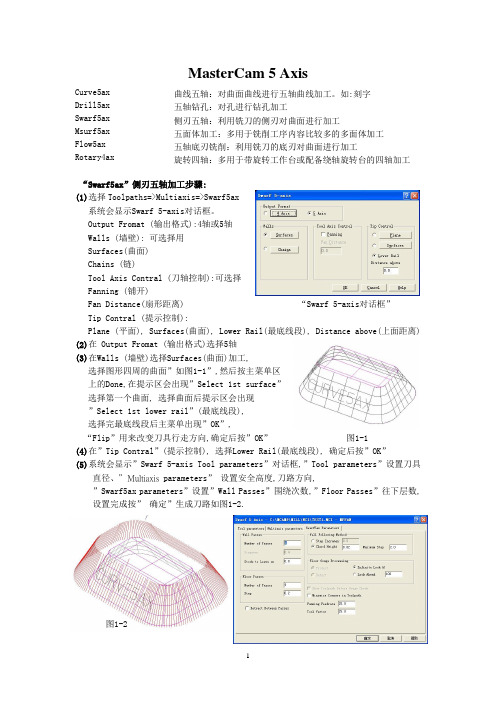
如:刻字 五轴钻孔:对孔进行钻孔加工 侧刃五轴:利用铣刀的侧刃对曲面进行加工 五面体加工:多用于铣削工序内容比较多的多面体加工 五轴底刃铣削:利用铣刀的底刃对曲面进行加工 旋转四轴:多用于带旋转工作台或配备绕轴旋转台的四轴加工“Swarf5ax”侧刃五轴加工步骤:(1)选择Toolpaths=>Multiaxis=>Swarf5ax系统会显示Swarf 5-axis 对话框。
Output Fromat (输出格式):4轴或5轴Walls (墙壁): 可选择用Surfaces(曲面)Chains (链)Tool Axis Contral (刀轴控制):可选择Fanning (铺开)Fan Distance(扇形距离) “Swarf 5-axis 对话框” Tip Contral (提示控制):Plane (平面), Surfaces(曲面), Lower Rail(最底线段), Distance above(上面距离)(2)在 Output Fromat (输出格式)选择5轴(3)在Walls (墙壁)选择Surfaces(曲面)加工,选择图形四周的曲面”如图1-1”,然后按主菜单区上的Done,在提示区会出现”Select 1st surface”选择第一个曲面, 选择曲面后提示区会出现”Select 1st lower rail”(最底线段),选择完最底线段后主菜单出现”OK”,“Flip”用来改变刀具行走方向,确定后按”OK” 图1-1(4)在”Tip Contral ”(提示控制), 选择Lower Rail(最底线段), 确定后按”OK”(5)系统会显示”Swarf 5-axis Tool parameters”对话框,”Tool parameters”设置刀具直径、”Multiaxis parameters” 设置安全高度,刀路方向,”Swarf5ax parameters”设置”Wall Passes”围绕次数,”Floor Passes”往下层数, 设置完成按” 确定”生成刀路如图1-2.图1-2“Curve5ax”曲线五轴加工步骤:(1)选择Toolpaths=>Multiaxis=> Curve5ax系统会显示Curve 5-axis对话框。
WorkNC自动3轴转5轴加工
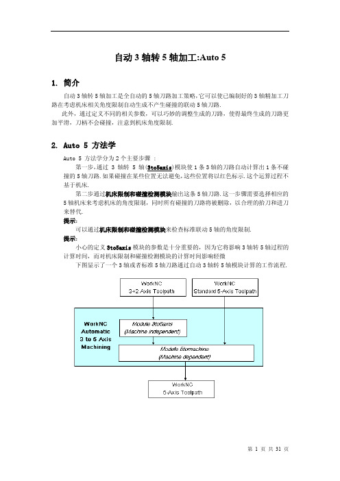
自动3轴转5轴加工:Auto 51.简介自动3轴转5轴加工是全自动的5轴刀路加工策略,它可以使已编制好的3轴精加工刀路在考虑机床相关角度限制自动生成不产生碰撞的联动5轴刀路.此外,通过定义不同的相关参数,可以巧妙的调整生成的刀路,使得最终生成的刀路更加平滑,刀柄不会碰撞,注意到机床角度限制.2.Auto 5 方法学Auto 5 方法学分为2个主要步骤 :第一步,通过 3 轴转 5 轴(3to5axis)模块使1条3轴的刀路自动计算出1条不碰撞的5轴刀路.如果碰撞在某些位置无法避免,这些位置将以红色标示.这个运算过程不基于机床.第二步通过机床限制和碰撞检测模块输出这条5轴刀路.这一步骤需要选择相应的5轴机床来考虑机床的角度限制,同时所有碰撞的刀路将被删除,以合理的抬刀和进刀来替代.提示:可以通过机床限制和碰撞检测模块来检查标准联动5轴的角度限制.提示:小心的定义3to5axis模块的参数是十分重要的,因为它将影响3轴转5轴过程的计算时间,而对机床限制和碰撞检测模块的计算时间影响轻微下图显示了一个3轴或者标准5轴刀路通过自动3轴转5轴模块计算的工作流程.3.Auto-5 用户界面3.1.简介Auto-5 用户界面通过特殊功能菜单打开用户界面图例:此Auto 5模块用户界面包含3大区域:3.1.1.刀路列表窗口刀路列表窗口,在显示当前工作目录的标题栏的下方,包含了所有的刀路和相关信息.此区域显示的信息涉及到刀路序号,刀路类型,刀具的详细信息,3轴的状态(C+/-),3转5轴的状态(5x+/-),机床限制和碰撞检测状态(5m+/-)和注解区域.H(刀柄)列意味着刀柄是否有效的被定义了,如果缺少定义直接计算将会显示错误信息.提示:在Auto 5的计算之前对于相关刀路必须设定刀柄,哪怕碰撞检测不需要计算.此图标所在列提供了Auto 5计算后的刀长信息.如果计算后显示的刀具拔长与WorKNC 刀柄碰撞检测模块内定义的一致并且以黑色表示,那么当前刀具不会发生碰撞.如果,显示的刀具拔长比WorKNC 刀柄碰撞检测模块内定义的长度要长,并且以红色表示,那么原先的长度将会发生碰撞,计算出来的数值既是此刀具最短安全刀长.上图中的当前在窗口内选中的刀路显示了刀路的序号,类型,以及使用的加工视角.这个加工角度是参照加工坐标的加工视角的Z向.Extra 按钮可以打开一个额外的参数设定对话框,用于计算过程.3.1.2.3to5Axis和机床限制和碰撞检测模块参数其余的 WorkNC Auto 5 用户界面是关于 3 to 5 Axis 加工策略和机床限制和碰撞检测模块参数.◆ 3 To 5 Axis加工策略和选项参数提供了8种加工策略适用于 3 to 5 axis 刀路转化.点击窗口左侧的加工策略,相对应的图片伴随显示.选择特定的加工策略将会激活相关的参数选项并且伴随显示相关的图示,如上图所示. 这些不同类型的加工策略及相关参数将会在接下来的文章内详细解释.◆机床限制和碰撞检测模块参数通过选择指定的机床来运算 3 to 5 axis 刀路或者标准联动5-axis 刀路在指定机床内的角度限制. 机床限制和碰撞检测模块的详细信息将会在接下来的文章内详细解释.3.2. 3to5Axis 加工策略3.2.1. 3to5axis 模块内提供了8种不同类型的加工策略.提示:这点注意事项是非常重要的,所有的这些加工策略在运算过程中起到的是驱动的作用.如果在使用相应的加工策略计算中发生刀具或者刀柄的碰撞,软件将自动避让到安全的位置.如果特定的安全位置找不到,那么这些碰撞的点位将会以红色圆圈标示为碰撞点,用户能够通过VisuNC 的图形界面查看.保持垂直 与参考轴角度固定 曲面法向角度跟随 固定角度(吸引) 固定角度(排斥)引导排斥引导(吸引)VisuNC 刀路显示举例,干涉的点位以红色圆圈表示.避免碰撞是非常复杂和消耗时间的一个过程.正确的准备,通过定义合适的加工策略和参数可以提升计算速度.举例来说,如果加工一个垂直壁使用与平面尽可能保持垂直的加工策略,每一个点位都会发生碰撞,计算过程中就将对每一个点位做若干测试来避免碰撞,这就将耗费一定的时间.那么如果在计算之前选择固定角度的加工策略,那么计算速度将极大加快.A.Vertical(保持垂直)此加工策略意味着刀具尽可能与加工视角垂直,除非发生碰撞刀具才会偏离垂直位置一定角度来避让碰撞,当刀路移动到不发生碰撞的位置,刀具再次保持垂直.这种加工策略比较典型的应用于加工工件大部分区域采用较短的刀具保持垂直状态加工,剩余较少的有潜在的刀柄碰撞的区域采用偏置刀具角度加工.在位置(1)刀具轴发生倾斜,因为此处加工垂直壁.举例:如下图示:一条 5-axis 刀路沿着波浪起伏的立壁加工.为了避让碰撞,刀具轴需要倾斜,当条件允许,刀具会回复到更接近于垂直的位置.B.Constant to Axis(与参考轴角度固定)在此加工策略中,刀具轴与加工视角Z向始终保持一个固定的角度.此加工策略特别适用于等高加工的刀路,在加工过程中,A轴或B轴保持固定.此图显示了一条等高加工的刀路在切屑型芯时通过设定固定的角度来做5轴联动加工.C.Normal to Surface(曲面法向)这个加工策略意味着刀具轴在刀路点位的矢量方向始终沿着曲面的法向.但是由于改变相关的参数能够使刀具轴偏离曲面法向,使得这个加工策略的通用性更强.这个加工策略如果加工陡的或者垂直的面(比如使用等高加工)可以设定角度来控制A轴或B轴尽可能固定.如果加工比较浅的凹凸曲面(比如使用投影加工)可以使用完全的法向加工.举例 1:下图显示了一条完全法向加工的刀路,由于工件形状引起刀具轴摆动过多.举例 2:下图工件与上图一致,但是这次把刀具轴最大摆动角度限制在了45°.提示:保持垂直和与参考轴角度固定这2个加工策略是从曲面法向变化而来.通过特定方式定义曲面法向的参数可以得到保持垂直或者与参考轴角度固定的效果.D.No Change(角度跟随)这条加工策略意味着沿着刀路 WorkNC 将尝试保持之前点位的刀具位姿.在凸起的区域,刀具位姿采用曲面法向的方式,在凹的区域刀具位姿保持之前点位的刀具位姿.这条加工策略比较适用于工件的清根加工和凹陷区域的加工.举例:1 曲面法向凸起区域2 其它区域保持同样的刀具轴方向更详细的解释此加工策略:1 曲面法向凸起区域2 其它区域保持同样的刀具轴方向E.Constant (Attractive)[ 固定角度(吸引)]这个加工策略意味着刀具路径上的任意点位,刀具轴参照加工视角的Z向倾斜一个固定角度.刀具轴的方向由吸引点或者吸引曲线的最短距离决定.如果设定多个吸引点,刀具轴将参照多个吸引点的均值分布状态决定. 吸引曲线可以是封闭的或者开放的,同时可以包含多个子曲线.吸引点或者吸引曲线的Z向高度在运算中将被忽略.使用吸引点或者吸引曲线加工策略与 Normal to Surface 比较,刀具轴方向永远指向吸引元素,可以减少刀具轴摆动,切屑更稳定.这个加工策略适用于腔体陡峭曲面以及不规则变化几何形体的等高加工.举例:下面的2幅图片显示了加工半球形腔体使用中间的吸引点和中心左侧的吸引点的差异.下面的2幅图片显示了开放式曲线和封闭式曲线加工复杂腔体的差异.可以同时定义多个吸引点.对于刀路上的点位,刀具轴方向被最接近的吸引点影响最大.下面的2幅图片显示一条通过3个吸引点或2条开放式吸引曲线计算所得的差异.开放式吸引曲线计算所得的刀路中,刀具轴摆动更小.举例:使用 Constant (Attractive) 加工策略来加工一个瓶底.吸引点设定于瓶子中心,固定倾斜角度设定为30°.F.Constant (Repulsive)角度固定(排斥)这个加工策略工作方式和 Constant (Attractive) 类似除了刀具轴指向排斥点或者排斥曲线的反向.这个加工策略意味着刀具路径上的任意点位,刀具轴参照加工视角的Z向倾斜一个固定角度.刀具轴的方向由排斥点或者排斥曲线的最短距离决定.如果设定多个排斥点,刀具轴将参照多个排斥点的均值分布状态决定. 排斥曲线可以是封闭的或者开放的,同时可以包含多个子曲线.排斥点或者排斥曲线的Z 向高度在运算中将被忽略.这个加工策略适用于型芯或凸模以及不规则变化几何形体的等高加工.举例:下面2幅图片显示了半椭圆形型芯,通过排斥点和封闭的排斥曲线计算所得的刀路.(1).接下来这幅图片显示了对于更复杂的形状,通过一条开放式的排斥曲线计算所得的刀路. (1)紧接着的图片显示了加工半球形凸起的工件采用了中心点作为排斥点,并且设定了固定刀具倾斜角度20°的刀路.紧接着的例子显示了一个立于平面上的倾斜圆锥.圆锥顶点设定为排斥点,同时设定刀具轴固定倾斜角度为20°,参照轴为加工坐标Z轴,以此保证 A/B 摆动轴保持固定.G.Guide (Attractive)[ 引导(吸引)]这个加工策略意味着刀路上任意刀位点的刀具轴向由引导点或引导曲线吸引决定.刀具轴心通过引导点或引导曲线.引导曲线可以是开放式的并且可以包含多条子曲线.引导点或引导曲线定义的空间位置需要正确,如果太接近于工件刀具轴变动将加大,如果太远离工件加工效果接近于 constant attractive 加工策略.这个加工策略多用于需要独立加工轴方向的加工(刀具轴缓慢摆动).举例:半圆形的引导曲线 C 在工件的上部H.Guide (Repulsive)[ 引导(排斥)]这个加工策略意味着刀路上任意刀位点的刀具轴向由引导点或引导曲线排斥决定.刀具轴心通过引导点或引导曲线.引导曲线可以是开放式的并且可以包含多条子曲线.引导点或引导曲线定义的空间位置需要正确,如果太接近于工件刀具轴变动将加大,如果太远离工件加工效果接近于 constant repulsive 加工策略.这个加工策略多用于需要独立加工轴方向的加工(刀具轴缓慢摆动).举例:P 点为排斥点3.3.加工策略相关参数选项3.3.1.简介随加工策略而定的参数功能选项位于3 to 5 axis 界面的右侧标准参数列表显示于此区域的左侧.参数根据所选择的加工策略可选择或不可选择 (上图中显示的是 Normal to Surface加工策略的标准参数功能选项).右侧利用图表来表示可选择的参数含义.3.3.2.加工轴/视角轴以加工坐标系或者加工视角坐标系作为参考坐标系.所有角度设定值将以选择的参考坐标系来计算.举例:左侧的第一幅图,加工坐标作为参考坐标.第二副图是以加工视角的Z向作为参考坐标.第一幅图, 加工坐标作为参考坐标.角度 P (固定角度)是25°,从加工坐标开始计算,并且参考坐标永远保持垂直.第二幅图涉及加工视角,此图中加工视角与加工坐标Z轴夹角为55°.角度 P 仍然设定25°,但是因为参考了加工视角的Z向, P 角度相对于加工坐标Z轴为80°.下一图显示了另一种情况.如上图例,刀路通过55°的加工视角建立,但是加工坐标Z轴设定为参考坐标.这意味着所有设定的角度将以加工坐标为参考而不是以视角的Z轴为参考.使用这种方式特别适合加工倒扣的曲面.刀路通过建立视角加工, 然后加工坐标设定为参考坐标,此时 A 或 B 轴可以以固定角度来加工,避免A或B轴的摆动.下图的截屏显示了倒扣曲面以55°的视角加工.参考坐标为加工坐标的Z 轴,设定固定角度为55°,此状态下避免A或B轴的摆动.3.3.3.最大垂直角度曲面上刀位点的刀具轴矢量方向与参照坐标的夹角小于设定的最大垂直角度,此时刀具轴矢量方向指定为垂直.下面2幅图片阐明了这个参数的用法.最大垂直角度 V 设定为10°和30°的情况3.3.4.最小和最大法向角度◆最小法向角度(M)如果刀路上的刀位点法向角度小于最小法向角度 M ,但是大于最大垂直角度 V ,此时刀具轴角度设定为 M .◆最大法向角度(N)如果刀路上的刀位点法向角度小于最大法向角度 N ,但是大于最小法向角度 M ,此时刀具轴角度设定为曲面法向角度.如果角度大于最大法向角度 N ,此时刀具轴角度设定为 N.下面2幅图片阐明了最小和最大法向角度这个参数的用法.(M + N).最小法向角度 (M) of 20°和40°. 最大法向角度 (N) 2例中都设定为60°.如果最小 (M) 和最大 (N) 法向角度定义为相同的数值,就可以得到固定角度的效果.除了平面区域角度为垂直.这就是与参考轴角度固定加工策略的工作原理.下图阐述了这点.最小 (M) 和最大 (N) 法向角度都设为45°,得到 constant axis 角度.注释:设定V = M = N = 0等同Vertical加工策略3.3.5.固定角度对于与参考轴角度固定, 固定角度(吸引)和固定角度(排斥)加工策略,参照加工坐标或者视角坐标定义固定角度 P .另外,固定角度(吸引)和固定角度(排斥)可以使用最大垂直角度 V.下图阐述了固定角度 (P) 参数的使用.与参考轴角度固定加工策略,固定角度P = 25°固定角度(吸引)和固定角度(排斥)加工策略固定角度P = 25°3.3.6.最大摆动角度3to5axis模块计算过程被最大允许角度 (A)限制. 5-axis 的刀路,刀具轴角度将不会超过最大允许角度 (A).如果碰撞处只有通过更大的角度来避让,相应的点位将被标示出来,并且通过 5tomachine模块自动删除相应点位.3.3.7.前倾角选择正的前倾角意味着刀具轴在刀路运动方向前倾,起到优化切削条件,延长刀具寿命的作用.下图阐释了这个参数.同样的刀路分别设定前倾角为0°和15°.3.4.附加参数设定附加参数,通常使用频率较低,通过点击Extra… 按钮打开参数页面.接下来详细解释3个页面.3.4.1.常规页面◆碰撞避让考虑刀柄碰撞避让计算是非常复杂和消耗时间的,依据刀柄的大小.对于此,用户可以决定对于特定区域考虑碰撞时的刀柄的计算方式.a)刀柄和主轴刀柄和主轴完全装配好后进行碰撞避让计算.b)刀柄仅仅计算刀柄部分的碰撞.假设在3轴刀路的刀柄页面内已经定义好刀柄和主轴,那么此处也只计算刀柄部分的碰撞.c)缩短的刀柄只计算用户定义的刀柄长度.提示:使用这个选项将会带来风险,Auto 5在碰撞检测和避让时只计算用户定义的部分,刀柄的剩余的高端将被忽略.可以尝试选择3个选项,通过右侧的显示窗口来理解刀柄和主轴定义的效果.◆最大角度距离允许在刀路内追加刀位点,以此确保没有2个连续刀位点的刀具轴角度超过此设定的角度.此选项可以应用于 3to5axis 和 5tomachine 模块.a)去处不必要的点如果选择了此选项,直线上的所有刀位点或者相同刀具轴角度的刀位点将被删除.这个选项对于较老的控制器和机床可以保证切削的流畅. 此选项可以应用于3to5axis 和 5tomachine 模块.下面2幅图片阐释了这个参数.包含所有刀位点的刀路不必要的刀位点删除后的刀路3.4.2.特效页面点击特效页面如下图所示显示了4个独立的区域,接下来的部分将会详细描述.a)沿加工方向遵循轴向之前所有解释过的角度都是以考虑参考坐标的,尤其对于角度固定加工策略,它们的目的是保持 A或B 轴在固定位置.选择这个沿加工方向遵循轴向参数可以得到相反的效果,那就是保持 C 轴固定, A或B轴摆动.这个参数对于曲面法向,固定角度(吸引)和固定角度(排斥)3个加工策略有效.接下来举例说明一条精加工刀路沿着曲面法向加工,最大法向角度40°.下面的2幅图片没有使用沿加工方向遵循轴向参数的情况.右图显示了从加工方向的俯视图看,刀具轴法向的偏离.接下来的2幅图片显示了选择沿加工方向遵循轴向参数的效果,此例角度设定0°.右图显示了从加工方向看,刀具轴法向聚集在一个平面内,这个平面由加工方向和加工视角的Z向决定.b)角度固定策略可以选择3个中的任何一个参数应用于所有的固定加工策略, 包括与参考轴角度固定, 固定角度(吸引)和固定角度(排斥).◆遵循固定角度这个是缺省的参数.刀路上的刀位点刀具轴方向尽可能的保持固定角度. 如果有潜在的碰撞,通过刀具轴倾斜来避让,当过了碰撞区域,刀具轴回复到设定的角度.◆遵循之前点位刀具轴角度总是跟随之前点位的刀具轴角度.因此,只要不需要碰撞避让,刀具轴将维持固定角度.◆强制固定角度(4-Axis 加工)如果固定角度不能保持, Auto 5 尝试固定A或B角度来避免碰撞.如果找不到这样一个点位,这个点位将标示为碰撞,然后由5tomachine模块自动删除.最后的刀路将保持A或B 轴角度固定.举例:下例中,工件采用等高加工并且使用Auto 5 的与参考轴角度固定加工策略.下图显示了 A轴或B轴角度使用3个选项的不同效果.参数 1(遵循固定角度)角度变动的最多,因为它尝试以固定角度5度来加工,势必存在许多的刀具轴倾斜来避让碰撞.参数 2(遵循之前点位刀具轴角度)初始角度设定为5度,当遇到碰撞区域,刀具轴倾斜到25度,之后的角度跟随于25度,极大减少了 A或B 轴的摆动.参数 3(强制固定角度)角度设定为30°.在此例中整个工件都可以被30°所加工.然而如果角度设定不是这个,而是偏小,那么碰撞的区域就将被标示出来.c)固定角度(吸引),固定角度(排斥)对于固定角度(吸引)和固定角度(排斥)加工策略,可以优化刀路在接近转向点的过程中的表现.使用这个参数能够看到明显的效果,当刀路从吸引曲线的一侧过度到另一侧时.通常,刀具轴角度跳跃是从一点立即跳跃到另一点,比如从–20°到20°.通过设定固定角度优化距离R参数,可以在这个距离内优化这种突变的角度跳跃现象.越接近跳跃点的刀位点刀具轴法向越是垂直.举例:接下来的例子显示了使用这个参数的优化效果,使用固定角度加工策略,设定角度25°,吸引曲线 T 在U型剖面的中心.左侧第一幅图设定参数值为 0.0.在此情况下,刀具轴尽可能保持25°.刀具轴方向由+25°转化到–25°时发生角度突变跳跃.右侧的第二副图设定参数值 10 mm .一旦在10mm范围内角度渐变转化.d)角度跟随–灵敏度角度跟随加工策略意味着当前点位刀具轴方向跟随之前点位的刀具轴方向.对于长距离的凸起运动,刀路跟随曲面的法向,并且,对于内凹运动将跟随之前的刀具轴.凸起运动灵敏度由此参数控制.灵敏度范围从 Low (lazy)到High (sensitive).举例:下面的表格简要的说明了这个参数对一条等高加工的影响.根据不同的灵敏度数值,我们能够评估固定轴变动的数量.灵敏度值Low Medium High固定轴变动的数量47.3% 41.0% 31.5% 下图显示了等高加工刀路使用 low的效果.3.4.3.机床页面点击机床页面将出现下述菜单.起始角度允许你通过A, B 和C的角度定义来设置机床主轴的初始位置.碰撞控制/避让选择忽略碰撞选项意味着在3 to 5 axis 计算过程中不做碰撞检测.警告!使用这个选项将会导致碰撞.必须在VisuNC详细检测来确保加工安全.4.机床限制和碰撞检测机床限制和碰撞检测模块可以针对2种5轴刀路,包括 3 to 5 axis和标准WorkNC 联动5轴刀路.通过此模块处理输出的刀路都能够确保避让潜在的碰撞,把碰撞的点位删除,以抬刀,进刀替代.用户只需简单的选择相应的刀路.系统针对2类点位分别处理,一种是曲面碰撞点,一种是超出机床角度极限.4.1.曲面碰撞点碰撞区域, 由 3 to 5 axis模块标示, 起源于无法避让的点位.这种情况下机床限制和碰撞检测模块删除这些点位并且通过增加不会碰撞的抬刀和进刀动作把断掉的刀路连接起来.垂直或圆弧进刀的添加依赖于参数的设定.下图阐述了这种碰撞类型的处理方式.初始刀路标示了碰撞点处理后的刀路采用垂直进退刀处理后的刀路采用圆弧进退刀4.2.3to5Axis刀路的机床角度限制管理我们将看一些案例,这些机床C轴或 A/B轴达到极限位置.4.2.1.B轴限制下图显示的机床是DMG的DMU 60T. C轴没有角度限制,但是B轴限制在–12° to +90°.B轴角度限制通过机床角度翻转避免.这意味着机床主轴首先要移动到一个不碰撞的垂直位置,然后C轴设为C=C± 180°,B轴设为 B = -B. 也就是工件随C轴旋转了180°,B轴反响摆动,然后再次加工.4.2.2.A轴限制此例中的机床是Zimmermann的 FZ40. C轴限制在–200° to +200°并且A轴限制范围–95° to +95°.C 轴的角度限制通过机床放松回转360°运动可以解决.由于此机床无法回转360°,只能通过回转180°配合A轴翻转来解决.4.2.3.C轴限制下例显示了机床的C轴限制范围在 -360° to +360°.当到达限制位置,机床限制和碰撞检测模块退回到一个安全的垂直位置并且C轴放松回转360°. 由于垂直轴的坐标定义为 ( 0, 0, 1),它没有代表C轴的角度, 机床限制和碰撞检测模块将把放松回转角度写入5轴刀路.对于指定的机床就可以输出相应的刀路,刀路由机床所决定.放松回转角度的添加在VisuNC内显示,以白色圆圈表示.当机床为了放松回转运动,移动到安全的垂直位置时,抬刀,接近和垂直或圆弧进刀依据刀路参数的设定.接下来的2个例子阐释这点.垂直放松回转运动圆弧放松回转运动4.2.4.预判A/B 轴角度限制通过预判刀路轨迹,可以解决 A/B角度限制.如果机床限制和碰撞检测模块侦测到将要到达 A/B轴的角度限制并且当前位置是垂直的, C轴在到达下一点位前即刻旋转(C = C+180° or C = C –180°). 由于当前位置刀具轴是垂直的(A = B = 0), A/B翻转仍然为 0.这个过程可以让刀路不必抬刀.下图解释了这点.4.2.5.机床角度限制处理同样可以应用于标准的联动5轴刀路机床限制和碰撞检测模块同样可以处理WorkNC 的标准联动5轴刀路.在此情况下 3 To 5 Axis 用户界面将不可使用.4.2.6.保存碰撞点于子刀路3 to 5 axis标示出来的碰撞点或者通过机床限制和碰撞检测模块剪切掉的刀路可以保存为一个子刀路.但是保存碰撞部分的刀路一定要遵循下述规则.1)在WorkNC定义刀路 (比如. number 10).2)指定刀柄并且选择保存干涉和不干涉部分的选项(子刀路 10.1 建立).3)计算刀路,刀柄和子刀路.4)打开Auto-5 界面并且选择 3 to 5 axis的加工策略和机床限制和碰撞检测模块参数(number 10主刀路).5)在机床限制和碰撞检测参数设定区域选择保存碰撞区域和非碰撞区域. 对(10.1)不要指定任何参数或选项.6)开始计算.7)通过对主刀路(no.10)机床限制和碰撞检测的计算,子刀路(10.1)将保存原始的标准的3轴刀路碰撞部分.提示:3 to 5 axis模块永远针对未分割前的最初始的3轴刀路计算举例:下例中显示了之前刀路(no.10)详细的步骤和结果.原始刀路 no. 10 刀路no.10 刀柄碰撞检测后–未使用 3 to5 axis 模块刀路no.10 经过3 to5 axis 模块计算刀路no.10经过机床限制和碰撞检测计算。
- 1、下载文档前请自行甄别文档内容的完整性,平台不提供额外的编辑、内容补充、找答案等附加服务。
- 2、"仅部分预览"的文档,不可在线预览部分如存在完整性等问题,可反馈申请退款(可完整预览的文档不适用该条件!)。
- 3、如文档侵犯您的权益,请联系客服反馈,我们会尽快为您处理(人工客服工作时间:9:00-18:30)。
Roughing options
Tool axis control Lines M cut control
Cut control Tool axis control
Tip control
Swarf 5 axis
Swarf 5 axis walls surfaces.MCX
Lead / Lag - Side tilt
OP10 side tilt.MCX
Additional tool axis control options Axis limits
A8. Curve 5 axis using axis limits.MCX
Additional tool axis control options
Axis limits: limit or lock an axis vector
Point Generators
Point Generators add vectors based on change in vector angle or distance between vectors
Point Generators
Angle Distance
Lead / Lag: adjusts tool axis vector forward or backward relative to the cut direction Side tilt: adjusts tool axis vector left or right relative to the cut direction
Swarf 5 axis
Walls are defined by the green surfaces. A plane controls the tool tip
Swarf 5 axis
Swarf 5 axis
Swarf 5 axis walls chains.MCX
Swarf 5 axis
Rotary 4 axis
Rotary 4 axis
Rotary 4ax axial.MCX
Rotary 4 axis
Axial cut method
Rotary 4 axis
ModuleWorks multi-axis interface
Cut control Tool axis control
TOOL AXIS CONTROL
How is the tool axis controlled?
TOOL TIP CONTROL
What controls the depth of the tool?
CNC Software’s multi-axis interface
Curve 5 axis
Curve 5 axis
Curve 5 axis
A2. Tool axis control surface.MCX
Curve 5 axis
Tool axis control Surface. All vectors are normal to the defined tool axis control surface
Curve 5 axis
Tool axis control From Point
Curve 5 axis
A5. Tool axis control to point.MCX
Curve 5 axis
Tool axis control To Point
Curve 5 axis
A6. Tool axis control chain.MCX
Swarf 5 axis
Swarf 5 axis
Flow 5 axis and Port 5 axis / cut control
Drives the tool along the XY or UV surface data
Cut control
Cut control - Tool axis control - Tip control
Point Generators
A7. Curve5ax using point generators.MCX
Additional tool axis control options
Lead / Lag - Side tilt
OP10 side tilt.MCX
Additional tool axis control options
Drill 5 axis
Rotary 4 axis
Rotary 4ax normal to surface.MCX
Rotary 4 axis
Rotary 4 axis
Rotary 4 axis
Rotary 4 axis through point.MCX
Rotary 4 axis
Use center point
Tool axis control
Curve 5 axis
A1. Tool axis control lines.MCX
Curve 5 axis
Tool axis control lines. Selection order doesn’t matter, Direction does. Vector direction should point toward the tool holder
Axis Limits
Axis Limits
Think of the limiting area as 0 and 10 degree lines rotated around the Z axis creating cone surfaces. The axis is relative to world coordinates.
Flow 5 axis
OP 10 Flow 5axis.MCX
Msurf 5ax
Msurf5ax cut pattern cylinder.MCX
Msurf 5 axis / cut control
Use a surface or defined primitive surface to calculate the flow of tool motion.
Curve 5 axis
Tool axis control Chain / Step along whole chain
Additional tool axis control options
Point generators: adds tool axis vectors based on an incremental distance or angle
Cut control -
Tool axis control -
Tip control
Drill 5 axis
Drill 5 axis points and lines.MCX
Drill 5 axis
Entity Type: Points and Lines define drill location and tool axis
Cut Control / Morph between 2 curves
This option will create a morphed tool path between two leading curves. Morphed means that the generated tool path is approximated between the tilt curves and evenly spread over the surface. This option is very suitable to machine steep areas for mould making.
Walls are defined using lower and upper chains Tool tip is controlled by surfaces
Swarf 5 axis
Swarf 5 axis tip control lower rail.MCX
Swarf 5 axis
Tip control uses the lower rail
Additional tool axis control options
Axis Limits
Roughing Options
Multiple depths and passes options
Curve 5 axis
Depth cuts
Multiple depths
A9. Curve 5axis multiple depths.MCX
Angle: If active, additional tool axis vectors are generated between tool axis vectors if they change more than the angle specified here. Distance: If active, additional tool axis vectors are generated between tool axis vectors which have a distance greater than the distance specified here
Cut control - Tool axis control - Tip control
Msurf 5 axis
Cut Pattern: Cylinder
Msurf 5 axis
Depth cut parameters
Msurf 5 axis
Drill 5 axis / cut control
Cut Control / Cuts along curve