Cyclone II系列FPGA配置手册
Cyclone II器件中文资料
一、外文资料译文:Cyclone II器件系列简介关键词:cyclone II器件;特点;简介;在非常成功的第一代Cyclone器件系列之后,Altera的Cyclone II FPGA系列扩大低成本的FPGA的密度,最多达68,416个逻辑单元(LE),提供622个可用的输入/输出引脚和1.1M比特的嵌入式寄存器。
Cyclone II器件的制造基于300毫米晶圆,采用台积电90nm、低K值电介质工艺,这种工艺技术是使用低绝缘体过程以确保了快速有效性和低成本。
通过使硅片面积最小化,Cyclone II器件可以在单芯片上支持复杂的数字系统,而在成本上则可以和ASIC竞争。
不像其他用电力功耗和性能来换取低成本的FPGA卖主,Altera 最新一代低价位的FPGA——cyclone II FPGA系列,和同类90nmFPGA器件相比,它提高了百分之六十的性能和降低了一半的功耗。
低成本和优化特征使Cyclone II FPGA系列为各种各样的汽车、消费、通讯、视频处理、测试与测量、和其他最终市场提供理想的解决方案。
在参考设计、系统图,和IP,使用cyclone II FPGA系列可以帮助你迅速实现最总市场方案开发。
低成本的嵌入式解决方案Cyclone II 器件支持Nio s II 嵌入式处理器,能够自己完成自定义的嵌入式处理器。
Cyclone II器件还能够扩展各种外部存储器和I/O口或者嵌入式处理器的性能。
单个或多个NiosII嵌入式系统中嵌入式处理器也可以设计成cyclone II设备以提供一些额外的同时处理的能力或者甚至取代已经在你的系统中存在的嵌入式处理器。
使用cyclone II和nios II 能够拥有成本低和高性能处理方案的共同特点,和普通的产品相比,这个特点能够延长你的产品的生命周期,提高产品进入市场的时间。
低成本DSP方案单独使用cycloneII FPGA 系列或者或者作为数字信号处理(DSP)协处理器以提高数字信号处理(DSP)应用的性价比。
嵌入式开发笔记——MCU配置Altera-Cyclone系列FPGA

嵌入式开发笔记——MCU配置Altera-Cyclone系列FPGA作者:zzssdd2E-mail:*******************1、需求描述FPGA内部是SRAM储存结构,掉电后程序就会丢失,故需要将FPGA程序保存在掉电不丢失的储存介质中(比如FLASH、EMMC、SD卡等),在每次上电时读取程序进行配置。
2、功能分析项目中使用的FPGA型号是Altera公司(现属于Intel)的Cyclone系列。
在Altera的文档《Cyclone Device Handbook,Volume1》的第13章节讲述了该系列FPGA的几种配置方式。
FPGA'的三种配置模式模式描述AS(Active serial)模式FPGA主动配置。
该模式由FPGA主动从外部储存器读取配置数据PS(Passive serial)模式FPGA被动控制。
该模式由外部控制器对FPGA进行配置JTAG模式通过外部下载器下载到FPGA内部SRAM中FPGA选择配置模式通过MSEL0和MSEL1引脚不同的电平来选择配置方式(如果使用JTAG配置则可以忽略这些引脚配置)MSEL1 MSEL0 模式0 0 AS0 1 PSx x JTAG最终确定的方案是使用PS模式通过MCU来升级、配置FPGA。
下面主要讲使用MCU对FPGA进行PS模式下的配置过程。
PS模式配置引脚时序•发起配置请求o nCONFIG引脚拉低tCFG时间然后拉高,等待nSTATU拉低响应请求•进行配置o FPGA在DCLK引脚的上升沿采集DATA引脚Bit数据,LSB在前传输方式•配置完成o等待CONF_DONE引脚回应一个高电平表示配置完成PS配置模式时序参数3、功能实现配置FPGA用到的变量和标志static uint8_t fpga_cfg_buf[W25Q_SECTOR_SIZE]; //储存从FLASH读出数据static __IO uint8_t fpga_cfg_sta = 0x00; //记录配置状态//配置过程用到的标识enum{FPGA_CFG_ENABLE = 0x01,FPGA_CFG_START = 0x02,FPGA_CFG_DONE = 0x04,FPGA_CFG_OVER = 0x08,};MCU与FPGA连接引脚配置/**************************************************************** ******** 函数: fpga_config_init* 功能: 配置FPGA引脚* 输入: 无* 输出: 无*************************************************************** ********/void fpga_config_init(void){GPIO_InitTypeDef GPIO_InitStruct = {0};/* 引脚时钟使能 */FPGA_PIN_CLK_ENABLE();/* nCFG、DAT、CLK配置为输出 */GPIO_InitStruct.Pin = FPGA_nCFG_PIN;GPIO_InitStruct.Mode = GPIO_MODE_OUTPUT_PP;GPIO_InitStruct.Pull = GPIO_NOPULL;GPIO_InitStruct.Speed = GPIO_SPEED_FREQ_HIGH;HAL_GPIO_Init(FPGA_nCFG_PORT, &GPIO_InitStruct);GPIO_InitStruct.Pin = FPGA_DAT_PIN;HAL_GPIO_Init(FPGA_DAT_PORT, &GPIO_InitStruct);GPIO_InitStruct.Pin = FPGA_CLK_PIN;HAL_GPIO_Init(FPGA_CLK_PORT, &GPIO_InitStruct);/* nSTA、CFG_DONE配置为输入 */GPIO_InitStruct.Pin = FPGA_nSTA_PIN;GPIO_InitStruct.Mode = GPIO_MODE_INPUT;GPIO_InitStruct.Pull = GPIO_NOPULL;HAL_GPIO_Init(FPGA_nSTA_PORT, &GPIO_InitStruct);GPIO_InitStruct.Pin = FPGA_CFG_DONE_PIN;HAL_GPIO_Init(FPGA_CFG_DONE_PORT, &GPIO_InitStruct);/* 配置引脚默认状态 */HAL_GPIO_WritePin(FPGA_nCFG_PORT, FPGA_nCFG_PIN, GPIO_PIN_SET);HAL_GPIO_WritePin(FPGA_DAT_PORT, FPGA_DAT_PIN, GPIO_PIN_RESET);HAL_GPIO_WritePin(FPGA_CLK_PORT, FPGA_CLK_PIN, GPIO_PIN_RESET);}MCU对FPGA配置过程/**************************************************************** ******** 函数: fpga_config_process* 功能: FPGA程序配置* 输入: _uiDataSize:FPGA配置文件大小* _uiStartAddr:FLASH储存FPGA配置文件地址* 输出: 失败:< 0; 成功:0*************************************************************** ********/int fpga_config_process(uint32_t _uiDataSize, uint32_t _uiStartAddr){UINT interrupt_save;uint16_t i, j;uint32_t uiTout, uiRdAddr, uiCnt = 0;fpga_cfg_sta = 0;uiRdAddr = _uiStartAddr;/*############## 第一阶段:发起配置请求########################*/FPGA_PinWrite(FPGA_nCFG_PORT,FPGA_nCFG_PIN,GPIO_PI N_RESET);dwt_delay_us(100);FPGA_PinWrite(FPGA_nCFG_PORT,FPGA_nCFG_PIN,GPIO_PI N_SET);dwt_delay_us(40);/* 等待FPGA回应:100ms超时 */for (uiT out = 0; uiT out < 10000; uiTout++){if (GPIO_PIN_RESET == FPGA_PinRead(FPGA_nSTA_PORT,FPGA_nSTA_PIN)){SET_BIT(fpga_cfg_sta, FPGA_CFG_START);break;}dwt_delay_us(10);}/* 是否响应? */if (!READ_BIT(fpga_cfg_sta, FPGA_CFG_START)){return -1;}/*############## 第二阶段:进行配置########################*/do{W25Q_ReadBuffer(fpga_cfg_buf, uiRdAddr, W25Q_SECTOR_SIZE);uiRdAddr += W25Q_SECTOR_SIZE;for (i = 0; i < W25Q_SECTOR_SIZE; i++){/* 按bit写入,LSB在前 */DISABLE_IRQ();for (j = 0; j < 8; j++){if (fpga_cfg_buf[i] & 0x01){FPGA_PinWrite(FPGA_DAT_PORT,FPGA_DAT_PIN,GPIO_PIN_S ET);}else{FPGA_PinWrite(FPGA_DAT_PORT,FPGA_DAT_PIN,GPIO_PIN_ RESET);}FPGA_PinWrite(FPGA_CLK_PORT,FPGA_CLK_PIN,GPIO_PIN_R ESET); Delay(2);FPGA_PinWrite(FPGA_CLK_PORT,FPGA_CLK_PIN,GPIO_PIN_S ET); Delay(2);FPGA_PinWrite(FPGA_CLK_PORT,FPGA_CLK_PIN,GPIO_PIN_R ESET); Delay(2);fpga_cfg_buf[i] >>= 1;ENABLE_IRQ();/* 数据写入完毕退出 */if (++uiCnt >= _uiDataSize){SET_BIT(fpga_cfg_sta, FPGA_CFG_OVER);break;}}}while(RESET == READ_BIT(fpga_cfg_sta, FPGA_CFG_OVER));/*############## 第三阶段:等待配置完成回应########################*/for (i = 0, uiT out = 0; uiTout < 20000; uiTout++){dwt_delay_us(100);if (GPIO_PIN_SET == FPGA_PinRead(FPGA_CFG_DONE_PORT,FPGA_CFG_DONE_PIN)) {if (++i >= 10){SET_BIT(fpga_cfg_sta, FPGA_CFG_DONE);break;}}else{i = 0;}if (READ_BIT(fpga_cfg_sta, FPGA_CFG_DONE)) {return 0;}else{return -1;}}。
FPGA开发板EP1C12用户手册(一版)

使用手册目 录第一章综述 (1)EP1C12核心板资源介绍 (1)FPGA开发板资源介绍 (2)第二章 系统模块功能介绍 (5)EP1C12核心板模块说明EP1C12F324C8芯片说明 (7)NOR FLASH模块说明 (8)SRAM模块说明 (9)FPGA接口I/O说明 (10)调试接口JTAG、AS说明 (11)其它功能模块 (12)EP1C12核心板使用注意事项 (15)FPGA开发平台模块说明液晶显示模块 (17)RTC实时时钟模块 (19)USB接口模块 (19)音频CODEC接口模块 (20)EEPROM存储模块 (21)数字温度传感器模块 (22)其它功能模块 (23)FPGA开发平台使用注意事项 (24)附表一核心板载资源与FPGAEP1C12I/O接口对照表 (25)附表二EP1C12与开发板硬件资源I/O接口对照表 (30)第一章综述FPGA开发来台是根据现代电子发展的方向,集EDA和SOPC系统开发为一体的综合性实验开发系统,除了满足高校专、本科生和研究生的SOPC教学实验开发之外,也是电子设计和电子项目开发的理想工具。
整个开发系统由核心板EP1C12、SOPC开发平台和扩展板构成,根据用户不同的需求配置成不同的开发系统。
EP1C12核心板EP1C12核心板为基于Altera Cyclone器件的嵌入式系统开发提供了一个很好的硬件平台,它可以为开发人员提供以下资源:1主芯片采用Altera Cyclone器件EP1C12F324C82EPCS4I8配置芯片34个用户自定义按键44个用户自定义LED51个七段码LED6标准AS编程接口和JTAG调试接口750MHz高精度时钟源8三个高密度扩展接口9系统上电复位电路10支持+5V直接输入,板上电源管理模块系统主芯片采用324引脚、BGA封装的E1C12 FPGA,它拥有12060个LE,52个M4K 片上RAM(共计239616bits),2个高性能PLL以及多达249个用户自定义IO。
Cyclone II系列FPGA简介

I/O标准 3.3V/2.5V/1.8V LVTTL 3.3V/2.5V/1.8V/1.5V LVCMOS 3.3V PCI 3.3V PCI-X
性能 167MHz 167MHz 66MHz 100MHz
典型应用 通用 通用
PC和嵌入式 PC和嵌入式
2.5V/1.8VSSTLClass I 2.5V/1.8VSSTLClass II 1.8V/1.5V HSTL Class I 1.8V/1.5V HSTL Class II
Cyclone II 系列的IOE结构
a
15
I/O单元模块
Cyclone II器件支持多种单端I/O标准,包括LVTTL 、LVCMOS、SSTL、 HSTL、PCI和PCI-X。单端I/O标准具有比差分I/O标准更强的电流驱动能 力,在同如DDR 和DDR2 SDRAM 等高级存储器器件接口时非常重要。 Cyclone II器件也支持对特定I/O标准的可编程驱动强度控制,设置范围 为2-24mA。下表为Cyclone II器件支持的单端I/O标准和各自的性能。
Cyclone II系列FPGA简介
组员:盛传广 丁宁 徐兴龙 刘鑫 皮少华 柳媛瑾
a
1
Cyclone II系列FPGA简介
Cyclone II系列器件是Altera低成本Cyclone系 列的第二代产品,Cyclone II FPGA的成本比第一代 Cyclone 器件低30%,逻辑容量大3倍多。Cyclone II器件采用TSMC经验证的90nm低K绝缘材料工艺技术, 是业界成本最低的FPGA。Cyclone II通过使用新型 的架构,缩小裸片尺寸,在保证成本优势的前提下提 供了更高的集成度和性能。
167MHz
存储器
CYCLONE II系列FPGA的结构
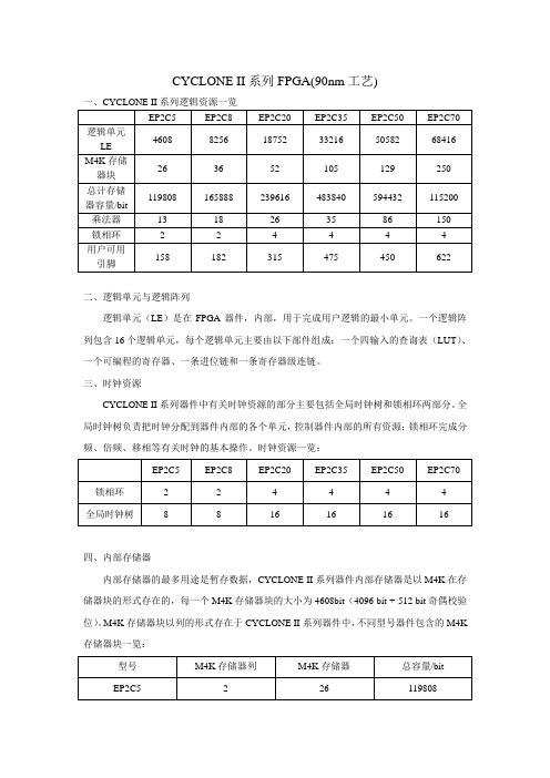
CYCLONE II系列FPGA(90nm工艺)二、逻辑单元与逻辑阵列逻辑单元(LE)是在FPGA器件,内部,用于完成用户逻辑的最小单元。
一个逻辑阵列包含16个逻辑单元,每个逻辑单元主要由以下部件组成:一个四输入的查询表(LUT)、一个可编程的寄存器、一条进位链和一条寄存器级连链。
三、时钟资源CYCLONE II系列器件中有关时钟资源的部分主要包括全局时钟树和锁相环两部分。
全局时钟树负责把时钟分配到器件内部的各个单元,控制器件内部的所有资源;锁相环完成分频、倍频、移相等有关时钟的基本操作。
时钟资源一览:四、内部存储器内部存储器的最多用途是暂存数据,CYCLONE II系列器件内部存储器是以M4K在存储器块的形式存在的,每一个M4K存储器块的大小为4608bit(4096 bit + 512 bit奇偶校验位)。
M4K存储器块以列的形式存在于CYCLONE II系列器件中,不同型号器件包含的M4K 存储器块一览:CYCLONE II 系列器件中的M4K 可以被配置为以下模式:单口模式、简单双口模式、完全双口模式、移位寄存器模式、只读存储器(ROM )模式和先入先出(fifo )模式。
五、FPGA 芯片的配置由于CYCLONE II 系列的FPGA 是基于SRAM 工艺制造的,SRAM 属于易失性的存储媒质,因此FPGA 在每次上电时必须重新配置。
CYCLONE II 系列的FPGA 支持3种配置方式:主动串行(AS )、被动串行(PS )和JATG 模式。
CYCLONE II 器件的配置分为3个阶段:复位阶段、配置阶段和初始化阶段。
六、FPGA 内部资源的使用锁相环(PLL )配置,锁相环一般用于同步输入时钟和输入数据,以及完成时钟综合,包括分频、倍频、移相等操作。
PLL 配置需求:CYCLONE II 系列器件中的M4K 配置为以下模式:单口RAM 模式、移位寄存器模式、只读存储器(ROM )模式和先入先出(fifo )模式。
Cyclone II系列FPGA简介

Cyclone II系列FPGA整体特性
Cyclone II器件容量有4608-68416个逻辑单元, 还具有新的增强特性,包括多达1.1Mbit的嵌入存储 器、多达150个嵌入18×18乘法器、锁相环、支持外 部存储器接口及差分和单端I/O标准。
Cyclone IIห้องสมุดไป่ตู้列的主要特点:
高效率的芯片结构支持从4608LE到68416LE的集成度。 包含内部嵌入式乘法器,支持DSP运算。 先进的I/O,支持PCI,DDR,DDR2等多种接口。 全局时钟管理及嵌入式锁相环。 支持Altera IP Core 及Nios II 嵌入式处理器。
26
2
4
182 315
75
125
EP2C35
33216 105
483840
35 4 475 200
EP2C50
50528 129
594432
86 4 450 192
EP2C70
68416 250
115200
150 4 622 275
4
Cyclone II系列FPGA整体特性
• Cyclone II 系列FPGA 的内部结构示意图
Cyclone II 系列的IOE结构
15
I/O单元模块
Cyclone II器件支持多种单端I/O标准,包括LVTTL 、LVCMOS、SSTL、 HSTL、PCI和PCI-X。单端I/O标准具有比差分I/O标准更强的电流驱动能 力,在同如DDR 和DDR2 SDRAM 等高级存储器器件接口时非常重要。 Cyclone II器件也支持对特定I/O标准的可编程驱动强度控制,设置范围 为2-24mA。下表为Cyclone II器件支持的单端I/O标准和各自的性能。
CycloneFPGA配置模式及应用
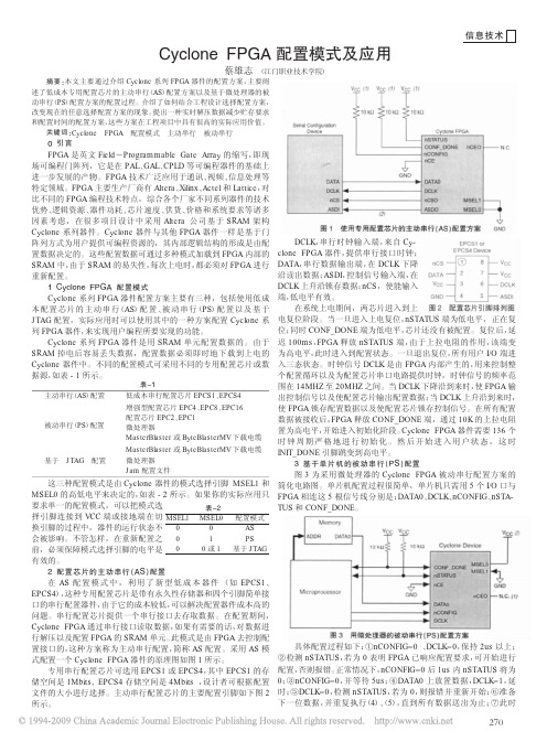
摘要:本文主要通过介绍Cyclone 系列FPGA 器件的配置方案,主要阐述了低成本专用配置芯片的主动串行(AS )配置方案以及基于微处理器的被动串行(PS )配置方案的配置过程。
介绍了如何结合工程设计选择配置方案,改变现在的任意选择配置方案的现象。
提出一种实时解压数据减少贮存要求和配置时间的配置方案,这些方案在工程项目中具有很高的实际应用价值。
关键词:Cyclone FPGA 配置模式主动串行被动串行0引言FPGA 是英文Field -Programmable Gate Array 的缩写,即现场可编程门阵列,它是在PAL 、GAL 、CPLD 等可编程器件的基础上进一步发展的产物。
FPGA 技术广泛应用于通讯、视频、信息处理等特定领域。
FPGA 主要生产厂商有Altera 、Xilinx 、Actel 和Lattice ,对比不同的FPGA 编程技术特点,综合各个厂家不同系列器件的技术优势、逻辑资源、器件功耗、芯片速度、供货、价格和系统要求等诸多因素考虑,在很多项目设计中采用Altera 公司基于SRAM 架构Cyclone 系列器件。
Cyclone 器件与其他FPGA 器件一样是基于门阵列方式为用户提供可编程资源的,其内部逻辑结构的形成是由配置数据决定的。
这些配置数据可通过多种模式加载到FPGA 内部的SRAM 中,由于SRAM 的易失性,每次上电时,都必须对FPGA 进行重新配置。
1Cyclone FPGA 配置模式Cyclone 系列FPGA 器件配置方案主要有三种,包括使用低成本配置芯片的主动串行(AS )配置、被动串行(PS )配置以及基于JTAG 配置,实际应用时可以使用其中的一种方案配置Cyclone 系列FPGA 器件,来实现用户编程所要实现的功能。
Cyclone 系列FPGA 器件是用SRAM 单元配置数据的。
由于SRAM 掉电后容易丢失数据,配置数据必须即时地下载到上电的Cyclone 器件中。
CYCLONE II系列FPGA存储器模块

CYCLONE II系列FPGA存储器模块○1CYCLONE II 系列FPGA支持的双口RAM 类型:●单端口RAM●简单双端口RAM●真双端口RAM【在QUARTUS II中的库模块是AltSYNCRam】●混合真双端口RAM【允许不同读写宽度】○2CYCLONE II 系列FPGA存储器模块M4K寄存器清零的三种方法:●使用【异步】清零信号aclr●上电复位器件●assert the device-wide reset signal using the DEV_CLRn option○3地址时钟使能应用于:●高速缓冲储存●地址使能默认为【低】电平●读地址时钟使能时:读地址锁存在使能时的地址上,读出的数据就是锁定的那个地址单元的数据。
如:读地址锁存在0x05地址,则读出的数据就是0x05地址里面的数据值。
●Figure 8–3 shows an address clock enable block diagram. The address register output is fedback to its input via a multiplexer. The multiplexer output is selected by the address clock enable (addressstall) signal. Address latching is enabled when the addressstall signal goes high (active high). The output of the address register is then continuously fed into the input of the register until the addressstall signal goes low.●●●写地址时钟使能时:写入的数据依次写在锁定的地址上。
宝典AlteraCycloneIIFPGA的几种代码配置
Altera Cyclone II FPGA的几种代码配置1、根据FPGA在配置电路中的角色,配置数据可以使用3种方式载入到目标器件中:(1) FPGA主动方式:由FPGA来主动输出控制和同步信号给FPGA的串行配置芯片(EPCS系列),配置芯片收到命令后,把配置数据发给FPGA,完成配置过程;在AS模式下,FPGA必须与AS串行配置芯片配合使用,它与FPGA的接口为四跟信号线,分别为:串行时钟输入(DCLK),AS控制信号输入 (ASDI),片选信号(nCS),串行数据输出(DATA)。
(2) FPGA被动方式:被动模式下,由系统的其他设备发起并控制配置过程,这些设备可以是配置芯片(EPC系列),或者单板的微处理器、CPLD等。
FPGA 在配置过程中完全处于被动地位,只是输出一些状态信号来配合配置过程;在PS模式下,需要配置时钟(DCLK),配置数据(DATA0),配置命令 (nCONFIG),状态信号(nSTATUS),配置完成指示(CONF_DONE)这四个信号来完成配置过程。
(3) JTAG模式:使用JTAG进行配置可以使用Altera的下载电缆,或者通过智能主机模拟JTAG的时序来进行配置;JTAG接口由四个必须的信号TDI、TDO、TMS 和TCK,以及一个可选的TRST构成。
2、若使用ByteBlasterII下载电缆,支持的配置方式有以下3种:AS方式:对AS配置芯片(ECPS系列)进行编程;PS方式:可以对FPGA进行配置;JTAG方式:可以对FPGA、CPLD以及Altera配置芯片(EPC系列)编程。
3、AS及PS模式下的注意事项PS模式:如果你用电缆线配置板上的FPGA芯片,而这个FPGA芯片已经有配置芯片在板上,那你就必须隔离缆线与配置芯片的信号一般平时调试时不会把配置芯片焊上的,这时候用缆线下载程序.只有在调试完成以后,才把程序烧在配置芯片中,然后将芯片焊上.或者配置芯片就是可以方便取下焊上的那种.这样出了问题还可以方便地调试.AS模式下: 用过一块板子用的AS下载,配置芯片一直是焊在板子上的,原来AS方式在用线缆对配置芯片进行下载的时候,会自动禁止对FPGA的配置,而PS 方式需要电路上隔离。
FPGADEV red cyclone 开发板 RCII-CY1C6 12 说明书

Red Cyclone开发板RCII-CY1C6/12 用户手册 Ver 2.2修订历史版本 修订人 修订日期 修订内容0.1 红色飓风 2004年10月15日初始版本0.5 红色飓风 2004年10月17日建立基本框架,补充部分细节0.9 红色飓风 2004年11月02日基本完善1.1 红色飓风 2004年11月20日修订部分管脚2.1 红色飓风 2005年03月17日重新改版,增加了VGA,LCD,PS2和USB 2.1 红色飓风 2005年12月01日修改用户手册2.2 红色飓风 2008年11月修改用户手册目录RED CYCLONE (1)主开发板(RCM).................................................................................................................错误!未定义书签。
用户手册 VER 2.2.. (1)修订历史 (2)内容介绍:本手册包括以下章节 (5)CHAPTER 1主要器件及特性 (6)主要元器件介绍 (6)支持的功能扩展板 (8)开发板示意图 (8)CHAPTER 2 开关、按键与数码管 (9)拨码开关 (9)按键开关 (9)LED S (10)CHAPTER 3 VGA 接口 (12)CRT显示器的工作原理: (13)VGA信号的时序关系: (14)CHAPTER 4 PS/2 鼠标键盘接口 (16)键盘 (17)鼠标 (19)CHAPTER 5 RS-232 串口 (20)串行通信标准 (21)接收机设计 (23)发送机设计 (23)CHAPTER 6 字符型液晶显示器 (24)介绍 (24)FPGA控制原理 (26)CHAPTER 7 USB接口及芯片 (28)CHAPTER 8 用户自定义串行接口 (30)CHAPTER 9 高速异步SRAM (31)CHAPTER 10 高速同步SDRAM (33)CHAPTER 11大容量,快速FLASH (35)CHAPTER 12 扩展板接口 (37)扩展地址总线 (37)扩展数据总线 (38)扩展用户IO (39)说明 (40)CHAPTER 13 JTAG 下载与调试接口 (41)JTAG接口 (41)AS接口 (41)CHAPTER 14 电源分配 (42)CHAPTER 15 复位电路 (44)说明 (44)CHAPTER 16 时钟源 (45)EP1C6和EP1C12的区别 (47)附录A:原理图 (47)附录 B, 主要元件的相关材料 (47)内容介绍:本手册包括以下章节 • Chapter 1, “主要器件及特性”• Chapter 2, “开关、按键与数码管” • Chapter 3, “VGA 接口”• Chapter 4, “PS/2 鼠标/键盘接口” • Chapter 5, “RS-232 串口”• Chapter 6,“字符型液晶显示器接口”• Chapter 7,“USB2.0接口与芯片”Chapter 8,“用户自定义串行接口”• Chapter 9,“高速异步SRAM”• Chapter 10,“高速同步SDRAM”• Chapter 11,“大容量快速FLASH”• Chapter 12,“扩展板接口”• Chapter 13, “JTAG 下载与调试接口” • Chapter 14, “电源分配”• Chapter 15, “复位电路”• Chapter 16,“时钟源”•“EP1C6和EP1C12的区别”• 附录A, “电路板原理图”• 附录B, “主要元件的相关材料”Chapter 1主要器件及特性本手册中描述了Red Cyclone系列开发板的设计原理和使用方法,作为开发板的配套材料。
Cyclone II Starter Kit中文手册

UG_EK2C20F484產品名稱:GFEC Cyclone II Starter Kit 研發電路板UG_EK2C20F484手冊版本: 2.3發表日期:2009年10月版權所有,不得翻印茂綸股份有限公司。
本產品的所有部份,包括配件及軟體等,其所有權歸茂綸股份有限公司(以下稱茂綸)所有,未經茂綸公司許可,不得任意地仿製、拷貝、騰寫或轉譯。
本使用手冊沒有任何型式的擔保、立場表達或其它暗示。
若有任何因本使用手冊或其所提到之產品的所有資訊,所引起直接或間接的資料流失、利益損失或事業終止,茂綸及其所屬員工恕不為其擔負任何責任。
除此之外,本使用手冊所提到的產品規格及資訊僅供參考,內容亦會隨時更新,恕不另行通知。
本使用手冊的所有部份,包括硬體及軟體,若有任何錯誤,茂綸沒有義務為其擔負任何責任。
本使用手冊中所提及的產品名稱僅做識別之用,而這些名稱可能是屬於其它公司的註冊商標或是版權,在此聲明如下:z Cyclone II 是Altera FPGA系列之名稱。
未提及之商標與名稱皆屬該公司所有。
在科技迅速的發展下,此發行手冊中的一些規格可能會有過時不適用的敘述,敬請見諒。
在此不擔保本手冊無任何疏忽或錯誤亦不排除會再更新發行。
手冊若有任何內容修改,恕不另行通知。
研發電路板若有任何配件及硬體上的變更,使用手冊都會隨時更新。
更新的詳細說明請您到茂綸的全球資訊網瀏覽,或直接與茂綸公司聯絡。
研發電路上的任何標簽或貼紙請勿自行撕毀與抺除,否則會影響到產品保固期限的認定標準。
目錄內容GFEC CYCLONE II STARTER KIT研發電路板規格概要 (6)本產品沒有附贈NIOS II LICENSE (6)ATTENTION (6)1.產品介紹 (7)1.1 產品規格 (8)1.2 注意事項 (9)1.3 光碟安裝 (10)2.GFEC CYCLONE II STARTER KIT研發電路板外觀及電源說明 (11)2.1. GFEC C YCLONE II S TARTER K IT研發電路板外觀圖說明 (11)2.2. 電源系統 (13)3.GFEC CYCLONE II研發電路板元件說明 (14)3.1. C YCLONE II D EVICE U8 (14)3.2. F LASH M EMORY(U2) (15)3.3. SDRAM(U1) (16)3.4. OSC(CLOCK) (17)3.5. PS2K EYBAORD (17)3.6. B ITS D IP S WITCH(S2) (17)3.7. LED(D1~D8) (17)3.8. P USH B UTTON (S1,S3,S4,S5,S6) (19)3.9. 16X2文字型LCD模組(U5) (19)3.10. RS-232(JP4) (20)3.11. E XPANSION P ROTOTYPE C ONNECTOR(CON1~4) (21)4.快速使用GFEC CYCLONE II研發電路板 (29)4.1. 軟硬體需求 (29)4.2. 電源安裝 (29)4.3. 軟體操作 (29)4.3.1. JTAG D OWNLOAD (29)4.3.2. A CTIVE S ERIAL P ROGRAMMING (AS) (33)4.4. AS M ODE (35)4.5. JTAG M ODE (35)5.附錄 (36)5.1. B YTEBLASTER MV/II在W INDOWS 2K/XP安裝指南 (36)5.2. M ICROSOFT W INDOW XP SP2相容性問題修正方法 (41)5.3. 如何將NIOS II放進C YCLONE II S TARTER K IT (41)5.4. 擴充板對應GFEC C YCLONE II S TARTER K IT I/O接腳 (42)5.5. USB版本之NIOS II S TARTER K IT說明 (47)5.6. 機構尺吋圖 (49)5.7. 電路圖 (51)聯絡茂綸股份有限公司台北總公司地址:<231>台北縣新店市北新路三段207-5號14FTEL:886-2-8913-2200FAX:886-2-8913-2277新竹分公司地址: <300>新竹市光復路一段526號3FTEL:886-3-578-6766FAX:886-3-577-4795高雄分公司地址:<800>高雄市左營區博愛二路366號20樓之1 TEL:886-7-557-5818FAX:886-7-557-5819技術支援專線TEL:0800819595茂綸全球資訊網頁GFEC Cyclone II Starter Kit 研發電路板 規格概要本產品沒有附贈NIOS II LicenseFeature• Altera Cyclone II Family EP2C20F484C8 Device(Provide 18752 LEs , 239,616 RAM Bits , 26 18X18 Multipliers , 4 PLLs) • Altera Serial Configuration Device EPCS4SI8• 16M Bytes SDRAM Memory (MT48LC4M32B2)• 8 M Bytes Flash Memory (AM29LV065D)• 2X16 Character LCD Module• PS2 Keyboard Interface• RS232 Serial Communication Port• 4 Bits DIP Switch• 5 Push Button Switchs• 8 LEDs• 50 Mhz Oscillator• Provide 185 In/Out Pin & 128 shareable In/Out Pin• USB Power Cable• Parallel Port Download Cable • User Define Extension Board 新版之Cyclone II Starter Kit 另有USB to RS-232 port ,相關說名請參考附錄5.5 Attentionz 當您拿到本實驗板後,請確認盒內東西是否完整z 本實驗板擴充I/O 電壓最多只能接受 3.3V 的信號,若不慎燒毀IC(EP2C20F484C8),本公司無保固之責任z 在正常使用下,本實驗板提供3個月的保固期1.產品介紹本實驗板是專門為Altera Cyclone II Device Family訂製的模擬板,若針對數位設計或NIOS II有興趣者可利用此實驗板模擬與實現自己想要的東西,本實驗板內建的FPGA為EP2C20F484C8,此IC提供18,752 LEs,315支一般I/O,239,616 bitsEmbedded Memory 。
cyclone2 手册

and SDR SDRAM, and QDRII SRAM supported by drop in Altera IP MegaCore functions for ease of use ● Three dedicated registers per I/O element (IOE): one input register, one output register, and one output-enable register ● Programmable bus-hold feature ● Programmable output drive strength feature ● Programmable delays from the pin to the IOE or logic array ● I/O bank grouping for unique VCCIO and/or VREF bank settings ● MultiVolt™ I/O standard support for 1.5-, 1.8-, 2.5-, and 3.3-interfaces ● Hot-socketing operation support ● Tri-state with weak pull-up on I/O pins before and during configuration ● Programmable open-drain outputs ● Series on-chip termination support
cyclone配置手册
Altera Corporation13–1January 200713.ConfiguringCyclone FPGAsIntroduction You can configure Cyclone ® FPGAs using one of several configurationschemes, including the active serial (AS) configuration scheme. This scheme is used with the low cost serial configuration devices. Passive serial (PS) and Joint Test Action Group (JTAG)-based configuration schemes are also supported by Cyclone FPGAs. Additionally, Cyclone FPGAs can receive a compressed configuration bit stream and decompress this data in real-time, reducing storage requirements and configuration time.This chapter describes how to configure Cyclone devices using each of the three supported configuration schemes.f For more information on setting device configuration options orgenerating configuration files, see the Software Settings chapter in Volume 2 of the Configuration Handbook .Device Configuration OverviewCyclone FPGAs use SRAM cells to store configuration data. Since SRAM memory is volatile, configuration data must be downloaded to Cyclone FPGAs each time the device powers up. You can download configuration data to Cyclone FPGAs using the AS, PS, or JTAG interfaces (see Table 13–1). Table 13–1.Cyclone FPGA Configuration SchemesConfiguration SchemeDescription Active serial (AS) configuration Configuration using:●Serial configuration devices (EPCS1, EPCS4, and EPCS16)Passive serial (PS) configuration Configuration using:●Enhanced configuration devices (EPC4, EPC8, and EPC16)●EPC2, EPC1 configuration devices●Intelligent host (microprocessor)●Download cableJTAG-based configuration Configuration via JT AG pins using:●Download cable●Intelligent host (microprocessor)●Jam TM Standard T est and Programming Language (ST APL)●Ability to use SignalT ap ®II Embedded Logic Analyzer.C51013-1.713–2Altera Corporation Cyclone Device Handbook, Volume 1January 2007Device Configuration OverviewYou can select a Cyclone FPGA configuration scheme by driving itsMSEL1 and MSEL0 pins either high (1) or low (0), as shown in Table 13–2. If your application only requires a single configuration mode, the MSEL pins can be connected to V CC (the I/O bank’s V CCIO voltage where the MSEL pin resides) or to ground. If your application requires more than one configuration mode, the MSEL pins can be switched after the FPGA has been configured successfully. Toggling these pins during user mode does not affect the device operation. However, the MSEL pins must be valid before initiating reconfiguration.After configuration, Cyclone FPGAs will initialize registers and I/O pins, then enter user mode and function as per the user design. Figure 13–1 shows an AS configuration waveform.Figure 13–1.AS Configuration Waveform Table 13–2.Selecting Cyclone Configuration SchemesMSEL1MSEL0Configuration Scheme 00AS 01PS 01JTAG-based (1)Note to Table 13–2:(1)JTAG-based configuration takes precedence over other schemes, which meansthat MSELpin settings are ignored.Altera Corporation13–3January 2007Cyclone Device Handbook, Volume 1Configuring Cyclone FPGAsYou can configure Cyclone FPGAs using the 3.3-, 2.5-, 1.8-, or 1.5-V LVTTL I/O standard on configuration and JTAG input pins. These devices do not feature a VCCSEL pin; therefore, you should connect the VCCIO pins of the I/O banks containing configuration or JTAG pins according to the I/O standard specifications.Table 13–3 summarizes the approximate uncompressed configuration file size for each Cyclone FPGA. To calculate the amount of storage space required for multi-device configurations, add the file size of each device together.You should only use the numbers in Table 13–3 to estimate the configuration file size before design compilation. Different file formats, such as .hex or .ttf files, have different file sizes. For any specific version of the Quartus ®II software, any design targeted for the same device has the same uncompressed configuration file size. If compression is used, the file size can vary after each compilation.DataCompressionCyclone FPGAs are the first FPGAs to support decompression of configuration data. This feature allows you to store compressed configuration data in configuration devices or other memory, and transmit this compressed bit stream to Cyclone FPGAs. During configuration, the Cyclone FPGA decompresses the bit stream in real time and programs its SRAM cells.Cyclone FPGAs support compression in the AS and PS configuration schemes. Compression is not supported for JTAG-based configuration. 1Preliminary data indicates that compression reduces configuration bit stream size by 35 to 60%.Table 13–3.Cyclone Raw Binary File (.rbf) Sizes Device Data Size (Bits)Data Size (Bytes)EP1C3627,37678,422EP1C4924,512115,564EP1C61,167,216145,902EP1C122,323,240290,405EP1C203,559,608435,000Data CompressionWhen you enable compression, the Quartus II software generatesconfiguration files with compressed configuration data. Thiscompression reduces the storage requirements in the configurationdevice or flash, and decreases the time needed to transmit the bit streamto the Cyclone FPGA.There are two methods to enable compression for Cyclone bitstreams:before design compilation (in the Compiler Settings menu) and afterdesign compilation (in the Convert Programming Files window).To enable compression in the project's compiler settings, select Deviceunder the Assignments menu to bring up the settings window. Afterselecting your Cyclone device open the Device & Pin Options window,and in the General settings tab enable the check box for Generatecompressed bitstreams (as shown in Figure13–2).13–4Altera Corporation Cyclone Device Handbook, Volume 1January 2007Configuring Cyclone FPGAsFigure13–2.Enabling Compression for Cyclone Bitstreams in CompilerSettingsAltera Corporation 13–5 January 2007Cyclone Device Handbook, Volume 113–6Altera Corporation Cyclone Device Handbook, Volume 1January 2007Data CompressionCompression can also be enabled when creating programming files from the Convert Programming Files window. See Figure 13–3.1.Click Convert Programming Files (File menu). 2.Select the programming file type (POF, SRAM HEXOUT, RBF, orTTF).3.For POF output files, select a configuration device.4.Select Add File and add a Cyclone SOF file(s).5.Select the name of the file you added to the SOF Data area and click on Properties .6.Check the Compression checkbox.Figure 13–3.Enabling Compression for Cyclone Bitstreams in ConvertProgramming FilesConfiguring Cyclone FPGAsWhen multiple Cyclone devices are cascaded, the compression featurecan be selectively enabled for each device in the chain. Figure13–4depicts a chain of two Cyclone FPGAs. The first Cyclone FPGA has thecompression feature enabled and therefore receives a compressed bitstream from the configuration device. The second Cyclone FPGA has thecompression feature disabled and receives uncompressed data.Figure13–pressed & Uncompressed Configuration Data in the SameProgramming File Note(1)Note to Figure13–4:(1)The first device in the chain should be set up in AS configuration mode(MSEL[1..0]="00"). The remaining devices in the chain must be set up in PSconfiguration mode (MSEL[1..0]="01").You can generate programming files for this setup from the ConvertProgramming Files window (File menu) in the Quartus II software.The decompression feature supported by Cyclone FPGAs is separatefrom the decompression feature in enhanced configuration devices(EPC16, EPC8, and EPC4 devices). The data compression feature in theenhanced configuration devices allows them to store compressed dataand decompress the bit stream before transmitting to the target devices.When using Cyclone FPGAs with enhanced configuration devices, Alterarecommends using compression on one of the devices, not both(preferably the Cyclone FPGA since transmitting compressed datareduces configuration time).Altera Corporation 13–7 January 2007Cyclone Device Handbook, Volume 113–8Altera Corporation Cyclone Device Handbook, Volume 1January 2007Configuration SchemesConfigurationSchemes This section describes the various configuration schemes you can use to configure Cyclone FPGAs. Descriptions include an overview of theprotocol, pin connections, and timing information. The schemes discussed are:■AS configuration (serial configuration devices)■PS configuration ■JTAG-based configurationActive Serial Configuration (Serial Configuration Devices)In the AS configuration scheme, Cyclone FPGAs are configured using the new serial configuration devices. These configuration devices are low cost devices with non-volatile memory that feature a simple four-pin interface and a small form factor. These features make serialconfiguration devices an ideal solution for configuring the low-cost Cyclone FPGAs.f For more information on programming serial configuration devices, seethe Cyclone Literature web page and the Serial Configuration Devices (EPCS1, EPCS4, EPCS16 & EPCS64) Data Sheet .Serial configuration devices provide a serial interface to accessconfiguration data. During device configuration, Cyclone FPGAs read configuration data via the serial interface, decompress data if necessary, and configure their SRAM cells. This scheme is referred to as an AS configuration scheme because the FPGA controls the configurationinterface. This scheme is in contrast to the PS configuration scheme where the configuration device controls the interface.Serial configuration devices have a four-pin interface: serial clock input (DCLK ), serial data output (DATA ), AS data input (ASDI ), and an active-low chip select (nCS ). This four-pin interface connects to Cyclone FPGA pins as shown in Figure 13–5.Configuring Cyclone FPGAsFigure13–5.AS Configuration of a Single Cyclone FPGANotes to Figure13–5:(1)Connect the pull-up resistors to a 3.3-V supply.(2)Cyclone FPGAs use the ASDO to ASDI path to control the configuration device.Connecting the MSEL[1..0] pins to 00 selects the AS configurationscheme. The Cyclone chip enable signal, nCE, must also be connected toground or driven low for successful configuration.During system power up, both the Cyclone FPGA and serialconfiguration device enter a power-on reset (POR) period. As soon as theCyclone FPGA enters POR, it drives nSTATUS low to indicate it is busyand drives CONF_DONE low to indicate that it has not been configured.After POR, which typically lasts 100 ms, the Cyclone FPGA releasesnSTATUS and enters configuration mode when this signal is pulled highby the external 10-kΩ resistor. Once the FPGA successfully exits POR, alluser I/O pins are tri-stated. Cyclone devices have weak pull-up resistorson the user I/O pins which are on before and during configuration.f The value of the weak pull-up resistors on the I/O pins that are onbefore and during configuration can be found in Chapter4, DC &Switching Characteristics.The serial clock (DCLK) generated by the Cyclone FPGA controls theentire configuration cycle (see Figure13–1 on page13–2) and this clocksignal provides the timing for the serial interface. Cyclone FPGAs use an Altera Corporation 13–9 January 2007Cyclone Device Handbook, Volume 113–10Altera Corporation Cyclone Device Handbook, Volume 1January 2007Configuration Schemesinternal oscillator to generate DCLK . After configuration, this internal oscillator is turned off. Table 13–4 shows the active serial DCLK output frequencies.The serial configuration device latches input/control signals on the rising edge of DCLK and drives out configuration data on the falling edge.Cyclone FPGAs drive out control signals on the falling edge of DCLK and latch configuration data on the falling edge of DCLK .In configuration mode, the Cyclone FPGA enables the serialconfiguration device by driving its nCSO output pin low that is connected to the chip select (nCS ) pin of the configuration device. The Cyclone FPGA’s serial clock (DCLK ) and serial data output (ASDO ) pins sendoperation commands and read-address signals to the serial configuration device. The configuration device provides data on its serial data output (DATA ) pin that is connected to the DATA0 input on Cyclone FPGAs.After the Cyclone FPGA receives all configuration bits, it releases the open-drain CONF_DONE pin allowing the external 10-k Ω resistor to pull this signal to a high level. Initialization begins only after the CONF_DONE line reaches a high level. The CONF_DONE pin must have an external 10-k Ω pull-up resistor in order for the device to initialize.You can select the clock used for initialization by using the User Supplied Start-Up Clock option in the Quartus II software. The Quartus IIsoftware uses the 10-MHz (typical) internal oscillator (separate from the AS internal oscillator) by default to initialize the Cyclone FPGA. After initialization, the internal oscillator is turned off. When you enable the User Supplied Start-Up Clock option, the software uses the CLKUSR pin as the initialization clock. Supplying a clock on the CLKUSR pin does not affect the configuration process. After all configuration data is accepted and the CONF_DONE signal goes high, Cyclone devices require 136 clock cycles to initialize properly.An optional INIT_DONE pin is available. This pin signals the end ofinitialization and the start of user mode with a low-to-high transition. The Enable INIT_DONE output option is available in the Quartus IIsoftware. If the INIT_DONE pin is used, it is high due to an external 10-k Ω pull-up resistor when nCONFIG is low and during the beginning ofconfiguration. Once the option bit to enable INIT_DONE is programmed into the device (during the first frame of configuration data), the Table 13–4.Active Serial DCLK Output FrequencyMinimum Typical Maximum Units14 17 20 M H zINIT_DONE pin goes low. When initialization is complete, theINIT_DONE pin is released and pulled high. This low-to-high transition signals that the FPGA has entered user mode. In user mode, the user I/O pins do not have weak pull-ups and functions as assigned in your design. If an error occurs during configuration, the Cyclone FPGA asserts the nSTATUS signal low indicating a data frame error, and the CONF_DONE signal stays low. With the Auto-Restart Configuration on Frame Error option enabled in the Quartus II software, the Cyclone FPGA resets the configuration device by pulsing nCSO, releases nSTATUS after a reset time-out period (about 30 μs), and retries configuration. If this option is turned off, the system must monitor nSTATUS for errors and then pulse nCONFIG low for at least 40 μs to restart configuration. After successful configuration, the CONF_DONE signal is tri-stated by the target device and then pulled high by the pull-up resistor.All AS configuration pins, DATA0, DCLK, nCSO, and ASDO, have weak internal pull-up resistors. These pull-up resistors are always active. When the Cyclone FPGA is in user mode, you can initiate reconfiguration by pulling the nCONFIG pin low. The nCONFIG pin should be low for at least 40 μs. When nCONFIG is pulled low, the FPGA also pulls nSTATUS and CONF_DONE low and all I/O pins are tri-stated. Once nCONFIG returns to a logic high level and nSTATUS is released by the Cyclone FPGA, reconfiguration begins.Co n fig ur i n g M u ltiple Device s (Ca s cadi n g)You can configure multiple Cyclone FPGAs using a single serial configuration device. You can cascade multiple Cyclone FPGAs using the chip-enable (nCE) and chip-enable-out (nCEO) pins. The first device in the chain must have its nCE pin connected to ground. You must connect its nCEO pin to the nCE pin of the next device in the chain. When the first device captures all of its configuration data from the bit stream, it drives the nCEO pin low enabling the next device in the chain. You must leave the nCEO pin of the last device unconnected. The nCONFIG, nSTATUS, CONF_DONE, DCLK, and DATA0 pins of each device in the chain are connected (see Figure13–6).This first Cyclone FPGA in the chain is the configuration master and controls configuration of the entire chain. You must connect its MSEL pins to select the AS configuration scheme. The remaining Cyclone FPGAs are configuration slaves and you must connect their MSEL pins to select the PS configuration scheme. Figure13–6 shows the pin connections for this setup.Figure13–6.Configuring Multiple Devices Using a Serial Configuration Device (AS)Note to Figure13–6:(1)Connect the pull-up resistors to a 3.3-V supply.As shown in Figure13–6, the nSTATUS and CONF_DONE pins on all targetFPGAs are connected together with external pull-up resistors. These pinsare open-drain bidirectional pins on the FPGAs. When the first deviceasserts nCEO (after receiving all of its configuration data), it releases itsCONF_DONE pin. But the subsequent devices in the chain keep this sharedCONF_DONE line low until they have received their configuration data.When all target FPGAs in the chain have received their configuration dataand have released CONF_DONE, the pull-up resistor drives a high level onthis line and all devices simultaneously enter initialization mode. If anerror occurs at any point during configuration, the nSTATUS line isdriven low by the failing FPGA. If you enable the Auto RestartConfiguration on Frame Error option, reconfiguration of the entire chainbegins after a reset time-out period (a maximum of 40 μs). If the option isturned off, the external system must monitor nSTATUS for errors andthen pulse nCONFIG low to restart configuration. The external system canpulse nCONFIG if it is under system control rather than tied to V CC.1While you can cascade Cyclone FPGAs, serial configurationdevices cannot be cascaded or chained together.If the configuration bit stream size exceeds the capacity of a serial configuration device, you must select a larger configuration deviceand/or enable the compression feature. While configuring multiple devices, the size of the bit stream is the sum of the individual devices’ configuration bit streams.Co n fig ur i n g M u ltiple Device s with the Same DataCertain applications require the configuration of multiple Cyclone devices with the same design through a configuration bit stream or SOF file. This can actually be done by two methods and they are shown below. For both methods, the serial configuration devices cannot be cascaded or chained together.Method 1For method 1, the serial configuration device stores two copies of the SOF file. The first copy configures the master Cyclone device, and the second copy configures all the remaining slave devices concurrently. The setup is similar to Figure13–7 where the master is setup in AS mode (MSEL=00) and the slave devices are setup in PS mode (MSEL01).To configure four identical Cyclone devices with the same SOF file, you could setup the chain similar to the example shown in Figure13–6, except connect the three slave devices for concurrent configuration. The nCEO pin from the master device drives the nCE input pins on all three slave devices, and the DATA and DCLK pins connect in parallel to all four devices. During the first configuration cycle, the master device reads its configuration data from the serial configuration device while holding nCEO high. After completing its configuration cycle, the master drives nCE low and transmits the second copy of the configuration data to all three slave devices, configuring them simultaneously. The advantage of using the setup in Figure13–7 is you can have a different SOF file for the Cyclone master device. However, all the Cyclone slave devices must be configured with the same SOF file.Figure13–7.Configuring Multiple Devices with the Same Design Using a Serial Configuration DeviceNote to Figure13–7:(1)The pull-up resistor should be connected to the same supply voltage as the configuration device.Method 2Method 2 configures multiple Cyclone devices with the same SOFs bystoring only one copy of the SOF in the serial configuration device. Thissaves memory space in the serial configuration device for general-purpose use and may reduce costs. This method is shown in Figure13–8where the master device is set up in AS mode (MSLE=00), and the slavedevices are set up in PS mode (MSEL=01). You could set up one or moreslave devices in the chain and all the slave devices are set up in the sameway as the design shown in Figure13–8.Figure13–8.Configuring Multiple Devices with the Same Design Using a Serial Configuration DeviceIn this setup, all the Cyclone devices in the chain are connected forconcurrent configuration. This reduces the active serial configurationtime because all the Cyclone devices are configured in only oneconfiguration cycle. To achieve this, the nCE input pins on all the Cyclonedevices are connected to ground and the nCEO output pins on all theCyclone devices are left unconnected. The DATA and DCLK pins connectin parallel to all the Cyclone devices.It is recommended to add a buffer before the DATA and DCLK output fromthe master Cyclone to avoid signal strength and signal integrity issues.The buffer should not significantly change the DATA-to-DCLKrelationships or delay them with respect to other ASMI signals, which areASDI and nCS signals. Also, the buffer should only drive the slaveCyclone devices, so that the timing between the master Cyclone deviceand serial configuration device is unaffected.This setup can support both compressed and uncompressed SOFs.Therefore, if the configuration bit stream size exceeds the capacity of aserial configuration device, you can enable the compression feature onthe SOF used or you can select a larger serial configuration device.E s timati n g Active Se r ial Co n fig ur atio n TimeActive serial configuration time is dominated by the time it takes totransfer data from the serial configuration device to the Cyclone FPGA.This serial interface is clocked by the Cyclone DCLK output (generatedfrom an internal oscillator). As listed in Table13–4, the DCLK minimumfrequency is 14 MHz (71 ns). Therefore, the maximum configuration timeestimate for an EP1C3 device (0.628 MBits of uncompressed data) is:(0.628 MBits × 71 ns) = 47 ms.The typical configuration time is 33 ms.Enabling compression reduces the amount of configuration data that istransmitted to the Cyclone device, reducing configuration time. Onaverage, compression reduces configuration time by 50%.P r og r ammi n g Se r ial Co n fig ur atio n Device sSerial configuration devices are non-volatile, flash-memory-baseddevices. You can program these devices in-system using theByteBlaster TM II download cable. Alternatively, you can program themusing the Altera Programming Unit (APU) or supported third-partyprogrammers.You can perform in-system programming of serial configuration devicesvia the AS programming interface. During in-system programming, thedownload cable disables FPGA access to the AS interface by driving thenCE pin high. Cyclone FPGAs are also held in reset by a low level onnCONFIG. After programming is complete, the download cable releasesnCE and nCONFIG, allowing the pull-down and pull-up resistor to driveGND and VCC, respectively. Figure13–9 shows the download cableconnections to the serial configuration device.f For more information on the ByteBlaster II cable, see the ByteBlaster IIDownload Cable Data Sheet.The serial configuration devices can be programmed in-system by anexternal microprocessor using SRunner. SRunner is a software driverdeveloped for embedded serial configuration device programming thatcan be customized to fit in different embedded systems. The SRunner canread a Raw Programming Data file (.rpd) and write to the serialconfiguration devices. The programming time is comparable to theQuartus II software programming time.f For more information about SRunner, see the “SRunner: An EmbeddedSolution for Serial Configuration Device Programming” white paper and thesource code on the Altera web site ().Figure13–9.In-System Programming of Serial Configuration DevicesNotes to Figure13–9:(1)Connect these pull-up resistors to 3.3-V supply.(2)The nCEO pin is left unconnected.(3)Power up the ByteBlaster II cable’s V CC with a 3.3-V supply.You can program serial configuration devices by using the Quartus IIsoftware with the APU and the appropriate configuration deviceprogramming adapter. All serial configuration devices are offered in aneight-pin small outline integrated circuit (SOIC) package and can beprogrammed using the PLMSEPC-8 adapter.In production environments, serial configuration devices can beprogrammed using multiple methods. Altera programming hardware(APU) or other third-party programming hardware can be used toprogram blank serial configuration devices before they are mounted ontoPCBs. Alternatively, you can use an on-board microprocessor to programthe serial configuration device in-system using C-based software driversprovided by Altera.f For more information on programming serial configuration devices, seethe Cyclone Literature web page and the Serial Configuration Devices(EPCS1, EPCS4, EPCS16 & EPCS64) Data Sheet.f Device configuration options and how to create configuration files arediscussed further in the Software Settings chapter in Volume II of theConfiguration Handbook.Passive Serial ConfigurationCyclone FPGAs also feature the PS configuration scheme supported byall Altera FPGAs. In the PS scheme, an external host (configurationdevice, embedded processor, or host PC) controls configuration.Configuration data is clocked into the target Cyclone FPGAs via theDATA0 pin at each rising edge of DCLK. The configuration waveforms forthis scheme are shown in Figure13–10.Figure13–10.PS Configuration Cycle WaveformNotes to Figure13–10:(1)During initial power up and configuration, CONF_DONE is low. After configuration, CONF_DONE goes high toindicate successful configuration. If the device is reconfigured, CONF_DONE goes low after nCONFIG is driven low.(2)User I/O pins are tri-stated during configuration. Cyclone FPGAs also have a weak pull-up resistor on I/O pinsduring configuration. After initialization, the user I/O pins perform the function assigned in the user’s design. (3)When used, the optional INIT_DONE signal is high when nCONFIG is low before configuration and during the first136 clock cycles of configuration.(4)In user mode, DCLK should be driven high or low when using the PS configuration scheme. When using the ASconfiguration scheme, DCLK is a Cyclone output pin and should not be driven externally.(5)In user mode, DATA0 should be driven high or low.PS Co n fig ur atio n U s i n g Co n fig ur atio n DeviceIn the PS configuration device scheme, nCONFIG is usually tied to V CC(when using EPC16, EPC8, EPC4, or EPC2 devices, you can connectnCONFIG to nINIT_CONF). Upon device power-up, the target CycloneFPGA senses the low-to-high transition on nCONFIG and initiatesconfiguration. The target device then drives the open-drain CONF_DONEpin low, which in-turn drives the configuration device’s nCS pin low.When exiting POR, both the target and configuration device release theopen-drain nSTATUS pin (typically Cyclone POR lasts 100 ms).Before configuration begins, the configuration device goes through aPOR delay of up to 100 ms (maximum) to allow the power supply tostabilize. You must power the Cyclone FPGA before or during the PORtime of the enhanced configuration device. During POR, theconfiguration device drives its OE pin low. This low signal delaysconfiguration because the OE pin is connected to the target device’snSTATUS pin. When the target and configuration devices complete POR,they both release the nSTATUS to OE line, which is then pulled high by apull-up resistor.。
CYCLONE II 基础FPGA核心板使用说明
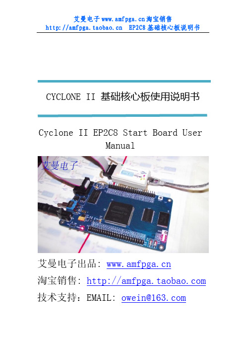
CYCLONE II 基础核心板使用说明书Cyclone II EP2C8 Start Board UserManual艾曼电子出品: 淘宝销售: 技术支持:EMAIL: owein@Version Author Data Desciption V1.0 Hh 2010.5 First draft/bbs版本修订记录1. 模块介绍1.1 模块主要功能数字系统和 SOPC 设计在广大学生和公司和研究所项目开发中已经形成了一定的学习氛围和规模,但市场上的开发板和学习板良莠不齐,为此艾曼电子设计了各种不同层次需求的FPGA电路板模块。
本模块为CYCLONEII EP2C8Q基础核心板,中文名为“Cyclone II EP2C8 基础核心板” ;英文名为“Cyclone II EP2C8Start Board”。
本模块的功能主要包括以 FPGA EP2C8Q208为主芯片及其外围电路构成的核心电路部分, 电源电路部分, LED测试电路部分,IO、控制线和总线引出接口,以及由 SDRAM、SRAM 和 FLASH 构成的存储电路部分。
1.2 模块适用范围本模块适用于高校学生、FPGA项目开发研究者、电子竞赛学生、FPGA电子开发爱好者用于数据采集,高性能数字信号处理(数字滤波、FFT计算、图像处理、模式识别、数据压缩等),主要为学习HDL语言和Nios II软核处理器设计 (偏重于 Nios II)。
同时也作为公司、高校或科研机构为了加快产品和项目开发进程,作为产品的原型板使用。
2. 包装清单2.1 模块包装清单本电路模块主要包括:① EP2C8 基础核心电路板 1块;② 4根安装铜柱和配套螺钉;③ 5V 1A电路板配套的开关电源1个;④ 两张DVD光盘(一张资料光盘,一张软件光盘);可选配件:(具体价格请访问淘宝销售)① Altera ByteBlaster II 并口下载电缆② USB Blaster下载电缆;③ 5V/1A 稳压电源;④ 50 针排线,或杜邦线若干。
cycloneII的中文资料

本科生毕业设计(论文)外文资料译文( 2011 届)译文题目Cyclone II器件系列的简介论文题目Cyclone II Device Family Data Sheet学生姓名学号专业电子信息科学班级指导教师职称信息科学与工程学院教务科制/literature/hb/cyc2/cyc2_cii51001.pdf 外文资料译文规范说明一、外文资料译文:Cyclone II器件系列简介关键词:cyclone II器件;特点;简介;在非常成功的第一代Cyclone器件系列之后,Altera的Cyclone II FPGA系列扩大低成本的FPGA的密度,最多达68,416个逻辑单元(LE),提供622个可用的输入/输出引脚和1.1M比特的嵌入式寄存器。
Cyclone II器件的制造基于300毫米晶圆,采用台积电90nm、低K值电介质工艺,这种工艺技术是使用低绝缘体过程以确保了快速有效性和低成本。
通过使硅片面积最小化,Cyclone II器件可以在单芯片上支持复杂的数字系统,而在成本上则可以和ASIC竞争。
不像其他用电力功耗和性能来换取低成本的FPGA卖主,Altera 最新一代低价位的FPGA——cyclone II FPGA系列,和同类90nmFPGA器件相比,它提高了百分之六十的性能和降低了一半的功耗。
低成本和优化特征使Cyclone II FPGA系列为各种各样的汽车、消费、通讯、视频处理、测试与测量、和其他最终市场提供理想的解决方案。
在参考设计、系统图,和IP,使用cyclone II FPGA系列可以帮助你迅速实现最总市场方案开发。
低成本的嵌入式解决方案Cyclone II 器件支持Nio s II 嵌入式处理器,能够自己完成自定义的嵌入式处理器。
Cyclone II器件还能够扩展各种外部存储器和I/O口或者嵌入式处理器的性能。
单个或多个NiosII嵌入式系统中嵌入式处理器也可以设计成cyclone II设备以提供一些额外的同时处理的能力或者甚至取代已经在你的系统中存在的嵌入式处理器。
Cyclone_II系列FPGA配置

杨宁1041121665Cyclone II系列FPGA配置杨宁 1041121665摘要:由于Cyclone II系列器件是用易失性的SRAM结构单元来存储配置数据的,所以在每次系统上电时都要进行重配置。
用户可以使用DCLK频率高达40MHz的AS(主动串行)模式、PS(被动串行)模式或是JTAG对FPGA器件进行配置操作。
另外,为了减小存储需求和配置时间,Cyclone II系列器件能够使用压缩数据进行配置。
本文的目的是让用户了解Cyclone II器件的配置特点,让用户掌握如何使用Cyclone II器件所支持的配置方式对此系列FPGA进行配置。
同时,也会介绍配置管脚的使用及配置文件的格式等相关信息。
关键词:Cyclone II; FPGA;配置第一节、Cyclone II器件配置概述:用户可以使用AS、PS 和JTAG 模式配置Cyclone II 系列FPGA。
选择何种配置方式取决于MSEL管脚的电平状态,请参照表1-1。
表1-1 Cyclone II 配置模式第二节、配置文件格式表2-1 列出了几个Cyclone II 系列器件的没有压缩过的配置文件的大小(近似值)。
如果要计算多器件配置时的配置数据的存储空间,可以将相应的值相加。
用表2-1 的值只是为了在设计之前大致的估计配置文件的大小。
不同的配置文件格式的大小并不一样,但即使是不同款的设计软件,只要目标器件一定的情况下,那么它编译的无压缩配置文件大小是固定的;而压缩过的文件大小在每次编译时都有所改变,这是由设计时的压缩比例来决定。
第三节、配置数据压缩Cyclone II 器件支持配置数据的压缩,这能节省配置数据存储的空间以及配置时间。
这个特性使得设计者能够将压缩过的配置数据存储在配置芯片或者其他的存储器(Flash)中,并且传送的也是压缩过的数据流文件。
在配置期间,Cyclone II 器件实时解压这些数据流并且将其配置到SRAM 单元中。
Cyclone II FPGA入门开发套件用户指南

引言 ......................................................................................................................................................... 1–1 开始之前的准备工作 ............................................................................................................................. 1–1 详细信息 ................................................................................................................................................. 1–2 硬件安装 ................................................................................................................................................. 1–2 软件安装 .................................................................................................................................................. 1–3
Cyclone II系列FPGA简介
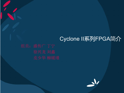
Cyclone II 系列FPGA 的乘法器资源
嵌入式乘法器模块
嵌入式乘法器由两个输入寄存器、一个乘法单元、一个输出寄存器 以及相关的控制信号组成,其内部结构如下图 所示。嵌入式乘法器按列 排列,根据器件不同可以是1 列到3 列。
嵌入式乘法器模块
乘法器的两个操作数可以是符号数,也可以是无符号数。如果两个 操作数都是无符号数,相乘的结果是无符号数,只要其中有一个是符号 数,则相乘的结果是符号数。控制信号signa和signb 分别表示数据A 和 数据B 是符号数还是无符号数,为1 表示为该操作数是符号数,signa和 signb 可以在运行时动态改变。 乘法器有两种工作模式:9×9 模式和18×18 模式。在18×18 模式 下,,乘法器只能配置成1 个18×18 乘法器,两个输入操作数最多可以 是18 位,可以是符号数,也可以是无符号数,输入输出都可以寄存。 在 18 9×9 模式下,一个嵌入式乘法器块可以配置成2 个9×9 乘法器工作。这 种模式下每个乘法器的两个输入操作数最多可以是9 位,可以是符号数, 也可以是无符号数,输入输出都可以寄存。每个乘法器只有一个signa 和 一个signb,当一个乘法器当作两个9×9 乘法器使用时,输入A 的两个输 入符号必须相同,输入数据B 的两个输入也具有相同的符号表示。如果 不是用signa和signb,Quartus II 软件默认乘法器实现无符号乘法。
总结
逻辑单元是Cyclone II系列中可以实现用户逻辑定制的最小单元。 每16个LE组成一个逻辑阵列块(LAB)。LAB以行列形式在FPGA器件中排列, Cyclone II系列FPGA的LE数量从4608到68416范围之间变化 Cyclone II 系列FPGA 有片内PLL,并有最多可达16个全局时钟线 的全局时钟网络为逻辑阵列快、嵌入式存储器块、嵌入式乘法器和输入 输出单元提供时钟。Cyclone II FPGA的全局时钟线也可以作为高速输出 信号使用。Cyclone II的PLL可以实现FPGA 片内的时钟合成、移相,也 可以实现高速差分信号的输出。 M4K 嵌入式存储器块由带校验的4K 位(4096 位)真双口RAM组成, 可配制成真双口模式、简单双口模式或单口模式的存储器,位宽最高可 达36 位,存取速度最高260MHz,M4K嵌入式存储器分布于逻辑阵列块之 间。Cyclone II系列FPGA的M4K 嵌入式存储器的容量从119K位至1152K 位不等。 每个嵌入式乘法器可以配制成两个9×9或一个18×18的乘法器,处 理速度最高达250MHz, Cyclone II 的嵌入式乘法器在FPGA上按列排列。输入输出单元IOE 配列在逻辑阵列块的行和列的末端。可以提供各种类型的单端或差分逻 辑输入输出。
- 1、下载文档前请自行甄别文档内容的完整性,平台不提供额外的编辑、内容补充、找答案等附加服务。
- 2、"仅部分预览"的文档,不可在线预览部分如存在完整性等问题,可反馈申请退款(可完整预览的文档不适用该条件!)。
- 3、如文档侵犯您的权益,请联系客服反馈,我们会尽快为您处理(人工客服工作时间:9:00-18:30)。
用表 4-2 的值只是为了在设计之前大致的估计配置文件的大小。不同的配置文件格式的大小并 不一样,但即使是不同款的设计软件,只要目标器件一定的情况下,那么它编译的无压缩配置文件
4
大小是固定的;而压缩过的文件大小在每次编译时都有所改变,这是由设计时的压缩比例来决定。
第四节、配置数据压缩
Cyclone II 器件支持配置数据的压缩,这能节省配置数据存储的空间以及配置时间。这个特 性使得设计者能够将压缩过的配置数据存储在配置芯片或者其他的存储器(Flash)中,并且传送 的也是压缩过的数据流文件。在配置期间,Cyclone II 器件实时解压这些数据流并且将其配置到 SRAM 单元中。数据压缩能使得配置数据减小 35%---55%左右。 需要注意的是,Cyclone II 器件不支持在 JTAG 模式下的配置数据流的解压缩,只能在 AS 及 PS 模式下进行。 尽管压缩算法一样,但 Cyclone II 器件与增强配置器件(EPC4、EPC8、EPC16)的解压缩特性 却不一样,在增强配置器件中存储的压缩数据在传送给 Cyclone II 器件之前就进行解压缩了。 在 PS 模式下,为了减少配置时间,用户可以使用 Cyclone II 器件的解压特性而发送压缩过的 配置数据进行器件配置。需要注意的是在使用增强配置器件的时候,用户不能同时使用 Cyclone II 和增强配置器件的解压特性。 (在这里要用实例说明,也可能需要演示) 当然也可以在 AS 模式下,使用 Cyclone II 器件的解压特性进行配置,但这个时候用户存放配 置数据的是串行配置器件(EPCS1、EPCS4、EPCS16 or EPCS64) 。 当用户使能了压缩功能,Quartus II 软件就会产生压缩过的配置数据文件。这个压缩文件能够 减少数据在配置器件或 Flash(这种需要协控制器)中存放的空间,当然也能减少配置过程所花费 的时间(可以想出为什么会) 。 有两种方法能够使能 Cyclone II 器件配置数据的压缩:一种是在编译之前(在编译设置中) , 另一种是在编译后(在转换配置文件格式下)(在这里打开 Quartus II 软件演示一下)在此介绍 。 一下后者的基本步骤: 1. 在 File 下拉菜单中点击 Convert Programming Files; 2. 选择编成文件类型。只有 Programmer Object File(.pof)、SRAM HEXOUT(.hexout)、Raw Binary File(.rbf) 、Tabular Text File(.ttf)支持数据压缩; 3. 如果是产生.pof,则需要选择器件; (增强配置器件还可以进行设置) 4. 选择 Add File 增加.sof 文件; 5. 选中加入的.sof 文件,点击 Properties; 6. 选中 Compression 选框。 当用户对多个 Cyclone II 器件进行配置时,配置数据压缩同样也可以针对每个器件进行选择。 在下图 4-2 中,在配置链路上有两个 Cyclone II 器件,如果第一个 Cyclone II FPGA 使用了压缩 使能,那么它会从配置器件中接收到压缩过的配置数据;而第二个 Cyclone II FPGA 没有使用数据 压缩,那么它将接收到非压缩的配置数据流文件。 (在后面章节会详细简述多器件配置问题)
第十节:使用 Flash 配置 Cyclone II 器件: ………………………………………………… 第十一节:配置调试及调试技巧: ………………………………………………………………
1、可靠性配置问题: ………………………………………………………………………… 2、板子 Layout 技巧: ……………………………………………………………………… 3、调试建议: …………………………………………………………………………………
第二节、Cyclone II器件配置概述:
用户可以使用 AS、PS 和 JTAG 模式配置 Cyclone II 系列 FPGA。选择何种配置方式取决于 MSEL 管脚的电平状态,请参照表 4-1。 表 4-1 Cyclone II 配置模式 配置模式 AS(20MHz) PS Fast AS(40MHz) JTAG MSEL1 0 0 1 * MSEL0 0 1 0 * 描述 使用串行配置器件(EPCS1、EPCS4、 EPCS16 或 EPCS64) 使用增强配置器件 (EPC1、 EPC2、 EPC4、 EPC8 或 EPC16)或者是微机加上电缆 同 AS 模式 下载电缆和微机(外部控制器)
5
图 4-2
压缩或不压缩配置数据的配置
第五节、AS 模式:
在 AS 配置模式下,要使用串行配置器件来配置 Cyclone II 系列 FPGA,这些配置器件是低成 本、非易失性设备,只有 4 个信号接口,这些优良特性使其成为理想的低成本配置解决方案。 这种器件使用串行接口来传送串行数据。在配置时,Cyclone II 系列 FPGA 通过串行接口读取 配置数据或经过压缩的数据来配置内部的逻辑单元。这种由 FPGA 来控制外部器件的配置方式就是 主动串行模式(Active serial) ,而有外部设备(如 PC 机,或其他设备)控制 FPGA 进行配置的方 式称为被动串行模式(Passive serial) 。 表 4-3 列出了 AS 配置模式时,MESL 的管脚状态。 表 4-3 Cyclone II 器件配置模式选择 配置模式 AS(20MHz) Fast AS(40MHz) MSEL1 0 1 MSEL0 0 0
第三节、配置文件格式
表 4-2 列出了几个 Cyclone II 系列器件的没有压缩过的配置文件的大小(近似值) 。如果要计 算多器件配置时的配置数据的存储空间,可以将相应的值相加。 表 4-2 Cyclone II 器件的.rbf 文件大小(Raw Binary File) 器件 EP2C5 EP2C8 EP2C20 EP2C35 EP2C50 EP2C70 数据大小(Bits) 1,265,792 1,983,536 3,892,496 6,858,656 9,963,392 14,319,216 数据大小(Bytes) 152,998 247,974 486,526 857,332 1,245,424 1,789,902
第七节、JTAG配置模式: ......................................................... 23
第八节:Cyclone II 器件配置管脚简介: 第九节:总结:
………………………………………………………
……………………………………………………………………………………
2
目录
目录 ............................................................................ 3 第一节、本文介绍: .............................................................. 4 第二节、Cyclone II器件配置概述: ................................................ 4 第三节、配置文件格式 ............................................................ 4 第四节、配置数据压缩 ............................................................ 5 第五节、AS 模式: ............................................................... 6
3
第一节、本文介绍:
由于 Cyclone II 系列器件是用易失性的 SRAM 结构单元来存储配置数据的,所以在每次系统上 电时都要进行重配置。用户可以使用 DCLK 频率高达 40MHz 的 AS(主动串行)模式、PS(被动串行) 模式或是 JTAG 对 FPGA 器件进行配置操作。另外,为了减小存储需求和配置时间,Cyclone II 系列 器件能够使用压缩数据进行配置。 本文的目的是让用户了解 Cyclone II 器件的配置特点,让用户掌握如何使用 Cyclone II 器件 所支持的配置方式对此系列 FPGA 进行配置。同时,也会介绍配置管脚的使用及配置文件的格式等 相关信息。
Cyclone II 系列器件配置手册
--硬件设计培训使用手册
Rev. 0.1
Author Tenglong
Date 2007-1-24
Description First D要面向硬件设计、调试工程师;FPGA 的软、硬件工程师同等
条件培训。但作为 FPGA 硬件设计工程师对本文档中涉及的内容要了如指掌,此为 FPGA 硬件设计工 程师必备手册;当然软件设计人员也要比较熟悉这部分内容。 本文档是培训人员使用手册,其中使用粉红色标记的地方为学员不可见部分,需要培训人员作 详细讲解。本文档培训时间大致为 2 到 3 个小时。
