款丰田卡罗拉自动变速器系统维修手册(英文版)
2016年一汽丰田卡罗拉维修电路图01-如何使用本手册

——转向信号和危险警告灯 (107)——照明、尾灯 (111)——车内照明灯 (119)——前雾灯 (125)——后雾灯 (128)——自动灯光控制、车灯自动熄灭系统 (132)——钥匙提醒(不带智能进入和起动系统) (135)——前刮水器和清洗器 (139)——ABS、TRC、VSC (141)——SRS (150)——换档锁止 (156)——座椅安全带警告 (157)——座椅加热器 (161)——门锁控制 (163)——无线门锁控制(不带智能进入和起动系统) (169)——防盗 (175)——电动车窗 (180)——滑动天窗 (185)——EPS (189)——遥控后视镜(不带卷收器) (193)——遥控后视镜(带卷收器) (195)——喇叭 (197)——点烟器 (198)——电动座椅 (199)——音响系统、后视野监视系统、导航系统 (201)——组合仪表(不带TFT显示屏) (208)——组合仪表(带TFT显示屏) (217)——冷却风扇 (226)——PTC加热器(带手动空调)、手动空调 (231)——PTC加热器(带自动空调)、自动空调 (237)——车灯提醒器 (243)——后窗除雾器、后视镜加热器 (247)——时钟 (250)——接地点 (251)九、插接器表 (259)如何使用本手册 B 本手册将车辆上安装的电路按所属系统划分,提供各系统电路的资料。
各系统电路的实际配线是指从蓄电池开始的电源点到各搭铁点的配线。
(所有电路图均显示所有开关关闭时的状态。
)对任何故障进行故障排除时,首先要了解故障电路的工作原理 (参见“系统电路”一章),了解对此电路供电电源的工作原理 (参见“电源”一章) 和搭铁点的工作原理 (参见“搭铁点”一章),同时还可参见“系统概述”来了解电路的工作原理。
了解电路原理后,可以开始对故障电路进行故障排除,找出故障原因。
利用“继电器位置分布图”和“电路图”来找出各个零件、接线盒和线束连接器、线束和线束连接器及系统电路的搭铁点。
一汽丰田卡罗拉维修维修手册(PO171, 7)
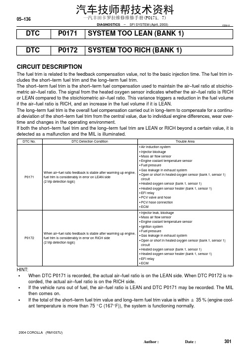
05–136–DIAGNOSTICS SFI SYSTEM (April, 2003)301AuthorĂ:DateĂ:2004 COROLLA (RM1037U)DTCP0171SYSTEM TOO LEAN (BANK 1)DTC P0172SYSTEM TOO RICH (BANK 1)CIRCUIT DESCRIPTIONThe fuel trim is related to the feedback compensation value, not to the basic injection time. The fuel trim in-cludes the short–term fuel trim and the long–term fuel trim.The short–term fuel trim is the short–term fuel compensation used to maintain the air–fuel ratio at stoichio-metric air–fuel ratio. The signal from the heated oxygen sensor indicates whether the air–fuel ratio is RICH or LEAN compared to the stoichiometric air–fuel ratio. This variance triggers a reduction in the fuel volume if the air–fuel ratio is RICH, and an increase in the fuel volume if it is LEAN.The long–term fuel trim is the overall fuel compensation carried out in long–term to compensate for a continu-al deviation of the short–term fuel trim from the central value, due to individual engine differences, wear over-time and changes in the operating environment.If both the short–term fuel trim and the long–term fuel trim are LEAN or RICH beyond a certain value, it is detected as a malfunction and the MIL is illuminated.HINT:SWhen DTC P0171 is recorded, the actual air–fuel ratio is on the LEAN side. When DTC P0172 is re-corded, the actual air–fuel ratio is on the RICH side.SIf the vehicle runs out of fuel, the air–fuel ratio is LEAN and DTC P0171 may be recorded. The MIL then comes on.S If the total of the short–term fuel trim value and long–term fuel trim value is within " 35 % (engine cool-ant temperature is more than 75 _C (167_F)), the system is functioning normally.05DIM–01一汽丰田卡罗拉维修维修手册(PO171, 7)A82386Fuel compensationamount 1.351.00.65+35 (%): Threshold at LEAN –35 (%): Threshold at RICH–DIAGNOSTICS SFI SYSTEM (April, 2003)05–137302AuthorĂ:DateĂ:2004 COROLLA (RM1037U)MONITOR DESCRIPTIONUnder the closed–loop fuel control, fuel injection amounts that deviate from the ECM’s estimated fuel amount will cause a change in the long–term fuel trim compensation value. This long–term fuel trim is ad-justed when there are persistent deviations in the short–term fuel trim values. And the deviation from a simu-lated fuel injection amount by the ECM affects a smoothed fuel trim learning value which is the combination of smoothed short–term fuel trim (fuel feedback compensation value) and smoothed long–term fuel trim (learning value of the air–fuel ratio). When the smoothed fuel trim learning value exceeds the DTC threshold,the ECM interprets this as a fault in the fuel system and sets a DTC.Example:The smoothed fuel trim leaning value is more than +35% or less than –35%, the ECM interprets this as a fail in the fuel system.MONITOR STRATEGY一汽丰田卡罗拉维修维修手册(PO171, 7)05–138–DIAGNOSTICS SFI SYSTEM (April, 2003)303AuthorĂ:DateĂ:2004 COROLLA (RM1037U)TYPICAL ENABLING CONDITIONSTYPICAL MALFUNCTION THRESHOLDSWIRING DIAGRAMRefer to DTC P0130 on page 05–101.INSPECTION PROCEDUREHINT:Hand–held tester only:Narrowing down the trouble area is possible by performing ”A/F CONTROL” ACTIVE TEST (heated oxygen sensor or other trouble areas can be distinguished).(a)Perform ACTIVE TEST using hand–held tester (A/F CONTROL).HINT:”A/F CONTROL” is the ACTIVE TEST which changes the injection volume to –12.5 % or +25 %.(1)Connect the hand–held tester to the DLC3 on the vehicle.(2)Turn the ignition switch ON.(3)Warm up the engine by running the engine speed at 2,500 rpm for approximately 90 seconds.(4)Select the item ”DIAGNOSIS / ENHANCED OBD II / ACTIVE TEST / A/F CONTROL”.(5)Perform ”A/F CONTROL” with the engine in an idle condition (press the right or left button).Result:Heated oxygen sensor reacts in accordance with increase and decrease of injection volume +25 % → rich output: More than 0.5 V,–12.5 % → lean output: Less than 0.4 V一汽丰田卡罗拉维修维修手册(PO171, 7)–DIAGNOSTICS SFI SYSTEM (April, 2003)05–139304AuthorĂ:DateĂ:2004 COROLLA (RM1037U)NOTICE:There is a delay of few seconds in the sensor 1 (front sensor) output, and there is about 20 seconds delay at maximum in the sensor 2 (rear sensor).The following of A/F CONTROL procedure enables the technician to check and graph the voltage outputs of both the heated oxygen sensors.For displaying the graph indication, enter ”ACTIVE TEST / A/F CONTROL / USER DATA”, then select ”O2S B1S1 and O2S B1S2” by pressing ”YES” button and push ”ENTER” button before pressing ”F4” button.HINT:S If different DTCs related to different systems that have terminal E2 as the ground terminal are outputsimultaneously, terminal E2 may be open.S Read freeze frame data using the hand−held tester or the OBD II scan tool. Freeze frame data recordsthe engine conditions when a malfunction is detected. When troubleshooting, it is useful for determin-ing whether the vehicle was running or stopped, the engine was warmed up or not, the air–fuel ratio was lean or rich, etc. at the time of the malfunction.S A high heated oxygen sensor (sensor 1) voltage (0.5 V or more) could be caused by a rich air fuel mix-ture. Check for conditions that would cause the engine to run rich.S A low heated oxygen sensor (sensor 1) voltage (0.4 V or less) could be caused by a lean air fuel mix-ture. Check for conditions that would cause the engine to run lean.一汽丰田卡罗拉维修维修手册(PO171, 7)05–140–DIAGNOSTICS SFI SYSTEM (April, 2003)305AuthorĂ:DateĂ:2004 COROLLA (RM1037U)1CHECK AIR INDUCTION SYSTEM (a)Check the air induction system for vacuum leaks.NG REPAIR OR REPLACE AIR INDUCTION SYSTEMOK2CHECK CONNECTION OF PCV HOSENG REPAIR OR REPLACE PCV HOSEOK3INSPECT FUEL INJECTOR ASSY(INJECTION AND VOLUME) (See page 11–5)NG REPLACE FUEL INJECTOR ASSY (See page 11–10)OK一汽丰田卡罗拉维修维修手册(PO171, 7)A6054832145–200204060801000.10.20.30.51235102030TEMPERA TURE _C(_F)R ESIS T AN CE kΩ(–4)(32)(80)(140)(104)(212)(176)VG E2G+BTHA E2Acceptable05–141306AuthorĂ:DateĂ:2004 COROLLA (RM1037U)OK一汽丰田卡罗拉维修维修手册(PO171, 7)S01196S0169930201053020400.110.30.20.526080100–20(–4)(104)(140)(176)(32)(68)(212)A81700Ohmmeter Acceptable TEMPERATURE _C (_F)R E S I S T A N C E K Ω05–142–DIAGNOSTICS SFI SYSTEM (April, 2003)307AuthorĂ:DateĂ:2004 COROLLA (RM1037U)5INSPECT ENGINE COOLANT TEMPERATURE SENSOR(RESISTANCE)(a)Remove the engine coolant temperature sensor.(b)Measure the resistance between the terminals of the en-gine coolant temperature sensor.Standard:NOTICE:If you checking the engine coolant temperature sensor in water, be careful not to allow water to go into the terminals.After checking, dry the sensor.HINT:Alternate procedure: Connect an ohmmeter to the installed en-gine coolant temperature sensor and read the resistance. Use an infrared thermometer to measure the engine temperature in the immediate vicinity of the sensor. Compare these values to the resistance/temperature graph. Change the engine temper-ature (warm up or allow to cool down) and repeat the test.(c)Reinstall the engine coolant temperature sensor.NG REPLACE ENGINE COOLANT TEMPERATURE SENSOROK6CHECK FOR SPARK AND IGNITION (See page 18–1)NG REPAIR OR REPLACEOK7CHECK FUEL PRESSURE (See page 11–5)(a)Check the fuel pressure (high or low pressure).NG CHECK AND REPLACE FUEL SYSTEMOK8CHECK FOR EXHAUST GAS LEAKAGENG REPAIR OR REPLACE EXHAUST GAS LEAKAGE POINT (See page 15–2)OK一汽丰田卡罗拉维修维修手册(PO171, 7)A85076E3409005–144–DIAGNOSTICS SFI SYSTEM (April, 2003)309AuthorĂ:DateĂ:2004 COROLLA (RM1037U)11INSPECT EFI RELAYOK汽车技师帮技术资料一汽丰田卡罗拉维修维修手册(PO171, 7)A09299A83859Vehicle speed(40 km/h)25mph IG SW OFF40seconds or more 120 seconds or more20 seconds 20 seconds 30 seconds(L 1)(L 3)(L 4)Idling(L 2)(L 3)(L 4)(L 3)40seconds or more 40seconds or more 05–146–DIAGNOSTICSSFI SYSTEM (April, 2003)311AuthorĂ:DateĂ:2004 COROLLA (RM1037U)13REPLACE HEATED OXYGEN SENSORHINT:Check the air induction system for vacuum leaks.GO14PERFORM CONFIRMATION DRIVING PATTERN(a)Connect the hand–held tester to the DLC3. (L 1)(b)Switch the hand–held tester from the normal mode to the check mode (See page 05–11). (L 1)(c)Start the engine and let it idle for 120 seconds or more. (L 2)(d)Drive the vehicle at 25 mph (40 km/h) or more for 40 seconds or more. (L 3)(e)Let the engine idle for 20 seconds or more. (L 4)(f)Perform steps (d) and (e) at least 3 times.HINT:If a malfunction exists, the MIL will be illuminated on the multi–information display during step (f).NOTICE:If the conditions in this test are not strictly followed, detection of a malfunction will not occur. If you do not have the hand–held tester, turn the ignition switch OFF after performing steps from (c) to (f),then perform steps from (c) to (f) again.GO一汽丰田卡罗拉维修维修手册(PO171, 7)05–147312AuthorĂ:DateĂ:2004 COROLLA (RM1037U)一汽丰田卡罗拉维修维修手册(PO171, 7)05–148–DIAGNOSTICSSFI SYSTEM (April, 2003)313AuthorĂ:DateĂ:2004 COROLLA (RM1037U)一汽丰田卡罗拉维修维修手册(PO171, 7)。
2008年TOYOTA自动变速箱配件目录说明书
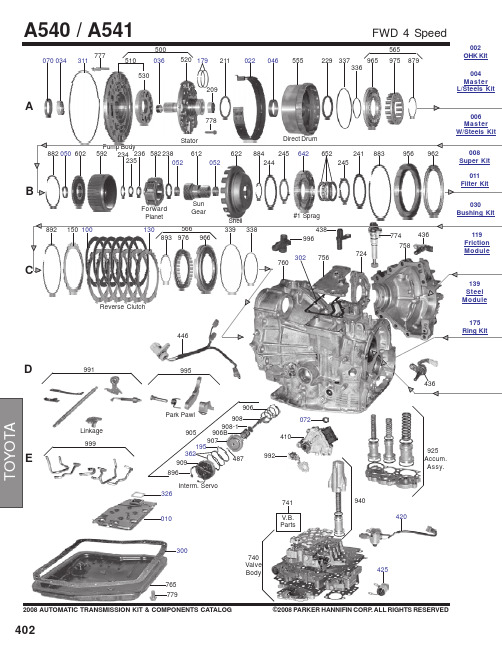
402A070034311530510520179209211022046500555229337336965975879565ForwardPlanetSun GearV.B.Parts741765992446995777778#1 Sprag036779940030Bushing Kit006Master W/Steels Kit 004Master L/Steels Kit002OHK Kit4032008 AUTOMATIC TRANSMISSION KIT & COMPONENTS CATALOG©2008 PARKER HANNIFIN CORP . ALL RIGHTS RESERVEDCD964974122564332333972124100144873888665654888584251246594604889894795207263268710268898590184580216661650694867120100039O.Dr. Cover7967122812806996966818950757350752********PinionFE077725290289720716847292076Differential Diff.Parts717G730715O.Dr. Direct Drum9352692693752917862886982008 AUTOMATIC TRANSMISSION KIT & COMPONENTS CATALOG©2008 PARKER HANNIFIN CORP. ALL RIGHTS RESERVED *Prefix Letter ‘T’ denotes Toledo-Trans Kit (TTK) Brand Transmission Kits*Prefix Letter ‘B’ denotes Bryco Brand Transmission Kits002.............T87002A........Overhaul Kit, A540E 1988-93.....................................................................................................1..........002.............B87002A.......Overhaul Kit, A540E 1988-93.....................................................................................................1..........002.............TF87002A......Overhaul Kit, A540E 1988-93 (Fiber Pan Gasket).....................................................................1..........002.............T87002AB.....Overhaul Kit, A540H (Camry AWD & RAV-4 4x4) 1989-Up......................................................1..........002.............B87002AB.....Overhaul Kit, A540H (Camry AWD & RAV-4 4x4) 1989-Up......................................................1..........002.............T87002B........Overhaul Kit, A541E 1994-Up....................................................................................................1..........002.............TF87002B......Overhaul Kit, A541E 1994-Up (Fiber Pan Gasket).....................................................................1..........002.............B87000B........Overhaul Kit, A541E 1994-Up....................................................................................................1..........004.............B87004A.......Master L/Steels Kit, A540E 1988-5/1991...................................................................................1..........004.............B87004A.......Master L/Steels Kit, A540E 6/1991-1993...................................................................................1..........004.............B87004B........Master L/Steels Kit, A541E 1994-Up..........................................................................................1..........006.............B87006AA.....Master W/Steels Kit, A540E 1988-5/1991..................................................................................1..........006.............B87006AA.....Master W/Steels Kit, A540E 6/1991-1993..................................................................................1..........008.............B87008A.......Super Kit, A540E 1988-91..........................................................................................................1..........E300...........24009T..........Gasket, A540 Oil Pan..................................................................................................................1..........35168-32020 E300...........24018............Gasket, A540 Oil Pan ( Fiber).....................................................................................................1..........(35168-32020) E300...........24009AT........Gasket, A541E Oil Pan 1994-Up.................................................................................................1..........35168-33010 E300...........24018A..........Gasket, A541E Oil Pan 1994-Up (Fiber).....................................................................................1..........(35168-33010) C302...........24097482......Gasket, A540 Top Cover............................................................................................................1..........35153-33010 G304..........24097481......Gasket, A540E/A540H Overdrive Cover (Rear Cover) 1988-Up..............................................1..........34112-32040 A311...........1994536........O-Ring, A540 Pump 1988-Up.....................................................................................................1..........90301-99024 E326...........24006............Gasket, A540 Filter 1988-Up......................................................................................................1..........35339-32020 E362...........1994137........O-Ring, A540 Servo Cover 1988-93..........................................................................................2..........90301-52003 E362...........1994132........O-Ring, A540 Servo Cover 1994-Up.........................................................................................2..........90301-43005 ...................1994584........O-Ring, A540 Filler Tube 1988-Up.............................................................................................1..........90301-09173 ...................1995509........O-Ring, A540 Speed meter Shaft 1988-Up................................................................................1..........96711-24030175.............6142..............Ring Kit, A540 (2 Metal, 8 PTFE).................................................................................................1..........175.............6142OS.........Ring Kit, A540 (2 Metal, 8 PTFE).................................................................................................1..........A177..........30528............Ring, A540 Forward Clutch (PTFE)............................................................................................3..........35712-32010 A179..........TAW-1344.....Ring, A540 Direct Clutch (Metal)................................................................................................2..........35617-16010 E184...........30524............Ring, A540 Intermediate Shaft (PTFE)........................................................................................1..........35748-32010 G185..........30526............Ring, A540 Overdrive Direct Clutch (PTFE)...............................................................................2..........35617-32011 E195...........30537............Ring, A540 2nd Coast Servo (PTFE) 1988-Up...........................................................................1..........35865-32020 E195...........30527............Ring, A541 2nd Coast Servo (PTFE) 1994-Up...........................................................................1..........35865-33010404B100...........24020............Friction, A540 Reverse Clutch (.059") 33 Teeth (5.60"OD)......................................................6-7........35677-32060B100...........24020A..........Friction, A541A Reverse Clutch (.063") 36 Teeth (5.59 OD) 1994-Up.....................................6-7........35677-33040B100...........240022R........Friction, A540 2nd Brake Clutch (.075") 33 Teeth (5.60"OD) 1992-Up.....................................3..........A106..........24026A..........Friction, A540 Forward Clutch (.060") 40 Teeth (5.00"OD) 1992-Up.......................................5..........35633-33010B106...........24028............Friction, A540 Direct Clutch (.083") 40 Teeth (5.20"OD) 1992-Up............................................3..........35633-20010 119.............24080R..........Friction Module A540E 188-91...................................................................................................1.......... 119.............24080............Friction Module A540E 188-91...................................................................................................1.......... 119.............24080AR.......Friction Module A540E 1991-93.................................................................................................1.......... 119.............24080AT........Friction Module A540E 1991-93.................................................................................................1.......... 119.............24080CR........Friction Module, A540H AWD 1989-Up......................................................................................1.......... 119.............24080C..........Friction Module, A540H AWD 1989-Up......................................................................................1.......... 119.............24080BR........Friction Module, A541E 1994-Up................................................................................................1..........A122..........25821C..........Steel, A540 Forward Clutch (.071") 4.10"ID (8 Teeth) 1988-91................................................4..........35634-12040A122..........25821A..........Steel, A540 Forward Clutch (.063") 8 Teeth (4.10"ID) 1992-Up...............................................4..........35634-33010A122..........25821B..........Steel, A540 Forward Clutch (.055") 8 Teeth (4.10"ID) 1992-Up..............................................1-5........35634-33020A122..........24027............Steel, A540 Direct Clutch (.071") 6 Notched Teeth (4.10"ID) 1988-91......................................1..........35634-32020A122..........24027A..........Steel, A540 Direct Clutch (.055") 6 Teeth (4.10"ID) 1992-Up....................................................1..........35634-33030A122..........24027B..........Steel, A540 Direct Clutch (.079") 6 Teeth (3 Teeth Are Notched) 4.10"ID................................2-3........35647-33020F122...........24021............Steel, A540 Overdrive Direct Clutch (.118") 4.10"ID (24 Teeth) 1989-93.................................2..........34615-20010F122...........24021A..........Steel, A541E Overdrive Direct Clutch (.071") 24 Teeth (4.10"ID) 1994-Up...............................2..........34615-33030 ...................25829............Steel, A540 Differential Clutch (.063") 3.60"ID (30 Teeth) 1988-Up..........................................11.........41474-32011B124...........24029............Steel, A540 2nd Brake Clutch (.071") 12 Teeth (4.60"ID) 1988-Up...........................................3..........35648-32030B124...........24025A..........Steel, A541E 2nd Brake Clutch (.071") 10 Teeth (4.86"ID) 1994-Up (Wide Splined)................4..........35648-33010C130...........24029A..........Steel, A541E Reverse Clutch (.063") 10 Teeth (4.86"ID) 1994-Up (Narrow Spline).................6..........35648-33020 139.............24081............Steel Module, A540E 1988-91....................................................................................................1.......... 139.............24081A..........Steel Module, A540E 1991-93....................................................................................................1.......... 139.............24081C..........Steel Module, A540H AWD 1989-Up..........................................................................................1.......... 139.............24081B..........Steel Module, A541E 1994-Up....................................................................................................1..........E010...........25842B..........Filter, A540E/A540H 1988-Up.....................................................................................................1..........E010...........24040B..........Filter, A541E 1994-96.................................................................................................................1..........011.............24041............Filter Kit, A540E/A540H 1988-94................................................................................................1.......... 011.............24041A..........Filter Kit, A540E/A540H 1988-94 (Fiber Pan Gasket)................................................................1.......... 011.............24043............Filter Kit, A541E 1994-Up...........................................................................................................1..........G039..........24033............Bushing, A540 Overdrive Direct Drum (Rear)...........................................................................1..........A046..........24032............Bushing, A540 Direct Drum........................................................................................................1..........B050...........24035............Bushing, A540 Input Hub............................................................................................................1..........B052...........24031............Bushing, A540 Sun Gear...........................................................................................................2..........2008 AUTOMATIC TRANSMISSION KIT & COMPONENTS CATALOG©2008 PARKER HANNIFIN CORP. ALL RIGHTS RESERVED4054062008 AUTOMATIC TRANSMISSION KIT & COMPONENTS CATALOG ©2008 PARKER HANNIFIN CORP. ALL RIGHTS RESERVEDE216...........24073............Washer, A540 Overdrive Planet To Overdrive Drum.................................................................1..........34737-3310...................24074............Washer, A540E Planetary Carrier Sun Gear 1988-93...............................................................1..........35739-32020...................24074A..........Washer, A541E Planet Carrier #3 1994-Up................................................................................1..........35739-33010...................24072............Washer, A540E Planetary Carrier Front 1988-93......................................................................1..........35738-32020...................24072A..........Washer, A541E Planetary# 2 1994-Up ......................................................................................1..........35738-33020...................24071............Washer,A540E Planetary Carrier Rear 1988-93.......................................................................1..........35738-32030...................24071A..........Washer, A541E Planetary# 3 1994-Up ......................................................................................1..........35738-33010E425...........S-151.............Solenoid, A540 Lock-Up 1988-..................................................................................................1..........85420-32110E425...........89758............Solenoid, A540E, A540H Lock Up 1989-Up ...............................................................................1..........85420-32110E425...........S-118.............Solenoid, A541E Lock-Up 1994-04 OEM....................................................................................1..........35240-33010E420...........S-152.............Solenoid, A540E Shift 1, 2 1988-...............................................................................................1..........85420-32091E420...........89757............Solenoid, A540E, A540H Shift 1988-93.....................................................................................1..........85420-32091E420...........S-110.............Solenoid, A541E Shift 1, 2 1994- OEM.......................................................................................1..........85420-33010E420...........89757A..........Solenoid, A541E Shift 1994-Up ..................................................................................................1..........85420-33010B642...........24085............Sprag Assembly, A540 (4 1/2"OD).............................................................................................1..........35790-320312008 AUTOMATIC TRANSMISSION KIT & COMPONENTS CATALOG©2008 PARKER HANNIFIN CORP. ALL RIGHTS RESERVED407。
一汽丰田新卡罗拉轿车K111型无级变速器
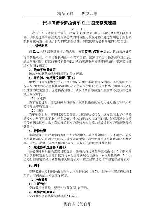
一汽丰田新卡罗拉轿车K111型无级变速器文:王艳一汽丰田新卡罗拉2.0轿车,搭载3ZR-FE型发动机,匹配K111型无级变速器。
该款变速器为带液力变矩器总成的钢带型无级变速器,通过采用电子控制系统和带轮装置,实现了良好的燃油经济性、驾驶的顺畅感和卓越的行驶性能。
一、机械系统在K111型无级变速器中,输入轴上安装着液力变矩器总成、机油泵总成及行星齿轮机构。
行星齿轮机构由一个带轮装置、减速齿轮级及最终齿轮组组成,通过液压控制,持续改变带轮传动比,从而实现变速器的变速功能。
变速器内部结构如图1所示。
2.传动系统原理图该款变速器传动系统原理图如图2所示。
3.前进挡、倒挡开关装置(图3)单个小行星齿轮任凭开关控制机构,以允许车辆前进或倒退。
此机构由锁止行星架的倒挡制动器和将发动机驱动力传递至太阳轮的前进挡离合器组成。
离心机油压力取消室位于前进挡离合器上,以取消离合器放置产生的离心液压并提高液压响应时间。
(1)前进挡当车辆前进时,前进挡离合器接合,发动机输出的驱动力通过输入轴和太阳轮传送至带轮装置中。
(2)倒挡当车辆倒退时,前进挡离合器分离,倒挡制动器接合,这样就阻止了行星架的转动,从而阻止了小齿轮的公转。
输入的驱动力传递至齿圈,然后通过小齿轮再传递到太阳轮。
来自发动机的驱动力旋转方向相反,然后该驱动力输出至带轮装置上。
4.带轮装置带轮装置由钢带和带活塞的一对带轮组成,其结构如图4、图5所示。
为改变带轮传动比,可通过控制液压改变带轮槽宽,这样便可实现带轮传动比无级切换。
此外,提供了较宽的传动比范围,以保证良好的燃油经济性。
5.减速器和差速器(图6)减速器降低带轮装置输出的速度,并将其传递到最终主动齿轮。
2个独立的轴承支撑减速主动齿轮以使其与从动齿轮实现最佳接合,从而降低噪声。
2个小齿轮型前差速器采用斜齿轮作为减速机构,将直齿锥齿轮作为差速器齿轮机构。
6.阀体变速器液压控制阀体由上阀体、下阀体组成(图7),上阀体内部结构如图8所示,下阀内部结构如图9所示。
维修手册英文版
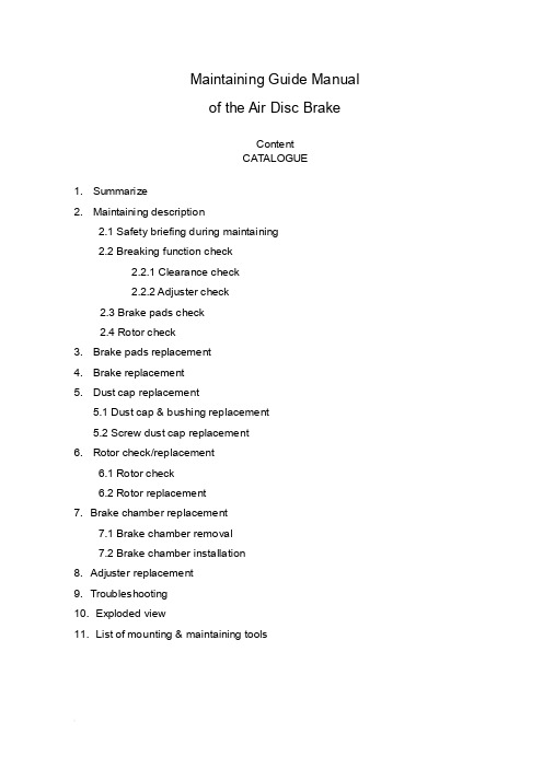
Maintaining Guide Manualof the Air Disc BrakeContentCATALOGUE1. Summarize2. Maintaining description2.1 Safety briefing during maintaining2.2 Breaking function check2.2.1 Clearance check2.2.2 Adjuster check2.3 Brake pads check2.4 Rotor check3. Brake pads replacement4. Brake replacement5. Dust cap replacement5.1 Dust cap & bushing replacement5.2 Screw dust cap replacement6. Rotor check/replacement6.1 Rotor check6.2 Rotor replacement7. Brake chamber replacement7.1 Brake chamber removal7.2 Brake chamber installation8. Adjuster replacement9. Troubleshooting10. Exploded view11. List of mounting & maintaining toolsBrief introduction of YOUFINYOUFIN was established on May 20th, 1998. It is a Sino-Foreign joint-venture enterprise registered in Wuhan Economic and T echnological Development Zone with multi-investors among which private investors dominate. It is a professional company engaged in manufacturing disc brakes and serving the principal automobile manufacturers by providing modularized supply. The main prod ucts cover hydraulic disc brakes and air disk brakes in close to thirty sizes.YOUFIN developed the air disc brake autonomously and patented the product. So far we are the only manufacturer in China that can mass produce air discs to be used in long distance coaches and inner city buses. It is evaluated that the quality of our products is close to the advanced international level in field use. The product development is part of the National T orch Plan and is also sponsored by the Small and Medium-sized Enterprise T echnical Innovation Foundation of Chinese Ministry of S&T.Our Air Disc Brake products are on an absolute leading position in China and the same international level as far as the key technology is concerned.1. SummarizeYOUFIN Air Disc Brake has four sizes (16’’, 17.5’’19.5’’, 22.5’’). It can satisfy different vehicles. The brakes have compact structure; automatically wear compensation and can easily changing the brake pad.2. Maintaining descriptionSafety briefing during maintainingIt’s most important to ensure safety driving and breaking by goodcharacteristics of the brake.Observe brake pad and rotor wear limits. When they warned already to assigned smallest thickness, it need replace immediately, otherwise, it may cause the accident. The pads scorches, grinds or greases must replace immediately.Every pad on each bridge must replace at the same time.When services the brake, the vehicle must park in smooth gound and the wheel withstand with the block/ stone prevent rolls.Note:●Must guarantee it does not occur with careless brake. When replace brakepad don’t make the brake, otherwise, it will hurts the body!●Do not use the compressed air or other cleaning up equipment clean thebrake, in order to avoid injures the body.●Be sure your hands and fingers place outside the caliper, in order to avoidinjures the body.●When moves and installs the brake should have some assistance, avoids ittoo heavy to hurts the body.●When take off the brake to make maintenance, it must fix on the clamp withhigh strength bolt, in order to avoid hurts the body.●Only allowed genuine YOUFIN kits and pads permitted by YOUFIN. Duringthe first 50 miles driving after new pad replacement, should avoid promptlybrake and brake at a long distance, Prevent overhigh temperature.●Allowed genuine YOUFIN kits and brake pads permitted by YOUFIN.●Only can use the recommendation kits in service. Screws the bolt/nutaccording to the request moment of force.Brake Function checkClearance checkProcess:●T ake off the hexagon bolt (39), loosen the pad retainer (38).●Remove pad retainer (38) from caliper.●Remove 3pcs of pad clip (37).●Move the cable (40) to the side.●Push the caliper towards the wheel and check the clearance with tune-upgauge.0.5mm ≤ clearance ≤ 1.2mmNote: Insert tune-up gauge between the caliper (1) and the brake pad (35). Should check the adjuster while the clearance is out of standard.Adjuster checkProcess:●Remove the rubber cap (12).●Turn hexagon head (22) clockwise by wrench to ensure clearance larger than3mm. (Or remove the brake pad and the push board)Note:a. Need enough room (3mm<clearance) for turn adjuster preventing un-fit.b. Never force to adjust the hexagon head (22) and/or the adjuster!Push the pressure arm 5 times in small increments and observe the hexagon head (22). While the adjuster is in good condition, hexagon head (22) must rotate clockwise.c. As the regulated quantity increase, rotation angle decreases.If the adjuster hexagon head (22):a) Not running at allb) Only running at first pushc) Running, but stopped in the middleWhile considers adjuster failed. Y ou should replace the brake on the basis of section 4 or change the adjuster in accordance with section 8.●Keep the clearances at 1mm (section 3) after adjuster check is finished.●Reinstall the rubber cap (12).Brake pads wearing check●Scorches, grinds and greased brake pad must replaces immediately.●Brake pads at the same bridge must replace at the same time.●Brake pad and pad clip must replace at the same time.Rotor checkProcess:●Remove the brake pad according to section 3.●T est thickness of the rotor.Note: Observe the brake pads and the rotor attrition situation. Excessive attrition of the rotor and the brake pads will reduce their potency and causes the brake fail!CAUTION: Rotors on the same bridge must replace at the same time. Single side rotor replacement is unacceptable. Recommend installs new brake pads whilereplace the new rotors.Rotor Dimension limitsRotor jumpiness (↗) check:2.4.1 Process:●Installs division indicator on the bracket (dial guage).●Measure jumpiness (↗) through turns the wheel. Jumpiness (↗) should lessthan 0.15.●Replaces the rotor to satisfy the request of section 6.●Modified brake pad should fulfil the specific requirements in section 3.2.4.2 Rotor test:At each change of Pads check the Rotor for grooves and cracks.The diagram at the right shows possible conditions of the surface.A = Small cracks spread over the surface are allowedB = Cracks less than 0.02in. (0.5mm) wide, running in a Radial direction, are allowedC = Grooves (circumferential) less than 0.06in. (1.5mm) wide are allowedD = Cracks in the vanes are not allowed and the Rotor MUST BE REPLACED.a = Pad contact area3. Brake Pad replacementNote: Do not use the pipe spanner/ board die! Keep your hands and fingers outside the caliper avoid the hurts of body!Brake Pad dismantle process:●T ake off hexagon bolt (39) from the Pad Retainer with spanner.●Remove the pad retainer from caliper (1).●T ake off the pad clip (37), which is above the pads (35,36) and push board (19).●Remove the sensor on brake pad.●T ake off the push board (19) & the brake pads (35,36).●Adjust hexagon head to make tappet back to the initial position.●Clean the pad groove & push board and anchor surface with brush.Note: Don’t hurt the dust cap (5 & 10). Be sure of no grease on installation surface!●Check the adjuster on the basis of section 2.2.2.Note: Fix the key while checking & turning the adjuster cap to avoid screw rotate.●Check the rotor according to section 2.4.3.2 Brake pad installing process:●Need enough room between the caliper & the rotor to insert brake pad.●Insert push board (19) at the place the caliper combine with the adjust screw.Note: Push board must on the bracket supporting surface. Adjust screw pin must in groove. Otherwise it will do harm to Adjuster mechanism. Ensure the dust cap untwisted by rotate the adjust screw.●Insert the cable sensor to pad groove. Fix cable on bearing (40).Note: The sensor contactor must face the brake disc and installs at the correctposition. Attention the wire trend to prevents the friction.●Insert new pad (36) at side of the push board.●Push caliper toward the wheel until the pad touch the rotor.Insert the brake padat wheel side.Note: Don’t adjust hexagon head violently.Note: Turn the adjuster counter-clockwise to decrease the clearance between pads.Don’t install the retainer before adjustment.Note: Check the rubber cap (12), be sure it is correctly seated.4. Brake replacementNote: Don’t use pipe wrench. Ensure your hands and fingers outside the caliperavoid hurt your body!Note: The Brake will supplies in assembly.CAUTION: The left brake and the right brake cannot exchange. Arrow direction on the brake is same as the forward direction of the wheel.4.1 Brake removal process:●Remove brake pad (see Section 3).●Release nut on the caliper, take of brake chamber.●Remove brake assessment from the bridge.●Check brake pad on the basis of section 2.3.●Check rotor on the basis of section 2.4.4.2 Brake installing process:●Install the new brake over rotor on the bridge. Screwed bolt with the spanner.Note: The right install order of the bolt is screwed both side symmetry.●T ake down the flange protection cap on the brake chamber.Note:Air chamber installment position. Open the scupper faces the ground, and stops other mouths.●Install brake pad and push board on the basis of section 3.●Install the air chamber and tighten with spanner.●Adjust the clearance.5. Guide Pin dust cap replacementNote: Do not use the pipe spanner/ board die! Keep your hand & finger outside the caliper, in order to avoid injuries.Note: When replaces all dust cap of guide bushing, section 5.1 & 5.2 should unify to avoids repetitive work. Single bushing replacement according to 5.1 and 5.2 corresponding work orders.5.1. Dust cap & bushing replacement●T ake off the brake pad according to section 3.●Loosen the chamber bolt and remove the brake chamber from caliper.●Remove the caliper assessment from bridge.●T ake off the steel cap (11) from guide bushing (8 & 9) by suitable tools.Dismantle caliper (1) from the bracket (2).Note: Don’t hurt the hole, the lid while open the steel cap with tools.●Loosen the bolt (6 & 7); separate the caliper (1) from the bracket (2).Note: When caliper moves, it may hurt body.●Cleaning up the bracket bonding plane●Take off the guide pin (8&9) on caliper (1). Then remove the dust cap (5).●Presses out bushing 4 with mandril from caliper1.●Cleans up the guide pin hole of caliper.Installing process:●Long guide pin hole must press in two new bushings. Short guide pin holepress in one.●Guarantee the size in drawing.●Greases between them and the bushing●Install new dust cap in the guide pin hole.Note: Cleans up the guide pin hole and grease the edge of dust cap before install for easy installation. Ensure the dust cap installs steadily, without crease and inside the ring groove of the caliper.●Install long/short guide pin to each hole and dust cap upside set in guide pinring groove.●Put the caliper (1) on the bracket (2) and plug guide pin (8&9) in guide hole.●Plug new bolt (6&7) (long one for pin 8, short one for pin 9) and screwed onbracket (2) with spanner.Note: Assembly must be careful, don’t damage the dust cap (5). First, screws bolt on long pin (8), and then screws bolt on short pin (9).When service maintenance, remove the guide pin (8&9) and replace by new bolt (6&7)!●Move the caliper on guide pin (8,9) forward and backward to check whether thecaliper can move freely.●Put on new copper cap on caliper (1) hole and push it in with correct kits. Note: Avoids the hurts of surface.●Raising the guide pin dust cap (5) carefully for cancel the air pressure.●Install brake across the rotor on bridge. Screwed bolt with the spanner.Note: Correct install process of the hexagon bolt.●Install brake pads and adjust clearance. Implemented section 3, notice theexplanation.●Cleaning the install flange on caliper and grease inside the pressure arm ballsocket before reinstall the brake chamber.●Install the brake chamber and screwed with spanner.Note: After the installation of brake chamber, the lowest chamber hole face theground must open, other mouths stop up.5.2. Screw dust cap replacementNote: If only replace the screw dust cap, does not need to remove the caliper andthe air chamber.Process:●Remove brake pad and push board according to section 3.●Push the caliper towards to brake chamber.●T ake off screw dust cap (10) from the ring groove on adjust screw (21).●T ake down from dust cap base with screwdriver.●Check screw thread.●Turning the adjust bolt for 30mm clockwise with the spanner.●Inspection thread corrosion and whether is damaged.●Turning it clockwise, feeling its lubrication and check the adjust screw thread.●Clean the base of caliper dust cap (10). (Arrow pointed)●Push new dust cap (10) on adjust screw. Install it on the base with kits. Observes itinstalls whether arrived.●Grease on the edge of dust cap (10) and install it on the base of adjust screw (21).Note: Guarantees the dust cap steadily in place and does not have the corrugation in the adjust screw ring groove.Installation process:●Install the brake pad and adjust the clearance (see Section 3).6. Rotor check/replacement6.1 Rotor check Check the rotor (Section 2.4) If the rotor reached the minimumthickness, it must be replaced.6.2 Rotor replacementNote: Generally recommend use new brake pad while install new/machined rotor.6.2.1 Uninstall the rotor:●R emove the brake pad. (see section 3)●T ake off the brake chamber. (see section 7)●T ake down brake from bridge. (see section 4)●T ake off the wheel and the rotor.(Refer to V ehicle Manufacture’srecommendations)6.2.2 Rotor installation:●I nstall the wheel and rotor. (refer to V ehicle Manufacture’s recommendations)●D egrease the rotor.●T urn the wheel and check the installed rotor (Section 2.4).●A djust ABS sensor refer to V ehicle Manufacture’s recommendations.●I nstall the brake (see Section 4).●I nsert pad (see Section 3).●I nstall brake chamber (see Section 7).7. Brake chamber replacementNote: Don’t use pipe wrench! Ensure your hands and fingers outside the caliperavoid hurts body!Note: Can only use the chamber assigned by the Vehicle Manufacture.7.1. Brake chamber removal:●Bleeds off the compressed air.●Remove the upper air pipe of brake chamber.●Remove the chamber from caliper.7.2. Brake chamber installation:Note: According to the brake installment position, only can open the scupperunderneath.●Cleans the sealing plane of the pressure are ball socket (arrow) and caliper beforethe brake chamber installation.●Screwed the chamber mounting nut alternately with spanner in torque ratingrequired by the air chamber supplier.●Connection the air pipe.Note: Never twist the braking line, place it originally avoid fiction with other sets.While exist air leak, finds the leakage and check the connection.●Function and performance examination.8. A djuster replacement8.1 A djuster removal●Remove brake pad (see Section 3).●Remove brake chamber (see Section 7).●T ake off brake (see Section 4).●T ake off upper bolt by hexagon wrench.●Remove adjuster and other parts in the caliper.Note: Don’t hurt the screw dust cap.8.2 A djuster installation●Grease inside the caliper.●Put the return spring (18) at each side.●Install the needle assembly and the adjuster.●Puts the washer and top head, screwed the bolt with spanner according to theopposite angle principle.Note: Guarantee the bolt tighted the moment of force.9. Troubleshooting11. List of mounting & maintaining toolsYOUFIN is in the process of logo replacement, new logo will put into practice gradually. It with the original logo is still the YOUFIN’s product. Final interpret right for the logo belongs to YOUFIN.。
丰田卡罗拉维修手册
SAE Technical Standards Board Rules provide that: “This report is published by SAE to advance the state of technical and engineering sciences. The use of this report is entirely voluntary, and its applicability and suitability for any particular use, including any patent infringement arising therefrom, is the sole responsibility of the user.”SAE reviews each technical report at least every five years at which time it may be reaffirmed, revised, or cancelled. SAE invites your written comments and suggestions.QUESTIONS REGARDING THIS DOCUMENT: (724) 772-8512 FAX: (724) 776-0243TO PLACE A DOCUMENT ORDER; (724) 776-4970 FAX: (724) 776-0790SAE WEB ADDRESS 1.Scope—This SAE Recommended Practice defines the information contained in the header and data fields ofnon-diagnostic messages for automotive serial communications based on SAE J1850 Class B networks. This document describes and specifies the header fields, data fields, field sizes, scaling, representations, and data positions used within messages.The general structure of a SAE J1850 message frame without in-frame response is shown in Figure 1. The structure of a SAE J1850 message with in-frame response is shown in Figure 2. Figures 1 and 2 also show the scope of frame fields defined by this document for non-diagnostic messages. Refer to SAE J1979 for specifications of emissions related diagnostic message header and data fields. Refer to SAE J2190 for the definition of other diagnostic data fields. The description of the network interface hardware, basic protocol definition, the electrical specifications, and the CRC byte are given in SAE J1850.FIGURE 1—SCOPE OF SAE J2178 FOR A SAE J1850 FRAME WITHOUT IN-FRAME RESPONSE (IFR)FIGURE 2—SCOPE OF SAE J2178 FOR A SAE J1850 FRAME WITH IN-FRAME RESPONSE (IFR)SAE J1850 defines two and only two formats of message headers. They are the Single Byte header format and the Consolidated header format. The Consolidated header format has two forms, a Single Byte form anda three byte form. This document covers all of these formats and forms to identify the contents of messageswhich could be sent on a SAE J1850 network.This document consists of four parts, each published separately.SAE J2178-1 (Titled: Detailed Header Formats and Physical Address Assignments) describes the two allowed forms of message header formats, Single Byte and Consolidated. It also contains the physical node address range assignments for the typical sub-systems of an automobile.SAE J2178-2 (Titled: Data Parameter Definitions) defines the standard parametric data which may be exchanged on SAE J1850 (Class B) networks. The parameter scaling, ranges, and transfer functions are specified. Messages which refer to these parametric definitions shall always adhere to these parametric definitions. It is intended that at least one of the definitions for each parameter in this part matches the SAE J1979 definition.SAE J2178-3 (Titled: Frame IDs for Single Byte Forms of Headers) defines the message assignments for the single byte header format and the one byte form of the consolidated header format.SAE J2178-4 (Titled: Message Definition for Three Byte Headers) defines the message assignments for the three byte form of the consolidated header format.2.References2.1Applicable Publications—The following publications form a part of this specification to the extent specifiedherein. Unless otherwise specified, the latest issue of SAE publications shall apply.2.1.1SAE P UBLICATIONS—Available from SAE, 400 Commonwealth Drive, Warrendale, PA 15096-0001.SAE J1213-1—Glossary of Vehicle Networks for Multiplex and Data CommunicationSAE J1850—Class B Data Communication Networks InterfaceSAE J1930—Electrical/Electronic Systems Diagnostic Terms, Definitions, Abbreviations, and AcronymsSAE J1979—E/E Diagnostic Test ModesSAE J2190—Enhanced E/E Diagnostic Test Modes2.1.2ANSI/IEEE P UBLICATION—Available from ANSI, 11 West 42nd Street, New York, NY 10036-8002.ANSI/IEEE 754-1985—IEEE Standard for Binary Floating-Point Arithmetic3.Definitions3.1Data [Data Field]—Data and data field are used interchangeably in this document and they both refer to afield within a frame that may include bytes with parameters pertaining to the message and/or secondary ID and/or extended addresses and/or test modes which further defines a particular message content being exchanged over the network.3.2Extended Address—The extended address is a means to allow a message to be addressed to ageographical location (such as geographic) or zone of the vehicle, independent of any node's physical address.3.3Frame—A frame is one complete transmission of information which may or may not include an In-FrameResponse. The frame is enclosed by the start of frame and end of frame symbols. For Class B networks, each frame contains one and only one message (see "message" definition below).3.4Frame ID—The Frame ID is the header byte for the Single Byte Header format and the one byte form of theconsolidated header format. The definition of the frame ID is found in SAE J2178-3. This header byte defines the target and source and content of the frame.3.5Functional Addressing—Functional addressing allows a message to be addressed or sent to one or morenodes on the network interested in that function. Functional addressing is intended for messages that may be of interest to more than a single node. For example, an exterior lamp "off" message could be sent to all nodes controlling the vehicle exterior lamps by using a functional address. The functional address consists of a primary ID and may include a secondary ID and may also include an extended address.3.6Header [Header Field]—The header (or header field, used interchangeably) is a one or three byte field withina frame which contains information about the message priority, message source and target addressing,message type, and in-frame response type.3.7In-Frame Response (IFR) Type—The IFR type identifies the form of the in-frame response which is expectedwithin that message.3.8Load—The load command indicates the operation of directly replacing the current/existing value of aparameter with the parameter value(s) contained in the message.3.9Message—A message consists of all of the bytes of a frame excluding the delimiter symbols (SOF, EOD,EOF, NB).3.10Modify—The modify command indicates the operation of using the message data parameter value to change(e.g., increment, decrement, or toggle) the current/existing value.3.11Parameter—A parameter is the variable quantity included in some messages. The parameter value, scaling,offset, units, transfer function, etc., are unique to each particular message. (The assigned parameters are contained herein.)3.12Physical Addressing—Physical addressing allows a message to be addressed to a specific node or to allnodes or to a non-existent, null node. The information in this message is of relevance only to a particular node, so the other nodes on the bus should ignore the message, except for the case of the "all nodes" address.3.13Primary ID—The primary ID identifies the target for this functional message. This is the primary discriminatorused to group functions into main categories.3.14Priority—The priority describes the rank order and precedence of a message. Based upon the SAE J1850,Class B arbitration process, the message with the highest priority will win arbitration.3.15Report—A report indicates the transmission of parametric data values, based on: a change of state; a changeof value; on a periodic rate basis; or as a response to a specific request.3.16Request—A request is a command to, or a query for data, or action from another node on the network.3.17Response Data—The response data is the information from a node on the network in response to a requestfrom another node on the network. This may be an in-frame response or a report type of message.3.18Secondary ID—The secondary ID (along with the primary ID or Frame ID) identifies the functional target nodefor a message. The purpose of the secondary ID field within the frame is to further define the function or action being identified by the primary ID.4.Abbreviations and AcronymsA/C - Air ConditioningASC - ASCII Encoded SLOTBCD - Binary Coded Decimal (BCD) SLOTBMM - Bit Mapped with Mask SLOTBMP - Bit Mapped without Mask SLOTCRC - Cyclic Redundancy CheckCS - ChecksumDTC - Diagnostic Trouble CodeEOD - End of DataEOF - End of FrameERR - Error DetectionEV-ETS - Electric Vehicle Energy Transfer SystemEVSE - Electric Vehicle Supply EquipmentHVAC - Heating, Ventilation, Air ConditioningID - IdentifierIFR - In-Frame ResponseLSB - Least Significant Bit/ByteMSB - Most Significant Bit/ByteNB - Normalization BitPID - Parameter IDentification (number, NOT the primary ID, (See Section 7)PKT - Multiple Parameter Packet SLOTPRN - Parameter Reference NumberSED - State Encoded SLOTSFP - Signed Floating Point (Scientific Notation) SLOTSLOT - Scaling, Limit, Offset, and Transfer Function (See Section 8)SNM - 2's Complement Signed Numeric SLOTSOF - Start of FrameUNM - Unsigned Numeric SLOTVIN - Vehicle Identification Number5.General Information5.1Part 1 Overview—The messages defined by this four part document are specified for networks using singlebyte headers or consolidated one and three byte headers as specified in SAE J1850. Sections 6 and 7 of SAE J2178-1 provide the system architecture for the different possible headers used in Class B network communication (see Appendix A for supporting discussion). Section 8 of SAE J2178-1 defines the data fields used by the different header byte formats. Section 9 of SAE J2178-1 defines the physical address assignments.Figure 3 shows an overview of this part (Part 1) which encompasses the different possible messages and their component parts.FIGURE 3—PART 1 OVERVIEWSAE J1850 defines two and only two formats of message headers. They are the Single Byte header format and the Consolidated header format. The Consolidated header format has two forms, identified by the value of the H Bit. The two forms are: a one byte form and a three byte form. The information in the header field for both formats contains target, source, priority and message type information, while the data field contains additional addressing and/or parametric information and/or diagnostic test modes. This information is explicitly defined in some headers and implicitly defined in others. Messages defined by this document (Parts 1, 2, 3, and 4) are classified generally into two types:a.Requests, that is, commands (load or modify) or queries for data, andb.Responses, that is, reports or acknowledgments.When a node generates a request, the target nodes which are responsible for the requested data or function must respond by reporting the requested information or by performing the requested function. For responses (that is, reports or acknowledgments), data information that a node responds with may have been previously requested by another node, or reported by the node when the desired information has changed, or reported by the node on a periodic basis.SAE J2178-1 describes the overall structure of messages. In total, parts 1, 2, 3, and 4:a.Fully define SAE (automotive industry) standard messages.b.Reserve messages for future SAE standardization.c.Reserve messages for manufacturers to allocate, which are typically unique or proprietary to thatmanufacturer.In order to comply with this document, implementations need to use the defined messages on SAE J1850 networks in the exact way that they are defined here. However, there are a large number of message codes that are reserved for each manufacturer to independently allocate.5.2In-Frame Response Field Formats—The total number of bytes in the frame (not including frame delimiters) is12, including the header (1 or 3 depending on header type), data (both in the message and IFR), and single byte CRC. Therefore, the total number of message and IFR data bytes can be 10 if using a single byte header or the one byte form of the consolidated header, or 8 bytes if using the three byte form of the consolidated header.5.2.1I N-F RAME R ESPONSE T YPE 0—The in-frame response type 0 is used to indicate the form without any in-frameresponse.5.2.2I N-F RAME R ESPONSE T YPE 1—The in-frame response type 1 is a single byte response from a singleresponder. The response byte shall be the physical address of a receiver of the message. No CRC byte is included for this response data.5.2.3I N-F RAME R ESPONSE T YPE 2—The in-frame response type 2 is a single byte response from multipleresponders. The response byte(s) shall be the physical address of the receiver(s) of the message. No CRC byte is included for the response data.5.2.4I N-F RAME R ESPONSE T YPE 3—The in-frame response type 3 is a multiple byte response from a singleresponder. The response bytes shall be data (generally not its address) from a single responder. The second CRC byte is included for the data integrity of the response data. The actual in-frame response data shall be one byte in length, as a minimum.Figure 4 illustrates the four IFR types.FIGURE 4—TYPES OF IN-FRAME RESPONSE6.Single Byte Header Messages and Format—For single byte header messages, the entire byte is used todefine the message identifier (ID) as shown in Figure 5. This allows up to 256 unique message identifiers to bedefined. Standard message identifiers that utilize this header format are found in SAE J2178-3.All single byte header messages utilize one of the four in-frame response (IFR) types Figure 4.7.Consolidated Header Messages and Format—The consolidated header format includes both a one byte form and a three byte form.7.1One Byte Form of the Consolidated Header Format—The one byte form utilizes 7 bits for the message identifier thereby allowing up to 128 distinct Ids. The H bit (bit 4) is always a logic "1" signifying the one byte form of the consolidated header. Figure 6 illustrates this message header form. Standard message identifiers that utilize this header form are defined in SAE J2178-3.FIGURE 6—ONE BYTE FORM OF CONSOLIDATED HEADERIn order to accommodate a one byte header form and a three byte header form on the same network, the header type bit (H bit) in the first byte of the message has been defined to indicate the header form. This bit is defined in Table 1.All one byte header form messages of the consolidated header format utilize one of the four in-frame response (IFR) types (see Figure 4).7.2Three Byte Form of the Consolidated Header Format—This header form utilizes the first three bytes of the message. The H bit (bit 4) is always a logic "0" signifying the three byte form. Standard message identifiers that utilize this header form are defined in SAE J2178-4. The remaining seven bits of the first byte contain information about priority (PPP) and message type (KYZZ). The second byte contains the target address information. The target can be either functionally addressed or physically addressed. The third byte contains the physical address of the source of the message. Arbitration is always resolved by the end of the third byte,since the source address must be unique. Figures 7 and 8 illustrate this message header form.FIGURE 7—THREE BYTE FORM OF CONSOLIDATED HEADERTABLE 1—H BIT DEFINITIONH Bit Header Byte Form 0Three Byte Form 1One Byte FormFIGURE 8—FIRST BYTE OF THREE BYTE FORM OF CONSOLIDATED HEADERAll three byte header messages utilize one of the four in-frame response (IFR) types (see Figure 4, 4).7.2.1P RIORITY /T YPE -B YTE 1—The priority/type byte contains information about priority, in-frame response,addressing type, and type modifier. Each of the field definitions is described in the following paragraphs.7.2.1.1Priority (PPP Bits)—The priority field is three bits in length and immediately proceeds the header type (H)bit. The priority bit definition is shown in Table 2. The priority bit assignments for a particular message are manufacturer specific and are not assigned by SAE J2178.7.2.1.2Header Type (H Bit)—In order to accommodate a one byte header form and a three byte header form on the same network, the header type bit (H bit) in the first byte of the message has been defined to indicate the header form. This bit is defined in Table 3.TABLE 2—PRIORITY FIELD ASSIGNMENTSPPP Bits Priority Level 0000Highest0011.0102.0113.1004.1015.1106.1117LowestTABLE 3—H BIT DEFINITIONH Bit Head Byte Form 0Three Byte Form 1One Byte Form7.2.1.3In-Frame Response (K Bit)—The necessity for in-frame response is encoded into a single bit in the priority/type byte. This bit definition is shown in Table 4.TABLE 4—"K" BIT ASSIGNMENTSK Bit In-Frame Response0Required1Not Allowed7.2.1.4Addressing Type (Y Bit)—Message addressing is encoded with a single bit in the priority/type byte. Thisbit definition is shown in Table 5.TABLE 5—"Y" BIT ASSIGNMENTSY Bit Addressing Type0Functional1Physical7.2.1.5Type Modifier (ZZ Bits)—The type modifier is encoded as a two bit field (ZZ) and is used in conjunctionwith the in-frame response bit (K) and the address type bit (Y) to define sixteen message types,see Table 6.TABLE 6—THE SIXTEEN MESSAGE TYPESMsg Response Addressing IFRType KYZZ(K bit)(Y bit)Type Message Type (Name)00000Required Functional2Function10001Required Functional1Broadcast20010Required Functional2Function Query30011Required Functional3Function Read40100Required Physical1Node-to-Node50101Required Physical—Reserved - MFG60110Required Physical—Reserved - SAE70111Required Physical—Reserved - MFG81000Not Allowed Functional0Function Command/Status91001Not Allowed Functional0Function Request/Query101010Not Allowed Functional0Function Ext. Command/Status111011Not Allowed Functional0Function Ext. Request/Query121100Not Allowed Physical0Node-to-Node131101Not Allowed Physical0Reserved - MFG141110Not Allowed Physical0Acknowledgement151111Not Allowed Physical0Reserved - MFGNOTE 1—Functional addresses for the three byte form of the consolidated header are defined in SAE J2178-4.Physical address ranges are defined in Section 7 of this part.NOTE 2—Message types 8 and 9 use functional data format #2 only; message types 10 and 11 use functional dataformat #3 only.NOTE 3—Reserved - SAE indicates reserved for future SAE Committee action. Reserved - MFG indicates thatmanufacturers are allowed to allocate these definitions without requiring any commonality between motorvehicle manufacturers.7.2.2TARGET A DDRESS -B YTE 2—The second byte of the three byte form of the consolidated header format contains either a functional or physical target address. The physical address assignments are found in Section 8 of this part, while functional message address assignments are in SAE J2178-4.Functional addresses are assigned in pairs where the only difference between the ID values is the least significant bit (W bit). Figure 9 illustrates the functional target address with W bit.FIGURE 9—FUNCTIONAL TARGET ADDRESSThe W bit is logic "0" to signify a Command target and logic "1" to signify a Status target. This bit is defined in Table 7.7.2.3S OURCE A DDRESS -B YTE 3—The third byte of the three byte format of the consolidated header format is the physical address of the source of the message. Physical address assignments are found in Section 9.These physical address assignments shall be unique for each node of a network.8.Data Field Formats—In both message header formats, single byte and consolidated, the data field can usually be encoded in the same way. This section briefly describes the different ways that information can be formatted in the data field. The data field immediately follows the header field. The number of bytes in this field will vary, based upon the content of the header field. The maximum data field length is limited by the requirements of SAE J1850. Because of differences in functionally and physically addressed messages or with in-frame response data, these cases are defined separately.8.1Functional Data Field Formats8.1.1F UNCTIONAL D ATA F IELD F ORMAT 0—One of the functional data field formats is, in fact, no additional bytes of data (an empty data field). The message consists of the header, error checking byte, and in-frame response bytes. This is the format used for functional message types 2 and 3. Because the data field does not actually exist but to allow referencing in other parts of this document, it has been identified as the functional data field format 0.8.1.2F UNCTIONAL D ATA F IELD F ORMAT 1—In the simplest case including data (format 1), the data field contains only parametric data. The first byte of the data field in this case contains the most significant byte of data.The data field must contain one byte as a minimum. Figure 10 illustrates this message format. This data field format may be used for message types 0 and 1 only.FIGURE 10—FUNCTIONAL DATA FIELD FORMAT 1TABLE 7—W BIT DEFINITIONW Bit Functional Target Address Type0Command 1Status8.1.3F UNCTIONAL D ATA F IELD F ORMAT 2—In a data field format 2 message, the data field contains a byte which isused to further define the target function being addressed. In this format type, the data field would appear as shown in Figure 11. This data format may be used for message types 0, 1, 8 and 9.FIGURE 11—FUNCTIONAL DATA FIELD FORMAT 2The secondary address byte consists of a parameter/quantity bit (Q bit) in which binary data (such as, on/off or yes/no) can be encoded. There is a listing of the possible uses for this bit in SAE J2178-4. The control bit(C bit) is used to distinguish between an immediate load of data or a modify of the current data for commandmessages, or to distinguish between request/report and query message operations. The remaining six bits specify a secondary ID address. The order of these bits within the secondary address byte is shown in Figure 12.FIGURE 12—SECONDARY ADDRESS BYTE FORMATIn many cases, a single data bit (i.e., the Q bit) is not adequate to define the data parameter being sent. In this case, the identifier field is followed by an additional data field as illustrated in Figure 13. The combination of the primary and secondary addresses defines whether additional data is used by that message.FIGURE 13—FUNCTIONAL DATA FIELD FORMAT 2, WITH DATA BYTES8.1.3.1The Parameter/Quantity Bit (Q bit)—The Q bit is used to represent single, binary values. Refer to SAEJ2178-4 for a list of valid uses for the Q bit.8.1.3.2The Control Bit (C bit)—The C bit represents an action or operation to be taken with the associated datavalues. Table 8 shows how the W and C bits are used in conjunction with the eight functionally addressed messages types (0-3, and 8-11) to define a particular message operation.Modify messages adjust (e.g., increment/decrement) or toggle the state of existing data. Load messages replace current or existing data. Request messages "ask" for existing status or command data. Report messages "tell" existing status. Query messages "ask" for the receivers of a message without asking for the associated data.8.1.3.3The Secondary ID—The secondary identification field is used to further identify the particular function or operation being addressed by this message. It is used to distinguish a function when the primary ID is not sufficient, or to define a specific operation to be performed by the function addressed by the primary ID.These secondary identification addresses are assigned in SAE J2178-3 and SAE J2178-4.8.1.4F UNCTIONAL D ATA F IELD F ORMAT 3—In a data field format 3 message, depending on the particular primary and secondary ID, the data field may also contain an extended address byte which defines the geographical location within the vehicle of the target function being addressed. This data field format may be used for message types 0 and 1 and must be used for message types 10 and 11. In this data field type, the data field appears as shown in Figure 14.TABLE 8—MESSAGE OPERATIONSMsg Type KYZZ W C Message TypeMessage Operation000000FunctionLoad Command 01Modify Command 10Report Status 11MFG Specific 1000100Broadcast Load Command 01Modify Command 10Report Status 11MFG Specific 200100n/a Function Query Command Query 1n/a Status Query 30011n/a n/a Function Read Not Applicable 8100000Function Command/StatusLoad Command 01Modify Command 10Report Status 11MFG Specific 9100100Function Request/Query Status Request 01Report Acknowledge 10Command Request 11Function Query10101000Function Ext. Command/StatusLoad Command Extended 01Modify Command Extended 10Report Status Extended 11MFG Specific11101100Function Ext. Request/QueryStatus Request Extended 01Report Acknowledge Extended 10Command Request Extended 11Function Query ExtendedFIGURE 14—FUNCTIONAL DATA FIELD FORMAT 3The extended address byte is used to determine where, geographically on a vehicle, a particular function is located. The exact definition of the extended address values can be found in 8.3. The secondary address in Figure 14 is used as defined in 8.1.3.As in the other data field formats, a parameter data field may also be needed and in this case it is then appended to the end of the other identifiers. This format is shown in Figure 15.FIGURE 15—FUNCTIONAL DATA FIELD FORMAT 3, WITH DATA BYTES8.1.5F UNCTIONAL D ATA F IELD F ORMAT 4—In this data field format message, the data field contains a byte whichdefines the diagnostic test mode of the target function being addressed. In this type, the data field would appear as shown in Figure 16. This data format may be used for message types 0, 1, 8 and 9.FIGURE 16—FUNCTIONAL DATA FIELD FORMAT 4The test mode byte is used to determine which diagnostic function is involved. It may be followed by parameter data fields. In this case, the additional data bytes follow the test mode byte. This format is shown in Figure 17. This is the format for functionally addressed diagnostic messages such as those found in SAE J1979.FIGURE 17—FUNCTIONAL DATA FIELD FORMAT 4, WITH DATA BYTES8.2Physical Data Field Formats—The previous section (8.1) defined the data field formats for functionallyaddressed messages. This section (8.2) defines the data field formats for physically addressed messages. 8.2.1P HYSICAL D ATA F IELD F ORMAT 0—One of the physical data field formats is, in fact, no additional bytes of data(an empty data field). The message consists of the header, error checking byte, and may be with or without in-frame response bytes. This is the format used for the acknowledgement message type. This message type simply confirms to another node that the message has been received correctly. Because this data field does not actually exist but to allow referencing in other parts of this document, it has been identified as the physical data field format 0.8.2.2P HYSICAL D ATA F IELD F ORMAT 1—Physical data field format 1 is generally associated with the node-to-nodemessage types. This message type is the one utilized for enhanced E/E diagnostic test modes (see SAE J2190). This format assumes the three byte form of the consolidated header format. The single byte format and the one byte form of the consolidated header format are covered in physical data field format 2 (see8.2.3). Many of the specific diagnostic messages are defined in SAE J2190. This description of the format isconsistent with SAE J2190 but expands the definition to allow the format to be used in other messages as well. In particular, the manufacturer specific applications of this node-to-node message are expected to follow this format. The basic format is similar to the functional data field format 4. The format is shown in Figure 18.FIGURE 18—PHYSICAL DATA FIELD FORMAT 1The format will often include data bytes as shown in Figure 19. The contents of the test mode byte indicate if additional data bytes are used.FIGURE 19—PHYSICAL DATA FIELD FORMAT 1, WITH DATA BYTES The physical test mode byte details are shown SAE J2190.8.2.3P HYSICAL D ATA F IELD F ORMAT 2—In order to maximize commonality between the different header byteformats, the physical data field format 2 is essentially the same as physical data field format 1 with the insertion of the physical target address byte ahead of the physical test mode byte. This allows the single byte header format and the one byte form of the consolidated header format to operate consistently with the three byte header form. The format is shown in Figures 20 and 21 for the two cases, without and with additional data bytes, respectively.FIGURE 20—PHYSICAL DATA FIELD FORMAT 2FIGURE 21—PHYSICAL DATA FIELD FORMAT 2, WITH DATA BYTES8.3Extended Addressing—Extended addressing defines an extended (geographical) location in the vehicle.The upper two bits of the extended address (RR) are used to allow up to four different types of extended addressing. Table 9 shows these bit assignments.TABLE 9—EXTENDED ADDRESS TYPESRR Type00Geographical Addressing01Reserved - SAE10Reserved - MFG11Reserved - MFG。
2004款丰田卡罗拉仪表系统维修手册(英文版)
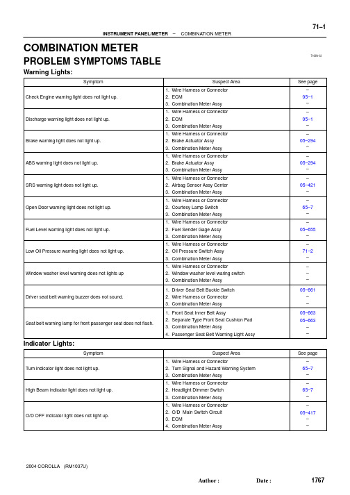
7108N–03–INSTRUMENT PANEL/METERCOMBINATION METER71–11767AuthorĂ:DateĂ:2004 COROLLA (RM1037U)COMBINATION METERPROBLEM SYMPTOMS TABLEWarning Lights:Indicator Lights:7108O–01I32114C9–10C9–171–2–INSTRUMENT PANEL/METERCOMBINATION METER1768AuthorĂ:DateĂ:2004 COROLLA (RM1037U)ON–VEHICLE INSPECTION1.INSPECT SPEEDOMETER (a)Check the operation.(1)Using a speedometer tester, inspect the speedometer fro allowable indication error and checkthe operation of the odometer.Reference:NOTICE:Tire wear and tire over or under inflation will increase the indication error.(2)Check the deflection width of the speed meter indicator.Reference: Below 0.5 km/h / 0.3 mph2.INSPECT OUTPUT SIGNAL OF VEHICLE SPEED (a)Check for standard signal.(1)While driving the vehicle at the speed of 10 km/h,check the voltage between the terminals C9–10and C9–1 of the combination meter assy.Standard: Fluctuation between 10 to 14 V or less is re-peated 7 times within 1 sec.NOTICE:Check it with the ignition switch ON and the connector con-nected.(a)Inspect the circuit.(1)Disconnect the connecto(2)T urn the ignition switch Oof the receiver gauge neNeedle position: EMPTY(3)Connect terminals 2 andconnector and T urn thecheck the position of theNeedle position: FULLGm the sender gauge.heck the fuel level needle indicates EMPE RECEIVER GAUGE W ARNING LIGHm the sender gauge.heck the position of the water temperatu on the wire harness side connector, thenauge needle.71–4–INSTRUMENT PANEL/METERCOMBINATION METER1770AuthorĂ:DateĂ:2004 COROLLA (RM1037U)7.INSPECT LOW OIL PRESSURE WARNING LIGHT (a)Inspect the circuit.(1)Disconnect the connector from the low oil pressure switch.(2)Turn the ignition switch ON.(3)Connect the terminal of wire harness side connector and ground, then check the warning lowoil pressure warning light.Low oil pressure warning light: Light on 8.INSPECT LOW OIL PRESSURE SWITCH (a)Check the continuity.(1)Disconnect the connector from the low oil pressure switch.(2)Check that continuity exists between terminal and ground.Engine stopped: continuity Engine running: no continuity9.INSPECT BRAKE WARNING LIGHT (a)Inspect the parking brake warning light.(1)Disconnect the connector from the parking brake switch and ground terminal on the wire harnessside connector.(2)Turn the ignition switch ON and check that the warning light lights up.(b)Inspect the brake fluid level warning light.(1)Disconnect the connector from the brake fluid level warning switch and connect terminals on thewire harness side connector.(2)Turn the ignition switch ON and check that the warning light lights up.10.INSPECT BRAKE FLUID LEVEL WARNING SWITCH (a)Inspect the continuity.(1)Remove the reservoir tank cap and strainer.(2)Disconnect the connector.(3)Check that the continuity exists between the terminals.Float up (switch off): No continuity(4)Use syphon, etc., to take fluid out of the reservoir tank.(5)Check that the continuity exists between the terminals.Float down (switch on): Continuity(6)Pour the fluid back in the reservoir tank.I32305Light Switch Key Unlock Warning Switch Courtesy Switch (Driver’s side)BuzzerON OFF OFFOFFON ONON 0.2SH40113C9–18C9–17C9–16C9–1C9–2C9–4C9–5I32306Key Unlock Warning SwitchIG Switch Courtesy Switch (Driver’s side)BuzzerONOFF ON OFF(LOCK,ACC)OFFONONONONONON0.5S "0.2SH40113C9–17C9–16C9–1C9–2C9–4C9–5–INSTRUMENT PANEL/METERCOMBINATION METER71–51771AuthorĂ:DateĂ:2004 COROLLA (RM1037U)11.INSPECT LIGHT AUTO TURN OFF BUZZER (a)Check the operation.HINT:When the key unlock warning and light auto turn off warning is output simultaneously, the key unlock warning precedes the other.(1)Remove the ignition key with the tail light switch ONand the driver side door open and check for the buzzer.Buzzer sound: Continuous(2)While the buzzer is sounding, perform any of the fol-lowing and check that the buzzer sound is stopped.S Turn the tail light switch OFF.S Close the driver side door.S Insert the ignition key into the key cylinder.(b)Check the function.(1)Remove the combination meter.(2)Connect the position (+) lead from battery to termi-nal C9–5 and negative (–) lead to terminal C9–1and C9–2.(3)Connect the position (+) lead from battery to termi-nal C9–18 and negative (–) lead to terminal C9–16and C9–17, check that the buzzer sound.Buzzer sound: Continuous(4)While the buzzer is sounding, connect the batterypositive terminal to terminal C9–4 and check that the buzzer sound is stopped.12.INSPECT KEY UNLOCK WARNING BUZZER (a)Check the operation.HINT:When the key unlock warning and light auto turn off warning is output simultaneously, the key unlock warning precedes the other.(1)While the driver side door is open, insert the ignitionkey, set the ignition switch to OFF (LOCK or ACC)and check for the buzzer sound.Buzzer sound: Intermittent (b)Check the function.(1)Remove the combination meter.(2)Connect the position (+) lead from battery to termi-nal C9–5 and negative (–) lead to terminal C9–1and C9–2.(3)Connect the negative (–) lead to terminal C9–16and C9–17, check that the buzzer sound.Buzzer sound: Intermittent71–6–INSTRUMENT PANEL/METERCOMBINATION METER1772AuthorĂ:DateĂ:2004 COROLLA (RM1037U)(4)While the buzzer is sounding, connect the battery positive terminal to terminal C9–4 and check that the buzzer sound is stopped.7108M–01B59495Front Pillar Garnish LHInstrument Panel Sub–assy UpperFront Pillar Garnish RHInstrumentPanel Register Assy No.1JHeater Control & Accessory AssyDJInstrument Panel Register Assy No.3Instrument ClusterFinish Panel Sub–assy CenterKGrove Compartment Door Sub–assyIKKKInstrument ClusterFinish Panel JControlKnob Sub–assy Glove Compartment Door AssyM/T Transaxle:Floor Shift Shift Lever Knob Sub–assy Console Panel UpperMeter Hood Sub–assyCombination Meter AssySteeringColumn CoverWindshield Wiper Switch AssyHeadlampDimmer SwitchSteering Wheel AssyHorn Button Assy8.8 (90, 78 in.⋅lbf)N ⋅m (kgf ⋅cm, ft ⋅lbf): Specified torque20 (204, 15)L50 (510, 37)Combination Meter Glass–INSTRUMENT PANEL/METERINSTRUMENT PANEL/METER71–71773AuthorĂ:DateĂ:2004 COROLLA (RM1037U)INSTRUMENT PANEL/METERCOMPONENTSB59496EG or HG or HECInstrument Panel Box SpringInstrument Panel BoxCowl Side Trim Board RHFront Door Scuff Plate RHConsole Box CarpetA/T Transaxle:Console Box Sub–assy RearFront Door Scuff Plate LHCowl Side Trim Board LHParking Brake Hole Cover Sub–assyFFJJ JJG or HA or B71–8–INSTRUMENT PANEL/METERINSTRUMENT PANEL/METER1774AuthorĂ:DateĂ:2004 COROLLA (RM1037U)7108I–01–INSTRUMENT PANEL/METERINSTRUMENT PANEL SUB–ASSY LOWER71–91775AuthorĂ:DateĂ:2004 COROLLA (RM1037U)INSTRUMENT PANEL SUB–ASSY LOWERPRECAUTION1.PRECAUTION FOR VEHICLE WITH SRS AIRBAG AND SEAT BELT PRETENSIONER(a)Some operations in this section may affect the SRS airbag. Before performing the corresponding op-erations, please read the NOTICE of the SRS airbag to perform the proper operations.7108J–02B59370CodeShapeφ=6(0.24)L=30(1.18)CodeShapeCodeShapeφ=7(0.28)L=30(1.18)φ=6(0.24)L=20(0.79)mm (in.)(L = Length)φ=8(0.32)L=18(0.71)φ=6(0.24)L=16(0.63)φ=6(0.24)L=25(0.98)φ=6(0.24)L=20(0.79)φ=7(0.28)L=20(0.79)φ=5(0.20)L=14(0.55)φ=5(0.20)L=14(0.55)φ=5(0.20)L=16(0.63)φ=5(0.20)L=18(0.71)71–10–INSTRUMENT PANEL/METERINSTRUMENT PANEL SUB–ASSY LOWER1776AuthorĂ:DateĂ:2004 COROLLA (RM1037U)REPLACEMENTHINT:COMPONENTS: See page 71–71.TABLE OF BOLT, SCREW AND NUT NOTICE:Be sure to tape the tip of the screwdriver when using it to disengage the meshing of the clips and claws.HINT:Indicate the bolts, screws and nuts, which are necessary for installation and removal of the instrument panel,in the illustration and the text with alphabets.2.PRECAUTION3.SEPARATE BATTERY NEGATIVE TERMINAL(See page 60–1)4.PLACE FRONT WHEELS FACING STRAIGHT AHEAD5.REMOVE HORN BUTTON ASSY(See page 60–13)6.REMOVE STEERING WHEEL ASSY(See page 50–8)SST 09950–50013 (09951–05010, 09952–05010, 09953–05020, 09954–05021)B593417 ClawsB59342B59344: 4 Claws1777AuthorĂ:DateĂ:2004 COROLLA (RM1037U)7.REMOVE METER HOOD SUB–ASSY (a)Remove the clip.(b)Using a screwdriver, disengage the 7 claws, then remove the meter hood sub–assy.HINT:Tape the screwdriver tip before use.8.REMOVE COMBINATION METER ASSY (a)Remove the screw<L>.(b)Disengage the 2 claws as shown in the illustration.(c)Disconnect the connector, then remove the combination meter assy.9.REMOVE INSTRUMENT PANEL REGISTER ASSY NO.1(a)Using a moulding remover, disengage the 4 claws, then remove the instrument panel register assy No.1.10.REMOVE INSTRUMENT PANEL REGISTER ASSY NO.311.REMOVE FLOOR SHIFT SHIFT LEVER KNOB SUB–ASSY (M/T TRANSAXLE)B593436 ClawsB597714 Claws4 Clips I322922 Clips4 Claws B59350: Stoppers1778AuthorĂ:DateĂ:2004 COROLLA (RM1037U)12.REMOVE CONSOLE PANEL UPPER(a)Using a screwdriver, disengage the 6 claws.HINT:Tape the screwdriver tip before use.(b)Disconnect the connector, then remove the console panelupper.13.REMOVE HEATER CONTROL KNOB14.REMOVE INSTRUMENT CLUSTER FINISH PANEL (a)Remove the screw<J>.(b)Using a screwdriver, disengage the 4 clips and 4 claws,then remove the instrument cluster finish panel.HINT:Tape the screwdriver tip before use.(c)Disconnect the connectors.NOTICE:Do not pull the lid of auxiliary box.15.REMOVE INSTRUMENT CLUSTER FINISH PANEL SUB–ASSY CENTER(a)Remove the 4 screws<K>.(b)Using a screwdriver, disengage the 2 clips and 4 claws,then remove the instrument cluster finish panel sub–assy center with radio receiver assy.HINT:Tape the screwdriver tip before use.(c)Disconnect the connectors.16.REMOVE GLOVE COMPARTMENT DOOR ASSY(a)Remove the screw<I> from the glove compartment door stopper sub–assy.(b)Deform the upper part of the glove compartment door assy to release the stoppers.(c)Pull the glove compartment door assy upward to remove it.B59351: Clip : 2 ClawsB593523 Clips 8 Claws1779AuthorĂ:DateĂ:2004 COROLLA (RM1037U)17.REMOVE FRONT PILLAR GARNISH LH (a)Disengage the clip.(b)Pull the front pillar garnish LH upward and disengage the 2 claws, then remove the front pillar garnish LH.18.REMOVE FRONT PILLAR GARNISH RH19.SEPARATE PASSENGER AIRBAG CONNECTOR(See page 60–25)20.REMOVE INSTRUMENT PANEL SUB–ASSY UPPER (a)Remove the bolt<D> and 2 screws<J>.(b)Using a moulding remover, disengage the 3 clips and 8 claws.(c)Remove the instrument panel sub–assy upper.21.REMOVE HEATER CONTROL & ACCESSORY ASSY(See page 55–13)22.REMOVE STEERING COLUMN COVER(See page 50–8)23.REMOVE HEADLAMP DIMMER SWITCH ASSY(See page 65–23)24.REMOVE WINDSHIELD WIPER SWITCH ASSY(See page 66–11)B59353B593544 ClawsB59355A/T Only:B593567 Claws1780AuthorĂ:DateĂ:2004 COROLLA (RM1037U)25.REMOVE GLOVE COMPARTMENT DOOR STOPPER SUB–ASSY(a)Disengage the clip, then remove the glove compartment door stopper sub–assy.26.REMOVE PARKING BRAKE HOLE COVER SUB–ASSY(a)Using a screwdriver, disengage the 4 claws, then remove the parking brake hole cover sub–assy.HINT:Tape the screwdriver tip before use.27.REMOVE CONSOLE BOX CARPET28.REMOVE CONSOLE BOX SUB–ASSY REAR (M/T TRANSAXLE)29.REMOVE CONSOLE BOX SUB–ASSY REAR (a)A/T Transaxle:Remove the 2 bolts<F>, 4 screws<J> and console box sub–assy rear.(b)M/T Transaxle:Remove the 2 bolts<F>, 2 screws<J> and console box sub–assy rear.30.REMOVE FRONT DOOR SCUFF PLATE LH(a)Using a screwdriver, disengage the 7 claws, then remove the front door scuff plate LH.HINT:Tape the screwdriver tip before use.31.REMOVE FRONT DOOR SCUFF PLATE RHB59357: ClipB59358<G> or <H><G> or <H><G> or <H><E><E><C><A> or <B>1781AuthorĂ:DateĂ:2004 COROLLA (RM1037U)32.REMOVE COWL SIDE TRIM BOARD LH (a)Remove the clip.(b)Disengage the clip, then remove the cowl side trim board LH.33.REMOVE COWL SIDE TRIM BOARD RH34.REMOVE INSTRUMENT PANEL SUB–ASSY LOWER (a)Disconnect the DLC3 connector.(b)Remove the hood lock control lever.(c)Remove the 3 screws<G> or <H>.(d)Remove the 2 bolts<E>.(e)Remove the bolt<A> or <B>.(f)Remove the bolt<C>.(g)Remove the 8 clips and instrument panel sub–assy lower.35.REMOVE INSTRUMENT PANEL BOX36.REMOVE INSTRUMENT PANEL BOX SPRING37.INSTALL HEATER CONTROL & ACCESSORY ASSY(See page 55–13)1782AuthorĂ:DateĂ:2004 COROLLA (RM1037U)38.INSTALL INSTRUMENT PANEL SUB–ASSY UPPER (a)Install the instrument panel sub–assy upper.(b)Install the bolt<D> and 2 screws<J>.Torque:Bolt <D>: 20 N ⋅m (204 kgf ⋅cm, 15 ft ⋅lbf)39.INSTALL INSTRUMENT CLUSTER FINISH PANEL SUB–ASSY CENTER 40.CENTER SPIRAL CABLE(See page 60–22)41.INSTALL STEERING WHEEL ASSY(See page 50–8)42.INSPECT STEERING WHEEL CENTER POINT 43.INSPECT HORN BUTTON ASSY(See page 60–13)44.INSTALL HORN BUTTON ASSY(See page 60–13)45.INSPECT SRS WARNING LIGHT7108K–01B59342E50427–INSTRUMENT PANEL/METERCOMBINATION METER ASSY1783AuthorĂ:DateĂ:2004 COROLLA (RM1037U)COMBINATION METER ASSYOVERHAULHINT:COMPONENTS: See page 71–71.REMOVE METER HOOD SUB–ASSY(See page 71–10)2.REMOVE COMBINATION METER ASSY (a)Remove the screw.(b)Disengage the 2 clips as shown in the illustration.(c)Disconnect the connector, then remove the combination meter.3.REMOVE COMBINATION METER GLASS(a)Disengage the 8 claws, then remove the combination me-ter glass.7108L–01B597894 Claws–INSTRUMENT PANEL/METERCLOCK ASSY1784AuthorĂ:DateĂ:2004 COROLLA (RM1037U)CLOCK ASSYREPLACEMENT1.REMOVE CONSOLE PANEL UPPER(See page 71–10)2.REMOVE HEATER CONTROL KNOB3.REMOVE INSTRUMENT CLUSTER FINISH PANEL(See page 71–10)4.REMOVE CLOCK ASSY(a)Using a screwdriver, disengage the 4 claws, remove the clock as shown in the illustration.HINT:Tape the screwdriver tip before use.。
一汽丰田卡罗拉维修维修手册(headligh)

1 P3 Parking Brake SW
R
1 G–O R–B (*4) 1 D2 Daytime Running Light Relay
11 PKB
4 FOG
TAIL 14
DIM 13
BRK 10
DRL 1
H–LP 6 4 IA2 R–Y 1
W–R
R–W
R–W
G–B
R–Y
(* 1)
(* 3)
(* 2)
L–W R–W L–W R–W R–B
From Power Source System (See Page 48) * * * * 1 : USA 2 : w/ ABS 3 : w/o ABS 4 : w/ Fog Light 1 40A HEAD MAIN 2 Combination SW R–B 1 R 1 3 HEAD Relay 2 1 R–Y R–B 5 1 R–B
2 1 IA4 1 R–B R–B
2
1 R–B
2 W–B
R–B
I3 W–B W–R G–B(* 1)
W–B
H4 Headlight RH (Low)
H2 Headlight LH (Low)
B R–W
R–W
R
W–B
71
2004 COROLLA (EWD533U)
Headlight
汽车技师帮技术资料
T D2 Daytime Running Light Relay 7
H
HI 16 2
(*1)
E
8 3B G–W (*1)
6 3C W–B 5 3C 4 3C R R–Y R 3 13 12 8 9 IA4 Dimmer SW Low High Flash W–B C12 Combination SW 10 W–B (* 1) 11 W–B W–B A
2004款丰田卡罗拉无线遥控门锁系统技术诊断维修手册(英文版)

05DUB–01–DIAGNOSTICSWIRELESS DOOR LOCK CONTROL SYSTEM05–685850AuthorĂ:DateĂ:2004 COROLLA (RM1037U)WIRELESS DOOR LOCK CONTROL SYSTEMHOW TO PROCEED WITH TROUBLESHOOTINGHINT:STroubleshooting of the wireless door lock control system is based on the premise that the power door lock system is operating normally. Therefore, before troubleshooting the wireless door lock control sys-tem, first make certain that the the power door lock system is operating normally.SUse this procedure to troubleshoot the wireless door lock control system.1VEHICLE BROUGHT TO WORKSHOP2CUSTOMER PROBLEM ANALYSIS CHECK AND SYMPTOM CHECK (See page 05–686)3PROBLEM SYMPTOMS TABLE (See page 05–691)(a)If the fault is not listed on the problem symptoms table, proceed to A.(b)If the fault is listed on the problem symptoms table, proceed to B.BGo to step 5A4OVERALL ANALYSIS AND TROUBLESHOOTING(a)Terminals of ECU (See page 05–688)(b)On–vehicle inspection (See page 73–8)5ADJUST , REPAIR OR REPLACE6CONFIRMATION TESTEND056B8–07WIRELESS DOOR LOCK CONTROL SYSTEM Check SheetCustomer’s NameVINProduction Date Licence No.Odometer ReadingInspector’s Namekm miles//////Date Vehicle Brought inDate Problem First Occurred Frequency Problem OccursWeather Conditions When Problem OccurredDate Transmitter Battery Last ReplacedWeatherOutdoorTemperature PlaceConstant Sometimes ( times/per day, month)Once onlyFine Cloudy Rainy SnowyVarious/OthersHotWarm CoolCold (Approx. °C ( °F))EverywhereSpecific Locality ( )//P r o b l e m S y m p t o m sWhole wireless door lock control system does not operate.Only door unlock function does not operate.Only door lock function does not operate.Doors are locked by wireless door lock operation even when doors are open.Wireless door lock functions abnormally.Others05–686–DIAGNOSTICSWIRELESS DOOR LOCK CONTROL SYSTEM851AuthorĂ:DateĂ:2004 COROLLA (RM1037U)CUSTOMER PROBLEM ANALYSIS CHECK056BB–04B59374Front Door Lock LHRear Door Lock LHFront Door Courtesy Switch LHRear Door Lock RHRear Door Courtesy Switch LHDoor Control Receiver (Located inside the Roof Side Garnish Inner RH)TransmitterFront Door Lock RHUnlock Warning SwitchPower Window Master Switch (Door Lock Control Switch LH)Instrument Panel J/B (Integration Relay)Rear Door Courtesy Switch RHFront Door Courtesy Switch RHDoor Lock Control Switch RH–DIAGNOSTICSWIRELESS DOOR LOCK CONTROL SYSTEM05–687852AuthorĂ:DateĂ:2004 COROLLA (RM1037U)LOCATION056BC–02B57790I11Integration Relay Connector (Wire Harness Side)05–688–DIAGNOSTICSWIRELESS DOOR LOCK CONTROL SYSTEM853AuthorĂ:DateĂ:2004 COROLLA (RM1037U)TERMINALS OF ECU1.INSPECT INTEGRATION RELAY(a)Disconnect the connector from the integration relay.(b)Check the continuity between each terminal of the disconnected connector and the body ground, as shown in the illustration and table.Standard:If the result is not as specified, the vehicle’s side may malfunction.(c)Reconnect the connector and check the voltage between each terminal and the body ground, asshown in the illustration and table.Standard:If the result is not as specified, the integration relay may malfunction.B5937605–690–DIAGNOSTICSWIRELESS DOOR LOCK CONTROL SYSTEM855AuthorĂ:DateĂ:2004 COROLLA (RM1037U)(a)Disconnect the connectors IA, IB, ID, IF, IH and IJ of the instrument panel J/B.(b)Check the continuity between each terminal of the disconnected connectors and the body ground, as shown in the illustration and table.Standard:If the result is not as specified, the vehicle’s side may malfunction.(c)Reconnect the connectors and check the voltage between each terminal and the body ground, asshown in the illustration and table.Standard:If the result is not as specified, the integration relay or instrument panel J/B assembly may malfunction.056BD–07–DIAGNOSTICSWIRELESS DOOR LOCK CONTROL SYSTEM05–691856AuthorĂ:DateĂ:2004 COROLLA (RM1037U)PROBLEM SYMPTOMS TABLEB7040051+BGNDRDA PRG23L–R G–Y Instrument Panel J/BIntegration RelayIDID RDAPRG 78W–BBH108L–YJ9D3Door Control ReceiverW–BJ8A AJ/C48U1Unlock Warning Switch Assy Center J/B J6J/C KSWIJL–B164A 4A15L–B12W–B AIEToBattery05–692–DIAGNOSTICSWIRELESS DOOR LOCK CONTROL SYSTEM857AuthorĂ:DateĂ:2004 COROLLA (RM1037U)ONLY WIRELESS CONTROL FUNCTION DOES NOT OPERATE (PREPARE NEW OR NORMAL TRANSMITTER OF THE SAME TYPE VEHICLE)CIRCUIT DESCRIPTIONThe door control receiver receives a signal from the transmitter and sends this signal to the integration relay.Then, the integration relay controls door operation by sending a door LOCK/UNLOCK signal to each door lock motor.WIRING DIAGRAM05DUC–01–DIAGNOSTICSWIRELESS DOOR LOCK CONTROL SYSTEM05–693858AuthorĂ:DateĂ:2004 COROLLA (RM1037U)INSPECTION PROCEDUREHINT:The switch described in this text is a switch for transmitting signals which is built in the door control transmit-ter.1CHECK WIRELESS DOOR LOCK CONTROL FUNCTIONS (See page 73–8)NGGo to step 2OK NORMAL2REPLACE TRANSMITTER BATTERY WITH NORMAL ONE(a)After replacing the transmitter battery with a new or normal one, check that the doors can lock and unlock by using the transmitter LOCK/UNLOCK switch.NGGo to step 3OKREPLACE TRANSMITTER BATTERY3CHECK WIRELESS DOOR LOCK CONTROL FUNCTIONS(a)Check if UNLOCK–LOCK operates in standard operation.NOTICE:Standardized test procedure: Press the transmitter switch for 1 second, directing the beam to driver side door outside handle from a distance of 1 m (39.4 in.). The transmitter should be pointed directly at the door handle, i.e at 90_ angle to the vehicle body.NGREPLACE DOOR CONTROL TRANSMITTEROK4CONFIRM ROOM LAMP ON(a)Check that the wireless door lock buzzer sounds.B52341Room Lamp OFFa: 0.25 sec.b: 0.5 sec.ON ab05–694–DIAGNOSTICSWIRELESS DOOR LOCK CONTROL SYSTEM859AuthorĂ:DateĂ:2004 COROLLA (RM1037U)5SWITCH TO SELF–DIAGNOSTIC MODE(a)Switch to self–diagnostic mode by operating the ignition key cylinder.(1)Put the vehicle under the vehicle’s initial condition (See page 73–8), insert the key into the igni-tion key cylinder and remove it.(2)Within 5 seconds after the key is removed (step 1), insert the key into the ignition key cylinder(ignition key OFF) and perform the following once: Turn the ignition switch to ON and return it to OFF.(3)Within 30 seconds after the ignition switch is returned to OFF (step 2), perform the following 9times: Turn the ignition switch to ON and return it to OFF.NOTICE:If operation has failed, the system will return to normal mode.HINT:S Turning the ignition switch ON after step 3 has been completed will end self–diagnostic mode.S Do not lock or unlock doors during self–diagnostic mode.(b)Check that the system has switched to self–diagnostic mode by the blinking frequency of the room lamp.NG Go to step 9OKNormal wave of UNLOCK switch is receivedNo diagnosis outputsRoom Light OutputONOFFT1: 0.25 sec.T2: 0.5 sec.Wave ReceivingRoom Light OutputONOFFRoom Light OutputOFFT1T1T1T2Normal wave of LOCK switch is receivedRoom Light OutputONOFFT1T2Unmatching recognition code6CHECK BY SELF–DIAGNOSTIC MODE(a)Inspect the diagnosis outputs when the door control transmitter switch is held down (The diagnosis outputs can be checked with the outputs of the room lamp).HINT:S In the case of a reception of the normal wave of the door LOCK and UNLOCK switch (room lamp blink-ing), go to step A.S In the case of an unmatching recognition code (room lamp ON), go to step B.SIn the case of no diagnosis outputs (room lamp OFF), go to step C.A Go to step 16CGo to step 8B7REGISTER RECOGNITION CODE(a)Check that the system can switch to rewrite mode or add mode and whether a recognition code can be registered.NGGo to step 15OK NORMAL8CHECK RESPONSE OF DOOR CONTROL RECEIVER(a)When a new or normal door control transmitter switch for the same type vehicle is held down, checkthat a diagnosis of unmatching recognition code is output.NG Go to step 12OKREPLACE DOOR CONTROL TRANSMITTER9CONFIRM INPUT METHOD OF SELF–DIAGNOSTIC MODE(a)When the method for switching the system to self–diagnostic mode works, proceed to A.(b)When the method for switching the system to self–diagnostic mode does not work, proceed to B.B Go to step 5A10INSPECT UNLOCK WARNING SWITCH ASSYPushedB51903U1IJ21Instrument Panel J/B (Wire Harness Side)Door Control Receiver (Wire Harness Side)CHECK WIRE HARNESS (DOOR CONTROL RECEIVERB51174Door Control ReceiverD3B59377Instrument Panel J/B(Wire Harness Side)Door Control Receiver (Wire Harness Side)IDD313CHECK DOOR CONTROL RECEIVER(a)Reconnect the connector to the door control receiver, and check the voltage between the terminal and the body ground, as shown in the illustration and table.Standard:NGGo to step 15OK14CHECK WIRE HARNESS (DOOR CONTROL RECEIVER ⇔ INSTRUMENT PANEL J/B) (DOOR CONTROL RECEIVER OR INSTRUMENT PANEL J/B ⇔ BODY GROUND)OK15REPLACE DOOR CONTROL RECEIVER WITH NORMAL ONENG Go to step 16OKREPLACE DOOR CONTROL RECEIVER16REPLACE INTEGRATION RELAY WITH NORMAL ONENG REPLACE INSTRUMENT PANEL JUNCTIONBLOCK ASSYOKREPLACE INTEGRATION RELAY。
丰田卡罗拉2007(COROLLA2007)整车电路图手册

6
COROLLA_EWD-B.fm Page 7 Saturday, May 12, 2007 2:50 PM
B
[O] : 解释系统概述。
[P] : 显示系统电路中的零件在车辆上的位置的参考页码。
例 : 零件 “H4”( 灯故障传感器 ) 在手册的 36 页。
* 该代码的第一个字符表示指示线束的字母,第二个字符表示与线束连接的零件的系列号。
电源 ( 电流流程图 ) . . . . . . . . . . . . . . . . . . . . . . . . J . . . . 336
连接器表 . . . . . . . . . . . . . . . . . . . . . . . . . . . . . . . . K . . . . 344
2
COROLLA_EWD-B.fm Page 3 Saturday, May 12, 2007 6:37 PM
如何使用本手册 B 本手册将车辆上安装的电路按所属系统划分,提供各系统电路的资料。 各系统电路的实际配线是指从蓄电池开始的电源点到各搭铁点的配线。 ( 所有电路图 均显示所有开关关闭时的状态。 ) 对任何故障进行故障排除时,首先要了解故障电路的工作原理 ( 参见 “系统电路”一 章 ),了解对此电路供电电源的工作原理 ( 参见“电源”一章 ) 和搭铁点的工作原理 ( 参 见 “搭铁点”一章 ),同时还可参见 “系统概述”来了解电路的工作原理。 了解电路原理后,可以开始对故障电路进行故障排除,找出故障原因。利用 “继电器 位置分布图”和 “电路图”来找出各个零件、接线盒和线束连接器、线束和线束连接 器及系统电路的搭铁点。为使您更清楚地了解接线盒内的连接情况,本手册还提供了 每个接线盒内部的电路图。 在各系统电路中用箭头 ( 从 ___,到 ___ ) 标示与各系统相关的配线。如果需要了解总 体连接情况,请参见本手册末的 “总电路图”。
Toyota Corolla Highway Assist System说明书
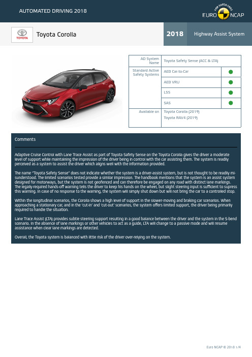
CommentsAdaptive Cruise Control with Lane Trace Assist as part of Toyota Safety Sense on the Toyota Corolla gives the driver a moderate level of support while maintaining the impression of the driver being in control with the car assisting them. The system is readily perceived as a system to assist the driver which aligns well with the information provided.The name “Toyota Safety Sense” does not indicate whether the system is a driver-assist system, but is not thought to be readily mi-sunderstood. The limited scenarios tested provide a similar impression. The handbook mentions that the system is an assist system designed for motorways, but the system is not geofenced and can therefore be engaged on any road with distinct lane markings. The legally-required hands-off warning tells the driver to keep his hands on the wheel, but slight steering input is sufficient to supress this warning. In case of no response to the warning, the system will simply shut down but will not bring the car to a controlled stop.Within the longitudinal scenarios, the Corolla shows a high level of support in the slower-moving and braking car scenarios. When approaching a stationary car, and in the ‘cut-in’ and ‘cut-out’ scenarios, the system offers limited support, the driver being primarily required to handle the situation.Lane Trace Assist (L TA) provides subtle steering support resulting in a good balance between the driver and the system in the S-bend scenario. In the absence of lane markings or other vehicles to act as a guide, L TA will change to a passive mode and will resume assistance when clear lane markings are detected.Overall, the Toyota system is balanced with little risk of the driver over-relying on the system.AD SystemName Toyota Safety Sense (ACC & L TA)Standard Active Safety SystemsAEB Car-to-Car AEB VRU LSS SASAvailable on Toyota Corolla (2019)Toyota RAV4 (2019)Human Machine InteractionSystem NameThe system name, Toyota Safety Sense does not indicate whether this is an Assist SystemOfficial Manufacturer InformationSystem FeaturesSPEED CONTROLAutomatic Speed Limit Adaptation Speed Adjustment for Road Features STEERING SUPPORT Assisted Lane ChangeUser ManualDescription of Operational Design Domain (areas where the system can be used)Description of the Driver’s RoleDescription of Adaptive Cruise Control Limitations Description of Lane Centering Limitations Description of Hands OFF Warning SequenceHands Off Warning timeline20406080100ShutdownAudible WarningVisual Warning time [s]Explained in user manual Feature fitted as part of the system Not explained in user manualFeature not available as part of the systemCommentsWhile the user manual clearly explains the limitations of the systems and where they can operate reliably, system use is not limited as geofencing is not implemented. The role of the driver during the use of the system is also clearly stated and is in line with the sys-tem design. Specific scenarios where the driver must be primarily in control or where no system response is expected are mentioned in the handbook.Enabling of the systems is performed using a button on the steering wheel. Engaging the systems is simple and intuitive using a dedicated cluster of buttons on the steering wheel.Marketing information from Toyota clearly explains the design and intended use of the systems.VEHICLE PRIMARILY IN CONTROLLevel of support may result in over reliance DRIVER PRIMARILY IN CONTROL Limited support provided by the system GOOD COOPERATION BETWEEN DRIVER AND VEHICLE BalancedNO SYSTEM SUPPORT AT ALLACC DESIGN LIMIT ACC BRAKING EMERGENCY INTERVENTION NO RESPONSE CommentsIn the scenarios tested, Adaptive Cruise Control (ACC) responds to a stationary vehicle directly ahead and the ACC function will bring the car to halt up to 50 km/h after which the AEB/FCW system keeps supporting the driver up to the maximum speed assessed.In both the slower-moving and braking lead vehicle scenarios, the car responds well and provides full support across the test speed range. Limited or no system response was witnessed in the cut-in and cut-out scenarios which are critical and challenging due to the rapidly changing conditions. The driver has to be primarily in control in these scenarios, which is matching with the handbook information that clearly states that the system may not operate under these conditions. Warnings are issued to alert the driver of the possible crash in these cases.Overall the system performs moderately in the ACC scenarios and a good balance exists between the car and the driver. The driver clearly needs to stay alert and take appropriate action in more critical day-to-day scenarios such as the sudden cut-in situation.CommentsIn the scenarios tested, Lane Trace Assist gives the impression that the driver is in control and the car is supporting them by provi-ding steering assistance, which encourages good driver engagement. Where a driver wants to reposition the car within the lane, for example to avoid an obstacle or increase clearance to adjacent traffic, the system readily accommodates driver inputs and subse-quently continues to provide steering assistance.。
一汽丰田卡罗拉维修维修手册(fuel tank)
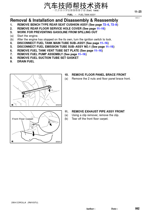
110FE–01A65046A65047Front Floor Carpet –FUEL FUEL TANK ASSY11–25992AuthorĂ:DateĂ:2004 COROLLA (RM1037U)Removal & Installation and Disassembly & Reassembly1.REMOVE BENCH TYPE REAR SEAT CUSHION ASSY (See page 72–6, 72–8)2.REMOVE REAR FLOOR SERVICE HOLE COVER (See page 11–16)3.WORK FOR PREVENTING GASOLINE FROM SPILLING OUT(a)Start the engine.(b)After the engine has stopped on the its own, turn the ignition switch to lock.4.DISCONNECT FUEL TANK MAIN TUBE SUB–ASSY (See page 11–16)5.DISCONNECT FUEL EMISSION TUBE SUB–ASSY NO.1 (See page 11–16)6.REMOVE FUEL TANK VENT TUBE SET PLATE (See page 11–16)7.REMOVE FUEL PUMP ASSEMBLY (See page 11–16)8.REMOVE FUEL SUCTION TUBE SET GASKET9.DRAIN FUEL10.REMOVE FLOOR PANEL BRACE FRONT(a)Remove the 2 nuts and floor panel brace front.11.REMOVE EXHAUST PIPE ASSY FRONT(a)Using a clip remover, remove the clip.(b)Tear off the front floor carpet.汽车技师帮技术资料一汽丰田卡罗拉维修维修手册(fuel tank)A65706A65049A6505011–26–FUEL FUEL TANK ASSY993AuthorĂ:DateĂ:2004 COROLLA (RM1037U)(c)Disconnect the oxygen sensor connector.(d)Remove the 2 exhaust pipe supports.(e)Remove the 4 bolts, 4 compression springs and exhaustpipe.12.REMOVE FUEL TANK PROTECTOR NO.1(a)Remove the 5 bolts and fuel tank protector.13.SEPARATE PARKING BRAKE CABLE ASSY NO.2(a)Remove the 2 installing bolts of the parking brake cable.汽车技师帮技术资料一汽丰田卡罗拉维修维修手册(fuel tank)A65051A65052A66709Nylon Tube Fuel TubeConnector Clip Pipe O–ring Fuel Tube Connector A65054A65055–FUEL FUEL TANK ASSY 11–27994AuthorĂ:DateĂ:2004 COROLLA (RM1037U)14.SEPARATE PARKING BRAKE CABLE ASSY NO.3(a)Remove the 2 installing bolts of the parking brake cable.15.DISCONNECT FUEL TANK MAIN TUBE SUB–ASSY (a)Pinch the fuel tube connector clip, and remove the fuel tube connector clip.(b)Pull out the fuel tank main tube.NOTICE:S Check if there is any dirt like mud around the fuel tube connector before this work and clean the dirt away.S Be careful of dirt like mud because the fuel tube con-nector has an O–ring to seal the fuel tube connector and pipe.S Do not use any tool in this work.S Do not bend or twist the nylon tube by force.S After disconnecting, cover the fuel tube connector with a vinyl bag.S When the fuel tube connector and pipe are stuck,pinch the fuel tank main tube between fingers, and turn it carefully to free and then disconnect the fuel tank main tube.16.DISCONNECT FUEL TANK INLET PIPE FUEL HOSE (a)Disconnect the fuel tank inlet filler pipe hose from the fuel tank.17.DISCONNECT FUEL TANK BREATHER HOSE (a)Disconnect the fuel tank breather hose from the fuel tank.汽车技师帮技术资料一汽丰田卡罗拉维修维修手册(fuel tank)A65056Push Pinch A A PinchA65057A65058A65059Nylon Tube Fuel TubeConnector ClipPipe O–ring Fuel Tube Connector A6506011–28–FUEL FUEL TANK ASSY 995AuthorĂ:DateĂ:2004 COROLLA (RM1037U)18.DISCONNECT FUEL TANK VENT HOSE (a)Disconnect the fuel tank bent hose from the charcoal can-ister.(1)Push the connector deep inside.(2)Pinch portion A.(3)Pull out the connector.19.DISCONNECT VALVE TO FUEL FILLER PIPE HOSE (a)Disconnect the valve to fuel filler pipe hose from the fuel tank inlet pipe.20.DISCONNECT FUEL EMISSION TUBE SUB–ASSY NO.1(a)Pinch the fuel tube connector clip and then pull out the fuel emission tube.NOTICE:S Check if there is any dirt like mud around the fuel tube connector before this work and clean the dirt away.S Be careful of dirt like mud because the fuel tube con-nector has an O–ring to seal the fuel tube connector and pipe.S Do not use any tool in this work.S Do not bend or twist the nylon tube by force.S After disconnecting, cover the fuel tube connector with a vinyl bag.S When the fuel tube connector and pipe are stuck,pinch the fuel emission tube between fingers, and turn it carefully to free and then disconnect the fuel emission tube.21.REMOVE FUEL TANK ASSY (a)Set a mission jack to the fuel tank.(b)Remove the 4 bolts, 2 fuel tank bands and fuel tank.汽车技师帮技术资料一汽丰田卡罗拉维修维修手册(fuel tank)A65061A65062A65063A65064A60576Nylon TubeFuel TubeConnector ClipPipe O–ring Fuel TubeConnector –FUEL FUEL TANK ASSY 11–29996AuthorĂ:DateĂ:2004 COROLLA (RM1037U)22.REMOVE FUEL TANK MAIN TUBE SUB–ASSY (a)Remove the fuel tank main tube from the fuel tube clamp and bracket.23.REMOVE FUEL TUBE CLAMP NO.4(a)Remove the bolt and fuel tank clamp.24.REMOVE FUEL TUBE BRACKET (a)Remove the fuel tube bracket from the fuel tank.25.REMOVE FUEL EMISSION TUBE SUB–ASSY NO.1(a)Pinch the fuel tube connector clip and then pull out the fuel emission tube.NOTICE:S Check if there is any dirt like mud around the fuel tube connector before this work and clean the dirt away.S Be careful of dirt like mud because the fuel tube con-nector has an O–ring to seal the fuel tube connector and pipe.S Do not use any tool in this work.S Do not bend or twist the nylon tube by force.S After disconnecting, cover the fuel tube connector with a vinyl bag.S When the fuel tube connector and pipe are stuck,pinch the fuel emission tube between fingers, and turn it carefully to free and then disconnect the fuel emission tube.汽车技师帮技术资料一汽丰田卡罗拉维修维修手册(fuel tank)A65065A65066A65067Clip Remover Gasket A6506811–30–FUEL FUEL TANK ASSY 997AuthorĂ:DateĂ:2004 COROLLA (RM1037U)26.REMOVE FUEL TUBE CLAMP NO.2(a)Remove the fuel tube clamp from the fuel tank.27.REMOVE CHECK VALVE PROTECTOR (a)Using a screwdriver, unlock the claw, and remove the check valve protector by turning it counter clockwise.28.REMOVE FUEL TANK INLET VALVE ASSY (a)Insert a clip remover between the fuel tank inlet valve and gasket, remove the fuel tank inlet valve by gradually pushing it upward.NOTICE:S Work accurately to maintain the sealing performance of the fuel tank inlet valve, since it is made from resin.It is easy to damage by removing and installing forci-bly.S Be sure to install a new fuel tank inlet valve and gas-ket.29.REMOVE CHECK VALVE GASKET (a)Remove the gasket from the fuel tank inlet valve.汽车技师帮技术资料一汽丰田卡罗拉维修维修手册(fuel tank)A65069A65069A65070A65071Apply a light coatof oil–FUEL FUEL TANK ASSY 11–31998AuthorĂ:DateĂ:2004 COROLLA (RM1037U)30.REMOVE FUEL TANK CUSHION NO.1(a)Remove the 7 fuel tank cushions from the fuel tank.31.INSTALL FUEL TANK CUSHION NO.1(a)Install the 7 new fuel tank cushions to the fuel tank.32.INSTALL CHECK VALVE GASKET (a)Install a new gasket to the fuel tank.33.INSTALL FUEL TANK INLET VALVE ASSY (a)Apply a light coat of oil around the fuel tank inlet valve asshown in the illustration, and insert it into the fuel tankwithout force.NOTICE:Be careful not to drop the gasket into the fuel tank.34.INSTALL FUEL EMISSION TUBE SUB–ASSY NO.1(a)Push in the fuel tube connector to the pipe until fuel tube connector makes ”click” sound.NOTICE:S Check if there is any damage or foreign objects on the connected part.S After connecting, check if the fuel tube connector and pipe are securely connected by pullingthem.35.INSTALL FUEL TUBE CLAMP NO.4(a)Install the fuel tube clamp with the bolt.Torque: 6.0 N ⋅m (61 kgf ⋅cm, 53 in.⋅lbf)汽车技师帮技术资料一汽丰田卡罗拉维修维修手册(fuel tank)A51891Tail Pipe Side Gasket –FUEL FUEL TANK ASSY 11–331000AuthorĂ:DateĂ:2004 COROLLA (RM1037U)(c)Install a new gasket on the exhaust pipe (rear side).(d)Install the exhaust pipe with the 4 compression springsand 4 bolts.Torque: 43 N ⋅m (440 kgf ⋅cm, 32 ft ⋅lbf)(e)Install the 2 exhaust pipe supports.(f)Connect the oxygen sensor connector.(g)Install the font floor carpet with a clip.43.INSTALL FLOOR PANEL BRACE FRONT(a)Install the floor panel brace front with the 2 nuts.Torque: 30 N ⋅m (302 kgf ⋅cm, 22 ft ⋅lbf)44.INSTALL FUEL SUCTION TUBE SET GASKET (See page 11–16)45.INSTALL FUEL PUMP ASSEMBLY (See page 11–16)46.INSTALL FUEL TANK VENT TUBE SET PLATE (See page 11–16)47.CONNECT FUEL EMISSION TUBE SUB–ASSY NO.1 (See page 11–16)48.CONNECT FUEL TANK MAIN TUBE SUB–ASSY (See page 11–16)49.CHECK FUEL LEAK (See page 11–1)50.CHECK EXHAUST GAS LEAK51.INSTALL REAR FLOOR SERVICE HOLE COVER (See page 11–16)52.INSTALL BENCH TYPE REAR SEAT CUSHION ASSY (See page 72–6, 72–8)汽车技师帮技术资料一汽丰田卡罗拉维修维修手册(fuel tank)。
《丰田卡罗拉自动变速器的故障诊断与维修开题报告2300字》

4.2017.8.07—8.10进行任务设计,实现任务的功能要求。
5.2017.8.11—8.21撰写毕业设计说明书,提交毕业设计说明书初稿,并根据指导老师的意见和建议进行修改。
6.2017.8.22—8.23提交毕业设计说明书终稿,准备毕业设计答辩。
2.3提出方案,解决变速器漏油的问题。
2.4提出方案,解决自动变速器内部打滑的问题;
三、研究方法及措施
1研究方法
根据丰田卡罗拉U341E型自动变速器故障的典型事例,对丰田卡罗拉U341E型自动变速器的换挡冲击并采取了有效的原因以及维修方法。最后,给出了丰田卡罗拉U341E型车型自动变速器无法正常挂入R挡方案。
五、主要参考文献(其中外文文献不少于2篇)
[1]张红卫,程文浩.汽车自动变速器常见故障的检测与维修讨论[J].科技展望.2017(21)
[2]姜勇.汽车自动变速器故障诊断及其排除方法探讨[J].现代交际.2016(11)
[3]解振宇.汽车自动变速器翻转架卡具的改进[J].农机使用与维修.2014(06)
2国内研究状况
国内汽车产业虽然取得了比较大的进步,产品的国际竞争力不断提高,然而一些核心技术与国外仍然存在比较大的差距。其中自动变速器便是其一。由于尚未实现真正的产业化,尚处在受制于人的局面。液力自动变速器已有60多年的历史,技术成熟、性能可靠,目前国外轿车上普遍使用的是AT,并且AT也几乎成为自动变速器的代名词。针对我国汽车产业现状,发展AMT技术,一方面可以甩开自动变速器的生产弱势,充分利用现有的已经很成熟的机械变速器产业达到自动操纵;另一方面能避开传统AT技术耗油量太高的缺点,达到能效与自动的双赢。发展AMT的好处,是保护国内的汽车产业安全。目前国内汽车整车产业看上去发展势头很好,但部件生产却没有跟上,一些最核心的部件仍然依赖进口,最关键的技术不在我们的掌握之中,使我们的产业链相当脆弱。现在,国内AMT技术的研究并不比国外差,只要抓住时机,尽快制定产业标准,我们就将拥有自主知识产权的AMT产业。
丰田 英文说明书

丰田英文说明书Toyota Owner's ManualThank you for choosing Toyota! This owner's manual is designed to help you get the most out of your Toyota vehicle. Please read it carefully and follow the instructions to ensure safe and enjoyable driving experience.Safety Precautions- Always wear your seatbelt and ensure all passengers do the same.- Follow all traffic laws and regulations.- Do not use your phone or engage in distracting activities while driving.- Keep a safe distance from other vehicles and drive at a safe speed.Vehicle Operation- Familiarize yourself with the location and operation of all controls, including lights, wipers, and audio system.- Understand the use of the transmission, parking brake, and cruise control system.- Learn how to properly maintain and care for your vehicle, including checking fluid levels and tire pressure.Maintenance and Service- Follow the recommended maintenance schedule provided in the manual.- Use only genuine Toyota parts and fluids for repairs and maintenance.- Keep a record of all maintenance and service performed on your vehicle.Troubleshooting- If you encounter any issues with your vehicle, refer to the troubleshooting section of the manual.- If you are unable to resolve the issue on your own, contact your authorized Toyota dealer for assistance.Warranty Information- Familiarize yourself with the terms and conditions of your vehicle's warranty.- Follow the recommended maintenance schedule to ensure the warranty remains valid.Driving Tips- Use the eco-driving mode to maximize fuel efficiency.- Practice smooth acceleration and braking to improve fuel economy.- Avoid excessive idling and aggressive driving habits.Entertainment and Connectivity- Learn how to use the audio system, Bluetooth connectivity, and other entertainment features.- Familiarize yourself with the navigation system if equipped.We hope this manual will provide you with the information you need to enjoy your Toyota vehicle to the fullest. If you have any questions or need further assistance, please contact your authorized Toyota dealer.感谢您选择丰田!本使用手册旨在帮助您充分了解您的丰田车辆。
教学设计(诊断与排除丰田COROLLA自动变速器不升档故障
教案课程名称:汽车自动变速器故障诊断与排除学习任务:丰田COROLLA自动变速器(U340E)不升档故障的诊断与排除授课班级:任课教师:学习任务名称诊断与排除丰田COROLLA自动变速器不升档故障课程名称汽车自动变速器故障诊断与排除教学对象汽车检测与维修专业预备技师阶段学生课时20课时设计者一、教学内容分析《汽车自动变速器故障诊断与排除》是汽车检测与维修专业预备技师层次的一门专业核心课程。
学习完成本课程后,学生应当能诊断与排除自动变速器常见故障。
本课程是通过企业调研,召开企业实践专家访谈会,对企业典型工作任务提取而获得,是企业中最常见的任务之一,具有代表性,典型性。
根据企业对不同层次人才的技能要求,我们将自动变速器学习分为三个层次:初中级水平层次《汽车自动变速器维修》;高级水平层次《汽车自动变速器大修》;预备技师水平层次《汽车自动变速器故障诊断与排除》。
其中,初中级水平《汽车自动变速器维修》包括三个学习任务:学习任务一:汽车自动变速器维护学习任务二:汽车自动变速器性能测试学习任务三:汽车自动变速器漏油的检修高级水平《汽车自动变速器大修》包括四个学习任务:学习任务一:分解汽车自动变速器学习任务二:清洗检测汽车自动变速器各部件学习任务三:组装汽车自动变速器学习任务四:测试自动变速器性能(综合测试仪)技师水平《汽车自动变速器故障诊断与排除》包括四个学习任务:(见附件4)学习任务一:诊断与排除自动变速器打滑的故障学习任务二:诊断与排除自动变速器换挡冲击大的故障学习任务三:诊断与排除自动变速器不升档的故障学习任务四:诊断与排除自动变速器异响的故障本次课是技师水平层次的学习任务三《诊断与排除自动变速器不升档的故障》其中的参考性学习任务:诊断与排除丰田COROLLA自动变速器不升档的故障。
通过本次课学习,要求学生能够确认自动变速器不升档现象,查阅维修手册等相关资料,正确编制故障排除计划,根据计划排除故障。
根据这一目标,对教学内容做如下处理:(1)以《诊断与排除丰田COROLLA自动变速器不升档故障》的工作页作为学习任务书,指引学生实现“学习的内容就是工作,通过工作实现学习”的目的。
- 1、下载文档前请自行甄别文档内容的完整性,平台不提供额外的编辑、内容补充、找答案等附加服务。
- 2、"仅部分预览"的文档,不可在线预览部分如存在完整性等问题,可反馈申请退款(可完整预览的文档不适用该条件!)。
- 3、如文档侵犯您的权益,请联系客服反馈,我们会尽快为您处理(人工客服工作时间:9:00-18:30)。
2004款丰田卡罗拉自动变速器系统维修手册(英文版) 40–1AUTOMATIC TRANSMISSION TRANS –AUTOMATIC TRANSAXLE ASSY ATMAUTOMATIC TRANSAXLE ASSY ATM400LF–01PRECAUTION1 The automatic transaxle is composed of highly precision–finished parts necessitating carefulinspection before reassembly because even a small nick could cause fluid leakage or affectthe performance The instructions here are organized so that youwork on only one componentgroup at a time This will help avoid confusion from similar–looking parts of different sub–as-semblies being on your workbench at the same time The component groups are inspected andrepaired from the converter housing side As much as possible complete the inspection repairand reassembly before proceeding to the next component group If a defect is found in a certaincomponent group during reassembly inspect and repair this group immediately If a compo-nent group cannot be assembled because parts are being ordered be sure to keep all parts ofthe group in a separate container while proceeding with disassembly inspection repair andreassembly of other component groupsRecommended ATF T–IV2 All disassembled parts should be washed clean and any fluid passages and holes should beblown through with compressed air3 Dry all parts with compressed air–never use shop rags4 When using compressed air always aim away from yourself to prevent accidentally sprayingATF or kerosene on your face5 The recommended automatic transaxle fluid or kerosene should be used for cleaning6 After cleaning the parts should be arranged in the correct order for efficient inspection repairsand reassembly7 When disassembling a valve body be sure to match each valve together with the correspond-ing spring8 New discs for the brakes and clutches that are to be used for replacement must be soaked inATF for at least 15 minutes before reassembly9 All oil seal rings clutch discs clutch plates rotating parts and sliding surfaces should becoated with ATF prior to reassembly10 All gaskets and rubber O–rings should be replaced11 Do not apply adhesive cements to gaskets and similar parts12 Make sure that the ends of a snap ring are not aligned with one of the cutouts and are installedin the groove correctly13 If a worn bushing is to be replaced the sub–assembly containing the bushing must also be re-placed14 Check thrust bearings and races for wear or damage Replace if necessary15 Use petroleum jelly to keep parts in place16 When working with FIPG material you must observe the followingUsing a razor blade and a gasket scraper remove all the old packing FIPG material from thegasket surfaceThoroughly clean all components to remove all the loose materialClean both sealing surfaces with a non–residue solventParts must be reassembled within 10 minutes of application Otherwise the packing FIPG ma-terial must be removed and reapplied2004 COROLLA RM1037U135140–2AUTOMATIC TRANSMISSION TRANS –AUTOMATIC TRANSAXLE FLUID ATMAUTOMATIC TRANSAXLE FLUID ATM400LG–01ON–VEHICLE INSPECTION1 CHECK THE FLUID LEVELHINTDrive the vehicle so that the engine and transaxle are at normaloperating temperatureFluid temperature 70 – 80 C 158 – 176 FOK if hot a Park the vehicle on a level surface and set the parkingAdd if hot b With the engine idling and the brake pedal depressedshift the shift lever into all ranges from P to L position andreturn to P positionc Pull out the dipstick and wipe it cleand Push it back fully into the pipee Pull it out and check that the fluid level is in the HOT posi-D25120 tionleaks it is necessary to repair or replace O–ringsFIPGs oil seals plugs or other parts2004 COROLLA RM1037U135240–3AUTOMATIC TRANSMISSION TRANS –PARKNEUTRAL POSITION SWITCH ASSY ATMPARKNEUTRAL POSITION SWITCH ASSY ATM400LH–01REPLACEMENT1 REMOVE BATTERY2 REMOVE BATTERY CARRIERa Remove the 4 bolts and battery carrierC801593 DISCONNECT FLOOR SHIFT CABLE TRANSMISSIONCONTROL SHIFTa Remove the nut from the control shaft leverbDisconnect the control cable from the control shaft leverc Remove the clip and disconnect the control cable fromthe control cable bracketC961474 REMOVE PARKNEUTRAL POSITION SWITCH ASSYa Disconnect the parkneutral position switch connectorb Remove the nut washer and control shaft leverc Pry out the lock plate and remove the manual valve shaftnutd Remove the 2 bolts and pull out the parkneutral positionswitchD251245 INSTALL PARKNEUTRAL POSITION SWITCH ASSYa Install the parkneutral position switch to the manual valveshaftb Temporarily install the 2 boltsc Place a new lock plate and tighten the nutTorque55 Nm 56 kgfcm 49 inlbfdTemporarily install the control shaft leverD099572004 COROLLA RM1037U135340–4AUTOMATIC TRANSMISSION TRANS – PARKNEUTRAL POSITION SWITCH ASSY ATMeTurn the lever counterclockwise until it stops then turn itclockwise 2 notchesf Remove the control shaft leverD25126g Align the groove with neutral basic lineNeutralh Hold the switch in position and tighten the 2 boltsBasic LineTorque 55 Nm 56 kgfcm 49 inlbfGrooveD08584i Using a screwdriver stake the nut with the lock plateD08585j Install the control shaft lever washer and nutTorque 125 Nm 127 kgfcm 9 ftlbfk Connect the parkneutral position switch connectorD251256 INSTALL FLOOR SHIFT CABLE TRANSMISSIONCONTROL SHIFTa Temporarily install the control cable to the control shaft le-ver with nutb Install the control cable and clip to the bracketC961472004 COROLLA RM1037U135440–5AUTOMATIC TRANSMISSION TRANS –PARKNEUTRAL POSITION SWITCH ASSY ATM7 INSTALL BATTERY CARRIERa Install the battery carrier and 4 boltsTorque 13 Nm 132 kgfcm 10 ftlbfC801598 ADJUST SHIFT LEVER POSITION See page 40–449 INSPECT SHIFT LEVER POSITION See page 40–4410 INSPECT PARKNEUTRAL POSITION SWITCH ASSY See page 40–62004 COROLLA RM1037U135540–6AUTOMATIC TRANSMISSION TRANS –PARKNEUTRAL POSITION SWITCH ASSY ATM400LI–01ADJUSTMENT1 INSPECT PARKNEUTRAL POSITION SWITCH ASSYa Apply the parking brake and turn the ignition switch ONb Depress the brake pedal and check that the engine starts only when the shift lever is set in N or P posi-tion and it does not start in the other positionc Check that the back–up light comes on and the reverse warning buzzer sounds only when the shiftlever is set in R position and these do not function in the other positionsIf a failure is found check the park neutral position switch for continuity2 ADJUST PARKNEUTRAL POSITION SWITCH ASSYa Loosen the 2 bolts of park neutral position switch and setNeutralBasic Line the shift lever to the N positionb Align the groove and neutral basic linec Hold the switch in position and tighten the 2 boltsTorque 55 Nm 56 kgfcm 49 inlbfd After adjustment perform the inspection described inGroovestep1D255142004 COROLLA RM1037U135640–7AUTOMATIC TRANSMISSION TRANS – AUTOMATIC TRANSAXLE ASSY ATMAUTOMATIC TRANSAXLE ASSY ATM400LJ–01COMPONENTSHood Sub–assyAir Cleaner Assy13 132 1070 71 62 inlbf70 71 62 inlbfBatteryCylinder HeadCover No2 12 122 91275 130 913 132 1010 102 7Control Cable Support255 260 19StarterAssy39 400 2913 132 10 wo ABSOil Cooler Inlet Tube No1Oil Cooler OutletTube No1 39 400 29 13 132 10Floor ShiftCable Transmission345 350 25Control Shift55 56 49 inlbfClipSpeedometer sensorTransmission Oil Filler connectorTube Sub–assy55 56 49 inlbf Battery Carrier12 1229 Automatic Transaxle AssyO–ringATF Level Gauge12 122 9 Transmission Control CableNm kgfcm ftlbf Specified torque Bracket No1Non–reusable part C953482004 COROLLA RM1037U135740–8AUTOMATIC TRANSMISSION TRANS– AUTOMATIC TRANSAXLE ASSY ATM80 815 59Front Drive Shaft Assy RH52 530 3852 530 38Snap Ring Engine MountingBracket LHTorque Converter Clutch Assy64 65047 Engine Mounting52 530 38Insulator LHx 646 470 3428 285 20Snap Ring23 235 17 Front Drive Shaft Assy LHFlywheel Housing Under CoverTransmission Case Protector18 182 14Automatic Transaxle AssyEngine Mounting Insulator RREngine Mounting 87 887 64Bracket RR 64 652 47Engine Mounting Bracket FR64 652 47Engine Under Cover RH52530 3852 530 38Engine Under Cover LH 64 652 4764 652 4752 530 38FrontSuspension Member DynamicDamper52 530 38Engine Mounting MemberSub–assy CenterNm kgfcm ftlbf Specified torque 39 398 29Non–reusable part C953492004 COROLLA RM1037U135840–9AUTOMATIC TRANSMISSION TRANS –AUTOMATIC TRANSAXLE ASSY ATM400LK–02REPLACEMENT1 REMOVE HOOD SUB–ASSY2 REMOVE CYLINDER HEAD COVER NO23 REMOVE BATTERY4 REMOVE BATTERY CARRIERa Remove the4 bolts and battery carrierC801595 REMOVE AIR CLEANER ASSEMBLY WITH HOSE6 REMOVE FLOOR SHIFT CABLE TRANSMISSIONCONTROL SHIFTa Remove the nut from the control shaft leverb Disconnect the control cable from the control shaft leverc Remove the clip and disconnect the control cable fromthecontrol cable bracketC961477 REMOVE TRANSMISSION CONTROL CABLESUPPORTa Disconnectthe wire harness clamp and control cablefrom thecontrol cable supportb Remove thebolt and control cable supportC957508 REMOVE TRANSMISSION CONTROL CABLE BRACKET NO1a Remove the 2 bolts and control cable bracket2004 COROLLA RM1037U135940–10AUTOMATIC TRANSMISSION TRANS –AUTOMATIC TRANSAXLE ASSY ATM9 DISCONNECT WIRE HARNESSa Remove the2 bolts and disconnect the 2 wire harnessesb Remove the bolt and disconnect the wire harness clampbracketC93666c Remove thebolt and disconnect the wire harness clampbracketC9364310 DISCONNECT CONNECTORa Disconnect the transmission wire connectorb Disconnect the parkneutral position switch connectorc wo ABSDisconnect the speedometer sensor connector11 REMOVE TRANSMISSION OIL FILLER TUBESUB–ASSYa Remove the ATF lever gaugeb Remove the 2 bolts oil cooler tube clamp and oil fillertubec Remove theO–ring from the oil filler tubeD0996112 DISCONNECT OIL COOLER INLET TUBE NO1a Using SST disconnect the oil cooler inlet tube No 1SST 09023–12700SSTC9364613 DISCONNECT OIL COOLER OUTLET TUBE NO1a Using SST disconnect the oil cooler outlet tube No 1SST 09023–127002004 COROLLA RM1037U136040–11AUTOMATIC TRANSMISSION TRANS –AUTOMATIC TRANSAXLE ASSY ATM14 DISCONNECT OXYGEN SENSOR CONNECTORa Remove the foot restb Pull up the floor carpetc Disconnect the oxygen sensor connectorNo 1 No 2 15 SUSPEND ENGINE ASSYEngine Hanger Engine Hanger a Disconnect the 2 PCV hosesb Install the No1 and No2 engine hangers in the correctdirectionParts NoNo1 engine hanger 12281–22021No2 engine hanger 12281–15040Bolt91512–B1016Front Rear D25372 Torque 38 Nm 387 kgfcm 28 ftlbfc Attach the engine chain hoist to the engine hangersCAUTIONDo not attempt to hang the engine by hooking the chain toany other parts16 REMOVE FRONT WHEELS17 REMOVE ENGINE UNDER COVER RH18 REMOVE ENGINE UNDER COVER LH19 DRAIN AUTOMATIC TRANSAXLE FLUIDa Remove the drain plug and gasket and drain ATFb Install a new gasket and drain plugTorque 175 Nm 178 kgfcm 13 ftlbf20 REMOVE EXHAUST PIPE ASSY FRONT See page 15–221 REMOVE FRONT DRIVE SHAFT ASSY RH See page 30–6SST 09520–01010 09520–24010 09520–32040 22 REMOVE FRONT DRIVE SHAFT ASSY LH See page 30–6SST 09520–01010 09520–24010 09520–3204023 REMOVE AUTOMATIC TRANSMISSION CASE PROTECTORa Remove the 2 bolts and case protector24 REMOVE STARTER ASSYa Remove the nut and disconnect the starter wireb Disconnect the connectorc Remove the 2 bolts and starter25 SUPPORT AUTOMATIC TRANSAXLE ASSYa Support the automatic transaxle with a transmission jack26 REMOVE TRANSVERSE ENGINE ENGINEMOUNTINGINSULATORa Remove the 5bolts nut and engine mounting insulatorLHD099642004 COROLLA RM1037U136140–12AUTOMATIC TRANSMISSION TRANS –AUTOMATIC TRANSAXLE ASSY ATM27 REMOVE TRANSVERSE ENGINE ENGINEMOUNTINGBRACKETa Remove the3 bolts and engine mounting bracket LHD0996528 REMOVE TRANSVERSE ENGINE ENGINEMOUNTING INSULATORa Remove thebolt from the engine mounting bracket RRC80192b Remove the3 nuts bolt and engine mounting insulatorRR from the suspension memberC8016729 REMOVE TRANSVERSE ENGINE ENGINEMOUNTING INSULATORa Remove thebolt and nut from the engine mounting brack-et FRC8016630 REMOVEENGINE MOUNTING MEMBER SUB–ASSYCENTERa Remove the4 bolts dynamic damper and member sub–assycenter with engine mounting insulator FRC953542004 COROLLA RM1037U136240–13AUTOMATIC TRANSMISSION TRANS –AUTOMATIC TRANSAXLE ASSY ATM31 REMOVETRANSVERSE ENGINE ENGINEMOUNTINGBRACKETa Remove the 2bolts and engine mounting bracket FRC8017232 REMOVE TRANSVERSE ENGINE ENGINEMOUNTINGBRACKETa Remove the 3bolts and engine mounting bracket RRC9364533 REMOVE FLYWHEEL HOUSING UNDER COVER34 REMOVE AUTOMATIC TRANSAXLE ASSYa Turn the crankshaft to gain access and remove the 6 boltswhile holding the crankshaft pulley bolt with a wrenchF00478b Remove the 6 boltsc Separate and remove the automatic transaxleD0996635 REMOVE TORQUE CONVERTER CLUTCH ASSY36 INSPECT TORQUE CONVERTER CLUTCH ASSY See page 40–20SST 09350–32014 09351–32010 09351–320202004 COROLLA RM1037U136340–14AUTOMATIC TRANSMISSION TRANS –AUTOMATIC TRANSAXLE ASSY ATM37 INSTALL TORQUE CONVERTER CLUTCH ASSYa Install the torque converter clutch to the automatic trans-axleb Using vernier calipers measure the dimension A be-tweenthe transaxle fitting part and the converter fittingpart of the drive plateC63993c Using vernier calipers and a straight edge measure thedimension B shown in the illustration and check that Bisgreater than A measured in bStandardA 1 mm or moreNOTICEDo not add the thickness of straight edgeC6591138 INSTALL AUTOMATIC TRANSAXLE ASSYa Install the automatic transaxle and 6 bolts to the engineTorqueABolt A 64 Nm 650 kgfcm 47 ftlbfB Bolt B。