闪电王使用说明
W-Ape ApeLight Maxi 说明书

Table of ContentsSafety Instructions (1)Warning (2)General (3)Operation (4)Turn On and Off (4)Assignment of a Group (5)Using the Remote Control (5)List of Programs (7)Battery State/Charging (8)Disabling of the Battery Status Indicator (9)Enabling of the Battery Status Indicator (9)W-Ape Transceiver (10)Group (10)Control Mode (10)More Functions and Updates (12)Pairing (12)Pairing an ApeRemote with a Fixture: (12)Reset or Update of Firmware (13)Troubleshooting (14)Disposal (16)DMX Modes/DMX Sheets (17)3 Channel Mode (17)4 Channel Mode (18)8 Channel Mode (19)Safety Instructions›The ApeLight Maxi generates heat during operation and while charging. Therefore, make sure there is adequate ventilation and do not cover the light.›If you charge the ApeLight Maxi in the Tourcase (optional), the ApeLight Maxi Tourcase must remainopen.›Do not use the ApeLight Maxi in areas where the use of radio equipment is prohibited.›Do not look directly into the LEDs. This can cause damage to the eyes.Warning›All ApeLabs products use the same charging/power cord.Ape Labs products are specifically designed andengineered based on the Ape Labs power source (ApeLabs PSU). Do not use a different charging/power cord to power or charge the units (other than the Ape Labscharging road cases or Ape Labs PSU). Using a different power source may void your warranty.General›The ApeLight Maxi has three power LEDs below the lenses.›This device has 20 built-in auto programs. (See “List of Programs” below for details). Scroll thru the differentpre-sets with the left and right buttons on theApeRemote. If you’re on a static color, the Speed Up/Slow Down buttons will control the strobe speed. Ifyou’re on a chase program, they will control the colorchanging speed. By default, the Speed is set to it’slowest setting, which stops the speed effect.›This device can be wirelessly controlled with either the ApeRemote or W-Ape Transceiver (in combination with your favorite DMX controller).›All Ape Labs fixtures can be mixed/matched and controlled in the same room with the same remote (or DMX controller). To control certain fixtures differentlyfrom others in the same room, address the fixtures at the time they are turned on. For use with the ApeRemote,each fixture can be assigned to one of four groups. (See “Operation” section below for details on setting thefixture group).›If more than four groups are needed in a room, additional remotes can be used to add four additionalgroups per remote, as long as the added remotes arepaired with the respective light fixtures. (“See PairingSection” for additional details)›For use with the W-Ape (and a DMX controller), each fixture can be assigned to a DMX-512 address. Bydefault, the device is set to DMX address one, but it can be assigned to any address when it is turned on by going into Set-Up mode on the W-Ape.›The device has a built-in microphone. It can be activated on the remote control to create sound active effects. OperationTurn On and Off›Press the button on the back of the ApeLight Maxi for about one second. The unit turns on and remembers the previously selected program/brightness.›To turn the device off, press the button again for about a second.Note: The ApeLight Maxi ignores very short presses of the power button to prevent unintentional operation.Assignment of a GroupEach Ape Labs lighting fixture can be assigned to a specific group (so certain fixtures can be controlled differently than others in the same room).›Immediately after turning the ApeLight Maxi on, the current group setting of the ApeLight Maxi flashes on the remote control. (Factory setting is group 1.)›While the group LED is flashing, tap the Group Button again to change groups. The selected group LED willchange as you tap the Group Button.Note: The remote control switches to a power-save mode after a few minutes and will not detect the power-on event of a ApeLight Maxi. Press any key of remote control to stop the power-save mode.Using the Remote Control›To select the group you’d like to control, tap the “Group”button until the group LED is lit up. To control all groups at once, press and hold the “Group” button until all four group LEDs light up.›Programs, brightness, speed and sound active mode can be controlled by the corresponding keys (see figure).List of ProgramsNo Program1 White2 Red3 Orange4 Amber5 Lime6 Green7 Green/Blue8 Blue/Green9 Blue10 Blue/Magenta11 Magenta12 Red/White13 Green/White14 Blue/White15 Red > Blue16 Magenta > White17 White > Blue18 Red/White > Green/White > Blue/White19 Amber > Magenta > Blue20 Rainbow (All Colors)Hint: A long press on the left arrow will provide a static white color. A long press on the right arrow will provide a rainbow program. A long press on “Slow Down” stops a flash effect/color change in a multi-color program and will stay on single color. A long press on “Speed Up” will toggle between colors in selected program. In a multi-color program, the “Slow Down” button will also provide a fade effect opposed to flash effect/color change. In the Rainbow Program, a flash effect/color change will not occur, only a fade effect or single random color. Battery State/Charging›If the brightness of the ApeLight Maxi is reduced to zero (by “Power” or ”Dimmer” button of the remote control), the fixture will show the battery state at low brightness: o LEDs glow green: battery level above 50%o LEDs glow red: battery level below 50%Note: The calculation of the battery level needs at least one full charge/discharge cycle.›If the battery is completely empty, the device will blink 3 times red and turn itself off. Connect the provided power supply (18V DC) or put the device into the Tourcase.›If the battery charge is dropped to extremely low, the fixture may not blink Red (or show any signs of charging) during the first two hours of charging.›The ApeLight Maxi flashes red while charging. As soon as the battery is fully charged, the device will flash green.›The device can also be used while a power supply is connected. The battery will charge very slowly. Disabling of the Battery Status IndicatorThe red/green glowing indicator of the battery level can be disabled.›Step 1: Press and hold the power button on fixture until it flashes blue/white (This is also placing the fixture into Service Mode).›Step 2: Remove the battery compartment out of the ApeRemote.›Step 3: Slide the battery compartment back into the remote while pushing the “flashlight” symbol. (Remote will be flashing red on groups 1 & 4).›Step 4: Push the “Dim” button on the remote.›Step 5: Press the power button on fixture one time. ›Step 6: Press the “Power” button on the remote. Enabling of the Battery Status Indicator›Step 1: Press and hold the power button on fixture until it flashes blue/white (This is also placing the fixture into Service Mode).›Step 2: Remove the battery compartment out of the ApeRemote.›Step 3: Slide the battery compartment back into the remote while pushing the “flashlight” symbol. (Remote will be flashing red on groups 1 & 4).›Step 4: Push the “Bright” button on the remote.›Step 5: Press the power button on fixture one time.›Step 6: Press the “Power” button on the remote.W-Ape TransceiverMultiple W-Apes can be used in the same room on different universes if they are set to different groups.W-Ape has the following built-in modes (selected withUp/Down buttons on left of unit). Pressing the +/- buttons on the right of the unit will scroll thru the different options of each mode. If a light fixture is in set-up mode with the W-Ape, the screen will display info for the light fixture rather than the W-Ape.Group›Use +/- buttons to select the specific group.Control Mode›Sound Master: While the W-Ape is set to Sound Master mode, it will use the internal mic built in to the W-Ape to sync the Sound Active feature among all light fixtures(instead of using the internal mic built in to each fixture).In this mode, units will be controlled with an ApeRemote, thru the W-Ape. This feature extends the wireless range on the remote from it’s rated 200ft range, to the W-Ape’s rated wireless range of 3,000ft.›DMX: To use DMX controller, set W-Ape to “DMX” and connect your DMX controller to W-Ape input with 3-pin DMX cable.›W-Ape (Receiver): If multiple W-Apes are being used in one room, some W-Ape’s can be set as a receiver. In this case, set W-Ape to “W-Ape (Reciever)” and connect a 3-pin DMX cable from the DMX output of the W-Ape to the DMX input of the light fixture (to wirelessly control afixture that does not have wireless DMX built-in, such asa fixture from a brand other than Ape Labs).Info›Battery: During set-up mode, this will display the precise battery level of each light fixture.›Serial: This will display the serial number of the fixture. ›Firmware: This will display the firmware version of the fixture.DMX Mode›During set-up mode with given fixture, this will let you select the number of DMX mode for the fixture.o Off: W-APE/DMX-Mode is not activated - the device is only controllable by the remote control o3C: 3 channels: Dimmer, Program, Speedo4C: 4 channels: Red, Green, Blue, White (each is 1-DMX channel/8 Bit)o8C: 8 channels: Red, Green, Blue, White (each is 2-DMX channels/16 Bit: coarse + fine)More Functions and UpdatesPairingApe Labs lights and ApeRemotes can be paired permanently to one another so that they will no longer synchronize with other fixtures. Pair as many lights to one remote as you would like. This will allow users to create up to four groups on one remote and up to four more groups on each additional remote that is being used at the same time. Pairing an ApeRemote with a Fixture:›Step 1: Remove battery from ApeRemote›Step 2: While holding down flashlight button, insert battery into ApeRemote (if done correctly, group 1 and group 4 will flash on remote).›Step 3: Turn on fixture with long press on power button(5 seconds – if done correctly, fixture will blink blue).›Step 4: Press Right Arrow button to pair remote and light.›Step 5: Turn light off then back on. It will now only be controlled with that specific remote.›Step 6: To unpair, follow steps 1-3, then press Left Arrow button to unpair.NOTE: In case you lose paired remote, any remote can be used to unpair fixtures.Reset or Update of FirmwarePress and hold the power button of the ApeLight Maxi for about 10 seconds. The device will restart and stay in update mode for about 15 seconds (flashes red). During this period, an update can be started. If no update occurs, the device will go back to normal function. You can find firmware updates at or at your dealer.TroubleshootingProblem PossibleReason SolutionApeLight Maxi is dimmed and flashes sometimes Soundactivemode isactive.Press the microphonebutton on the remotecontrol to deactivatesound active mode.ApeLight Maxi flashes slowly Regularflash effectLong press (2s) “SlowDown” on the remotecontrol, to reduce theeffect speed to 0.ApeLight Maxi flashes 3 times red and turns itself off BatteryemptyConnect the powersupply to charge thebattery.Problem PossibleReason SolutionApeLight Maxi cannot be turned on Powerbutton waspressed tooshortPress and hold the buttonfor about 1 secondBrightness isat lowestlevel.Press “Brighter” button onthe remote controlBattery isdeeplydischargedConnect the 18V powersupply or charge theApeLight Maxi in theTourcase. It may takeseveral hours until thecharge will startApeLight Maxi glows permanently red/green RegularbatterystatusindicatorThe battery status will beshown by a glow of LEDs.This feature can bedisabled. Instructions canbe found above in“Disabling of the BatteryStatus Indicator” sectionDisposalIf the ApeLight Maxi is to be put out ofoperation, take it to a local recycling facility for a disposal which is not harmful to the environment. Never throw used batteries or defective rechargeable batteries into the household disposal: Always take them to a special waste disposal (e. g. collecting container at your retailer).DMX Modes/DMX Sheets3 Channel Mode: Dimmer, Program, SpeedThis mode can be used with other Ape Labs products, i.e. LightCan, MobiLight4, ApeStick4, ApeLight ART, and ApeLight Mini.Ch DMX Function1 0 - 255 Dimmer 0 - 100%2 0 - 5 Prog 1 White with fadesteps of 6*Prog 2 - 19 ... with fade114 - 127 Prog 20 Rainbow with fade128 - 133 Prog 1 White without fadesteps of 6*Prog 2 - 19 ... without fade242 - 255 Prog 20 Rainbow without fade3 0 - 255 Prog Speed 0 - 100%* Channel 1: Program 1-20 without fade and 1-20 with fade start at DMX value 0, 6, 12, 18, 24, 30, 36, 42, 48, 54, 60, 66, 72, 78, 84, 90, 96, 102, 108, 114, 128, 134, 140, 146, 152, 158, 164, 170, 176, 182, 188, 194, 200, 206, 212, 218, 224, 230, 236, 242Mode)This is the default DMX mode.This mode can be used with other Ape Labs products, i.e. LightCan, ApeStick4, and ApeLight Mini.If your DMX controller has no matching profile, use a “Generic/RGBW LED 8 Bit”.Channel DMX Function1 0 - 255 red 0 - 100%2 0 - 255 green 0 - 100%3 0 - 255 blue 0 - 100%4 0 - 255 white 0 - 100%This mode can be used with other Ape Labs products, i.e. LightCan, ApeStick4,and ApeLight Mini.If your DMX controller has no matching profile, use a “Generic/RGBW LED 16 Bit.”Channel DMX Function1 0 - 255 red 0 - 100%2 0 - 255 red fine3 0 - 255 green 0 - 100%4 0 - 255 green fine5 0 - 255 blue 0 - 100%6 0 - 255 blue fine7 0 - 255 white 0 - 100%8 0 - 255 white fine。
神灯操作规程(3篇)

第1篇一、概述神灯作为一种高科技产品,广泛应用于家庭、医院、美容院等领域,具有治疗、保健、美容等多种功能。
为确保用户安全、有效地使用神灯,特制定本操作规程。
二、设备准备1. 检查神灯外观是否完好,电源线、治疗头等配件是否齐全。
2. 将神灯放置在平稳、干燥的桌面上,确保设备底部离地面至少10cm。
3. 连接电源线,确保电源插座符合国家标准。
三、操作步骤1. 开机:按下电源开关,等待神灯自检完成。
2. 选择功能:根据需要,选择相应功能,如治疗、保健、美容等。
3. 设置时间:根据治疗需求,设置治疗时间,一般建议每次治疗时间为20-30分钟。
4. 选择强度:根据个人承受能力,选择合适的强度,一般从低强度开始,逐渐增加。
5. 放置治疗头:将治疗头放置于需要治疗的部位,确保治疗头与皮肤接触紧密。
6. 启动治疗:按下启动按钮,开始治疗。
7. 治疗过程中,保持治疗头与皮肤接触紧密,避免移动。
8. 治疗结束后,关闭电源,拔掉电源线。
四、注意事项1. 使用神灯前,请详细阅读说明书,了解设备功能和使用方法。
2. 神灯治疗时,请确保治疗部位皮肤干燥、无破损。
3. 治疗过程中,如感觉不适,请立即停止治疗,并咨询专业人员。
4. 治疗部位周围禁止放置易燃、易爆物品。
5. 孕妇、心脏病患者、高血压患者等特殊人群请在医生指导下使用神灯。
6. 请勿将神灯用于治疗肿瘤、急性炎症等疾病。
7. 神灯使用过程中,请勿与他人接触,以免造成意外伤害。
8. 请勿长时间连续使用神灯,以免造成皮肤损伤。
9. 定期清洁神灯,保持设备卫生。
10. 非专业人员请勿自行拆卸、维修神灯。
五、维护与保养1. 神灯使用后,请将治疗头擦干净,并存放在干燥处。
2. 定期检查电源线、插座等配件,确保无破损、老化现象。
3. 如发现设备故障,请及时联系专业人员维修。
4. 神灯设备请勿长时间放置在潮湿、高温、阳光直射的环境中。
六、安全提示1. 使用神灯时,请确保周围环境安全,避免发生意外。
胜利仪器 VICTOR 328D .328E 双视场手机红外热成像仪产品使用说明书

目录产品简介 (1)产品特性 (2)规格 (3)APP功能介绍 (4)4.1界面简介 (4)4.2功能介绍 (5)4.2.1设置 (5)4.2.2超温告警 (6)4.2.3界面重置 (7)4.2.4拍照 (7)4.2.5录像 (8)4.2.6图库 (8)4.2.7色板 (9)4.2.8区域测温 (11)4.2.9显示模式 (11)4.2.10融合偏移调整 (14)4.2.11图像锁定和镜像 (14)4.2.12高温速查 (15)4.2.13温度锁定 (15)使用注意事项 (17)双视场手机红外热成像仪仪采用像元间距小、高分辨率的工业级红外探测器,搭配3.2mm 镜头,是一款高精度快响应的便携红外热成像分析仪,同时应用了一款可见光的相机用以辅助红外成像,相比较单红外的产品可以更加清晰的显示出被测物体。
产品轻巧便携、即插即用,配合定制专业级热像分析APP,可以连接安卓手机对目标物体进行红外观测及测温。
∙优质光学镜头搭配高分辨率红外热成像,可见光数字相机采用640x480辅助成像,成像效果出色;∙相比较传统的手机热像仪,更多支持可见光模式、多种可见光和红外融合模式的测温,图像效果更加清晰细腻;∙轻巧便携,配合手机APP使用,随时随地进行专业热成像分析;∙测温范围广:-15℃~600℃;∙支持高温警报,自定义警报门限值;∙支持显示自定义温度区间画面,高温区域显示使用场景众多;∙支持高低温追踪;∙支持添加点、线、矩形框进行区域测温,线和矩形框支持高低温追踪和高温报警;∙铝合金外壳,坚固耐用。
规格红外热成像分辨率256x192160x120工作波长8~14μm帧率25HzNETD<50mK@25℃镜头 3.2mm视场角56°x42°35°x27°测温范围-15℃~600℃测温精度±2℃或读数的±2%可见光分辨率640x480帧率25Hz软件功能(APP)温度测量支持高低温自动追踪、中心点测温、点测温、区域测温、线测温,温度范围查看图像显示模式支持可见光模式,多种可见光和红外融合模式,单红外模式显示。
闪电王产品使用说明说明书

闪电王产品使用说明版本:v2.1.14上海澎博网络数据信息咨询有限公司版权所有侵权必究目录软件概述 (1)1.1软件用途 (1)1.2软件运行 (1)1.3系统配置............................................. 错误!未定义书签。
使用入门 (1)2.1软件登录与退出 (1)2.2页面结构 (4)2.3资金状态栏 (6)2.4期权报价 (7)2.5期权策略分析 (9)2.6多窗口监控 (10)2.7自定义界面 (10)2.8窗口浮动 (13)基本功能 (14)3.1开仓 (14)3.2平仓 (18)3.3反手 (19)3.4锁仓 (20)3.5可撤单 (20)3.6改单 (21)高级功能 (22)4.1止损止盈 (22)4.2条件单 (27)4.3闪电手下单 (29)4.4快鼠下单 (31)4.5键盘下单 (33)工具 (35)5.1参数设置 (35)5.2交易日志 (49)扩展交易功能 (49)6.1查询 (49)6.2转帐 (50)6.3交易统计 (51)6.4行权 (53)6.5保证金监控中心 (55)附录 (55)7.1软件安装 (55)7.2软件卸载 (57)闪电王使用说明软件概述1.1软件用途我们一直致力于为广大期货投资者提供“直观、快速、简单”的投资工具,经过长期探索发现用户需求,汲取用户交易策略精华,潜心数载开发出以市场为目标,以用户为中心的优秀专业的交易前端——闪电王。
闪电王系统采用先进的技术架构、简单便捷的下单模式、灵活独特的界面设计、实时动态多窗口提示、自定义参数设置、闪电手下单、快鼠点价、自定义键盘键盘下单等功能,将在期货蓬勃发展的大潮中助您一臂之力。
1.2软件运行闪电王运行在PC及其兼容机上,使用Microsoft Windows简体中文操作系统,可以在Win7、win10等中文简体操作系统上运行。
使用入门2.1软件登录与退出2.1.1 软件登录点击桌面上的图标,即可调出闪电王登录界面,软件支持选择期货公司,如图所示:1 / 602 / 60登录初始化登录界面选择期货公司登录过程注意事项:1) 输入用户号后,如需避免以后登录时重复输入可将【保存用户号】选择打勾;1、选择服务器2、输入用户号、交易密码、验证码/动态密码3、点击登录2)输入交易密码时,为防止恶意软件盗取密码,请点击【软键盘】输入;3)安全方式分为验证码、动态密码两种,用户可根据具体情况选择输入;4)点击【登录】按钮,表明用户已了解并接受了免责条款;5)点击【登录】按钮后,将出现用户信息等提示确认窗口,若提示信息无误可点击【确定】;6)在登录界面中还提供了网络测速功能。
电王HW310发电电焊机使用说明书
!
� 直流电源断路器处在“开”上时,切不可拔下或插上插座。 � 本机直流电源绝对不可与其他电网连接,否则会引起触电、火灾或线路故障。 重 要
�
� 不可超负荷使用(3KW,13.7A)。 � 直流电源断路器自动跳闸时,务必进行检查,减少负荷后再使用。
7. 定期点检维护
为了保持本机的最高性能、安全、顺利、经济的使用,请按以下要领切实做 好日常的点检维护工作。 7-1 日常点检维护 1. 检查接线和螺栓连接部位有无松动、脱落。 2. 排净燃油箱内的垃圾。 3. 检查机油的油量和污浊程度。 4. 检查电瓶液面、接触和腐蚀情况。 5. 排除燃油滤芯中的水。 6. 检查各螺栓连接部位有无松动、脱落。 7-2 最初维护(使用 8 小时后)
-30 粘 度 (S A E 分类)
30
40
SAE10W—30 SAE15W—40
注
意
!
� 若不使用防噪火花塞,收音机等电气产品会出现干扰或杂音。 � 检查焊接端子以及各部件的紧固状况。若有松弛会引起剧热导致火灾。 7-5-1 空气滤芯的清扫 � 滤芯应取出清扫,如果特别脏应及时更换。 � 固定滤芯的蝶状螺丝必须旋紧,否则赃物吸入,会导致活塞磨损,引起出力不 足。 7-6 每 200 小时的维护 7-6-1 检查发电机的绝缘电阻 1. 把直流电负荷或焊接负荷卸下,再卸下电瓶。 2. 拆下连接发电机的所有接线。 3. 发电机的绝缘电阻:各线圈与机框架之间用 500V 的摇表,应测得 1MΩ 为正常。 危 险
前
言
首先,感谢您对本公司发电电焊机的厚爱。 这本《使用说明书》将告诉您怎样安全、正确的使用机器,所以,务请认真阅 读,在完全理解设定、运行、点检、维修的知识后再启动机器。 关于发动机部分的详细说明,请参照所附的《发动机说明书》。 以上《说明书》阅读后请妥善保存,以便随时查阅。由于机器的技术改良,会 有一些地方与说明书不一致,不再另作说明。如有疑问,请向本公司代理联系。
AvengerII SOLO、DUO、TRIO 双类型警示灯(带线)说明书
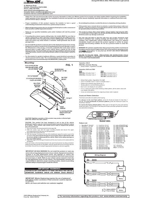
Avenger®II SOLO, DUO, TRIO Dual Dash Light (wired)CAUTION! Nighttime operation of this product may produce reflected light within the vehicle! Use with caution!CAUTION:This product has been designed to rest on top of the vehicle dashboard.Suction cups are used to prevent lateral movement while the vehicle is in motion.These suction cups should not be used to suspend this product above the dashboard.1.Secure the lower mounting bracket to theAvenger II®.2.Slide the suction cups onto the upper mounting bracket and secure the upper mounting bracket onto the lower mounting bracket.3.Secure the visor hood to the unit.4.With the Avenger II resting on the top of the dashboard,apply the suction cups to the windshield.Do not locate the Avenger II in any location where it will interfere with the drivers ability to safely operate the vehicle.Refer to the safety warnings on the cover of this manual.5.Adjust the angle of the Avenger II bracket until the visor hood is in full contact with the windshield.There are holes on the bail strap bracket to be used if permanent mounting is ing the bail strap bracket as a template,mark the areas where the mounting holes are to be drilled.Secure the unit using the appropriate hardware (customer supplied).For warranty information regarding this product, visit /warranty©2016 Whelen Engineering Company Inc.Form No. 14A22 (120916)Mounting:1.SignalAlert™CAL ALT2.SignalAlert™CAL SIMetFlash® 75ALTetFlash® 75 SIM5.DoubleFlash 75ALT6.DoubleFlash 75 SIM7.SingleFlash 75ALT8.SingleFlash 75 SIMAlert™75ALT Alert™75 SIM 11.LongBurst™75ALT 12.LongBurst™75 SIM 13.PingPong™75ALT 14.PingPong™75 SIM 15.SingleFlash 60ALT 16.SingleFlash 60 SIM 17.SingleFlash 90ALT 18.SingleFlash 90 SIM 19.SingleFlash 120ALT 20.SingleFlash 120 SIM21.SingleFlash 300ALT 22.SingleFlash 300 SIM 23.DoubleFlash 120ALT 24.DoubleFlash 120 SIM Alert™150ALT Alert™150 SIM 27.PingPong™120ALT 28.PingPong™120 SIM 29.TripleFlash™75ALT 30.TripleFlash™75 SIM 31.TripleFlash™120ALT 32.TripleFlash™120 SIM 33.ActionFlash™50ALT 34.ActionFlash™50 SIM 35.ActionFlash™150ALT 36.ActionFlash™150 SIM 37.SignalAlert 75ALT 38.SignalAlert 75 SIM 39.Action SF 60/120ALT 40.Action SF 60/120 SIM41.Action SF120/TF75ALT 42.Action SF120/TF75 SIM 43.CalScan™ALT 44.CalScan™SIM 45.ModuFlash™ALT 46.ModuFlash™SIM 47.ActionScan™ALT 48.ActionScan™SIM49.CAL CometFlash®ALT 50.CAL CometFlash® SIM 51.SteadyFlash™6052.SteadyFlash™7553.SteadyFlash™9054.SteadyFlash™12055.Steady & SteadyALT =Alternating SIM = Simultaneous BOLD = CA Title XIIIPattern ListSafety First: This document provides all the necessary information to allow your Whelen product to be properly and safely installed. Before beginning the installation and/or operation of your new product, the installation technician and operator must read this manual completely. Important information is contained herein that could prevent serious injury or damage.IMPORTANT AIR BAG WARNING!Do notinstall this product or route any wires in the air bag deployment zone of your vehicle.Equipment mounted or located in air bag deployment zones will damage or reduce the effectiveness of the air bag,or become a projectile that could cause serious personal injury or death.Refer to your vehicle owners manual to learn the air bag deployment zones for the vehicle.The User/Installer assumes full responsibility to determine proper mounting location,based on providing ultimate safety to all passengers inside the vehicle.Operation: SOLORED Wire:Activates Warning.•ALT Default Pattern: SignalAlert CAL Operation: DUO and TRIO DUOTRIORED Wire:RED Wire:Activates Color 1Activates Color 1ORG Wire:ORG Wire:Activates Color 2Activates Color 2YEL Wire:Activates Color 3•Default flash pattern: SignalAlert CAL ALT.•Color 3 overrides Color 2. Color 2 overrides Color 1.•Patterns are selected using ScanLock ™•Steady patterns override flashing patterns.•Each color can display its own pattern.•If 2 or 3 colors are active while selecting a flash pattern, all the active colors will now display that pattern.•Colors are determined when the original purchase order is placed.ScanLock Pattern Selection:The ScanLock button is located on the housing.To advance to the next flash pattern,press the ScanLock button for less than 1second.press the ScanLock button for To cycle backwards to previous patterns,more than 1second.To reset to the factory default pattern:With power to the light off,press and hold the ScanLock button.Turn the light on and keep the ScanLock button pressed for at least 5seconds before releasing.SCREWMomentar Switchy IMPORTANT: Whelen Engineering requires the use of waterproof butt splices and/or connectors if that connector could be exposed to moisture.NOTE:All Fuses and switches are customer supplied.!Proper installation of this product requires the installer to have a good understanding of automotive electronics,systems and procedures.!Whelen Engineering requires the use of waterproof butt splices and/or connectors if that connector could be exposed to moisture.!Failure to use specified installation parts and/or hardware will void the product warranty!!If mounting this product requires drilling holes,the installer MUST be sure that no vehicle components or other vital parts could be damaged by the drilling process.Check both sides of the mounting surface before drilling begins.Also de-burr any holes and remove any metal shards or remnants.Install grommets into all wire passage holes.!Do not install this product or route any wires in the deployment area of your air bag.Equipment mounted or located in the air bag deployment area will damage or reduce the effectiveness of the air bag,or become a projectile that could cause serious personal injury or death.Refer to your vehicle owner's manual for the air bag deployment area.The User/Installer assumes full responsibility to determine proper mounting location,based on providing ultimate safety to all passengers inside the vehicle.!For this product to operate at optimum efficiency,a good electrical connection to chassis ground must be made.The recommended procedure requires the product ground wire to be connected directly to the NEGATIVE (-)battery post.!Do not attempt to activate or control this device in a hazardous driving situation.!If this product uses a remote device to activate or control this product,make sure that this control is located in an area that allows both the vehicle and the control to be operated safely in any driving condition.!This product contains either strobe light(s),halogen light(s),high-intensity LEDs or a combination of these lights.Do not stare directly into these lights.Momentary blindness and/or eye damage could result.!Use only soap and water to clean the outer e of other chemicals could result in premature lens cracking (crazing)and discoloration.Lenses in this condition have significantly reduced effectiveness and should be replaced immediately.Inspect and operate this product regularly to confirm its proper operation and mounting condition.Do not use a pressure washer to clean this product.!WARNING!All customer supplied wires that connect to the positive (+)terminal of the battery must be sized to supply at least 125%of the maximum operating current and “at the battery”to carry that load.DO NOT USE CIRCUIT BREAKERS FUSED WITH THIS PRODUCT!!FAILURE TO FOLLOW THESE PRECAUTIONS AND INSTRUCTIONS COULD RESULT IN DAMAGE TO THE PRODUCT OR VEHICLE AND/OR SERIOUS INJURY TO YOU AND YOUR PASSENGERS!ENGINEERING COMPANY INC.51 Winthrop RoadChester, Connecticut 06412-0684Phone: (860) 526-9504SalesEmail:*******************CanadianSales:************************CustomerService:*******************www..comWarnings to InstallersWhelen’s emergency vehicle warning devices must be properly mounted and wired in order to be effective and safe. Read and follow all of Whelen’s written instructions when installing or using this device. Emergency vehicles are often operated under high speed stressful conditions which must be accounted for when installing all emergency warning devices. Controls should be placed within convenient reach of the operator so that he can operate the system without taking his eyes off the roadway. Emergency warning devices can require high electrical voltages and/or currents. Properly protect and use caution around live electrical connections.Grounding or shorting of electrical connections can cause high current arcing, which can cause personal injury and/or vehicle damage, including fire. Many electronic devices used in emergency vehicles can create or be affected by electromagnetic interference.Therefore, after installation of any electronic device it is necessary to test all electronic equipment simultaneously to insure that they operate free of interference from other components within the vehicle. Never power emergency warning equipment from the same circuit or share the same grounding circuit with radio communication equipment.All devices should be mounted in accordance with the manufacturer’s instructions and securely fastened to vehicle elements of sufficient strength to withstand the forces applied to the device. Driver and/or passenger air bags (SRS) will affect the way equipment should be mounted.This device should be mounted by permanent installation and within the zones specified by the vehicle manufacturer, if any.Any device mounted in the deployment area of an air bag will damage or reduce the effectiveness of the air bag and may damage or dislodge the device. Installer must be sure that this device, its mounting hardware and electrical supply wiring does not interfere with the air bag or the SRS wiring or sensors. Mounting the unit inside the vehicle by a method other than permanent installation is not recommended as unit may become dislodged during swerving; sudden braking or collision. Failure to follow instructions can result in personal injury. Whelen assumes no liability for any loss resulting from the use of this warning device. PROPER INSTALLATION COMBINED WITH OPERATOR TRAINING IN THE PROPER USE OF EMERGENCY WARNING DEVICES IS ESSENTIAL TO INSURE THE SAFETY OF EMERGENCY PERSONNEL AND THE PUBLIC.Warnings to UsersWhelen’s emergency vehicle warning devices are intended to alert other operators and pedestrians to the presence and operation of emergency vehicles and personnel. However, the use of this or any other Whelen emergency warning device does not guarantee that you will have the right-of-way or that other drivers and pedestrians will properly heed an emergency warning signal. Never assume you have the right-of-way. It is your responsibility to proceed safely before entering an intersection, driving against traffic, responding at a high rate of speed, or walking on or around traffic lanes. Emergency vehicle warning devices should be tested on a daily basis to ensure that they operate properly. When in actual use, the operator must ensure that both visual and audible warnings are not blocked by vehicle components (i.e.: open trunks or compartment doors), people, vehicles, or other obstructions. It is the user’s responsibility to understand and obey all laws regarding emergency warning devices.The user should be familiar with all applicable laws and regulations prior to the use of any emergency vehicle warning device. Whelen’s audible warning devices are designed to project sound in a forward direction away from the vehicle occupants. However, because sustained periodic exposure to loud sounds can cause hearing loss, all audible warning devices should be installed and operated in accordance with the standards established by the National Fire Protection Association.。
雷电站 3 Plus 用户手册说明书

For more information visit USER GUIDETable of ContentsSection 1 : General InformationIntroduction 3General Use Warnings 3Safety Warnings 3System Requirements 4In the Box 4TS3 Plus Diagram 5 Section 2 : Using the TS3 PlusPowering the TS3 Plus 7Connecting the TS3 Plus 8LED Indicator 8 Using the TS3 Plus Utility 9 Interfaces Summary 10Thunderbolt™ 3 10USB 3.2 Type-A 10DisplayPort 1.2 11Ethernet 13Audio 13Technical Specifications 14 TS3 Plus Accessories 15 Section 3 : Technical Support andWarranty InformationTechnical Support 16Warranty 161. General InformationIntroductionThe CalDigit Thunderbolt™ Station 3 Plus maximizes the potential of Thunderbolt™ 3’s 40G/s throughout to add a plethora of devices to any Mac or PC Thunderbolt™ 3 enabled computer. Featuring dual Thunderbolt™ 3 Type-C ports for daisy-chaining extra Thunderbolt™ 3 devices, the TS3 Plus can fit into any workflow without sacrificing a Thunderbolt™ 3 port all while charging your computer up to 87W.Please read the TS3 Plus manual thoroughly and familiarize yourself with the product before use.Avoid using the TS3 Plus in extremely hot and cold environments. A safe temperature range is between 40°F – 95°F (4.4°C - 35°C).Avoid using the TS3 Plus in humid environments. Moisture and condensation can accumulate in the device and cause damage to the electrical components.Only use the power adapter that has been supplied with the TS3 Plus. An excessive or inadequate power supply can result in unstable performance or device failure.••••Keep the TS3 Plus away from liquids and moisture. Exposure to liquids can result in damaging the unit, electric shock, and result in a fire hazard.If your TS3 Plus gets wet while it is still off, do not turn it on. In the case of any issue with the device, do not attempt to repair or open the device yourself. Doing so can result in personal injury, damage the device, and will void the warranty. If you have any issues, please contact CalDigit Technical Support.••General Use WarningsSafety WarningsSystem RequirementsThunderbolt™ 3 computersmacOS 10.12 Sierra or laterWindows 7, 8, 10 or laterIn the BoxA • 1 x CalDigit TS3 PlusB • 1 x Power SupplyC • 1 x Power Cord (plug style may vary based on regional regulations and requirements.)D • 1 x Thunderbolt™ 3 Cable (Optional)E • 2 x Rubber Feet StripsTS3 Plus DiagramUSB 3.2 Type-AUSB 3.2 Type-ASD Card ReaderAudio In/OutUSB 3.2 Type-CUSB 3.2 Type-CDigital Optical DC In Gigabit EthernetUSB 3.22. Using the TS3 PlusPowering the TS3 Plus1.The CalDigit TS3 Plus requires power from the AC adapter to operate. Connect the AC adapter connector to the DC jack on the back of the TS3 Plus and the other side to an AC outlet.To power off the TS3 Plus, disconnect the power cable from the AC outlet.2.ON OFFCalDigit Docking Station UtilityThe CalDigit Docking Station Utility makes it incredibly easy to disconnect all your USB storage devices from the TS3 Plus without the need to manually disconnect them one by one.Disconnecting all USB storage devices1. Open the CalDigit Docking Station Utility on the top menu bar.2. Click the eject button on the TS3 Plus image.Disconnecting individual USB storage devices1. Open the CalDigit Docking Station Utility on the top menu bar.2. Click on the specific USB device you would like to eject. Only that device will be ejected.Interface SummaryUSB 3.2 Type-AThe TS3 Plus features a total of five USB 3.2 Type-A ports (5 x 5Gb/s)Thunderbolt™ 3The TS3 Plus features two Thunderbolt™ 3Type-C ports that can transfer at speeds up to40Gb/s. One port is reserved for the connectionto your host computer and the second can beused to connect extra Thunderbolt™ 3 devices.Thunderbolt™ 3 Type-C supports video anddata. The Thunderbolt™ host port also providescharging up to 87W for your computer.USB 3.2 Type-CThe TS3 Plus features two USB 3.2 Type-C ports (1 x 5Gb/s, 1 x 10Gb/s). These ports only support data and 1500mA of power for charging. Video capabilities are not supported.Front (x1)Front (x1)Rear(x1)Rear(x4)DisplayPortThe TS3 Plus features a full-size DisplayPort that supports a maximum resolution up to 4K. DisplayPort can be easily converted to HDMI, miniDisplayPort, VGA, and DVI with the use of adapter cables or adapters.Note: The DisplayPort on the TS3+ is only compatible with active DisplayPort adapters. I f you attempt to use a passive adapter, your display will not function correctly. If you are not sure which type you have, please check with your adapter manufacturer to ensure that it is an active adapter. Any display connected to the DisplayPort will be regarded as a secondary display by default. This.can be changed in the “Display” section under “System Preferences”Single Monitor: Using DisplayPortSingle Monitor: Connected to Thunderbolt™ 3 Port (With use of a USB-C Video Adapter connected to the Thunderbolt™ 3 port)Connecting Dual Monitors***************************************************************************** ********************************************,youfirstneedtoconnectonemonitor to the DisplayPort Connector on the TS3 Plus. This monitor can be any type of monitor you wish to use. For example, if you are using a HDMI monitor, you will need to use an Active DisplayPort to HDMI adapter.To connect the second monitor, please connect a USB-C Video Adapter to the other Thunderbolt™ 3 port on the TS3 Plus and then connect the monitor cable to the USB-C Video Adapter.**Adapters sold separately. Also available on the CalDigit Online Store.Dual Monitors : Connected to DisplayPort & Thunderbolt™ 3 Port (With use of a USB-C Video Adapter connected to the Thunderbolt™ 3 port)EthernetThe TS3 Plus has a single Gigabit Ethernet port to connect to a Gigabit Ethernet network. Your computer will connect to whichever network is connected to the TS3 Plus by default. These settings can be changed in the “Network” section under “System Preferences”. The Ethernet port also supports wake-on-LAN which allows your computer to wake from standby remotely via the network.AudioThe TS3 Plus has one 3.5mm audio input and one 3.5mm amplified audio output. The audio devices must be selected in the “Sound” section under “System Preferences”. The TS3 Plus’s audio device will be listed as ‘CalDigit Thunderbolt 3 Audio’ in your settings.CalDigit TS3 Plus Specifications Package Dimension and Weight• Height : 5.15 inches (131.0 mm)• Width : 1.57 inches (40.0 mm)• Depth : 3.87 inches (98.44 mm)• Weight: 1.04 lbs (0.47 kgs)Interface• 2 x Thunderbolt™ 3• 1 x DisplayPort 1.2• 5 x USB 3.2 Type-A (5Gbps)• 1 x USB 3.2 Type-C (5Gbps)• 1 x USB 3.2 Type-C (10Gbps)• 1 x SD Card Reader (SD 4.0 UHS-II)• 1 x Digital Optical Audio (S/PDIF)• 1 x Gigabit Ethernet• 1 x 3.5mm Analog Audio In• 1 x 3.5mm Analog Audio OutPowerAC Input : 100V-240V ~50Hz/60HzDC Output: 20V/9.0A, 180WSystem RequirementsThunderbolt™ 3 computersmacOS 10.12 Sierra or laterWindows 10 or laterEnvironmentAmbient Temperature: 32°F ~ 140°F (0°C ~ 60°C)CalDigit TS3 Plus AccessoriesThunderbolt™ 3 Cables• Thunderbolt™ 3 Cable 0.5m (40Gb/s)• Thunderbolt™ 3 Cable 1m (40Gb/s)• Thunderbolt™ 3 Cable 2m (40Gb/s)Power Supply• CalDigit TS3Plus-180W AC Adapter PSUUSB-C Video Adapters• CalDigit USB-C to DisplayPort adapter• CalDigit USB-C to HDMI adapter• CalDigit USB-C to VGA adapterPlease contact CalDigit or an authorized CalDigit reseller for availability and pricing.Specifications and package contents are subject to change without notice.Thunderbolt™ and the Thunderbolt™ logo are trademarks of Intel Corporation in the U.S. and/or other countries. HDMI, the HDMI logo and High-Definition Multimedia Interface are trademarks or registered trademarks of HDMI Licensing LLC. All other trademarks mentioned are the property of their respective owners.Technical SupportIf you run into any issues while using your TS3 Plus, please contact CalDigit Technical Support.•Email:******************** • Phone: (714) 572-6668• Website: /support.aspWhen contacting CalDigit Technical Support, make sure to be at your computer and have the following information available:1. Your TS3 Plus serial number2. Operating system and version3. Computer make and model4. Devices being used on the TS3 PlusWarranty Information• The TS3 Plus is covered by a 1-year limited warranty.• For detailed CalDigit warranty information please visit our website : /rma/Limited-Warranty.pdfPlease visit for more information on all CalDigit products.3. Technical Support and Warranty Information。
SureFire 高强度闪电LED闪光灯说明书
1.06 in (2.7 cm)
WH: 350 lumens IR: 120 mW WH: 2.5 hours IR: 16.75 hours
12,750 candela
225 meters
1.06 in (2.7 cm)
CONSTRUCTION
Aluminum
FINISH
Hard Anodized (MIL-A-8625 Type III, Class 2)
All performance claims tested to ANSI/NEMA FL1-2019 Standard.
USER MANUAL
ScOut LigHt® uSER MANuAL & cONFiguRAtOR
MOUNTING TO WEAPON
M75: Unscrew mount nut, position onto weapon, tighten nut until hand tight and then use a flat tool in the slot to tighten another 1/4 turn. Do not overtighten
3. Screw LED head back on clockwise until hand tight
LIGHT OPERATION
REMOTE TAPE SWITCHES ST07: Press pressure pad for momentary activation
SR07: Press pressure pad for momentary activation; click pushbutton for constant-on
Should you need a replacement product, SureFire reserves the right to replace an obsolete product with a current production, like model. In the event that any issue with a SureFire product is not covered under this warranty SureFire can arrange to have the product repaired for a reasonable fee.
讯众“电销王”使用说明书
讯众“电销王”使用说明书 1.0 用户操作手册 公司内部司
目 录
一、讯众“电销王”系统应用介绍................................................................................................... 1
3
北京讯众通信技术有限公司
一、讯众“电销王”系统应用介绍
2.8、系统设置 ...................................................................................25
2.8.1、企业信息 ............................................................................................................. 25 2.8.2、数据字典 ............................................................................................................. 26
2.6、知识库管理 ...............................................................................21
2.6.1、知识库列表 ......................................................................................................... 21 2.6.2、新增知识库 ......................................................................................................... 21
电王HW800DS培训手册

胜利仪器 VICTOR 86E(2024款)说明书

目录1、概述 (1)2、开箱检查 (2)3、安全注意事项 (3)4、安全符号说明 (5)5、仪表面板说明 (6)6、LCD显示屏 (8)7、按键功能说明 (9)8、其它功能 (10)9、特性 (11)10、通讯连接 (27)11、仪表保养 (28)12、故障排除 (29)一、概述VICTOR86E是带USB电脑接口,可自动转换量程的41/2位数字仪表,是一种性能稳定、用电池驱动的高可靠性数字多用表。
仪表采用21mm字高LCD显示器,读数清晰;具有数据保持和自动关机功能,更加方便使用。
此仪表可用来测量直流电压和交流电压、直流电流和交流电流、电阻、电容、温度、二极管、通断测试、频率及占空比等参数。
整机以大规模集成电路的双积分A/D转换为核心,具有自动和手动选择功能,是一款性能优越的工具仪表,是实验室、工厂、无线电爱好者及家庭的理想工具。
二、开箱检查打开包装箱,仔细检查以下配件是否缺少或损坏,如有缺少或损坏请立即与经销商联系。
●86E数字多用表一台●布包一个●合格证一张●刮涂层防伪查询码及产品序列号(一体)一张(贴于产品支架)●使用说明书一本●表笔一付●鳄鱼夹一套●温度探头(K型热电偶)一个●USB接口线一根● 1.5V AAA电池四节三、安全注意事项该仪表在设计上符合IEC61010相关条款(国际电工委员会颁布的安全标准或等效的GB4793.1标准的要求),符合双重绝缘过电压标准CAT IV600V、CAT III1000V和污染等级II的安全标准,在使用之前,请先认真阅读说明书。
警告:为避免危险和使用者的安全,在使用仪表之前请仔细阅读本使用手册,并严格遵守安全警告信息和操作说明来使用本仪表。
1.在测量30V以上电压,测量10mA以上电流,测量带电感负载的交流电力线;测量电力波动期间的交流电力线时,谨防电击。
2.测量前,检查测量功能开关是否置于正确的档位,要检查表笔是否可靠接触,是否正确连接、是否绝缘良好等,以避免电击。
电子吹风机使用说明书 2023

电子吹风机使用说明书 2023电子吹风机使用说明书欢迎选择我们的电子吹风机!本使用说明书将为您介绍这款产品的功能、操作方法以及注意事项,请在使用前仔细阅读并按照说明进行操作,以确保您能够正确、安全地使用这款电子吹风机。
一、产品概述我们的电子吹风机采用先进的电子技术,拥有以下主要特点:1. 强大的风力:电子吹风机内置高功率电机,可以提供持续而强劲的吹风效果,快速将头发吹干。
2. 多重风速调节:根据个人需求,您可以选择不同的风速档位。
低档位适合柔软的护发,而高档位则适用于快速吹干头发。
3. 恒温功能:内置的恒温保护装置能够防止过热,确保使用安全。
4. 负离子技术:负离子能够减少静电,有效护理头发,并使头发更加柔顺亮泽。
二、操作方法1. 准备工作a. 确保电子吹风机的电源线插头无损坏,接触良好。
b. 将电源插头插入正常供电的插座。
c. 将电子吹风机握住并打开电源开关。
d. 等待吹风机预热。
2. 吹风步骤a. 首先将吹风机靠近您的头发,并将发风口对准头发部位。
b. 您可以根据需要选择合适的风速档位。
轻轻按下调节按钮,切换到您想要的风速。
c. 将吹风机缓慢移动,确保风力均匀分布在头发上。
d. 如果需要使用负离子功能,请确保负离子开关处于开启状态。
三、注意事项为了您的使用安全,请务必遵守以下事项:1. 请勿将电子吹风机置于水中或接近水源。
避免发生电击事故。
2. 使用过程中请勿将电子吹风机靠近眼睛、耳朵或其他容易受伤的部位。
3. 请勿将手指或其他物体插入电子吹风机的风口或其他孔洞中。
4. 使用过程中请保持吹风机与头发的适当距离,避免将发风口直接触碰在头皮上。
5. 使用完毕后,请及时关闭电源并查看电源线是否正常。
如发现异常,请勿继续使用,应将吹风机送至售后部门进行检修。
四、保养与存储1. 使用完毕后,请务必关闭电源,并等待吹风机冷却后再进行存放。
2. 清洁过程中,请勿使用有腐蚀性的清洁剂。
只需用柔软的湿布轻轻擦拭机身即可。
闪电系列高性能闪光灯使用说明书2.4.0-无司标

闪电闪电系列闪光灯系列闪光灯系列闪光灯FL12FL12050505V V数字闪光灯使用说明书版本:V2.4.0版权声明版权声明本手册中所提及的其它软硬件产品的商标与名称,都属于相应公司所有。
本手册的版权属于本公司所有。
未得到本公司的正式许可,任何组织或个人均不得以任何手段和形式对本手册内容进行复制或传播。
本手册的内容若有任何修改,恕不另行通知。
产品概述闪电系列数字闪光灯(工业级)是专门针对治安卡口治安卡口治安卡口、超速抓拍、闯红灯等室外电子警察的工作环境和功能要求而研制开发的大功率高性能数字脉冲闪光灯。
该产品采用独特的数字控制电路,具有回电快寿命长、精确控制闪光时间、闪光瞬间内持续以大功率方波形式输出(功率密度大),大大提高相机曝光期内光输出能量等特点。
通过调节闪光长度触发延时能够使发光与摄像机曝光时间达到最完美的结合,从而大大降低对人眼的影响和最大限度的减少环境光对拍照的干扰。
能够满足在各种光线条件下,辅助摄像系统实现对车辆和驾驶员最清晰的拍照要求。
产品特点1、使用寿命长,是目前普通闪光灯 寿命的3~10倍2、闪光时间可精确控制3、即时触发/延时触发(触发延时 可精确控制)4、光输出瞬时功率大5、光输出瞬时内始终以大功率均匀输出6、可支持大功率每秒一次连续闪光7、瞬间回电,能保证连续多次闪光8、光谱连续9、可选模拟摄像机视频同步功能1010、对人眼的影响低,不易引起司机的注意 1111、所有参数均可通过RS RS485485总线进行在线设置(掉电不会丢失),包括闪光长度、闪光延时、视频同步等技术指标技术指标型 号:FL1205V供电电源:AC220V(165V~265V),50Hz,3.5A每闪能量:0~120 Ws 可调灯管功率:100 W灯 管:美国(德国技术)闪光次数:大于1000万次 ,小功率使用时>1亿次回电时间:0.001~0.1秒闪光时间:10us~1000us(以微秒为单位连续可调)触发延时:0~10秒(以微秒为单位连续可调)闪光频率:0~100 Hz触发方式:电平(上升沿有效)、RS485指令触发电压:5V~15V(驱动电流≥2mA)反光碗反光角度:±15°(可调至±20°)外壳防护级别:IP65色 温:5600K工作温度:-25~+80℃存储温度:-40~+85℃重 量:3.5 kg外形尺寸:376x228x91 (mm)硬件接口FL1205V型闪光灯下端有两个航空头接口,分别为AC220V电源接口和控制信号接口。
胜利仪器 VICTOR 6800B氧化锌避雷器带电测试仪说明书

目录注意 (1)一.简介 (2)二.电气符号 (2)三.技术规格 (2)四.结构 (4)五.操作及显示 (4)1.开关机 (4)2.界面说明 (5)3.主机与检测仪状态说明 (5)4.避雷器漏电测试 (6)5.数据保持、数据存储 (8)6.数据查阅 (8)7.数据清除 (8)六.紧急拉环的使用 (8)七.装箱单 (9)注意感谢您购买了本公司的VICTOR6800B氧化锌避雷器带电测试仪,为了更好地使用本产品,请一定:——详细阅读本用户手册,操作者必须完全理解手册说明并能熟练操作本仪表后才能进行现场测试。
严格遵守本手册所列出的安全规则及注意事项。
◆若被测线路电压超过600V必须连接绝缘杆使用。
◆由于高压线路很危险,操作者必须经严格培训并获得国家相关高压操作认证才能使用本仪表进行现场测试。
◆注意本仪表面板及背板的标贴文字及符号。
◆请勿于高温潮湿,有结露的场所及日光直射下长时间放置和存放仪表。
◆测试仪长时间放置不使用,请每隔1~2个月给电池充电一次。
测试仪必须使用配置的专用充电器充电。
◆拆卸、维修本仪表,必须由有授权资格的人员操作。
◆严禁冲击钳头,保持钳头端面的清洁,定期保养钳头端面,不能用腐蚀剂或粗糙物清洁,须用软布(如眼镜布),沾清洁防锈润滑剂(如WD-40),擦试即可。
◆仪表及手册上的“”危险标志,使用者必须依照指示进行安全操作。
◆建议本仪表每年至少进行一次绝缘强度测试(每节绝缘杆AC110kV/rms,检测仪铁芯与外壳间AC1000V/rms)。
一.简介VICTOR6800B氧化锌避雷器带电测试仪用于35KV以下线路对氧化锌避雷器的泄漏电流进行测试,以判断避雷器的性能是否劣化,测试时无需停电无需拆卸避雷器,操作安全快速。
依据电力行业标准《现场绝缘试验实施导则-避雷器试验DL474.5-92》中7.1条,根据测试避雷器的漏电情况来判断避雷器的运行情况,若实测避雷器泄漏电流过大,超过500uA,若排除系统电压过高的原因,则避雷器可能有表面污渍、或内部受潮、或老化,漏电流越大,污渍或受潮或老化就越严重,工作人员可以根据测试的漏电情况决定是否对避雷器进行维护处理,避免了盲目拆下检测。
闪电系列光纤激光器使用说明书

闪电系列光纤激光器使用说明书目录1.声明 (1)2.安全说明 (1)2.1.激光安全等级 (1)2.2.安全保护措施 (1)2.3.安全标识 (1)2.4.其它安全注意事项 (2)3.产品说明 (3)3.1.产品优势 (3)3.2.型号说明 (4)3.3.产品技术规格表 (4)3.4.拆箱及检查 (5)3.5.激光器面板说明 (6)3.6.激光器控制接口定义说明 (8)3.7.控制时序图 (11)3.8.供电要求及接线定义 (11)4.激光器安装 (12)4.1.整机尺寸 (12)4.2.输出光缆QBH接口尺寸 (17)4.3.安装注意事项 (18)4.4.冷却系统要求 (21)4.5.开启与关闭激光器 (23)4.6.上位机的安装及使用 (23)4.7.蓝牙APP的安装及使用 (23)5.常见故障及解决措施 (24)6.质保及返修 (25)6.1.一般保修 (25)6.2.保修的限定性 (25)6.3.服务和维修 (25)附表表1激光器标识 (2)表2产品技术参数 (4)表3激光器装箱清单示例 (6)表4RS-232通讯接口定义 (8)表5RS-232接口配置参数 (8)表6DB25控制接口的接线定义 (9)表7开关互锁接口的接线定义 (10)表8供电要求及接线定义 (11)表9冷却系统要求 (21)表10不同环境湿度的结露点 (22)表11激光器的常见故障及解决措施 (24)附图图1激光器型号说明 (4)图2激光器后面板说明 (7)图3RS-232上位机操作界面 (8)图4控制接口DB25 (9)图5激光器与切割控制卡接线示意图(供参考) (10)图6控制时序图-连续、脉冲 (11)图7BFL-CW500、BFL-CW1000尺寸图 (12)图8BFL-CW1000、BFL-CW1500尺寸图 (13)图9CW2000双把手尺寸图 (14)图10BFL-CW2000单把手尺寸图 (15)图11BFL-CW3000尺寸图 (16)图12BFL-CW6000尺寸图 (17)图13QBH输出光缆正视图尺寸 (18)图14QBH输出光缆侧视图尺寸 (18)图15摘下QBH保护帽 (19)图16镜头纸蘸酒精擦拭清理QBH晶体 (19)图17棉签蘸酒精擦拭清理QBH晶体 (19)图18清洁光纤接头和激光头 (20)图19光纤插入激光头 (20)图20BFL-CW3000水冷连接示意图 (21)1.声明欢迎您使用本公司光纤激光器产品,该使用说明书仅适用于闪电系列光纤激光器,产品涵盖BFL-CW500、BFL-CW1000、BFL-CW1500、BFL-CW2000、BFL-CW3000、BFL-CW6000。
闪电手使用说明书pdf

闪电手使用说明Ver 3.1版目录一、登录交易系统------------------------------------------------------3二、交易-------------------------------------------------------------------3三、当日委托------------------------------------------------------------6四、当日成交------------------------------------------------------------7五、持仓------------------------------------------------------------------7六、条件单---------------------------------------------------------------8七、止损止盈------------------------------------------------------------10八、参数设置------------------------------------------------------------12九、键盘下单------------------------------------------------------------17十、事件日志------------------------------------------------------------18 十一、交易统计------------------------------------------------------18一、登录交易系统点击博易大师右上角的交易按钮或直接按F12,即可调出交易系统登录界面:在登录界面输入客户号、交易密码、验证码或动态密码,然后点击“登录”即可。
电动爬楼机 德国AAT S-max sella操作手册

4.6 维护和保养---------------------------------------------------------17 4.7 路径,走道等的环境条件---------------------------------------------17 4.8 电池充电-----------------------------------------------------------17 4.9 攀爬机构-----------------------------------------------------------17 4.10 运输--------------------------------------------------------------17 5. 操作------------------------------------------------------------------18 5.1 最大载重能力--------------------------------------------------------18 5.2 电池组--------------------------------------------------------------18 5.3 安全制动器----------------------------------------------------------18 5.4 附于爬楼组件的滚轴--------------------------------------------------18 6.操作说明--------------------------------------------------------------18 6.1 控制器--------------------------------------------------------------18 6.2 隔膜键盘------------------------------------------------------------20 6.3 登楼脚--------------------------------------------------------------21 6.4 安全制动器----------------------------------------------------------21 6.5 用 S-max sella 搬运人------------------------------------------------22 6.6 在平地操作----------------------------------------------------------23 6.7 调节手柄高度--------------------------------------------------------23 6.8 倾斜攀爬系统--------------------------------------------------------24 6.9 在斜坡上操作--------------------------------------------------------24 6.10 上楼---------------------------------------------------------------25 6.11 下楼---------------------------------------------------------------27 6.12 让 S-max sella 躺在楼梯上-------------------------------------------29 6.13 折叠 手柄/座椅 组件------------------------------------------------29 6.14 运输---------------------------------------------------------------29 6.15 问题解答-----------------------------------------------------------30 7.配件--------------------------------------------------------------------30 7.1 电池装置-------------------------------------------------------------30 7.2 车载变压器-----------------------------------------------------------31 8. 注意事项、保养维护以及循环利用----------------------------------------31
- 1、下载文档前请自行甄别文档内容的完整性,平台不提供额外的编辑、内容补充、找答案等附加服务。
- 2、"仅部分预览"的文档,不可在线预览部分如存在完整性等问题,可反馈申请退款(可完整预览的文档不适用该条件!)。
- 3、如文档侵犯您的权益,请联系客服反馈,我们会尽快为您处理(人工客服工作时间:9:00-18:30)。
2
上海澎博网络数据信息咨询有限公司
图 2-1-1-2 2.1.2 软件退出三种方法 1. 直接点击右上角的关闭按钮;
网络设置界面
2. 点击菜单中的【系统】→【退出】 ; 3. 快捷键 Alt+F4 。
2.2 页面介绍
系统菜单
①资金状态栏
②报价页面
内容窗口
③下单栏
④持仓栏
⑤委托列表
⑥成交记录栏
状态栏
高级功能 ........................................................................................... 12
4.1 止损止盈 ............................................................ 4.2 条件单 .............................................................. 4.3 闪电手下单 .......................................................... 4.4 点价(快鼠)下单操作 ................................................ 12 15 17 18
银期转帐 ........................................................................................... 44 交易统计 ........................................................................................... 45 附录 ................................................................................................... 47
使用入门 ............................................................................................. 2
2.1 软件登录与退出 ....................................................... 2 2.2 页面介绍 ............................................................. 3
基本功能 ............................................................................................. 5
3.1 下单——常规开仓 ..................................................... 5 3.2 下单——常规平仓 ..................................................... 7 3.3 反手 ................................................................. 9 3.4 锁仓 ................................................................ 10
文档编号:2012-8-30-PXB-1 文档密级:公开
闪电王使用说明
版本:1.2.5
上海澎博网络数据信息咨询有限公司
文档记录
文字处理:朱晓瑜 图片处理:陈建伟、潘庆 文档校对:梁培、马惠倩 审核人:王晓飞
面向对象:软件使用者
修改记录
作者 梁培 梁培 梁培 马惠倩、潘庆 王晓飞、朱晓瑜 王晓飞 修改描述 初稿 二稿 三稿 校对 审核 修改日期 2012-8-16 2012-8-27 2012-8-30 2012-8-30 2012-8-31
与博易大师联动 ................................................................................ 21
5.1 自定义界面 .......................................................... 21 5.2 窗口浮动 ............................................................ 23 5.3 闪电王与博易大师联动功能 ............................................ 26
1
上海澎博网络数据信息咨询有限公司
使用入门
2.1 软件登录与退出
2.1.1 软件登录 点击界面上的 图标,即可调出交易系统登录界面,如图 2-1-1-1 所示:
1、 选择服务器
2、输入客户号、交易密 码、验证码/动态密码
3、点击ห้องสมุดไป่ตู้录
图 2-1-1-1 登录过程注意事项:
登录界面
输入客户号后, 如需避免以后登录时重复输入可将 【保存客户号】 选择打勾; 输入交易密码时,为防止恶意软件盗取密码,请点击【软键盘】输入; 安全方式分为验证码、动态密码两种,客户可根据具体情况选择输入; 一旦点击【登录】按钮,表明客户已了解并接受了免责条款; 点击【登录】按钮后,将出现客户信息等提示确认窗口,若提示信息无误可 点击【确定】 ; 在登录界面中还提供了网络测速功能。用户只要点击网络设置按钮就可调出 测速界面,如图 2-1-1-2 所示。
上海澎博网络数据信息咨询有限公司
目录
软件概述 ............................................................................................. 1
1.1 软件用途 ............................................................. 1 1.2 软件运行 ............................................................. 1 1.3 系统配置 ............................................................. 1
强化页面
图 2-2-1
默认界面截图
各期货交易 所交易时间
行情 / 交易服务 器连接状态
3
上海澎博网络数据信息咨询有限公司
通常闪电王软件的板块分为三个部分, 从上到下依次为系统菜单、 内容窗口、 状态栏。如图 2-2-1 为闪电王的默认界面【闪电手下单页面】的页面介绍。 2.2.1 系统菜单 主要包括 【系统】 、 【页面】 、 【查询】 、 【转账】 、 【交易统计】 、 【工具】 、 【帮助】 七个部分。 2.2.2 内容窗口 内容窗口可以根据客户的投资喜好随意切分,在起始页面中,我们主要分为 【资金状态栏】 、 【报价页面】 、 【下单栏】 、 【持仓栏】 、 【委托列表】 、 【成交记录栏】 六大部分。 【资金状态栏】 :可以快速地查询当前的资金使用情况; 【报价页面】 : 合约报价界面, 可以通过鼠标左键拖动栏目改变栏目位置; 【下单栏】 :下单窗口; 【持仓栏】 :实时动态显示当前所有的持仓信息; 【委托列表】 : 实时动态记录当日全部的委托单、 可撤单信息以及条件单; 条件单分为未触发、已触发、暂停和过期四种状态; 【成交记录栏】 :实时动态显示当日的全部成交信息。 2.2.3 状态栏 【强化页面】 下方状态栏左边为强化页面,其中含有三个按钮选项,分别是【我的页 面】 、 【快鼠点价下单】 、 【闪电手下单】 。通过点击【我的页面】 ,可以快速新 建页面,或者调出自己设置好的页面;点击【快鼠点价下单】/【闪电手下 单】 ,可以快捷调出系统自带的下单界面,方便客户更快、更好地下单。 【各期货交易所交易时间】 状态栏偏右为各期货交易所交易时间,灰色代表交易时间段,红色代表 非交易时间段。当把鼠标移至各时间位置时,将出现对应的交易所和当前交 易状态。从左到右的顺序是:上海期货交易所、大连商品交易所、郑州商品 交易所、中国金融期货交易所。 【行情/交易服务器连接状态】 状态栏最右边的两个信号强弱显示, 分别代表行情服务器和交易服务器 的连接状态,信号越强表示连接状态越好,速度越快。当把鼠标移至该位置 将出现“交易” 、 “行情”的提示字符。
上海澎博网络数据信息咨询有限公司
查询功能 ........................................................................................... 41
7.1 结算单 .............................................................. 7.2 资金状况 ............................................................ 7.3 保证金监控中心 ...................................................... 7.4 当日成交 ............................................................ 7.5 可撤单 .............................................................. 41 42 42 42 43
10.1 软件安装 ........................................................... 47 10.2 软件卸载 ........................................................... 48