GTS系列8轴运动控制器用户手册V2.0
GTS功能及行业应用介绍 共37页

插补缓存区内辅助功能
缓存区数字量输出操作 缓存区延时 缓存区模拟量输出 缓存区内使能/无效限位开关 缓存区内自动停止该插补运动
运动程序
PCI/RS232
在PC机上完成发送运动参数、检查运动状态 缺点: 1. 通讯效率低 2. 实时性不够 3. 程序难以并行
运动程序
将运动逻辑管理交给 Motion Controller好啦
测量机视频
扩展模块功能
可以通过端子板连接数字量扩展模块和模拟量 扩展模块
可以在运动程序中访问扩展模块
支持多线程编程
在ndows操作系统下支持多线程编程
支持单卡模式下的多线程编程
支持多卡模式下的多线程编程(需要特殊的动 态链接库)
初始化配置多样化(与标准卡区别)
配置工具+配置文件
视频
行业应用
PCB钻铣机、PCB锣机 键合机(焊线机) 飞剪 固晶机 激光焊接机 机械臂 折弯机 眼镜框
提问
谢谢!
动态模式下不受FIFO 容量限制,可以输入任 意多数据
(编程手册P38)
PVT运动
能够设置运动的位置、速度和时间 实现自定义加减速曲线 实现平滑的速度变化(编程手册P95)
应用举例4——粘片机(固晶机、焊线机)
非对称梯形曲线升降速 非对称S曲线升降速 自定义升降速 到位误差带标志 可配置IO停止 软限位 专用IO可以配置为通用IO 编码器倍率 在控制器上实现运动逻辑管理
运动程序在运动控制器上独立执行,不占 用主机资源
多个运动程序能够在运动控制器上并行执 行(多线程)
IO功能
开环模拟电压输出功能 支持IO限位和软限位 支持IO触发平滑停止或急停 提供进入到位误差带标志 高速硬件捕获Home、Index和探针信号,实现
DMC1380用户手册V2.0
2.1.1 电机控制指标 ............................................................................................................. 3 2.1.2 I/O 信号控制指标 ...................................................................................................... 3 2.1.3 通用指标 ..................................................................................................................... 4
2.2 2.3
硬件结构尺寸 ..................................................................................................... 4 硬件功能描述 ..................................................................................................... 5
4
软件系统概述 .................................................................................................. 20
八轴车牵引控制单元及网络控制系统用户使用维护说明_V1.0

中国北车股份有限公司大连电力牵引研发中心CHINA CNR CORP ORATION LIM ITED DALIAN ELECTRIC TRACTION R&D CENTER 第一部分八轴车TCMS用户使用维护说明书1 概述 (7)2 缩略词及设计标准 (7)2.1 缩略词 (7)2.2 引用标准 (7)3 总体性能参数 (7)3.1正常使用条件 (7)3.2技术要求 (7)3.3性能要求 (8)4 系统构成 (8)4.1系统概述 (8)4.2网络拓扑 (8)4.3 部件清单 (9)5 总体功能描述 (10)5.1冗余控制管理 (10)5.1.1主控单元冗余 (10)5.1.2重联网关冗余 (10)5.1.3硬线冗余 (10)5.2 时间管理 (10)5.3 显示管理 (10)5.4 状态指示灯 (11)5.5 机车特性设置 (11)5.6 仿真模式 (12)5.7 操纵端管理 (12)5.8 司控器管理 (12)5.9 方向管理 (13)5.10 人警惕管理 (13)5.11 受电弓管理 (13)5.11.1受电弓隔离 (14)5.11.2升弓条件 (14)5.11.3降弓条件 (14)5.11.4受电弓故障判断 (14)5.12 主断管理 (15)5.12.1主断预备 (15)5.12.2合主断 (15)5.12.3主断保持 (15)5.12.4断主断 (15)5.12.5显示屏显示内容 (16)5.13 撒砂 (16)5.14 轮缘润滑 (16)5.15过分相管理 (17)5.15.1自动过分相 (17)5.15.2手动过分相 (17)5.16 定速控制 (17)5.17 压缩机控制 (18)5.18 辅助干燥器排风阀控制 (18)5.19 与ATP接口 (18)5.20 库内管理 (18)5.21故障复位按扭 (18)5.22主变压器监测 (19)5.23原边电压 (19)5.24紧急制动 (19)5.25停放制动 (19)5.26预加热 (20)5.27 空调接口 (20)5.28 接地开关状态 (20)5.29 高压隔离开关管理 (20)5.30 原边过流 (20)5.31 原边电流监测 (20)5.32 充电机状态监测 (20)5.33 机车速度采集 (20)5.34 空转和滑行控制 (21)5.35 牵引变流器信息显示 (21)5.36空电联合管理 (21)5.37重联管理 (22)6 TCMS主设备描述 (25)6.1 中央控制单元MPU (25)6.1.1 MPU主要技术参数: (25)6.1.2 MPU主控单元对外接口 (27)6.2 TCN网关GATEWAY (29)6.2.1 NECT34300 GW 示意图 (29)6.2.2 指示灯说明 (30)6.2.3 技术参数 (31)6.2.4 推荐安装和连接器 (33)6.3 数字量输入模块DIM (39)6.3.1 基本描述 (39)6.3.2 功能描述 (39)6.3.3 CC-DI-02数字量输入模块的结构 (39)6.3.4 技术参数 (40)6.3.5 推荐安装和连接 (43)6.4 数字量输出模块DOM (44)6.4.1 基本描述 (44)6.4.2 CC-DO-02数字量输出模块的结构 (44)6.4.3 技术参数 (45)6.4.4 推荐安装和连接 (48)6.5 模拟量输入模块AIOM (48)6.5.1 基本描述 (48)6.5.2 CC-AIOM-02模拟量输入输出模块结构 (48)6.5.3 技术参数 (49)6.6 GW123模块 (52)6.6.1 基本描述 (52)6.6.2 CC-GW123-01网关的结构 (52)6.6.3 技术参数 (54)6.6.4 推荐安装和连接 (55)6.7 110V转24V模块 (61)6.7.1 基本描述 (61)6.7.2 CC-PWR-03结构 (61)6.7.3 技术参数 (62)6.7.4 推荐安装和连接 (63)6.8 设备级联 (65)7 机车运行数据与故障诊断 (66)7.1 机车运行数据下载说明 (66)7.2 故障诊断系统 (68)7.2.1 原理 (68)7.2.2 故障安全导向 (69)7.2.3 故障记录 (70)8 拨码开关设置 (90)8.1 RIOM1拨码设置 (91)8.2 RIOM2拨码设置 (91)8.3 GW3拨码开关设置 (91)附录:HXD2型电力机车TCMS调试指南 (92)1、概述 (93)2、文档标准 (93)3、调试指南 (93)3.1 调试准备 (93)3.2 通信检查 (94)3.2.1 如果所有控制单元都不在线 (94)3.2.2 个别控制单元不在线 (95)3.3 功能检查 (95)3.3.1 不能重联 (96)3.3.2 受电弓不能升起 (97)3.3.3 主断不能闭合 (97)3.3.4 脉冲封锁 (98)4. 具体故障分析 (99)5. 更改记录 (99)附件1 (100)附件1.1 司机室远程控制单元RIOM1拨码 (100)附件1.2 微机柜远程控制单元RIOM2拨码 (100)附件1.3 GW3网关拨码 (100)附件2.1 MPU指示灯定义,如下表: (101)附件2.2 CC-GW12-01指示灯定义,如下表: (101)附件2.3 CC-DI-04指示灯定义,如下表: (101)附件2.4 CC-DO-04(05)指示灯定义,如下表: (101)附件2.5 CC-AX-01指示灯定义 (101)附件2.6 CC-PWR-03指示灯定义 (101)附件2.7 GW3网关指示灯定义 (102)附件3 重联网关车号设置 (103)附件4 具体故障分析 (104)1 概述该使用维护说明描述了八轴车网络控制系统的主要功能、设备清单、技术参数、机械结构、安装方式、电气接口、维护维修、常见故障及处理办法等。
基于C#语言的GTS控制卡入门手册(1)
图 6 端子板电源连接图 3)端子板与驱动器连接 一般情况下,伺服驱动器的 C1 接口用屏蔽电缆连接到轴通道 CN1~CN8。
(a)包装盒标签
(b)板卡上的标签
(c)端子板标签 图 1 运动控制器的型号 请戴上配备的防静电手套从产品包装箱取出运动控制卡,然后插入到计算机 机箱中 PCI 插槽,在这之前请确认计算机关闭电源。插好之后,用螺丝将 GTS 卡 转接板固定在机箱上。
1.2 安装运动控制器驱动程序
1)GTS 卡安装好之后,启动计算机,点击“我的电脑”—“属性”—“设
图 4 驱动安装成功提示
1.3 硬件之间的连接
1)运动控制器与段子板的连接
关闭计算机电源,取出产品附带的屏蔽电缆(4 轴卡 1 条,8 轴卡 2 条)。以 4 轴卡为例,屏蔽电缆一端连接控制卡,一端连接端子板(注意:运动控制卡接 口、屏蔽电缆线和端子板都带有标识“CN17”,需要更换时要避免带电插拔), 如图 5 所示连接。
第 1 章 控制卡和端子板型号识别以及硬件连接 1.1 认识运动控制卡和硬件安装
运动控制器包含两个部件:运动控制卡和端子板。从包装盒侧面标签处可以 知道 GTS 卡和端子板的型号,还可以通过 GTS 卡和端子板上的标签得知型号。 如 图 1 所 示VB-LASER ; 端 子 板 型 号 为 GT2-400-ACC2-VB-G-A。
图 29
在 private void button5_click(object sender,EventArgs e) { } 中输入以下代码,如图 30
固高GTS系列8轴运动控制器用户手册V2.0

步骤 1:将运动控制器插入计算机 ............................................................................................. 7 步骤 2:安装运动控制器驱动程序 ............................................................................................. 7 步骤 3:建立主机和运动控制器的通讯 ................................................................................... 11 步骤 4:连接电机和驱动器 ....................................................................................................... 12 步骤 5:连接运动控制器和端子板 ........................................................................................... 13 步骤 6:连接驱动器、系统输入/输出和端子板 ...................................................................... 14
转接板 ............................................................................................................................................ 3 8 轴端子板 ......................................................................................................................................... 4
MPC08SP运动控制卡操作手册

3 MPC08SP接口 ...................................................................14
3.1 信号接口定义........................................................................................14 3.1.1 MPC08SP主板接口定义 ................................................................................. 14 3.1.2 通用I/O扩展板-EA1616 ................................................................................. 16
MPC08SP 运动控制卡
运动控制系列教程固高GTS
运动控制系列教程固高GTS运动控制是指通过控制电机和运动控制器实现对运动系统的精确控制。
在现代工业生产中,运动控制被广泛应用于机械设备、自动化生产线、机器人等领域。
固高GTS系列是一款高性能的运动控制器,具有可编程性强、易于集成、运动稳定等特点,广泛应用于各种运动控制系统中。
本教程将分为以下几个部分对固高GTS系列的运动控制进行介绍和教学。
一、固高GTS系列概述(200字)-介绍固高GTS系列的基本特点和应用领域。
-说明GTS系列的硬件结构和工作原理。
二、固高GTS系列的安装和配置(200字)-介绍如何正确安装GTS系列运动控制器。
-说明如何进行控制器的基本配置和参数设置。
三、固高GTS系列的运动控制编程(300字)-介绍GTS系列的编程语言和编程环境。
-说明如何使用GTS系列的开发工具进行编程。
-提供一些编程示例和常用函数的说明。
四、固高GTS系列的运动控制实例(300字)-提供一些实际应用案例,展示GTS系列在不同领域中的应用。
-介绍如何利用GTS系列实现不同类型的运动控制,如直线运动、圆弧插补、速度控制等。
五、固高GTS系列的故障排除与维护(200字)-提供故障排除的常见问题和解决方法。
-介绍如何进行系统的维护和保养,以确保系统的稳定运行。
六、固高GTS系列的最新技术(200字)-介绍固高GTS系列的最新技术和应用案例。
-展望GTS系列在未来的发展方向和趋势。
通过以上的教学内容,读者可以了解固高GTS系列运动控制器的基本原理和使用方法,掌握运动控制的基本技能,并能够应用于实际的运动控制系统中。
同时,读者还可以了解到固高GTS系列在不同领域中的应用案例,为未来的运动控制工作提供参考和借鉴。
Futaba_T8FG_2.4G_中文使用手册新版

T8FG FASST-2.4GHz中文使用手册目 录模型基本设置过程MODEL BASIC SETTING PROCEDURE (4)固定翼/滑翔机基本设置过程Airplane/glider basic setting procedure (4)1.模型的添加和调用Model addition and selection (4)2.模型类型选择Model type selection (4)3.飞机机身连接Fuselage linkage (4)4.油门熄火设置(固定翼)Throttle cut setting (Airplane) (4)5.低怠速设置(固定翼)Idle down setting (Airplane) (5)6.大小动作比率功能D/R function (5)7.空中刹车(固定翼)Airbrake (Airplane) (5)8.飞行模式的添加Addition of flight conditions (Glider) (5)系统菜单SYSTEM MENU (6)系统菜单功能表System Menu functions table (6)教练TRAINER (7)1.模式和转换开关的选择Mode and switch selection (8)2.操作模式选择Operating mode selection (8)3.调整学员的比率Adjus ting the student’s rate (8)4.改变学员的通道Changing the student’s channel (8)显示DISPLAY (9)1.液晶显示屏对比度调整LCD contrast adjustment (9)2.背光亮度调整Back-light brightness adjustment (9)3.背光关闭时间Back-light off-timer (9)用户名USER NAME (10)1.用户名注册User name registration (10)硬件设置H/W SETTING (11)1.操作方向反向设置方法Operation direction reversal method (11)2.改变摇杆模式Changing stick mode (11)信息INFO (12)1.信息Information (12)2.语言的选择Language selection (12)模型菜单(通用功能)MODEL MENU (COMMON FUNCTIONS) (13)模型菜单功能(通用)列表Model Menu functions (Common) list (13)飞行模式CONDITION (14)1.飞行模式转换开关的选择和删除Condition switch selection/deletion (14)2.飞行模式的拷贝Condition copy (14)3.改变优先级Priority change (14)4.飞行模式延迟设置Condition delay setting (14)大小动作比率DUAL RATE (16)1.大小动作比率设置过程Dual rate setting procedure (17)程序混控PROG. MIX (18)1.程序混控设置过程Prog. mix setting procedure (19)模型基本设置过程 MODEL BASIC SETTING PROCEDURE固定翼/滑翔机基本设置过程 Airplane/glider basic setting procedure1. 模型的添加和调用 Model addition andselection初始设置为T8FG 发射机分配第一个模型model-01。
GTS功能及行业应用介绍

17
可编辑ppt
应用举例5——飞剪
位置同步 速度同步
视频
18
可编辑ppt
FOLLOW运动(电子凸轮)
能够跟随任意轴的规划位置、编码器位置 能够设置跟随方向、启动跟随条件、循环
跟随次数 提供2个电子凸轮数据表,可以在运动状态
下进行切换
19
可编辑ppt
插补运动
支持两个坐标系同时进行插补运动
31
可编辑ppt
初始化配置多样化(与标准卡区别)
配置工具+配置文件
初始化配置指令:GT_CtrlMode()、 GT_StepDir() …………
32
可编辑ppt
位置比较输出功能
通过编码器位置启动高速IO输出 用在半导体加工行业的飞行拍摄功能中 应用案例子——焊线机
绑定机视频
33
可编辑ppt
6
可编辑ppt
案例分析
钻孔机视频
7
可编辑ppt
点位运动
独立设置加速度和减速度 实现非对称加减速
能够设置起跳速度,提高 运动效率
能够设置S曲线加减速, 实现平滑运动
能够在运动状态下更新目 标位置和目标速度
8
可编辑ppt
应用举例1——钻孔机、固晶机、焊线机
非对称梯形曲线升降速 非对称S曲线升降速 自定义升降速 到位误差带标志 可配置IO停止 自动零漂补偿
GTS系列运动控制器功能及应用介绍
固高科技(深圳)有限公司
1
可编辑ppt
GTS系列运动控制器产品列表
GTS系列运动控制器产品列表 GTS-800-PV-PCI GTS-800-PG-PCI GTS-400-PV-PCI GTS-400-PG-PCI
飞龙GTS 4-8用户指南说明书

USER GUIDEFALCON GTS4 - 8When replacing any part on this appliance, use only spare parts that you can beassured conform to the safety and performance specification that we require.Do not use reconditioned or copy parts that have not been clearly authorised by Ideal.For the very latest copy of literature for specification and maintenance practices visit our website where you can download the relevant information in PDF format.January 2016All Gas Safe Registered Engineers carry a Gas Safe Register ID card, and have a registration number. Both should be recorded in your Log Book. You can check your installer by calling Gas Safe Register direct on 0800 4085500INTRODUCTIONThe Falcon GTS is a floor-standing boiler featuring full sequence automatic gas or fuel oil burner.SAFETYIt is essential that the instructions in this booklet are strictly followed, for safe and economical operation of the boiler.FOR GAS FIRED BOILERSCurrent Gas Safety (Installation & Use) Regulations or rules in force.In your own interest, and that of safety, it is the law that this boiler must be installed and maintained by a Gas Safe Registered Engineer, in accordance with the above regulations.The appliance should be serviced at least once a year by a Gas Safe Registered Engineer.Electricity SupplyThe appliance must be earthed.Supply 230 V - 50 Hz.The appliance is intended to be connected to the supply via a double-pole switch, having a 3mm contact separation in bothpoles, serving only the boiler and system controls. Alternatively, a 3-pin UNSWITCHED socket may be used.Important Notes• Do not store objects around or on the boiler, and keep accessclear at all times.• Do not obstruct ventilation ducts, grilles or openings in theboiler room or the passage of combustion and ventilation air to the boiler.• Do not turn off the boiler if it is to be left unattended in frostyweather.• If it is known or suspected that a fault exists on the boiler thenit MUST NOT BE USED until the fault has been corrected by a recognised installer (Gas Safe Registered Engineer for gas-fired boilers).• Flammable materials must not be placed in close proximity tothe appliance. Materials giving off flammable vapours must not be stored in the same room as the appliance.In cases of repeated or continuous shutdown, a recognised installer (Gas Safe Registered Engineer for gas-fired boilers) should be called to investigate and rectify the condition causing this and carry out an operational test after each intervention on the device. Only the manufacturer's original parts should be used for replacement.Minimum ClearancesClearances of 500mm (20") at the rear, 500mm (20") at thesides and 1000mm (40") at the front of the boiler casing must be allowed for servicing.To Light the Boiler (Refer to Frame 1)1. CHECK THAT THE ELECTRICITY SUPPLY TO THE BOILERIS OFF.2. Set the boiler on/off switch (1) to off.3. Set the boiler flow control (7) and DHW temperature control(10) to maximum.4. Switch on the electricity supply to the boiler and check that allexternal controls, e.g. programmer, room thermostat etc. are on and the Summer/Winter switch (3) is set to Winter.5. Set the boiler on/off switch (1) to ON. The boiler will commence the ignition sequence, supplying heat to the system when required.Note. If the burner does not ignite refer to the burner instructions.6. Set the boiler flow control (7) and DHW temperature control(10) (boilers fitted with optional DHW sensor), to the desired settings.Settings below 4 (approx. 400C) are not recommended, in order to avoid the risk of combustion products condensing on the walls of the boiler.7. BurnerRefer to the instructions supplied with the burner for specific control features.The heating pump stopsCtrl. Position Approx. Temp.1. Boiler flow temperature (CH) 3 to 9 300C to 900C2. DHW (boilers fitted with DHW sensor)1 to 8100C to 800C2CONTROL OF WATER TEMPERATURESThe water temperature may be controlled by the following control settings:Note.In DHW mode the boiler flow temperature will automatically be controlled by the DHW temperature limiter.Settings below positions 4 (CH) and 6 (DHW) are NOT RECOMMENDED.4 DISPLAY FEATURES . . . . CONTINUEDNotesProbable CauseThe corresponding sensor circuit is interrupted or is shortcircuitedIf the power supply is interrupted with analarm and no corrective action is taken then, when the power is resumed, the boiler will restart but continue tooperate in a C H mode only and alarmwill NOT be displayed.The calorifier is empty or incorrectly fitted AD212 kit connectorThe DHW may be reactivated for 24 hours by disconnecting andreconnecting the power supply to the boiler.Check that the connector supplied in the AD 212 kit (DHW Sensor), which has a 22kOhm resistance and a 100nF capacitor fitted, is correctly connected to terminals 25 and 26.ComponentFailureMessageInstallation stopsBoiler sensor RemedyInform theinstaller Installation continues to operate but DHW no longer heatedDHWsensor AD212 kit connectorFill the calorifier or check connector is properly fitted.Check thatthere is no short circuit or the connections are made correctlyMESSAGES - ALARMS The display may show the following messages in the case of a malfunction:To Shut Down the Boiler1. For short periods Set the boiler on/off switch (1) to OFF.2. For longer periodsSet the boiler on/off switch (1) to OFF. Switch the electricity supply to OFF. For longer periods the entire system should be drained, including the domestic hot water supply.To Relight the BoilerRefill the system if it has been drained, taking care to ensure no air is in the boiler or system.Repeat the procedure detailed in 'To light the boiler'.Frost ProtectionIf frost is likely, leave the boiler thermostat at a reducedtemperature setting. Ensure external controls allow the boiler to operate if necessary. Note that this may not protect remote parts of the system, in which case a separate frost thermostat should be fitted or the system drained and the boiler shut down, as for Long Periods.Boiler Overheat ThermostatBoiler overheating is detected by the overheat thermostatconnected to the boiler control module. If the boiler overheats, it will shut down the burner but the circulating pump will continue to run. The display may show until the water cools. Press the safety thermostat reset button, under the screw top cap (5), and the burner will relight. If the fault recurs, turn off the boiler and consult a recognised installer (G as Safe Registered for gas-fired boilers.)Escape of GasShould a gas leak or fault be suspected contact your local gas supplier without delay.Do NOT search for gas leaks with a naked flame.CleaningFor normal cleaning simply dust with a dry cloth.To remove stubborn marks and stains use a damp cloth and mild detergent.DO NOT use abrasive cleaning materials.No DHW。
《GTS系列运动控制器编程手册》C#例程列表
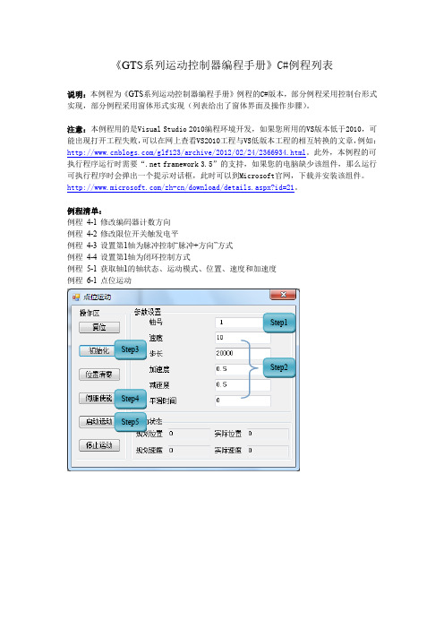
《GTS系列运动控制器编程手册》C#例程列表说明:本例程为《GTS系列运动控制器编程手册》例程的C#版本,部分例程采用控制台形式实现,部分例程采用窗体形式实现(列表给出了窗体界面及操作步骤)。
注意:本例程用的是Visual Studio 2010编程环境开发,如果您所用的VS版本低于2010,可能出现打开工程失败,可以在网上查看VS2010工程与VS低版本工程的相互转换的文章,例如:/glf123/archive/2012/02/24/2366934.html。
此外,本例程的可执行程序运行时需要“.net framework 3.5”的支持,如果您的电脑缺少该组件,那么运行可执行程序时会弹出一个提示对话框,此时可以到Microsoft官网,下载并安装该组件。
/zh-cn/download/details.aspx?id=21。
例程清单:例程4-1 修改编码器计数方向例程4-2 修改限位开关触发电平例程4-3 设置第1轴为脉冲控制“脉冲+方向”方式例程4-4 设置第1轴为闭环控制方式例程5-1 获取轴1的轴状态、运动模式、位置、速度和加速度例程6-1 点位运动Step1Step3Step2Step4Step5例程6-2 Jog运动例程6-3 PT静态FIFO Step1 Step2Step3Step4Step5Step1 Step2Step3Step4Step5例程6-4 PT动态FIFO例程6-5 电子齿轮跟随Step1Step2Step3Step4Step1 Step2 Step3例程6-7 Follow单FIFO模式Step1Step2Step3Step4例程6-8 Follow双FIFO切换Step1Step1Step2Step3例程6-9 建立坐标系例程6-10 直线插补例程例程6-11 圆弧插补例程例程6-12 插补FIFO管理例程6-13 前瞻预处理例程例程6-14 刀向跟随功能GT_BufMove() 例程6-15 刀向跟随功能GT_BufGear()例程 6-16 刀向跟随功能——实际工件加工 (例程6-9~16集成在一起)例程 6-17 PVT 描述方式 例程 6-18 Complete 描述方式 例程 6-19 Percent 描述方式 例程 6-20 Continuous 描述方式 例程 7-1 访问数字IO例程 7-2 读取8个轴编码器和辅助编码器位置值Step1Step2Step3Step1 Step2例程7-3 访问DAC例程7-4 访问ADCStep1Step4Step5Step2Step3Step1Step2例程 8-2 Home 回原点例程 8-3 Home+Index 回原点Step1Step2Step3Step2Step4 Step5 Step6Step1Step2Step3Step4Step5例程8-4 探针捕获例程8-5 HSIO捕获用法示例例程9-1 软限位使用例程10-1 运动程序单线程累加求和例程10-2 运动程序多线程累加求和例程11-1 读取运动控制器版本号例程11-2 电机到位检测功能例程11-3 自动回原点例程11-4 位置比较输出指令详细的用法Step1 Step2Step3Step4 Step5。
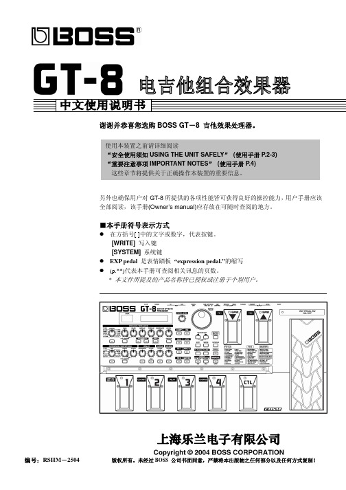
BOSS GT-8中文说明书
z 请勿在如下场所使用或放置本器材: 温差剧烈的场所(如阳光直射的车厢, 发热的管线附近,或是发热器材的上) 潮湿的环境(如浴室,洗手间,湿地板) 暴露在雨中的环境。 多尘的环境 剧烈振动的环境
z 请避免损伤电源线。请勿将它过度弯折,踩 踏或压上重物,…等。损伤的电源线可能会 导致触电或走火。电源线损坏后,请不要再 继续使用。
z 不管是搭配扩大机,耳机或喇叭来使用本器 材,都有可能发出足以伤害听觉的大音量。 请勿长时间在高音量,或足以引起不适的音 量下操作。如果发觉听力受损或耳鸣时,请 立即停止使用本器材,并向耳科医师求诊。
z 在国外使用本机时,请洽询最近的 Roland 服务中心,或 Roland 授权代理商 (详列于”Information”)。
z 请将本机与 AC 电源变压器置于通风良好 的地方。
z 将插头插入或拔离插座时,一定要握住 AC 电源变压器的插头部分。
z 应该定期将电源插头拔除,用干净的软布擦 拭插头上的灰尘,并用叉状物清除插头凹槽 部位堆积的灰尘。在长期不使用本设备的情 况下,要将电源线拔除防止灰尘堆积。电源 插头和插座之间聚集的灰尘可能造成不良 绝缘,导致火灾发生。
32
混响(REVERB)
33
压缩(COMP)
33
哇音(WAH)
34
FX-1/ FX-2
34
ACS(Advanced Compressor 高级压缩器)
35
LM(Limiter 限幅器)
35
TW(Touch Wah 触控哇音)
GTS系列运动控制器用户手册

2.3.3 步骤 3:建立主机和运动控制器的通讯 .................................................................7
2.3.4 步骤 4:连接电机和驱动器......................................................................................7
固高科技(深圳)有限公司
地 址:深圳市高新技术产业园南区深港产学研基地西座 二层 W211 室
电 话:0755-26970823 26970817 26970824 传 真:0755-26970846 电子邮件:support@ 网 址:
2.2 GTS 运动控制器的外形结构.................................................................................................5
2.3 安装步骤..................................................................................................................................6
限位信号输入 原点信号输入 驱动报警信号输入 驱动使能信号输出 驱动复位信号输出 通用数字信号输入 通用数字信号输出 点位运动
GTS 系列运动控制器 .................................................................................................................17
八工位运输小车PLC控制说明书

号编与配分的点 O/I
3.3
6
。示所 4-3 图如。图程流制控下以出绘以可�图制控气电及求要制控据根
图程流制控制绘
5.3
。示所 3-3 图如
�计设图线接统系行进以可�布分口端出输入输的 622UPC 和表配分 O/I 上以据根
6.3 5.3 4.3 3.3 2.3 1.3
CLP 章�第
2.2 1.2
2 ................................................................................................... 择选式方制控 2 ................................................................................................................. 明说择选案方体总 2 ........................................................................................................... 计设案方体总统系 1 ........................................................................................................................................... 言引
录附
71 ............................................................................................................................................................ 辞谢 61 ................................................................................................................................................. 结总计设 51 ............................................................................................................................................................ 论结 9 .......................................................................................................................... 制编序程制控 6 ..................................................................................................................... 图程流制控制绘 6 ................................................................................................... 图气电统系用应 CLP 作制 5 ............................................................................................................. 号编与配分的点 O/I 4 ................................................................................. 型类 CLP 择选�量数号信 O/I 定确 3 ...............................................................................................路电主计设�析分求要制控 3 .............................................................................................................计设统系制控
8-GTS-操作指南5

8-GTS-操作指南5GTS操作指南5 -熟悉生成三维网格-GT S 操作指南 559GTS 操作指南 5-熟悉生成三维网格-MIDAS/GTS 提供对于二维及三维模型自动便利地生成网格的方法,同时在各过程里也提供能便利生成质量更高的映射网格功能。
为了生成及管理三维网格,我们利用程序里提供的多样化功能中使用频率较高的功能生成简单的三维网格。
生成的网格以网格组(Mesh Set )为单位进行整理。
GTS 操作指南 5 –完成后的网格形状G ETTING S TARTED60 打开GTS 文件运行GTS 程序后打开模型文件。
1. 运行GTS 。
2. 在主菜单里选择File > Open…。
3. 打开‘操作指南GTS 5_Start.gtb’文件。
4. 在工作目录树里展开Geometry > Solid 。
共19个Solid 。
5.Displayed 选择所有的Solid 。
6. 在不进行任何选择的状态下在模型窗口的空白处点击右键调出关联菜单。
7. 选择Display Mode > Wireframe 。
8. 点击窗口右侧动态视图工具条下端的Toggle Face Iso-Lines 。
9. 在不进行任何选择的状态下在模型窗口的空白处点击右键调出关联菜单。
10.Toggle Grid 。
11. 在不进行任何选择的状态下在模型窗口的空白处点击右键调出关联菜单。
12. 选择Turn off All Triads 。
13. 在工作目录树里点击Datum 右键调出关联菜单。
14. 选择Hide All 。
上述打开的模型中共由19个实体构成。
由于是模拟贯通岩层的隧道,所以为了定义施工阶段按照施工阶段分割了实体。
Grid, 坐标轴, Datum 等都隐藏起来。
Displayed 的快捷键是Ctrl+A .GT S 操作指南 561GTS 操作指南 5 - 1GTS 操作指南 5 - 2G ETTING S TARTED62 线网格尺寸控制(Edge Size Control )与前面介绍的生成二维网格的方法比较类似,为了对重要的部分得到更精确的分析结果在线上事先指定网格大小。
XC608系列运动控制器用户手册V2.1

态。
●手动操作:可实现高、低速手动、点动、回坐标零、回机械零等操作。
●程序管理:可对当前加工程序进行修改、保存。
●自动加工:可实现单段/连续、空运行、暂停等功能。
2. 系统组成 数控系统主要由以下几部控制芯片(信号输出为:5V TTL)
输入/输出(30 路光电隔离 24V 输入,16 路光电隔离 24V 输出)
控制轴数:
3 轴(X,Y,Z)
联动轴数:
直线 3 轴(X,Y,Z),圆弧 2 轴(X,Y)
电子齿轮: 分子(n):1-65535,分母(m):1-65535
系统主要功能: 自动、手动、程序编辑、系统参数、自检、设置等。
4. 外观及面板 控制器外观:见首页
外形尺寸:205*150*45mm
嵌入孔尺寸:193*139mm
2. 相对湿度应控制在 0-85%。 3. 在高温、高湿、腐蚀性气体的环境下工作时,必须采取特殊的防护措施。 4. 防止灰尘、粉尘、金属粉尘等杂物进入控制系统。 5. 应防护好控制系统的液晶屏幕(易碎品):使其远离尖锐物体;防止空中的物体撞到屏幕
上;当屏幕有灰尘需要清洁时,应用柔软的纸巾或棉布轻轻擦除。
用户手册
XC608 系列运动控制器
(XC6081、XC6082、XC6083)
V2.0
XCMCU Corporation 1
一、 安全须知........................目...录..................................... 3 二、 概述.................................................................... 4
其它事项:
midas gts操作指南1

开始文件 结果文件
GTS操作指南 1.gtb 无
打开GTS文件
运行GTS程序后打开简单的模型文件。
1. 运行GTS。 2. 在主菜单里选择File > Open…后打开‘GTS操作指南 1.gtb’。
GTS操作指南 1 - 1 1
GETTING STARTED
设定操作环境
设定GTS的操作环境。一旦设定了操作环境就会保存到Registry中,所以即使退出程 序重新运行也会保留已设定的操作环境。
Unselect Mode Unselect All
如果激活Unselect Mode,那么就不能添加选择只能取消 选择。如果选择若干个对象时转换成Unselect Mode的话 那么就象选择时一样会取消选择已选中的对象。 点击此按钮的话会取消所有的选择。
7
GETTING STARTED
Solid Face
GCS和WCS, 基准(Datum)和工作平面(Work Plane)
在GTS里使用的坐标体系有GCS, WCS, User Defined Coordinate。在上述坐标系里程
序经常使用的是GCS和WCS,用户可以任意生成并使用User Defined Coordinate。
现在模型窗口的背景颜色 GCS是固定的坐标轴,在画面上用红色(x轴), 绿色(y轴), 蓝色(z轴)的方向箭来表示。
9
GETTING STARTED
35. 在工作目录树里点击‘Rectangle – Face’的鼠标右键。 36. 选择Show。 37. 在画面上确认是否出现Face。 38. 在工作目录树的Surface里确认‘Rectangle – Face’的图片显示是否由
。
转变为
RMC100系列双轴、四轴、六轴、八轴轨迹轨道控制器说明书

RMC100 SeriesTwo, Four, Six, and Eight AxisServo Motion ControllersThe RMC100 series brings thebenefits of modular, high-performance motion control to a wide range of industrial applications.Communication options —ranging from high-speed fieldbuses to discrete I/O —make these controllers an excellent choice for large and small systems. Transducer types can be combined to control any hydraulic, electric, and pneumatic system. Powerful control modes —including position/pressure control,synchronized moves, gearing, splines, and teach mode —provide optimum control for your motion applications. Refer to other RMC data sheets or the RMCWin online help for more information. Download RMCWin from Delta’s web site at . Applications ∙ Presses∙ Injection/RIM/blow molding ∙ Packaging equipment ∙ Indexing/transfer lines∙ Edgers/headrigs/veneer lathes ∙ Pinch rollers/winders/wrappers ∙ Casting/forging ∙ Palletizers/stackers∙ Flying cutoff/curve sawing ∙ Cyclic testing∙ Robotics/animatronics ∙ Pneumatic press rolls ∙ Tube bending/formingFeatures∙ Two to eight axes of position or speed control∙ Isolated power input, drive outputs, discrete and analog I/O, and communications∙ RS-232 port for RMCWin and the RMCCOM ActiveX Control ∙ Full PID with velocity and acceleration feed-forwards∙ Motion and pressure profiles can be changed on-the-fly∙ 256K FLASH memory for field upgrades and parameter storage ∙ Trapezoidal, S-curve, and spline profiling ∙ Teach mode∙ Synchronization of 2-8 axes ∙ Electronic gearing∙ Compact DIN-rail mount package Communications ∙ PROFIBUS-DP ∙ Ethernet ∙ Modbus Plus∙ Discrete I/O – 20 inputs, 10 outputs ∙ Serial (RS-232/422/485) Position Transducer Interfaces ∙ Magnetostrictive Transducers – Start/Stop, PWM, and SSI ∙ Analog Transducers – 16 bit ∙ Quadrature Encoders∙ Absolute encoders and resolvers with Synchronous Serial Interface Drive Outputs∙ All feedback interfaces are available with analog ±10 Volt outputs ∙ Quadrature and SSI feedback interfaces are available with stepper outputRMCWin SoftwareDelta’s powerful RMCWin fo rWindows 95/98/NT/2000/XP makes setup, tuning, and troubleshootingmotion systems easier than ever.∙ Provides a graphic display of the latest motion profile, position and drive information∙ Includes context-sensitive help and complete user manual online∙ Calculates scale, offset, and velocity feed forwards∙ Allows user to activate motion profiles and change control parameters from a PC∙ Displays parameter and status information for all axesEvent Control∙ Repeatable execution of motion commands each loop (1 or 2ms) ∙ Provides easy, spreadsheet-style programming∙ Responds to time delays, status bit conditions, position, or inputs ∙ Includes 256 event steps RMCCOM ActiveX Control Control the RMC from your Visual Basic, Visual C++, Java, and VBA (e.g. Excel) programs.Pressure/Force Control Option ∙ Control pressure or differential force at 12- or 16-bit resolutionPosition Axis Parameters P ressure/Force Axis Parameters Setup Parameters S etup ParametersConfigurationScaleOffsetExtend LimitRetract LimitProportional GainIntegral GainDifferential Gain Extend Vel. Feed Forward Retract Vel. Feed Forward Extend Accel. Feed Fwd Retract Accel. Feed FwdDead Band EliminatorIn PositionFollowing Error Automatic Stop Enable Controller operating configurationThese fields allow for position unitconversionMaximum position allowedMinimum position allowedProportional gain for PID loopIntegral gain for PID loopDifferential gain for PID loopOpen loop compensation termsproportional to target velocityOpen loop compensation termsproportional to target accelerationValve dead band compensationWindow for in-position indicationAllowable position errorEnable for stop on errorsConfigurationScale AOffset AScale BOffset BProportional GainIntegral GainDifferential GainExtend Feed ForwardRetract Feed ForwardIntegrator PreloadDrive Transfer PercentAt Pressure WindowPressure WindowAutomatic Stop EnableController operating configurationThese fields allow for unitconversion for both pressure anddifferential force transducers.Proportional gain for PID loopIntegral gain for PID loopDifferential gain for PID loopOpen loop compensation termsproportional to pressure changeEnable tuning of bumpless transferfrom position to pressure controlWindow for at-pressure indicationAllowable pressure/force errorEnable for stop on errorsDynamic Control Parameters D ynamic Control ParametersMode AccelerationDecelerationSpeed Command ValueCommand Select from these features:Graph disableS-curve rampsSynchronizationElectronic GearingQuick modeMonitor Pressure modeIntegrator modes(avoid windup and overshoot)Acceleration rate, distance, or timeDeceleration rate, distance, or timeMaximum speed during a moveDestination positionCommand to be executed(refer to online help for complete listof commands)ModePressure Set APressure Set BRamp TimeCommand ValueCommandSelect from these features:Curved and linear rampsAuto-calculated ramp slopeIntegrator modes(avoid windup and overshoot)Pressure control entry thresholdPressure control exit thresholdTime to ramp between pressuresDesired pressureCommand to be executed(refer to online help for complete listof commands)Status Information S tatus InformationCommand Position Target PositionActual Position Transducer CountsStatus WordDriveActual SpeedNull DriveStepLink Value Requested position within limitsCalculated desired position of axisMeasured position based on currentTransducer Counts that have beenScaled and OffsetRaw transducer countsAxis errors and statusDrive output in millivoltsCalculated speedCurrent null drive in millivoltsLast step executedValue at which next step executesCommand Pressure/ForceTarget Pressure/ForceActual Pressure/ForceTransducer Counts ATransducer Counts BActual Force AActual Force BStatus WordDriveRequested pressure/forceCalculated desired pressure/forceCurrently measured pressure/forceRaw value read from analogtransducersValues of each force component in adifferential force applicationAxis errors and statusDrive output in millivoltsFor detailed explanations of these parameters and RMC functionality, refer to RMCWin’s online help. Download RMCWin from Delta’s web site at .RMC100 Series SpecificationsMotion Control Control loop timeMaximum speed 1 or 2 ms depending on module configuration 65,535 user-defined position units per secondRS-232 Port Interface with Delta's RMCWinand RMCCOM ActiveX Control.ConnectorCable Requires a PC with Windows 95/98/Me/NT/2000/XP. DB-9 MaleNull modemRJ-11 LCD Terminal Jack Interface with Delta’s optionalfour-line 20-character LCDdisplay with keypad Allows viewing status information, changing parameters, and issuing commandsDiscrete I/O IsolationLogic PolarityInputsInput voltage thresholdInput current thresholdOutputs 2500 VAC optically isolatedTrue High2; independent (sink or source)6 mA max at 5 V; 10 mA max at 24 V26.4 VDC maximum2.75 VDC typical, 3 VDC Max2.7 mA typical,3.2mA maximum2; independent (sink or source)Solid State Relay, 50 Ω maximum on resistance, 30 V and 100 mA maximum, Tpd max of 1.5 msPower VoltageCurrent – 2 axes (3 slots)4 axes (4 slots)6 axes (5 slots)8 axes (6 slots)DC-DC converter isolation +24 VDC ±20%Typical 290 mA @ 24 VDC, max 375 mA Typical 385 mA @ 24 VDC, max 500 mA Typical 485 mA @ 24 VDC, max 625 mA Typical 585 mA @ 24 VDC, max 750 mA 500 VAC, 700 VDC, input to controllerMechanical MountingDimensions – 2 axes (3 slots)8 axes (6 slots)Weight – 2 axes (3 slots)8 axes (6 slots) Symmetrical DIN 3 or panel-mount4.12 x5.95 x 4.75 in (10.5 x 15.0 x 12.1 cm) (WxHxD) 7.12 x 5.95 x 4.75 in (18.1 x 15.0 x 12.1 cm) (WxHxD)2.0 lb (0.9 kg) max3.0 lb (1.4 kg) maxEnvironment Operating temperatureStorage temperatureAgency compliance +32 to +140︒F (0 to +60︒C) -40 to +185︒F (-40 to +85︒C) CE, UL, CULWiring Information for the RMC100RS-232:Pin Function2 Receive3 Transmit5 CommonPower:Pin Function+24V +24 Volt Input24 Cmn 24 Volt CommonCase Controller Chassis Ground (shield) Discrete I/O:Pin Function+ In 0 + Input 0- In 0 - Input 0+ In 1 + Input 1- In 1 - Input 1+ Out 0 + Output 0- Out 0 - Output 0+ Out 1 + Output 1- Out 1 - Output 1RMC100 Series Part NumbersNot all combinations of modules are possible. See individual data sheets for details on modules and options. This information plus an easy-to-use Price List program are available on our web site at .Accessories Part Number DescriptionLCD420 LCD display and keypad VC2100Voltage-to-current converterSSn-PEn-BGnFamily of Servo System and Position/Pressure SimulatorsCompany ProfileDelta Computer Systems, Inc. manufactures motion controllers, color sensors/sorters, and other industrial controls providing high-performance automation solutions to a wide range of industries.Printed in USA 02/09/10 RMC100 Series.docVC2100 LCD420RMC100-M1-PROFIRMC100-M1-PROFIRMC100 Series CPU Pressure/Force Control Option(0=disabled, 1=enabled)(Multiple options possible)Magnetostrictive Displacement Transducer (MDT) module (Start/Stop and PWM) (designate -M n , n = 1-4 modules; 2 axes per module)Quadrature modules(designate -Q n , n = 1-4 modules; Analog output, 2 axes per module) (designate -QST n , n = 1-4 modules; Stepper output, 2 axes per module) Analog modules(designate -H n , n = 1-4 modules; four 16-bit inputs / 2 axes per module) (designate -G n , n = 1-4 modules; two 16-bit inputs / 2 axes per module) (designate -A n , n = 1-2 modules; four 12-bit inputs only per module) Sensor DI/O module (designate -D1)Synchronous Serial Interface (SSI) modules (MDT, absolute encoder, resolver) (designate -S n , n = 1-4 modules; Analog output, 2 axes per module) (designate -SST n , n = 1-4 modules; Stepper output, 2 axes per module) Communication(designate -PROFI , -DI/O , -MB+, -ENET , -SERIAL ; others in development)。
GTS 激光控制说明书
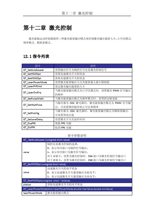
第十二章激光控制激光振镜运动控制器提供三种激光能量输出模式来控制激光输出能量大小:占空比模式,频率模式,模拟量模式。
12.1指令列表无效FPK信号12.2 重点说明12.2.1 激光能量输出方式激光振镜运动控制器可提供四种激光能量输出模式,除模拟量输出模式外,首先需要将对应的信号输出口从轴控信号输出切换到激光信号输出,即调用函数GT_SetAxisAsLaser(1),然后再分别根据如下模式操作:●占空比输出模式1:通过设置频率和占空比调节激光器能量。
使用时调用函数GT_LaserPowerMode()设置为占空比输出模式,调用函数GT_LaserOutFrq()设置PWM信号的输出频率,调用函数GT_LaserPrfCmd()设置PWM信号的输出占空比,调用函数GT_SetHSIOOpt()启动输出。
●频率输出模式:通过设置频率和脉宽调节激光器能量。
使用时调用函数GT_LaserPowerMode设置为频率输出模式,调用函数GT_LaserPrfCmd()设置频率输出值,调用函数GT_SetHSIOOpt()启动输出。
●模拟量输出模式:通过设置输出电压调节激光器能量。
使用时调用函数GT_LaserPowerMode()设置为DA 输出模式,调用函数GT_LaserPrfCmd()设置DA输出值,调用函数GT_SetHSIOOpt() 启动输出。
●占空比输出模式2:通过设置频率和占空比调节激光器能量,激光开关信号为恒高信号。
使用时调用函数GT_LaserPowerMode()设置为占空比输出模式2,调用函数GT_LaserOutFrq()设置占空比信号输出频率,调用函数GT_LaserPrfCmd()设置占空比信号输出占空比,立即模式调用函数GT_SetHSIOOpt()启动输出。
当激光能量输出模式为占空比输出模式或者频率输出模式时,其输出的PWM信号占空当激光能量输出模式为模拟量输出时,范围为0V~10V。
- 1、下载文档前请自行甄别文档内容的完整性,平台不提供额外的编辑、内容补充、找答案等附加服务。
- 2、"仅部分预览"的文档,不可在线预览部分如存在完整性等问题,可反馈申请退款(可完整预览的文档不适用该条件!)。
- 3、如文档侵犯您的权益,请联系客服反馈,我们会尽快为您处理(人工客服工作时间:9:00-18:30)。
相关文件
关于GTS系列运动控制器的编程,请参见随产品配套的《GTS系列运动控制器编程 手册》。
© 2013 固高科技 版权所有
Hale Waihona Puke 文档版本版本号 1.0 1.1 1.2 2.0 修订日期 2009 年 09 月 15 日 2010 年 05 月 17 日 2011 年 09 月 19 日 2013 年 04 月 08 日
轴信号接口 .................................................................................................................................. 15 通用 IO 号、Home 信号和 Limit 信号接口 ............................................................................... 16 辅助编码器接口 .......................................................................................................................... 20 HSIO 接口 ........................................................................................................................................ 21
运动控制器 用户手册
GTS 系列 8 轴
V2.0
2013.04
© 2013 固高科技 版权所有
版权申明
固高科技有限公司 保留所有权力
固高科技有限公司(以下简称固高科技)保留在不事先通知的情况下,修改本手册 中的产品和产品规格等文件的权力。 固高科技不承担由于使用本手册或本产品不当,所造成直接的、间接的、特殊的、 附带的或相应产生的损失或责任。 固高科技具有本产品及其软件的专利权、版权和其它知识产权。未经授权,不得直 接或者间接地复制、制造、加工、使用本产品及其相关部分。
硬件连接 .............................................................................................................................................. 15 端子板接口定义 .................................................................................................................................. 15
© 2013 固高科技 版权所有
目 录
第1章 1.1 1.2 1.2.1 1.2.2 1.2.3 1.2.4 1.2.5 1.3 第2章 2.1 2.2 2.3 2.4 2.4.1 2.4.2 2.4.3 2.4.4 2.4.5 2.4.6 第3章 3.1 3.1.1 3.1.2 3.1.3 3.1.4 3.2 3.2.1 3.2.2 第4章 4.1 4.2 4.3 4.3.1 4.3.2 4.3.3 4.3.4 4.3.5 概述 ........................................................................................................................................................ 1 简介 ........................................................................................................................................................ 1 型号说明 ................................................................................................................................................ 1 GTS 运动控制器 ................................................................................................................................ 1 8 轴端子板 ......................................................................................................................................... 2 GTS-800-PV(G)-PCI .......................................................................................................................... 2
运动中的机器有危险!使用者有责任在机器中设计有效的出错处理和安全保护机制, 固高科技没有义务或责任对由此造成的附带的或相应产生的损失负责。
联系我们
固高科技(深圳)有限公司
地 电 传 网 址:深圳市高新技术产业园南区深港产学研 基地西座二楼 W211 室 话:0755-26970817 真:0755-26970821 址: 26737236 26970824 电 传 网
步骤 1:将运动控制器插入计算机 ............................................................................................. 7 步骤 2:安装运动控制器驱动程序 ............................................................................................. 7 步骤 3:建立主机和运动控制器的通讯 ................................................................................... 11 步骤 4:连接电机和驱动器 ....................................................................................................... 12 步骤 5:连接运动控制器和端子板 ........................................................................................... 13 步骤 6:连接驱动器、系统输入/输出和端子板 ...................................................................... 14
转接板 ............................................................................................................................................ 3 8 轴端子板 ......................................................................................................................................... 4
