卡特CAT3516B气门间隙及喷油器调整-2
CAT 3516B-HD型柴油机操作保养规程

1 操作人员1)柴油机的操作人员应接受该项目的专门培训、并经合格鉴定后方具备操作的资格;2)负责培训的指导教师应具备操作资格,并负责受训人员的操作技能鉴定;3)受训人员应在指导教师的监督下至少接受2小时的实操训练,经指导教师鉴定完全合格后方可使用柴油机。
在最初的2个工作时内使用应在指导教师的监督下进行,其后经指导教师鉴定完全合格后可进行独立操作。
4)所有现场培训的记录应保存。
2 操作前检查:1) 检查柴油机防护装置及保护装置是否处于正常状态。
2)检查柴油机周围是否有泄漏的液体(冷却液、润滑油、燃油等)及固定(螺栓、线缆连接等)是否有松动,如有,找出并排除。
3)检查机油、冷却液、燃油、气马达油杯、油马达油杯等液位是否正常,空气滤器指示器是否在正常范围。
4)排放燃油箱水及沉淀物。
5)打开冷却系统、启动系统、燃油系统及燃油冷却器各相关阀门,检查冷却水泵是否运转正常,缸套水散热器风机是否处于自动启动状态,温控阀是否处于可用状态。
6)冬季各停用柴油机水套加热器应打开,运转前关闭水套加热器。
3 运行:1) 将柴油机控制开关打到“人工启动”位置启动柴油机。
2)关闭启动空气供给阀门。
3)操作柴油机在怠速下运转2-3分钟,在提高转速到额定前,使缸套水温开始上升。
4)在预热升温期间,检查所有仪表读数是否正常,检查冷却水泵进排水压力是否正常。
5)再次检查柴油机周围是否有液体泄漏及固定松动。
6)预热升温后柴油机自动增加转速到额定值,空转运转。
7)闭合主断路器以便加载负荷。
如使用自动功能,将柴油机控制开关达到自动位置,在总功率达到额定85﹪时自动投入运转。
4 运行中的检查:运转过程中,将CLEAR/MODE开关拨向MODE,当液晶屏显示0时,为正常运转状态,液晶屏显示转速,同时可通过拨动SCROLL来查看运转时间; 如果检查各仪表确切参数, 将CLEAR/MODE开关拨向MODE,当液晶屏显示1时, 通过拨动SCROLL开关, 当液晶屏显示GA-1时,可读出第1块表的读数,同理可顺序读出其它各表读数.当将CLEAR/MODE开关拨向MODE,当液晶屏显示2时,为故障诊断模式,查看其代码并排除故障。
卡特彼勒3516C船用发动机常见问题及处置办法

卡特彼勒3516C船用发动机常见问题及处置办法谢威【摘要】卡特彼勒3516C船用发动机是一款特性强劲、稳定性好的动力系统。
但是,在长期使用中,依然会碰到一些常见问题。
本文就卡特彼勒3516C船用发动机常见问题,并提供相关处置办法。
【关键词】船用发动机|常见问题|处置办法卡特彼勒3516C船用发动机拥有出色的性能稳定性,主要适用于船只应用。
该发动机轴径做到16英尺,转速比为1800转/min,可以提供达到1765大马力的动力输出。
不论是在商业服务、航运业或是国防舰船应用中,卡特彼勒3516C发动机都能够胜任重担。
一、卡特彼勒3516C船用发动机介绍卡特彼勒3516C船用发动机配置了前沿的强制润滑系统,保证发动机各部件得到很好的润滑和制冷,提升发动机的寿命和稳定性。
这一系统使用了高效率的过滤器和冷却系统,可以在各类条件下维持发动机的正常使用。
为了满足危险区使用需求,卡特彼勒3516C船用发动机具有防爆型作用。
为应对高温环境下的运转要求,卡特彼勒3516C船用发动机的曲轴箱通风选用铝合金型材,具有较好的导热性能。
而散热器则采用了不锈钢板材,可以有效地降低发动机环境温度,维持发动机的正常运转。
最终,卡特彼勒3516C船用发动机还配有智能监控系统,可以实时监控系统发动机的运行状态。
这一自动控制系统检测每个传感器数据信息,确认常见故障,并提供相关保障措施。
二、卡特彼勒3516C船用发动机常见问题(一)燃油系统故障燃油系统是船用发动机中一个关键的部件,常见的故障包括:1.供油管路出现裂缝或者被异物堵塞,导致燃油供应不足,影响发动机正常的燃烧过程。
裂缝会导致燃油泄漏,使得燃油无法到达发动机燃烧室,从而降低了燃烧效率;而异物堵塞则会阻碍燃油的流动,导致燃油供应不足,使发动机无法正常运转。
2.如果油箱内的燃油量不足,就会导致发动机无法正常运转,甚至造成停机[1]。
3.低压力会导致喷油不充分,影响燃烧效率。
当燃油供应系统的压力不足时,喷油器无法将燃油以足够的压力喷入燃烧室,导致燃烧不完全,降低了发动机的性能和燃烧效率。
柴油机气门间隙的两次调整法

柴油机气门间隙的两次调整法柴油机气门间隙两次调整法,调整速度快,应用较多。
实践中,又有“一分为二”法、“右排、左进、压缩全调”法以及“双-排-不-进”法等。
利用“坐标-辐线图”经变换可以得出以上几种方法。
1.“一分为二”法四冲程柴油机,从第Ⅰ缸活塞处于压缩行程上止点开始调整气门间隙,若为偶数缸,点火顺序为1-5-3-6-2-4的6缸机,除第Ⅰ缸的进排气门均可调外,余下缸的点火顺序可一分为二,即5-3-6-2-4,被分隔线划中的第Ⅵ缸的进排气门均不能调整,分隔线左侧缸的排气门和右侧排气门全可调整。
调整完后,将曲轴转一周,在调整第一次没有调整的气门间隙。
若为奇数缸,点火顺序为1-2-4-5-3的5缸机,除第Ⅰ缸的进排气门均可调外,用分隔线将余下缸(2-4-5-3)一分为二,分隔线的左侧的排气门和右侧的进气门全可调整。
调整完后将曲轴转一周,在调其余的气门。
2.“右排、右进、压缩全调”法将某缸(如A缸)置于压缩上止点时,按做功顺序排列,并使处于中间做功的某缸(如B缸)于A缸上下对正,并使A、B左右两列气缸数相等。
压缩全调是指A缸处于压缩上止点时,进排气门均可调;左进是指A缸处于压缩上止点时,排列在A、B左侧的进门可调;右排是指在同样情况下,排在A、B右侧的各缸的排气门可调;B缸此时处于排气上止点处,进排气门均不可调。
3.“双-排-不-进”法根据缸数和气缸做功顺序,将各缸号写在“双-排-不-进”4个字下方。
对于缸数小于或等于8缸的柴油机,按做功顺序“双”“不”2个字的下方各写1个缸号,而在“排”“进”2个字的下方各写1、2、3个缸号。
对于10刚柴油机,在“双”“不”2个字下方各写3个缸号。
而在“排”、“进”2个字下方各写2个缸号。
对于12缸柴油机,在“双-排-不-进”4个字下方各写3个缸号。
对于10、12缸柴油机,在“双”字下方的3个缸号应是按做功顺序的第1、2个缸号和最后1个缸号。
当写在“双”字下方的缸号处于压缩上止点时,此缸的进排气门均可调,与此同时,写在“排”字下方缸号排气门可调,写在“进”字下方缸号的进气门可调,写在“不”字下方缸号的进气门均不可调。
CAT3516B柴油机振动故障及排除方法
CAT3516B柴油机振动故障及排除方法发布时间:2021-05-20T07:45:37.093Z 来源:《中国科技人才》2021年第8期作者:靳从升1 袁振2 郭晓亮3 秦杰荣4[导读] 钻井平台柴油机一般与匹配的发电机组成一套柴油发电机组,为钻井平台提供用电保障,是钻井平台能否正常生产的先决条件,素有钻井平台的“心脏”之称,也是钻井平台电力的唯一来源。
中国石油集团海洋工程有限公司天津市滨海新区 300451【摘要】:钻井平台配备的卡特3516B柴油机是一款具有深盆燃烧室的电喷柴油机,具有精准的调速系统、优化的涡轮增压器匹配和进排气系统。
CAT3516B通过利用电喷的优点提高了燃油经济性和扭矩,是多数钻井平台首选配备的柴油机之一,本文主要以CAT3516B为例介绍柴油机振动故障原因及排除方法。
【关键词】:CAT3516B 柴油机振动【引言】:钻井平台柴油机一般与匹配的发电机组成一套柴油发电机组,为钻井平台提供用电保障,是钻井平台能否正常生产的先决条件,素有钻井平台的“心脏”之称,也是钻井平台电力的唯一来源。
柴油机运转是否正常,直接影响着发电机的工作状态和稳定性,因此当柴油机出现振动故障是否能及时解决,是确保柴油机不“带病”运转、延长柴油机和发电机使用寿命的重要影响因素之一。
1、CAT3516B柴油机振动的主要原因有1.1曲轴减振器异常曲轴减振器的作用是限制曲轴的扭振,CAT3516B柴油机采用粘滞减振器,配有环形重块,重块至于充满液体的环形壳体内随曲轴一起转动。
如果曲轴减振器出现凹陷、裂纹或液体渗漏等故障,则会增加柴油机的扭振,损坏曲轴和柴油机其它零部件。
同时曲轴减振器温度过高也会引起扭振过大,一般柴油机运转时减振器的温度在100摄氏度以下。
如果曲轴减振器出现凹陷或者裂纹,则需要更换曲轴减振器;若曲轴减振器出现泄漏,则需要确定泄漏液体的类型,如是机油则需要更换曲轴油封,如果是透明,粘滞和光滑的液体则是减振器中的硅树脂,如无法修复渗漏点,也需要更换减振器。
卡特彼勒3512B操作规程整理版
3512B柴油发电机组操作规程1 范围本标准规定了石油钻机用3512B柴油发电机组的操作及维护保养规程。
本标准适用于石油钻机用3512B柴油发电机组的操作与维护保养,其他型号的柴油机发电机组的操作保养亦可参照本标准执行。
2 主要参数3512B柴油发电机组如下:柴油机型号: 3512B柴油机额定转速: 1500rpm柴油机怠速转速: 650rpm柴油机汽缸数及排列方式: 12缸 60°夹角V型柴油机汽缸直径: 170mm柴油机活塞行程: 215mm柴油机压缩比: 15.5:1柴油机进气方式:涡轮增压柴油机单一活塞排量: 4.9L柴油机活塞总排量: 58.5L柴油机转向(从飞轮末端看):逆时针柴油机使用燃油: -10#柴油(环境温度低于-5℃时须使用更低牌号的柴油)柴油机燃油喷油方式:电子喷油器柴油机启动方式:气动马达启动发电机型号: SR4发电机功率: 1200KW/1714KVA发电机频率: 50HZ发电机电压: 600V发电机最大电流: 1828A励磁电流: 7.5A3 操作使用3.1 柴油发电机组安装3.1.1 整个发电房底座应全长支撑,放在结实水平的基础或地面上,基础的水平度不大于3mm,基础承压力大于7MPa。
3.1.2 排气管系安装时要单独支撑、固定牢靠,排气管系统要有防水进入设施。
在安装期间要防止焊渣或其它杂物进入柴油机。
3.1.3 在安装燃油管线时,在管线接到柴油机之前,要从管线中清除所有的杂质。
3.1.4 连接输出电缆和控制线路;将发电房、SCR(VFD)房等根据实际情况牢固的接地。
SCR(VFD)房要用1.5米长的铜皮铁钎砸入地内,并浇盐水,保证接地电阻小于1Ω。
3.2 柴油发电机组启动3.2.1 启动前准备――确认已完成必要的每日维护和周期性维护;――确认柴油发电机组和他的控制系统处于正常状态,没有悬挂维修挂牌或警告牌;――确认所有护罩和护盖已安装到位,防护装置在正确的位置;――检查水温和油温,确保水套加热器(若装有)和/或润滑油加热器(若装有)工作工常,。
CAT3512B操作规程(2)
CAT3512B操作规程(2)中曼伊拉克项目CAT3512B柴油发电机组操作规程一、安装1、整个发电房底座应全长支撑,放在结实水平的基础或地面上,保持水平与平稳,发动机底座三个固定减震螺栓要固定牢靠。
2、为防止损坏发动机,排气管系应单独支撑、固定牢靠。
在安装期间要防止焊渣或其它杂物进入发动机。
所有排气管系统要防止水进入。
3、在安装燃油管线时,在管线接到发动机之前,应该从管线中清除所有的杂质。
4、连接好输出电缆和控制线路;将发电机外壳、SCR(VFD)房牢固接地。
二、启动1 、启动前准备(1)若发动机启动开关或控制件上挂有锁定警告牌时,千万不启动发动机或控制件。
启动发动机前应先与向此警告牌的人员进行咨询;(2)确保进行保养时拆下或打开的所有护罩和护盖已安装到位,防护装置必须在合适的位置。
修理损坏的或者安放丢失的防护装置;(3)确保水套加热器工作工常。
(4)启动和操作发动机时保持周围通风良好。
若在封闭区启动发动机,要把废气排放到外面;(5)确保转动部件的周围无杂物。
2、启动前巡回检查为了最大限度地延长工作寿命,启动柴油机前要进行彻底的检查。
诸如:润滑油、燃油和冷却剂是否泄漏、风扇皮带是否松动、以及废弃物的堆积之类项目。
(1)吸气系统a. 确保吸气管和空气滤清器在适当的位置;b. 确保所有管线夹子和接头安全、牢靠;c. 察看空气清洁器伺服指示器。
当黄色横隔膜进入红色区或者红色活塞在可见位置锁住时,应清洗空气清洁器。
(2)冷却系统a. 检查冷却系统是否有泄漏和接头松动现象;b. 检查冷却系统的软管夹扣是否有松动现象;c. 检查水泵是否有泄漏迹象;d. 检查风扇驱动皮带是否有裂纹、老化现象;e. 检查防冻液液面,必要时添加冷却剂。
(3)驱动设备a. 完成驱动设备需要的所有维护;b. 确保主电路断路器断开。
(4)电力系统检查电路的下列情况:a. 接头是否松动;b. 电线是否磨损;c. 检查交流发电机皮带是否有裂纹或者老化;d. 确保接地安全。
3512柴油发电机组使用操作规程
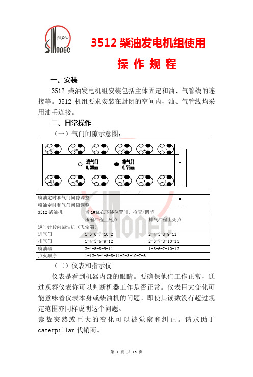
3512柴油发电机组使用操 作 规 程一、安装3512柴油发电机组安装包括主体固定和油、气管线的连接等。
3512机组要求安装在封闭的空间内,油、气管线均采用油壬连接。
二、日常操作(二)仪表和指示仪仪表是看到机器内部的眼睛。
要确保他们工作正常,通过观察仪表你可以判断机器工作是否正常。
仪表巨大变化可能意味着仪表本身或柴油机的问题。
即使其读数没有超过规定范围亦同样说明这个问题。
读数突然或巨大的变化可以被觉察和纠正。
请求助于caterpillar 代销商。
仪表读数限制信息板固定在仪表盘侧面,列出了在额定载荷和转速下柴油机最大限制。
1、机油:显示机油压力。
冷机启动后,机油压力增大,怠速暖机后机油压力会降低。
增加至全速后,机油压力将上高并保持稳定。
正常工作油压应在275~600kPa之间(在110℃使用SAE30W机油水箱水温正常时)。
怠速时应在186~344kPa。
若仪表读数在载荷稳定时不稳定:●摘下载荷●降低柴油机转速到怠速●检查油面2、油滤压差:显示机油滤子进油端和出油端两端的压力差。
当滤子堵塞时,两端的压力差将会升高。
油滤子最大压力差是105kPa。
3、机油温度:显示机油温度。
全载时机油最高温度为104℃。
机油温度油一个与机油接触的82℃的恒温器控制。
机油用于润滑轴承和内部所有运动部件,冷却活塞。
油冷器将热量从机油传递到水箱水中。
若水箱散热系统功能有误,机油不能足够冷却。
高于正常温度的机油表明润滑或冷却系统出现热故障,问题可能出在缸盖,缸套,活塞或曲轴轴承。
4、冷却水(1)水箱水温:显示柴油机水箱冷却水温度。
水温可能随载荷变化但不会超过沸水温度。
柴油机应当在正常范围内工作。
水箱温度应当在88~100℃之间。
有时在装配有膨胀水箱或热交换器的情况下水温可能达到112℃。
水箱进水口温度由系统内恒温器调节。
工作时必须配有恒温器。
若柴油机工作时水温较高,则:●卸掉载荷,降低转速。
●观察冷却系统有无泄露。
●确定柴油机需立即停车还是卸掉载荷后温度已经降低。
气门间隙调整方法和步骤

气门间隙两次调整法最简单的调整步骤周利顺【摘要】:正气门间隙两次调整法最简单的调整步骤: (1)摇转曲轴,使第一缸处于压缩上止点位置,借助于厚薄规测量,将所有缸(注意:即发动机的各个气缸)的进、排气门均调至规定间隙。
【关键词】:两次调整法气门间隙调整步骤多缸发动机压缩上止点厚薄规曲轴排气门简单摇转【正文快照】:气门间隙两次调整法最简单的调整步骤: (l)摇转曲轴,使第一缸处于压缩上止点位置,借助于厚薄规测量,将所有缸(注意:即发动机的各个气缸)的进、排气门均调至规定间隙。
(2)摇转曲轴360‘,用厚薄规检查除第一缸以外的其他缸各个气门的间隙。
若间隙减小或未变,则该气门已调整准确气门间隙调整——检查调整步骤首先大家要知道气门摇臂与气门的间隙(即气门间隙)之所以存在,是因为进排气门均安装在燃烧室的顶端,也是温度最高之处,为了留有膨胀的空间,因而必须存有空隙,至于间隙的大小,因厂家设计不同而不一致,通常在0.2~smarttags" />0.25毫米之间。
发动机气门摇臂与此气门之间经过长久的动作及磨耗,间隙会愈变愈大,所以才有气门脚间隙的调整。
然而并非所有汽车均需调整气门脚间隙,有些车辆气门间隙属于油压自动调整,就不需要调整气门间隙了。
(1)拆下气门室盖。
拆下气门室盖的固定螺丝,小心取下气门室盖,注意不要损坏气门室盖衬垫。
用抹布擦净气门及摇臂轴上的油污,以方便气门调整作业。
(2)找到一缸压缩上止点。
用摇手柄转动曲轴或撬动飞轮,使一缸处于压缩上止点位置。
从发动机前面看,曲轴皮带轮的正时凹坑与正时记号对准。
在部分大型车上飞轮壳的检视孔1-6缸刻线与飞轮壳正时记号对齐。
例如:东风EQ6100-1型发动机,飞轮1-6缸刻线应与飞轮壳的钢球对齐。
此时从气门处看:一缸的气门应都处开关闭的状态。
如果一缸的气门不全是关闭状态,说明一缸活塞在下止点位置,您应再转动曲轴360度,使一缸处于压缩上止点位置。
CAT 3512B柴油机操作保养规程(新)
.C A T3512B柴油机操作保养规程1 操作前的准备。
1.1 围绕发动机检查1.1.1 清除柴油机机体和周围空间的杂物,保持柴油机机体和机舱地板的清洁,以利于操作安全。
1.1.2 检查地脚螺栓、联轴器螺栓及外部各紧固螺栓的紧固情况。
1.1.3 检查飞轮外罩无异常,确保旋转零件周围无障碍物。
1.1.4 检查启动马达啮合齿轮位置是否正常。
1.2 空气系统检查1.2.1 检查启动气源,气瓶压力应在7~10kg/cm2之间。
1.2.2 检查紧急停机风门是否在正常位置。
1.2.3 检查空气滤网是否清洁。
1.2.4 确保所有卡箍和连接处牢固可靠。
1.3 冷却系统检查1.3.1 检查缸套水及中冷水膨胀水箱水位,不足时应加够,如柴油机经常运转,但水位明显降低,应查明原因。
1.3.2 检查缸套水加热器管线球阀是否打开。
1.3.3 检查冷却系统是否有渗漏处或松动连接。
检查系统软管是否有老化、裂纹。
1.3.4 检查水泵是否有渗漏。
1.3.5 冬季时,停机后应将缸套水加热器送电,启动前应将加热器断电。
1.4 燃油系统检查1.4.1 检查日用油柜内燃油是否充足,燃油速闭阀是否打开1.4.2 检查燃油供、回油阀是否打开。
1.4.3 检查燃油管路是否有渗漏,接头是否松动。
1.4.4 如果发动机长时间未启动,或燃油滤清器更换后,空气可能进入燃油系统,应用手压泵向系统泵油,是系统燃油压力不低于40kp。
5.润滑系统检查1.5.1 检查曲轴箱润滑油位应在“加”和“满”之间,如过量或不足应查明原因。
1.5.2 检查曲轴密封、曲轴箱、曲轴箱呼吸器、机油滤清器、机油油道螺塞、传感器、气门室罩盖,是否漏油。
1.5.3 检查启动马达雾化器油杯油位,不低于一半。
1.6 电气系统检查1.6.1 检查各仪表传感连接、各安全保护装置的传感接线是否牢靠。
是否有磨损或擦破的电线。
1.6.2 确保接地牢固可靠。
1.6.3 检查电瓶电压是否正常。
1.6.4 检查24VDC配电箱电源开关是否合闸,检查柴油机控制电源箱所有开关是否合闸。
卡特3512B柴油机气门间隙调整步骤

卡特3512B柴油机过桥间隙调整:
1 在过桥顶部接触面上加个5N(116)或45N(10)b的力表调零
2 顺时针转动调节螺帽直到表读数为0.038mm或0.0015inch
3 用30±4N.m(22±3Lbft)扭矩锁紧螺母
二气门间隙调整:
1 在摇臂前部施以向上的的力表调零
2调整气门间隙:进气气门:0.42~0.58mm或(0.017~0.023inch)
排气气门:0.92~1.08mm或(0.036~0.043inch)3 用70±15N.m(50±11Lbft)扭矩锁紧螺帽
三喷油器正时调整:
1 喷油器正时杆高度为64.34mm(2.53inch)
2 调整数字表指针显示在0.00±0.20mm(0.00±0.008inch)
3 锁紧调整螺钉扭矩至120±15N.m(90±11Lbft)
第一缸处于压缩上止点零调整
进气门: 1 3 6 7 10 12
排气门: 1 4 5 6 9 12
喷油器: 2 4 5 8 9 11
第二次按飞轮(左旋)旋转方向盘车一圈调整顺
进气门: 2 4 5 8 9 11
排气门: 2 3 7 8 10 11
喷油器: 1 3 6 7 10 12。
最新卡特彼勒3512B操作规程整理版

3512B柴油发电机组操作规程1 范围本标准规定了石油钻机用3512B柴油发电机组的操作及维护保养规程。
本标准适用于石油钻机用3512B柴油发电机组的操作与维护保养,其他型号的柴油机发电机组的操作保养亦可参照本标准执行。
2 主要参数3512B柴油发电机组如下:柴油机型号: 3512B柴油机额定转速: 1500rpm柴油机怠速转速: 650rpm柴油机汽缸数及排列方式: 12缸 60°夹角V型柴油机汽缸直径: 170mm柴油机活塞行程: 215mm柴油机压缩比: 15.5:1柴油机进气方式:涡轮增压柴油机单一活塞排量: 4.9L柴油机活塞总排量: 58.5L柴油机转向(从飞轮末端看):逆时针柴油机使用燃油: -10#柴油(环境温度低于-5℃时须使用更低牌号的柴油)柴油机燃油喷油方式:电子喷油器柴油机启动方式:气动马达启动发电机型号: SR4发电机功率: 1200KW/1714KVA发电机频率: 50HZ发电机电压: 600V发电机最大电流: 1828A励磁电流: 7.5A3 操作使用3.1 柴油发电机组安装3.1.1 整个发电房底座应全长支撑,放在结实水平的基础或地面上,基础的水平度不大于3mm,基础承压力大于7MPa。
3.1.2 排气管系安装时要单独支撑、固定牢靠,排气管系统要有防水进入设施。
在安装期间要防止焊渣或其它杂物进入柴油机。
3.1.3 在安装燃油管线时,在管线接到柴油机之前,要从管线中清除所有的杂质。
3.1.4 连接输出电缆和控制线路;将发电房、SCR(VFD)房等根据实际情况牢固的接地。
SCR(VFD)房要用1.5米长的铜皮铁钎砸入地内,并浇盐水,保证接地电阻小于1Ω。
3.2 柴油发电机组启动3.2.1 启动前准备――确认已完成必要的每日维护和周期性维护;――确认柴油发电机组和他的控制系统处于正常状态,没有悬挂维修挂牌或警告牌;――确认所有护罩和护盖已安装到位,防护装置在正确的位置;――检查水温和油温,确保水套加热器(若装有)和/或润滑油加热器(若装有)工作工常,。
卡特彼勒发动机阀门间隙调整方法

文章概述:本文主要讲述了两种型号卡特彼 勒挖掘机发动机阀门间隙调整方法,分发动 机.
卡特彼勒发动机阀门间隙调整方法如下:保 证在保养过程中不要起动发动机.为避免可能发 生的伤害,不要使用起动马达转动飞轮.热的发 动机部件会导致烫伤.让发动机冷却一段时间, 待发动机冷却之后,再测量或调定发动机的阀门 间隙.阀门间隙是指阀门杆盖顶部与摇臂之间的
痋涌得落寞,袅落得缠绵,静坐,浅卧,闭目,倾听,芳罔痴痴地想,傻傻地念痋山
间隙,可用厚薄规进行测量.发动机停止运转后 ( 冷却后 ) 的阀门间隙调定输入阀和进气 阀……………0.25mm(0.010in)
采用下述程序检查和调整卡特彼勒发动机 阀门间隙:1.卸下阀门罩.2.逆时针旋转曲轴,
直到 1 号活塞处于压缩行程的上止点位置.曲轴 的旋转方向是从发动机后面的观察角度而言的. 带轮总成上的对准标记将与正时指针对 齐.3.3064 型发动机:调整气缸 1和 2 的输入阀的 阀门间隙.调整气缸 1 和 3 的排气阀的阀门间 隙.3066 型发动机:调整气缸 1、2 和 4 的输入阀
0c21f4ca EBET www.ebet.so
笨
会导致凸轮轴和挺杆快速磨损.阀门间隙不足也 可能说明阀门座有故障.下述各项是阀门座故障 的原因:喷油嘴故障、进气空气阻尼、空气滤清 器脏污、燃油调定不对以及发动机负载过重.没 有得以校正的阀门间隙会引起阀门杆断裂、推杆 断裂或弹簧保持器断裂.阀门间隙很快加大,卡
特彼勒挖掘机可能出现以下故障:·凸轮轴和挺 杆磨损·摇臂磨损·推杆弯曲·阀门间隙调整螺 钉松动·推杆上端套管断裂润滑油中混入燃油或 润滑油不清洁均会导致凸轮轴和挺杆快速磨损.
输入阀的阀门间隙.调整气缸 2、4 和 6 的排气阀 的阀门间隙.6.完成调整后,固定调整螺钉,并拧 紧锁紧螺母.如果在短时间之内多次调整阀门间 隙,说明发动机的其它不同部件有磨损.找出问 题并进行必要的修理,以免造成发动机更为严重 的损害.如果阀门间隙不足的情况没有得以校正,
3516BMPD操作说明
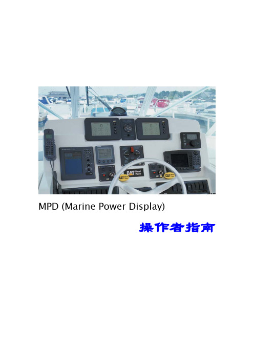
船桥、左舷、右舷、船塔、发动机室、后舱、驾驶桥楼、前舱 显示单位
英制、公制 航速单位
KNOTS、MPH、KPH
鲜俊林
第4页
nic.xian@
Marine Power Display操作者指南
C AT E R P I L L A R M A R I N E P O W E R D I S P L AY Operator’s Guide
SAE J1708 数据链路(有限参数)
鲜俊林
第2页
nic.xian@
Marine Power Display操作者指南
C AT E R P I L L A R M A R I N E P O W E R D I S P L AY Operator’s Guide
MARINE POWER DISPLAY CONFIGURATION AND OPERATION The Marine Power Display can accommodate up to three users with five screens for each. Three users can set up the Power Display screens to their preferences. The buttons have multiple functions dependent on which screen is displayed. The button primary functions for the gauge screens are:
3512发动机齿条同步, 单体泵和气门调整程序解析

( 2 ) Synchronization pin 同步销 ( 3 ) Cover 盖 ( 4 ) Fuel stop lever停止供应燃油杠
Fuel Injector Synchronization Procedure
单体泵齿条同步行程调整程序-3
4. Remove the valve covers
把正时螺丝(2)塞进飞轮壳的正时孔,用9S-9082盘车工具(4)和扭力扳手根据机组曲 轴转动方向-逆时针方向(标准运转)盘转至到正时螺丝(2)刚好能接触和用手轻轻的 扭进飞轮螺纹孔内.
1. Cover 盖 2. Timing bolt 正时螺丝 3. Plug 堵头 4. 9S-9082 Engine Turning Tool 盘车工具
8T-2684 Rack Synchronization Gauge 齿条同步行程测量工具 1. Injector synchronization is the setting of all fuel injector racks so each injector gives the same amount of fuel to each cylinder. Injector synchronization is done by setting each fuel injector rack to the same position. 调整单体泵齿条同步行程是为了让所有的单体泵提供 相同的供油量提供燃油给每个气缸. 单体泵齿条同步 行程是调整每个单体泵齿条行程在相同的位置.
Caterpillar 3512 Engine Adjustment 卡特彼勒3512发动机调整程序
1.单体泵齿条同步行程调整程序
2.寻找活塞在第1缸上止点
发动机气门间隙调整方法
发动机气门间隙调整方法汽车气门,也称作节气门,其作用是专门负责向发动机内输入燃料并排出废气,传统发动机每个汽缸只有一个进气门和一个排气门,这种制定结构相对简单,成本较低,修理方便,低速性能较好,缺点是功率很难提升,尤其是高转速时充气效率低、性能较弱。
为了提升进排气效率,现在多采纳多气门技术,常见的是每个汽缸布置有4个气门(也有单缸3或5个气门的制定,原理一样),4汽缸一共就是16个气门,我们在汽车资料上常常看到的“16V〞就表示发动机共16个气门。
这种多气门结构容易形成紧凑型燃烧室,喷油器布置在中央,这样可以令油气混合气燃烧更迅速、更均匀,各气门的重量和开度适当地减小,使气门开启或闭合的速度更快。
常见气门间隙检查和调整的方法有两种:逐缸调整法依据汽缸点火次序,确定某缸活塞在压缩上止点位置后,可对此缸进、排气门间隙进行调整;调妥之后摇转曲轴,按此法逐步调整其它各缸气门间隙。
采纳两次调整法摇转曲轴使第一缸活塞处于压缩上止点,飞轮记号与检查孔刻线对正,这时可调1、2、4、5、和8、9气门(指发动机气门由前向后排列顺序);然后摇转曲轴一圈,使六缸活塞处于压缩行程上止点,再调3、6、7、10“加两只〞(即11、12)气门,这实际上是记忆法调整。
调整时一边拧调整螺钉,一边用厚薄规插入气门杆端与摇臂之间来回拉动,感到有稍微阻力为宜,然后重新检查一遍,直到合适为止。
逐缸法必须摇转的曲轴次数多,检调所花费时间多,但关于磨损较严重的发动机,用逐缸法检调气门间隙比较准确。
两次法调整气门间隙比较省时省力,但关于不同车型必须记忆不同的可调气门顺序号,车型复杂,对修理人员记忆就有些难度。
2如何调气门间隙车辆在使用时,由于配气机构的零件磨损或调整螺钉松动,气门间隙就会发生变化,因此必须定期进行检查和调整。
顶置凸轮轴式气门间隙的调整方法a:拆下进排气门室盖和磁电机外罩;b:转动磁电机转子,使其外圆面上的"T"刻线与机壳上的刻线对准,此时活塞应处在压缩行程的上止点;c:将厚度为规定气门间隙值的塞尺当心地插入气门间隙内来回拉动,假设感到略有阻力时,说明间隙合适.d:假设间隙不合适,调整螺母,一边用小扳手转动调整螺钉,一边拉动塞尺检查间隙,待间隙合适后,再拧紧后间隙发生变化,应再用塞尺复测一次。
CAT3516技术手册)资料

SEBU6711-051999年5月操作说明和维护手册G3500发动机系列产品4WD1-Up(发动机)5JD1-Up(发动机)8LD1-Up(发动机)9TG1-Up(发动机)2TJ1-Up(发动机)7NJ1-Up(发动机)4EK1-Up(发动机)6JW1-Up(发动机)8PW1-Up(发动机)9AW1-Up(发动机)5ZZ1-Up(发动机)7SZ1-Up(发动机)8BZ1-Up(发动机)8JZ1-Up(发动机)重要的安全信息与产品运行、维护和修理相关的大多数事故都是由于忽视了基本的安全规则或者安全预防措施而引起的。
如果我们在事故发生之前就能够认识到潜在的危险情况,那么这些事故都是可以避免的。
因此,我们必须对产品潜在的危害提高警惕。
同时,操作人员和修理维护人员还必须参加相关的专业培训、具备一定的操作技能和拥有必要的操作工具。
对本产品的不正确的操作、加油、维护或者修理是非常危险的,可能会引起人身伤害甚至死亡。
除非您已经仔细阅读并理解了相关内容,请勿自行进行本产品的操作、加油、维护或者修理。
本手册中提供了有关本产品的安全预防措施和安全警报。
如果忽视了这些安全警报,将可能引起人身伤害或者死亡。
这些危险性的标志通常以一个“安全警报符号”和随后的“标志性语句”例如“危险”、“警报”或者“警告”来加以识别。
“警报”的安全报警标签如下所示:其具体含义如下:请注意提高警惕!请注意安全!将警报标签的具体内容可以以文字或者图片的形式显示。
可能引起产品损坏的操作已经用“注意”标签加以识别。
CATERPILLAR当然无法预见所有的可能带有潜在危险的具体情形。
因此,本公告中和产品本身所显示的警报并不能包含所有的潜在危险。
如果您使用的是由CATERPILLAR建议使用的工具、操作程序、操作方法以及操作技巧,那么您和他人可以对安全问题放心。
同时,您还必须保证自己的操作、加油、维护或者修理过程不会引起产品的损坏也不会引起其它安全问题。
CAT3406B柴油机大修教学文案
C A T3406B柴油机大修CAT3406B柴油机大修摘要:就CAT3406B柴油机大修工作进行总结,分析其故障原因,制定防范措施,详细记录维修步骤及装配技术要求,为该类柴油机维修工作提供经验及为设备日常管理提供参考。
关键词:卡特彼勒;柴油机;大修;故障分析;装配1.设备简介一海上作业设施消防用潜水多级离心泵,它是由卡特彼勒3406BTA柴油机带动的。
机组具体参数如下:(1)、泵型号:Floway Model 16 MKM-FP,4级潜水离心泵;设计流量、压力:2500 GPM、150 psig。
(2)、柴油机:412HP CAT 3406 BTA;启动方式:130psig公用气启动;转速:高速1770rpm,怠速985rpm;燃料箱:275 gallon,能保证柴油机连续工作11小时以上;冷却方式:水冷,冷却水与海水换热。
(3)、动力输出:动力输出由十字联轴节和一蜗轮蜗杆齿轮箱变向传动。
2.设备故障该柴油机在一次喷淋系统触发运转时冒黑烟,喷淋系统警报恢复后停机检查。
造成柴油机冒黑烟的因素很多,供油系统、燃烧系统、进排气系统等故障都可能导致柴油机出现冒黑烟故障,常见的有以下几种:(1)、进气系统A.空气过滤器问题;B.进气管有堵塞;C.进气温度过高;(2)、燃烧系统A.气门间隙误差;B.燃油质量;(3)、供油系统A.喷油提前角偏大或偏小;B.喷油嘴雾化不良;C.喷油泵供油量太大;本着先易后难的故障排查原则,检查顺序如下:(1)、其他柴油机无冒黑烟现象,排除燃油质量问题;(2)、检查空气进口过滤器,目测过滤器状况良好,进气胶管通畅,用气枪清洁过滤器;(3)、检查各缸气门间隙,间隙在误差范围内,按标准数据略微调整了气门间隙。
(4)、启动柴油机,状况无明显变化,空气进口吸气正常,排除过滤器堵塞,也排除了因气门间隙不对导致柴油燃烧不充分冒黑烟的可能;(5)、检查喷油嘴,更换了所有喷油嘴,重新调节气门间隙,启机运转状况无改变;图1 旧的喷油嘴(6)、两天后再次进行检查工作,发现空气进口过滤器有水泡过的迹象,且有少量盐分结晶;进气胶管也有结晶盐;顺着进气通道检查,拆开中冷器发现其散热片已被结晶盐堵塞。
卡特3512故障代码
卡特3512故障代码卡特彼勒柴油机故障代吗CID01FMI05----1缸喷油器开路(电流低于正常值) CID01FMI06----1缸喷油器短路(电流高于正常值) CID02FMI05----2缸喷油器开路(电流低于正常值)CID02FMI06----2缸喷油器短路(电流高于正常值) CID03FMI05----3缸喷油器开路(电流低于正常值) CID03FMI06----3缸喷油器短路(电流高于正常值)CID04FMI05----4缸喷油器开路(电流低于正常值) CID04FMI06----4缸喷油器短路(电流高于正常值) CID05FMI05----5缸喷油器开路(电流低于正常值)CID05FMI06----5缸喷油器短路(电流高于正常值) CID06FMI05----6缸喷油器开路(电流低于正常值) CID06FMI06----6缸喷油器短路(电流高于正常值)CID07FMI05----7缸喷油器开路(电流低于正常值) CID07FMI06----7缸喷油器短路(电流高于正常值) CID08FMI05----8缸喷油器开路(电流低于正常值)CID08FMI06----8缸喷油器短路(电流高于正常值) CID09FMI05----9缸喷油器开路(电流低于正常值) CID09FMI06----9缸喷油器短路(电流高于正常值)CID010FMI05----10缸喷油器开路(电流低于正常值) CID010FMI06----10 缸喷油器短路(电流高于正常值) CID011FMI05----11缸喷油器开路(电流低于正常值) 1CID011FMI06----11缸喷油器短路(电流高于正常值)CID012FMI05----12缸喷油器开路(电流低于正常值)CID012FMI06----12缸喷油器短路(电流高于正常值)CID013FMI05----13缸喷油器开路(电流低于正常值)CID013FMI06----13缸喷油器短路(电流高于正常值)CID014FMI05----14缸喷油器开路(电流低于正常值)CID014FMI06----14缸喷油器短路(电流高于正常值)CID015FMI05----15缸喷油器开路(电流低于正常值)CID015FMI06----15缸喷油器短路(电流高于正常值)CID016FMI05----16缸喷油器开路(电流低于正常值)CID016FMI06----16缸喷油器短路(电流高于正常值)CID91 FMI08--------油门输出信号—不正常信号CID94FMI002-------滤清后燃油压力---不正确信号CID94FMI03--滤清后燃油压力--电压高于正常值(对蓄电池正极开路)CID94FMI04--滤清后燃油压力--电压低于正常值(对地短路) CID94FMI13--滤清后燃油压力—偏离标定CID100FMI02--滤清后发动机机油压力--不正确信号(超出范围)CID100FMI03--滤清后发动机机油压力—电压高于正常值(对电池正极开路/短路)CID100FMI04--滤清后发动机机油压力--电压低于正常值(对地短路)CID100FMI13滤清后发动机机油压力--偏离指标CID101FMI03曲轴箱压力--电压高于正常值(对电池正极开路/短路) 2CID101FMI04曲轴箱压力--电压低于正常值(对地短路)CID101FMI13曲轴箱压力--偏离标定CID110FMI04冷却液温度--电压低于正常值(对地短路)CID110FMI03冷却液温度--电压高于正常值(对电池正极开路) CID168FMI00蓄电池电压高于正常范围CID168FMI01蓄电池电压低于正常范围CID168FMI02蓄电池电压--不正确信号(电压中断或零乱)CID190FMI02发动机主转速/正时传感器--不正确信号(信号丢失或损缺)CID190FMI03发动机主转速/正时传感器--电压高于正常值(对电池开路)CID190FMI08发动机主转速/正时传感器--不正确信号CID248FMI09 CAT数据传输系统--不正常更新CID253FMI02个性模块--不正确信号(匹配有误)检查用户或系统参流CID254FMI12 EMC--失效(有误)CID261FMI13正时传感器--偏离标定CID262FMI03模拟传感器--电压高于正常值(5伏传感器对电池正极短路)CID262FMI04模拟传感器--电压低于正常值(电流对地短路) CID263FMI03数字传感器--电压高于正常值(对电池正极短路) CID263FMI04数字传感器--电压低于正常值(电压对地短路) CID268FMI02编程参数--不正确信号3CID273FMI00增压器压缩机出口压力--高于正常范围CID273FMI03增压器压缩机出口压力--电压高于正常值(对电池正极开路/短路) CID273FMI04增压器压缩机出口压力--电压低于正常值(对地短路)CID273FMI13增压器压缩机出口压力--偏离标定CID274FMI03大气压力--电压高于正常值(对正极开路/短路) CID274FMI04大气压力--电压低于正常值(对地短路)CID274FMI13大气压力--偏离标定CID275FMI03右增压器压缩机出口压力--电压高于正常值 CID275FMI04右增压器压缩机出口压力--电压低于正常值 CID275FMI13右增压器压缩机出口压力--偏离标定CID276FMI03左增压器压缩机出口压力--电压高于正常值 CID276FMI04左增压器压缩机出口压力--电压低于正常值 CID276FMI13左增压器压缩机出口压力--偏离标定CID279FMI03后冷却器温度--电压高于正常值CID279FMI04后冷却器温度--电压低于正常值CID289FMI02未滤清燃油压力--不正确信号(安装有误)CID289FMI03未滤清燃油压力--电压高于正常值(对电池正极开路/短路)CID289FMI04未滤清燃油压力--电压低于正常值(对地短路) CID289FMI13未滤清燃油压力--偏离标定CID336FMI02 ESC开关输入不正确4CID337FMI02紧急停机输入--不正确信号CID338FMI05预润滑--电流低于正常值(继电器开路)CID338FMI06预润滑--电流高于正常值(继电器对地短路) CID338FMI11预润滑暂停--故障模式不能识别CID342FMI03发动机第二转速--电压高于正常信号CID342FMI02发动机第二转速--不正常信号CID444FMI05启动马达继电器--电流低于正常值(开路)CID444FMI06启动马达继电器--电流高于正常值(短路)CID446FMI05空气关停继电器--电流低于正常值(开路)CID446FMI06空气关停继电器--电流高于正常值(短路)CID542FMI02未滤清发动机机油压力--不正确信号(安装有误)CID542FMI03未滤清发动机机油压力--电压高于正常值(对电池正极开路/短路) CID542FMI04未滤清发动机机油压力--电压低于正常值(对地短路)CID542FMI13未滤清发动机机油压力--偏离标定CID545FMI05乙醚启动--电流低于正常值(继电器对电池正极开路/短路)CID545FMI06乙醚启动--电流高于正常值(对地短路)CID546FMI05乙醚保持(继电器对地开路)CID546FMI06乙醚保持(继电器对电池正极短路)CID827FMI03左排气温度--电压高于正常值CID827FMI04左排气温度--电压低于正常值5CID827FMI08左排气温度--不正常信号(异常) CID828FMI03右排气温度--电压高于正常值 CID828FMI04右排气温度--电压低于正常值 CID828FMI08右排气温度--不正常信号(异常) CID879FMI02数据链不正常CID1174FMI08燃油位置放大器--不正常信号6TAD1241型VOLVO柴油机故障代码代码;2,1原因;燃油中有水或燃油压力不足。
- 1、下载文档前请自行甄别文档内容的完整性,平台不提供额外的编辑、内容补充、找答案等附加服务。
- 2、"仅部分预览"的文档,不可在线预览部分如存在完整性等问题,可反馈申请退款(可完整预览的文档不适用该条件!)。
- 3、如文档侵犯您的权益,请联系客服反馈,我们会尽快为您处理(人工客服工作时间:9:00-18:30)。
Testing and Adjusting3500B and 3500C Marine Engines Valve Lash and Valve Bridge AdjustmentSMCS -1102-036Shutdown SISPreviousScreenProduct: MARINE AUXILIARY Model: 3516B MARINE AUXILIARY S2R Configuration:3516B Marine Auxiliary Engine S2R00001-UPMedia Number -RENR5078-06Publication Date -01/10/2009Date Updated -06/10/2009i02013998Illustration 1g00286271(1)147-2060Wrench(2)147-2059Torque Wrench(3)148-7211Bridge Nut Socket(4)145-5191Gauge Support(5)147-2056Dial Indicator(6)147-5536Indicator Contact Point(7)147-2057Indicator Contact Point(8)147-2058Indicator ExtensionTable1Note:The 145-5191Gauge Support (4),the 147-2057Indicator Contact Point (7),the 147-2058Indicator Extension (8),and the 147-5536Indicator Contact Point (6)are included in the 147-5482Valve Lash Gauge Group .Note:The 147-2056Dial Indicator or the 147-5537Dial Indicator (Metric,not shown)can be used with the 147-5482Valve Lash Gauge Group .There are two different design of valve bridges that are used.If the engine is equipped with an adjustable valve bridge (Illustration 2),proceed to the "Valve Bridge Adjustment".If the engine is equipped with a nonadjustable valve bridge (Illustration 3),proceed to the "Valve Lash Adjustment".Tools NeededQuantity 147-2060Wrench1 147-2059Torque Wrench1 148-7211Bridge Nut Socket1 145-5191Gauge Support1 147-2056Dial Indicator1 147-5536Indicator Contact Point1 147-2057Indicator Contact Point1 147-2058Indicator Extension1 147-5537Dial Indicator (not shown) 1Illustration2g01034327 Adjustable valve bridgeValve Bridge AdjustmentNote:When the 147-5482Valve Lash Gauge Group is used,it is not necessary for you to remove the rocker arm shaft assemblies.The valves must be fully closed when the adjustment is made.Refer to Testing and Adjusting,"Finding the Top Center Position for the No.1Piston".Installation1.Assemble the 147-2058Indicator Extension and the 147-5536Indicator Contact Point on the 147-2056Dial Indicator or on the 147-5537Dial Indicator.Illustration 3g0*******Nonadjustable valvebridge The Electronic Control Module produces high voltage.To prevent personal injury make sure the Electronic Control Module is not powered and do not come in contact with the fuel injector solenoid terminals while the engine is running.Illustration4g00286279 145-5191Gauge Support(1)Knurled knobIllustration5g00286280 (2)Valve cover base rear bolt holeIllustration6g00286281(3)147-5536Indicator Contact Point2.Install the 145-5191Gauge Support in the rear bolt hole (2).The rear bolt hole is located in the valve cover base.Adjust contact point (3)on the top edge of valve bridge (4).3.Loosen the locknut for the adjustment screw.Loosen the adjustment screw (5)by several turns.4.Apply a force of 5N (1lb)to 45N (10lb).Push down on the top contact surface of the valve bridge.Zero the indicator.5.Turn adjustment screw (5)in the clockwise direction until the dial indicator reads 0.038mm (0.0015inch).This measurement is equal to turning the adjustment screw 20to 30degrees clockwise after the screw contacts the end of the valve.(4)Top edge of the valvebridgeIllustration 7g0*******(5)Adjustmentscrew Illustration 8g0*******(6)148-7211Bridge Nut Socket6.Hold the adjustment screw with the 148-7211Bridge Nut Socket (6)in order to tighten the locknut to 30±4N·m (22±3lb ft).You may use a sliderule torque computer in order to determine the torque wrench dial reading for the different extensions.Refer to SpecialInstruction,SEHS7150,"Snap On Torque Computer".Valve Lash AdjustmentNote:Adjust the valve bridges before you make the valve lash adjustments.1.Ensure that the number 1piston is at the top center position.Refer to Testing and Adjusting,"Finding the Top Center Position for the No.1Piston".2.The number 1piston should be at the top center position of the correct stroke.Makeadjustments to the valves according to the chart:Refer to Testing and Adjusting,"Crankshaft Positions for Fuel Injector Adjustment and Valve Lash Setting".Note:Tap each rocker arm on the top of the adjustment screw before you make any e a soft hammer.Make sure that the lifter roller is seated against the base circle of thecamshaft.The Electronic Control Module produces high voltage.To prevent personal injury make sure the Electronic Control Module is not powered and do not come in contact with the fuel injector solenoid terminals while the engine is running.Table 2Valve Lash Setting:Engine StoppedValvesGauge Dimension Inlet0.50mm (0.020inch) Exhaust 1.00mm (0.040inch)3.Install the 145-5191Gauge Support (1).Use the 147-2056Dial Indicator or use the 147-5537Dial e the 147-2057Indicator Contact Point (2).Install the tool in the rear bolt hole.The rear bolt hole is located on the valve coverbase.Illustration 9g0*******(1)145-5191Gauge Support(2)147-2057Indicator ContactPoint Illustration 10g0*******(3)147-2060Wrench(4)147-2059Torque Wrench4.Move the rocker assembly upward and move the rocker arm assembly downward.Move the rocker assembly several times.The oil film is removed in order to get a true zero reading on the dial e the 147-2060Wrench (3)and use the 147-2059Torque Wrench (4).Install the socket wrench and install the torque wrench on the nut of the rocker arm.Apply upward pressure to the front of the rocker assembly.Set the dial indicator to zero.The weight of the torque wrench (4)allows the valve lash to be read.Do not apply any pressure on the torque wrench.5.Loosen the locknut.The locknut is located on the adjustment screw of the pushrod.Turn the adjustment screw until the valve lash is set to specifications.Tighten the nut for the adjustment screw to 70±15N·m (50±11lb ft ).The 147-2059Torque Wrench is preset to the torque that is required.Check the adjustmentagain.Illustration 11g0*******(3)147-2060Wrench(4)147-2059Torque Wrench Copyright 1993-2009Caterpillar Inc.All Rights Reserved.Private Network For SIS Licensees. Wed Dec 1619:19:37UTC+08002009。
