清华大学土木工程系结构力学(英)Chapter8_582602260
清华大学结构力学第8章渐进法分析

A
i
B
A
M AB iA
M BA iA
A
i
B
A
CAB
M BA M AB
1 2
CAB
M BA M AB
0
CAB
M BA M AB
1
在上面的讨论中可知,远端弯矩等于近端弯
矩乘传递系数,即 MBA CAB M。AB 清华大学结构力学第8章渐进法分 析
四、单结点力矩分配
MB=60kN.m
200kN
A
EI
3m
B
3m
20kN/m
EI C
6m
a)
200kN MB 60kN.m 20kN/m
B
A
B
150kN.m -90kN.m 150kN.m 150kN.m 90kN.m C
b)
用位移法解图a)所示结构时,首先在结点B加上 附加转动约束,锁住B使之不能转动。其产生的 反力矩MB等于各杆端固端力矩的代数和,见图 b)。
0.571
BC
3 7
0.429
M
F AB
1 8
2006Biblioteka 150kN.mMF BC
1 20 62 8
90kN.m
结点B约束力矩为:
M
F BA
1 8
200
6
150kN.m
结点B分配力矩为:
MB (150 90)清华6大0学k结N构.m力学第8章渐进M法分B 60kN.m
析
3)运算格式
分配系数 固端弯矩 分配传递
A
-150
-17.13
杆端弯矩 -167.13
BA BC
0.571 0.429
150 -90 -34.26 -25.74
清华大学结构力学

38
3
目录
结构力学(II) 第十 章 矩阵位移法 第十三章 结构的动力计算 第十五章 结构的塑性分析与极限荷载
结构力学教程(I)、(II) 龙驭球 包世华 主编 龙驭球 包世华 匡文起 袁驷 编著
高等教育出版社
4
第一章 绪 论
§1-1 结构力学的内容和学习方法
§1-2 结构计算简图
5
§1-1 结构力学的内容和学习方法
一、结构
建筑物或构筑物中 承受、传递荷载而起 骨架作用的部分称为 结构。如:房屋中的 框架结构、桥梁、大 坝等。
6
万里长城 7
天安门城楼
8
国家大剧院
9
三峡大坝
10
印度泰姬陵 11
意大利比萨斜塔
12
凯旋门
13
埃菲尔铁塔 14
吉隆坡石油双塔 15
桥梁 16
赵州桥
17
青马大桥
18
旧金山大桥
2)荷载作用下杆件截面存在弯矩、剪力和轴力。
33
3. 拱
FH FV
FP
三铰拱
FH
FV
拉杆
拉杆拱
拱的特点:
无铰拱
1) 拱的轴线为曲线,在竖向荷载作用下支座有
水平推力F(H 见图);
2) 水平推力大大改变了拱的受力特性。
34
4. 桁架和组合结构
静定桁架
超静定桁架 组合结构
35
特点:
1) 桁架由直杆组成,所有结点都是铰结点,当 荷载作用于结点时,各杆只受轴力;
一、支座和支座反力
支座定义:把结构与基础联结起来的装置。 1. 固定支座
B
A
实际形状
结构力学课件
A
(b)刚结点
A
(c) 组合结点 图 1-5
34
结构力学
1-2-6
支座的简化及分类
理论力学中已经引入了支座的计算简图,现 归纳、补充如下: 支座是将结构和基础联系起来的装置,其作 用是将结构固定在基础上,并将结构上的荷载传
递到基础和地基。支座对结构的约束力称为支座
反力,支座反力总是沿着它所限制的位移方向。
在结构计算中,为了简化,对组成各构件的材 料一般都假设为连续的、均匀的、各向同性的、完 全弹性或弹塑性的。
2016/1/14
结构力学
42
1-2-8
荷载的简化
结构承受的荷载可分为体积力和表面力两大类。 在杆件结构中把杆件简化为轴线,因此不管是体积 力还是表面力都可以简化为作用在杆件轴线上的力。 荷载按其分布情况可简化为集中荷载和分布荷 载。
2016/1/14
结构力学
5
在水工结构方面: ① 公元前256-251年秦朝修建的岷江水利枢纽工程都江堰创 造了用竹笼装卵石堆砌的堤坝结构,使用至今,其结构 之简单,规模之宏伟,堪称世界之最。 在桥梁结构方面: ① 公元605-617年隋朝修建的河北赵县安济桥(也称赵州桥) 为敞肩石拱桥,造型优美、结构合理。 ② 宋代的广东潮州广济桥(开关活动式)。 ③ 福建泉州万安桥(即洛阳桥,筏形基础,砺房胶固), 其独特结构型式在世界上都绝无仅有。
2016/1/14
ห้องสมุดไป่ตู้
结构力学
17
结构力学研究对象涉及较广,根据所涉及范围, 通常将结构力学分为“狭义结构力学”、“广义结
构力学”和“现代结构力学”。
狭义结构力学 其研究对象为由杆件所组成的体系。
这种体系能承担外界荷载作用,
结构力学ppt课件

目录
• 结构力学简介 • 结构力学的基本原理 • 结构分析的方法 • 结构力学的应用 • 结构力学的挑战与未来发展 • 结构力学案例分析
01
结构力学简介
什么是结构力学
01
结构力学是研究工程结构在各种外力作用下产生的响
应的一门学科。
02
它主要涉及结构的强度、刚度和稳定性等方面的分析
04
有限元法
有限元法是一种将结构分解为有限个小 的单元,并对每个单元进行力学分析的 方法。
有限元法具有适用范围广、精度较高等 优点,但也存在计算量大、需要较强的 计算机能力等缺点。
通过对所有单元的力学行为进行组合, 可以得到结构的整体力学行为。
它适用于对复杂结构进行分析,例如板 壳结构、三维实体等。
结构力学的历史与发展
结构力学起源于19世纪中叶,随着土木工程和机械工程的发展而逐渐形成。
早期的结构力学主。
目前,结构力学已经广泛应用于各个工程领域,包括建筑、桥梁、机械、航空航天等。同时,结构力学 的研究也在不断深入和发展,以适应各种复杂工程结构的需要。
案例一:桥梁的力学分析
总结词
桥梁结构是力学分析的重要案例,涉及到多种力学因素,包括静载、动载、应 力、应变等。
详细描述
桥梁的力学分析需要考虑多种因素,包括桥梁的跨度、桥墩的支撑方式、桥梁 的材料性质等。在分析过程中,需要建立力学模型,进行静载和动载测试,并 运用结构力学的基本原理进行优化设计。
案例二:航空发动机的力学设计
强度理论
01
强度理论是研究结构在外力作用下达到破坏时的强度条件的科学。
02
强度理论的基本方程包括最大正应力理论、最大剪切应力理论、形状改变比能 理论和最大拉应力理论,用于描述结构在不同外力作用下达到破坏时的条件。
清华大学土木工程系结构力学(英)Chapter7_812904391

Basic Concepts for the Force Method Construction of M,V,N diagrams
M - diag. 1) Direct-plotting 2) superposition
M M1 X 1 M 2 X 2 M P
V - diag. 1) Direct-plotting 2) Superposition N - diag. 1) Direct-plotting 2) Superposition
12
Basic Concepts for the Force Method
11 1n X1 D1P Flexibility matrix D NP n1 nn X N
q C
B
C
q
B X1
X2
Compatibility Equation:
A
A
Primary
D 1 11 X1 12 X 2 D 1 p 0 D 2 21 X1 22 X 2 D 2 p 0
Disp. due to X2 = 1
Disp. due to load
ij
— Non-diagonal coefficients
ij ji
Reciprocal theorem:
13
Basic Concepts for the Force Method
Several points:
(5) The force method = the method of consistent displacement
结构力学(完整资料).doc
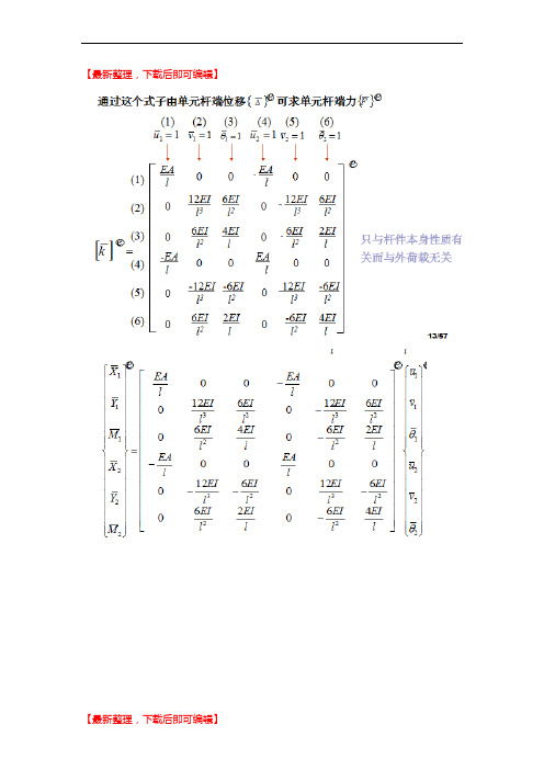
【最新整理,下载后即可编辑】§13-4 连续梁的整体刚度矩阵即传统位移法:根据每个结点位移对附加约束上的约束力{F}的贡献大小进行叠加而计算所得。
一、单元集成法的力学模型和基本概念1.首先只考虑于是其中由前面的单元刚度矩阵所得,则进一步得到所以最终得到2.则这是最后总结如下的形式来作最终的计算§13-5 刚架的整体刚度矩阵思路要点:(1)设各单元已形成了整体坐标系下的单元刚度矩阵;与连续梁相比: (1)各单元考虑轴向变形;(2)每个刚结点有三个位移; (3)要采用整体坐标;(4)要处理非刚结点的特殊情况。
一、结点位移分量的统一编码——总码整体结构的结点位移向量为:相应地结点力向量为:规定:对于已知为零的结点位移分量,其总码均编为零。
其中每个单元的刚度为以下其中定位向量为:最终进行叠加求得整体刚度矩阵代入数字得定位向量:§13-6 等效结点荷载结构体系刚度方程:{F}= [K]{∆} (1)表示结点位移{∆}和结点力{F}之间的关系,反映了结构的刚度性质,而不涉及原结构上作用的实际荷载,并不是原结构的位移法基本方程。
一、位移法基本方程} ={0} (2)[K]{∆} +{FP用图来表达以上思想:二、 等效结点荷载的概念显然 {P }= –{F P }………解决了计算等效结点荷载的问题 等效原则是两种荷载在基本体系中产生相同的结点约束力 三、按单元集成法求整体结构的等效结点荷载{P } (1)局部坐标单元的等效结点荷载(2)整体坐标单元的等效结点荷载(3) 结构的等效结点荷载{P }{}[]{}P T P T=依次将每个单元等效结点荷载中的元素按照单元定位向量在结构的等效结点荷载中定位叠加。
§13-7 计算步骤和算例1 确定整体和局部坐标系、单元和结点位移编码2 形成刚度矩阵(1)形成局部坐标系下的单元刚度矩阵(2)形成整体坐标系下的单元刚度矩阵(3)“换码重排座”,形成整体结构的刚度矩阵3 形成等效结点荷载(1)形成局部坐标系下的单元固端力(2)形成整体坐标系下的单元等效结点荷载(3) “换码重排座”,形成整体结构的等效结点荷载4 解整体刚度方程,求结点位移5 求各单元的杆端内力(1)整体坐标系下的单元杆端位移(2)局部坐标系下的单元杆端位移(3)局部坐标系下的单元杆端内力§13-8 忽略轴向变形时矩形刚架的整体分析14 超静定结构总论§14-1 超静定结构解法的分类和比较超静定结构计算方法分类各种结构型式所选用的适宜解法说明:手算时,凡是多余约束多、结点位移少的结构用位移法;反之用力法。
清华结构力学作业

程序结构力学期中大作业——平面刚架计算程序1、简要程序说明《结构力学求解器》教学版有前后处理界面,缺核心计算程序SM90.exe,本程序即编制核心计算程序SM90.exe。
1.1 处理范围限制荷载:支持所有结点荷载、包括杆端位移的四种单元荷载结点连接:支持所有非斜向的各种连接支座约束:支持除了斜支座之外的各种支座1.2 计算求解简要流程从文件“SM90.ipt”中读取、处理并储存结构的结点及单元信息。
使用矩阵位移法,首先集成整体总结点荷载向量P,集成整体刚度矩阵K,使用LDL T分解法求解得到整体结点位移向量∆,然后再根据∆先得到整体坐标下杆端位移向量∆e,再由杆端位移向量、局部单元刚度矩阵、单元固端力向量得到局部坐标系下杆端内力向量。
2、源代码模块及程序清单3、输入的结构数据信息3.1 结构、荷载数据及计算简图其它:柱刚度:EA=105().()kN m215104kN,EI=⨯⋅梁刚度:EA=106()kN m2.()kN,EI=⨯⋅10104支座沉降:c=001.()m3.2 输入数据文件内容(未处理)结点,1,0,0结点,2,0,5结点,3,6,0结点,4,6,4结点,5,6,8结点,6,6,12结点,7,6,16结点,8,13,0结点,9,13,4结点,10,13,8结点,11,13,12结点,12,13,16结点,13,16,0结点,14,16,2单元,1,2,1,1,0,1,1,1单元,2,5,1,1,1,1,1,0单元,3,4,1,1,1,1,1,1单元,4,5,1,1,1,1,1,1单元,5,6,1,1,1,1,1,1单元,6,7,1,1,1,1,1,0单元,4,9,1,1,1,1,1,1单元,5,10,1,1,1,1,1,1单元,6,11,1,1,1,1,1,1单元,7,12,1,1,1,1,1,1单元,8,9,1,1,0,1,1,1单元,9,10,1,1,1,1,1,1单元,10,11,1,1,1,1,1,1单元,11,12,1,1,1,1,1,1单元,9,14,1,1,0,1,1,1单元,13,14,1,1,1,1,1,1结点支承,1,4,0,0,0结点支承,3,6,0,0,0,0结点支承,8,4,0,0,0结点支承,13,6,0,0,0,0结点荷载,2,1,10,0结点荷载,7,1,40,0单元荷载,10,1,60,1/3,90单元荷载,10,1,60,2/3,90单元荷载,9,1,60,1/2,90单元荷载,8,3,5,0,1,90单元荷载,7,3,5,0,1,90单元荷载,5,3,2,0,1,90单元荷载,6,3,2,0,1,90单元荷载,15,3,3,0,1,90单元材料性质,1,1,100000,15000,0,0,-1单元材料性质,3,6,100000,15000,0,0,-1单元材料性质,11,14,100000,15000,0,0,-1单元材料性质,16,16,100000,15000,0,0,-1单元材料性质,2,2,1000000,10000,0,0,-1单元材料性质,15,15,1000000,10000,0,0,-1单元材料性质,7,10,1000000,10000,0,0,-1结点支承,3,6,0,0,0.01,03.3 输入数据文件内容(处理后:SM90.IPT)116 17 35 2 90.000000000000000E+000 0.000000000000000E+000 0 010.000000000000000E+000 5.00000000000000 2 346.00000000000000 0.000000000000000E+000 0 06.00000000000000 4.00000000000000 8 9106.00000000000000 8.00000000000000 5 676.00000000000000 8.00000000000000 5 6116.00000000000000 12.0000000000000 12 13146.00000000000000 16.0000000000000 15 16176.00000000000000 16.0000000000000 15 162713.0000000000000 0.000000000000000E+000 0 03113.0000000000000 4.00000000000000 18 192013.0000000000000 4.00000000000000 18 193213.0000000000000 8.00000000000000 21 222313.0000000000000 12.0000000000000 24 252613.0000000000000 16.0000000000000 28 293016.0000000000000 0.000000000000000E+000 0 016.0000000000000 2.00000000000000 33 34351 2 100000.000000000 15000.00000000002 5 1000000.00000000 10000.00000000003 4 100000.000000000 15000.00000000004 6 100000.000000000 15000.00000000006 7 100000.000000000 15000.00000000007 8 100000.000000000 15000.00000000004 11 1000000.00000000 10000.00000000006 13 1000000.00000000 10000.00000000007 14 1000000.00000000 10000.00000000009 15 1000000.00000000 10000.000000000010 11 100000.000000000 15000.000000000011 13 100000.000000000 15000.000000000013 14 100000.000000000 15000.000000000014 15 100000.000000000 15000.000000000012 17 1000000.00000000 10000.000000000016 17 100000.000000000 15000.00000000002 1 10.00000000000008 1 40.000000000000010 2 0.333333333333333 -60.000000000000010 2 0.666666666666667 -60.00000000000009 2 0.500000000000000 -60.00000000000008 1 1.00000000000000 -5.000000000000007 1 1.00000000000000 -5.000000000000005 1 1.00000000000000 -2.000000000000006 1 1.00000000000000 -2.0000000000000015 1 1.00000000000000 -3.000000000000003 3 0 1.000000000000000E-0024、计算结果4.1 输出数据文件内容(SMCAI90.OUT)10 00.000000000000000E+000 0.000000000000000E+000 -1.312320379407611E-002 5.560652234870134E-002 2.304558378405893E-004 -7.117505821068581E-003 5.560652234870134E-002 2.304558378405893E-004 -7.117505821068581E-003 5.278394963143841E-002 5.869045961093688E-003 4.968728206911202E-003 0.000000000000000E+000 0.000000000000000E+000 0.000000000000000E+000 6.134302073665104E-003 7.774337023929546E-003 -6.220921272818899E-003 6.134302073665104E-003 7.774337023929546E-003 -6.220921272818899E-0035.278394963143841E-002 5.869045961093688E-003 -1.281184195691321E-002 5.278394963143841E-002 5.869045961093688E-003 -1.281184195691321E-002 0.110389250192221 3.881789234098302E-003 -1.238265778050635E-002 0.110389250192221 3.881789234098302E-003 -1.238265778050635E-002 0.153055590585021 2.237297589939866E-003 -9.630770979269111E-0036.134302073665104E-0037.774337023929546E-003 -6.220921272818899E-003 5.841122486500181E-003 -5.232962938233666E-003 -5.246190249735726E-003 5.278394963143841E-002 5.869045961093688E-003 -1.281184195691321E-002 5.276332645090513E-002 -1.211203654567029E-002 -1.205485451586346E-002 0.110389250192221 3.881789234098302E-003 -1.238265778050635E-002 0.110502106300783 -1.732477981867489E-002 -1.117824150760299E-002 0.153055590585021 2.237297589939866E-003 -2.048707379649037E-002 0.152720805404088 -2.048028817451645E-002 -1.428627258452916E-003 0.000000000000000E+000 0.000000000000000E+000 4.326741924302934E-004 5.841122486500181E-003 -5.232962938233666E-003 -5.246190249735726E-003 5.841122486500181E-003 -5.232962938233666E-003 -5.246190249735726E-003 5.276332645090513E-002 -1.211203654567029E-002 -1.205485451586346E-002 5.276332645090513E-002 -1.211203654567029E-002 -1.205485451586346E-002 0.110502106300783 -1.732477981867489E-002 -1.117824150760299E-002 0.110502106300783 -1.732477981867489E-002 -1.117824150760299E-002 0.152720805404088 -2.048028817451645E-002 -1.428627258452916E-003 5.841122486500181E-003 -5.232962938233666E-003 3.549261962267918E-003 7.823052813148474E-003 -1.542869377984182E-003 -4.215008775865264E-003 0.000000000000000E+000 0.000000000000000E+000 0.000000000000000E+000 7.823052813148474E-003 -1.542869377984182E-003 -4.215008775865264E-003 4.60911675681179 7.20683756760904 2.842170943040401E-014 4.60911675681179 -7.20683756760904 36.0341878380452-0.437020751516684 -5.37165956799102 -36.0341878380452-0.437020751516684 5.37165956799102 -3.552713678800501E-015 -55.6415744017613 -17.7399575774232 -12.1514603817755-55.6415744017613 17.7399575774232 -58.8083699279173-47.6322765708965 24.1428405889943 73.0016337433423-47.6322765708965 -24.1428405889943 23.5697286126350-49.6814181748847 24.2958468042149 41.6489196135707-49.6814181748847 -16.2958468042149 39.5344676032887-41.1122911039609 0.173545581013641 -15.3058176759457-41.1122911039609 7.82645441898636 1.896260926059767E-013 -41.8827981664175 8.00929783086485 -14.1932638154252-41.8827981664175 26.9907021691352 -52.2416513685209-2.94616864761065 -6.65825836080036 -65.2186482262056-2.94616864761065 41.6582583608004 -103.88916029939716.1223012232022 8.56912707092378 -24.2286499273430 16.1223012232022 51.4308729290762 -125.787460576191-47.8264544189915 41.1122911039609 -3.197442310920451E-014-47.8264544189915 78.8877088960391 -132.213962272274-130.824073455842 -10.6478708290613 -2.842170943040401E-014 -130.824073455842 10.6478708290613 -42.5914833162452-171.976840185916 34.6503218433935 94.8331346847660-171.976840185916 -34.6503218433935 43.7681526888080-130.318581825115 31.7041531957828 60.1210076105888-130.318581825115 -31.7041531957828 66.6956051725423-78.8877088960390 47.8264544189804 59.0918554036481-78.8877088960390 -47.8264544189804 132.213962272274-110.338164658006 -8.33948062935629 -3.996802888650564E-015 -110.338164658006 19.1561344557483 -49.5684250198828-77.1434688992091 81.1809908388722 112.793556657862-77.1434688992091 -81.1809908388722 49.5684250198828 4.2 结构内力图12.15弯矩图x剪力图轴力图1314。
结构力学课件清华大学龙驭球版本

§2.3无多余约束几何不变体系的组成规则
图a为一无多余约束的几何不变体系 将杆AC,AB,BC均看成刚片,就成为三刚
A
图a
片组成的无多余约束的几何不变体系
一、三刚片以不在一条直线上的三铰 C
B
相联,组成无多余约束的几何不
变体系。
三铰共线瞬变体系
三刚片以三对平行链杆相联 瞬变体系
两平行链杆于两铰连线平行, 瞬变1体3 系
y x
yx 图a
yX
o
y
x
图b
四、约束:在体系内部加入的减少自由度的装置
多余约束:不减少体系自 由度的约束称为多余约束。
注意:多余约束将影响结构的 受力与变形。
a A
4
1、单链杆:仅在两处与其它物体用铰相连,不论其形 状和铰的位置如何。
一根链杆可以减少
体系一个自由度,相 当于一个约束。!
Ⅰ
15
3
4
几个基本概念 体系的计算自由度 无多余约束的几何不 变体系的组成规则 分析举例
1
§2.1构造分析的几个基本概念
一、构造分析的目的 1、研究结构 正确的连接方式,确保所设计的结构能承受
荷载,维持平衡,不至于发生刚体运动。 2、在结构计算时,可根据其几何组成情况,选择适当的
计算方法;分析其组成顺序,寻找简便的解题途径。 二、体系的分类:在忽略变形的前提下,体系可分为两类:
的内力, 故几何常变体系和几 何瞬变体系不能作为建筑结 构使用.
只有几何不变体系才 能作为建筑结构使用!!
β
PA
β
Δ是微量
P N
N
3
三、自由度:所谓体系的自由度是指体系运动时,可以 独立改变的几何参数的数目; 即确定体系位置所需独立坐 标的数目。
结构力学导论

结构力学导论M. S. Kazimi, N.E. Todreas 和 L. Wolf 著MIT俞冀阳译清华大学工程物理系1.概念定义 (3)1.1 应力状态概念 (6)1.2 主应力, 主位面和主方向 (8)1.3 应变的基本考虑 (8)1.4 平面应力 (10)1.5 Mohr圆 (11)1.6 八面体位面和八面体应力 (16)1.7 主应变和主位面 (16)结论 (17)2.弹性应力-应变关系 (18)2.1广义虎克定律 (18)2.2 体积膨胀模量(体模量) (21)3.薄壁圆柱体和球体 (22)3.1 应力 (22)3.2 变形和应变 (23)3.3 两端封闭的圆柱的端头效应 (25)4.径向承压下的厚壁圆柱体[参考书1, PP.293-300] (28)4.1 位移方法 (29)4.2 应力方法 (31)5.热应力 (32)5.1 应力分布 (35)5.2 边界条件 (37)5.3 最后结果 (38)6.设计过程 (39)6.1 静态失效和失效理论 (40)6.2 二轴和三轴载荷下的失效预测 (42)6.3 最大法向应力理论 (Rankine) (43)6.4 最大剪应力理论 (Coulomb理论, 后来的Tresca 理论) (46)6.5 Mohr理论和内摩擦理论 (48)6.6 最大法向应变理论 (Saint-Vanent理论) (48)6.7 全部应变能理论(Beltrami 理论) (50)6.8 最大变形能理论(最大八面体剪切应力理论Van Mises, Hencky) (50)6.9 失效理论的比较 (53)6.10 失效理论在厚壁容器中的应用 (55)6.11 薄壁圆柱容器的失效预测 (62)6.12 薄壁圆柱容器的安全因子的例题 (64)参考书 (65)1. 概念定义结构力学是描述一个结构材料所受的外力、内力和变形之间的关系的。
因此有必要澄清几个描述这些量的概念。
在本文的大部分内容里面,结构力学指的是固体力学,因为只有固体能够承受平行于表面的负载。
结构力学Chapter_1_Introduction

Chapter 1 IntroductionContents§ 1-1 Main objectives and primary tasks of structural mechanics (1)§ 1-2 Analytical model and line diagram (2)§ 1-3 Classification of structures and loads (9)1-3-1 Classification of structures (9)1-3-2 Classification of loads (10)§ 1-4 Basic assumptions (11)Problems (15)§ 1-1 Main objectives and primary tasks of structural mechanicsA structure refers to a system of load carrying/transferring components that frame engineering buildings of various types of occupancy. Typical examples of structures include, but not limited to, the frames formed by floor slabs, beams, columns, shear walls and foundations, etc., of residential constructions, dams and flood gates of hydraulic constructions, bridges, tunnels and culverts of highways and railways, and the load carrying frames of automobiles and aircrafts, etc.The mechanical properties and load carrying capacity of engineering structures are closely linked to their geometric characteristics, based on which general structures can be divided into three categories:(1) Skeletal structures, which are consisted of a certain number of interconnected skeletal members. The geometric characteristic of a skeletal member is that its cross-sectional dimension is much smaller than its length. Typical examples of skeletal members and structures include beams, rigidly connected frames, arches and trusses, etc.(2) Plate and shell structures, which are also referred to as thin-wall structures. The geometric characteristic of a thin-wall structure is that its thickness is much smaller than the other two dimensions of it. The floor slabs, hemispherical roof diaphragms (Figure 1-1) and the shells of plane fuselage and ship hull all fall into this category.(3) Solid structures, also known as three-dimensional continuum structures, of which the length, width, and height are in similar size. Gravity retaining walls (Figure 1-2) and gravity dams of hydraulic constructions are examples of solid structures.Figure 1-1 Figure 1-21- 1Structural mechanics is mainly focused on the study of reasonable configuration of structures and their performance in regard to the internal forces, deformation, dynamic responses and stability when under external loads and/or other external effects, such as support movements and temperature changes. The objective of the study is to make the structures to meet the requirements for safety, serviceability and economic issues. More specifically, the primary tasks of structural mechanics include the following aspects:(1) Establish a rational form for a structure considering the functional requirements and occupancy of the structure.(2) Investigate the theories and methods of calculation of the internal forces, deformation, dynamic responses and stability of the structures.(3) Investigate the theories and methods of determination of the external actions based on the structural responses, and vice versa, and those of control of structural responses.Structural mechanics is an important professional basic course of the discipline of civil engineering. It is closely linked with several prerequisite courses, including theoretical mechanics and mechanics of materials, and the subsequent elastic and plastic mechanics. The theoretical mechanics and mechanics of materials are considered as fundamental mechanics while structural mechanics is mostly focused on skeletal structures and therefore is sometimes referred to as special structural mechanics; while the elastic and plastic mechanics mostly deals with continuum structures and plate and shell structures.Advances in modern engineering technologies and rapid development of computer technologies have had a profound impact on the discipline of structural mechanics. On one hand, analysis of massive engineering structures under actions of complex external factors requires emphasizing the integrated application of basic concepts of structural mechanics and theories of conceptual engineering design. On the other hand, the rapid increase in computing capacity requires the development of compatible theories and methods of structural mechanics. As a result, the traditional structural mechanics has been boosted towards directions, including the conceptual structural mechanics and computational structural mechanics.Many fundamental changes have taken place in the roles and functions of scientific and technical personnel in the field of civil engineering due to the fast development of science and technologies. The teaching of structural mechanics should therefore focus on the basic concepts of mechanics and their rational applications, in conjunction with the cognitive rules of the objective world and context of engineering practice, and eventually aims at improving the qualities and abilities of the students as an essential goal.§ 1-2 Analytical model and line diagramIn the real sense, the load state of a structure is often very complex. It will be difficult while unnecessary in many cases to analyze the structures in full accordance with the actual states of them, and thus certain simplifications and assumptions need to be made before analyzing the structural responses. Often, during the analysis some 1- 2secondary factors of actual structures are ignored under the premise that the structural responses can still be reflected correctly. Such a simplified representation of an actual structure for structural analysis purposes is called an analytical model. In analysis of mechanics, an analytical model is representative of the actual structure. Therefore, it is a key issue and should be solved first to choose and establish a rational analytical model.The principles of selection of an analytical model include as following:(1) Retain the main factors and omit the secondary factors so that the analytical model can reflect the essential features of the structural responses, such as internal forces.(2) To simplify the analytical model as much as possible without affecting its feasibility for structural analysis.In addition, different analytical models can be used for the same structure based on the requirements and specific circumstances. For example, in the preliminary design of a structure, a relatively coarse analytical model can be used; while in the construction design, a more precise analytical model should be used. Simplified analytical models can be used for hand computation while more precise analytical models can be constructed for computerized calculation. For dynamic analyses, the analytical models can be more simplified since the analysis is often complicated and time-consuming, while for static analysis, more precise analytical models can be used as the calculation is simple and fast.An analytical model comprises simplification of actual structures in many aspects and will be introduced separately as following.1. Structural configurationsSkeletal structures can be further divided into plane and spatial skeletal structures. Generally, all actual structures are spatial structures since they need to resist loads from all directions. However, in most cases, spatial constraints that are secondary to the structural performance can often be ignored or converted into one plane, by which an actual structure can then be broken down into several plane structures. In such way, the structural analysis can be greatly simplified.2. Structural members: line diagramsMembers of a skeletal structure can normally be represented by lines coinciding with their centroidal axes. The lengths of the members are expressed as the distances between the intersection points of them and adjacent members.3. ConnectionsA connection refers to the intersection amongst the members. Although the detailed configurations of the connections of timber, steel and concrete structures are quite different, their analytical models can normally be classified into two types:(1) Pin (hinge) connectionsThe characteristic of a pin connection is that all connected members can rotate freely around the connection, and therefore it is normally represented by an idealized smooth hinge. This idealized connection, however, is very difficult to achieve in practical engineering. For example, speaking of the intermediate connection of the bottom chord of a timber roof truss, as shown in Figure 1-3a, it is apparent that the1- 3Figure 1-4a shows the details of a connection between a side column and a beam of a reinforced concrete multistory frame structure. Since the concrete of the side column and beam are cast monolithically and the reinforcing bars extend into the column no less than the required anchorage length, it is ensured that the beam and the column are firmly linked together. In this case, the connection is considered as a rigid connection and its analytical model is shown in Figure 1-4b.4. SupportsA support refers to the connection between a structure and the foundation. The loads applied onto a structural are eventually passed via supports to the foundation and soil underneath. The counterforces passed from the supports to the structure are referred to as reaction forces. For plane structures, there are mainly five types of supports:(1) Roller supportExamples of roller supports include roller bearing (Figure 1-5a) and roll shaft bearing (Figure 1-5b) used in bridges.1- 4(4) Sliding supportFigure 1-8a shows schematically a sliding support (also known as a directional pin support). This type of support limits the rotation and movement along one direction while allows sliding in the other direction of the support. For example, the structure shown in Figure 1-8a cannot rotate or move vertically at the support while it can have a small amount of sliding along the horizontal direction. This type of support1- 5(5) Elastic supportAn elastic support is used when the deformation of the support cannot be ignored for structural analysis purposes. Shown in Figure 1-9a is a bridge deck structure, for which the deck loads are passed through the longitudinal beams to the horizontal beams and girders, and eventually to the piers of the bridge. In the load transfer path, the horizontal beams support the longitudinal beams and the resulting deformation of the horizontal beams may lead to vertical displacements of the longitudinal beams. In this case, each of the horizontal beams is equivalent to a spring support to the longitudinal beams. Since this type of supports has certain ability to resist transverse movements, they are referred to as an anti-sliding elastic support. For example, the intermediate supports of the longitudinal beam shown in Figure 1-9b all fall into this category. Another type of elastic supports has certain ability to resist torsional movements, known as anti-rotation elastic support.1- 65. LoadsThe floor loads of engineering buildings can generally be simplified as uniformly distributed vertical load; the lateral wind load can be simplified along the height of the buildings as uniformly distributed (in several segments), and so on.To illustrate the process of simplification of structural loads, a single story reinforced concrete industrial workshop, as shown in Figure 1-10, is used as an example. Normally, a reinforced concrete industrial workshop is spatial and consists of roof trusses, roof sheathing panels, columns, crane beams and bracing system, etc. Vertical roof loads are passed first from the sheathing panels to the roof trusses, and then to the columns at both ends of the trusses, and eventually to the foundation. When the workshop is subjected to lateral wind loads, the loads on the roof sheathing panels will be transferred to the upper ends of the columns via roof trusses; while the wind loads on the sidewalls are generally simplified as uniform distributed loads and are transferred to the columns via the walls and eventually to the foundation. When these two types of loads act separately, all plane frames (comprising trusses and columns) except those at the sides of the workshop will generate almost the same internal forces and deformation; therefore, the structural analysis of the building can be based on the analysis of one of these plane frames. Thus, a spatial problem can be simplified to a plane problem. It is well known that the longitudinal connections (mostly achieved by bracings) of the workshop is relatively weak and cannot provide sufficient integrity. Therefore, when the workshop is subjected to vertical or horizontal crane loads, it is conservative to assume that all or a certain percentage of the crane loads are resisted by the frame right underneath the crane(s). Thus, the workshop can still be analyzed as a plane system.1- 71- 8 Figure 1-10 1Fixed steel skylightRibbed sideboard Sheathing panel ColumnWindowBeamDitch Exterior wall LintelSteel bracketCullis board CranebeamGround Concrete padCup-shaped foundation Crane ladderWind column§ 1-3 Classification of structures and loads1-3-1 Classification of structures2. ArchesNormally the centroidal axis of an arch is curved. Arches will have horizontal reaction force under vertical loads, which helps to reduce the bending moments on the cross-sections (Figure 1-13).1- 93. Rigid framesA rigid frame usually consists of straight members. Its configuration is characterized by rigid connections at intersections of members (Figure 1-14). Sometimes a rigid frame is also called a frame.Figure 1-13 Figure 1-144. TrussesTrusses consist of straight members, which are all pin-connected. When a truss is subjected to nodal forces only, there will be only axial forces in truss members (Figure 1-15).5. Composite structuresA composite structure comprises truss members and beams (Figure 1-16a), or truss members and rigid frame members (Figure 1-16b). The feature of its load state is that its truss members only take axial force and all the other flexural members can resist axial force, shear force and bending moments simultaneously.In addition to the five types of skeletal structures mentioned above, which are the most basic, there are more complex ones, such as suspension cable structures.Figure 1-16Skeletal structures can be plane or spatial. When the centroidal axes of the members and the applied loads are in the same plane, it is known as a plane skeletal structure, or simply a plane structure. Those do not meet these conditions are known as spatial skeletal structures, or simply spatial structures (see § 3-6).1-3-2 Classification of loadsLoads refer to the external forces acting on a structure. For example, the 1- 10self-weight of a structure, crane loads of industrial workshops, loads from cars driving on a bridge, soil or water pressure acting on hydraulic structures, and so on.The various types of loads can be briefly classified as follows based on their duration and nature:1. Classified based on duration of load(1) Dead loadsLoads that act permanently on a structure of constant magnitudes and fixed positions are known as dead loads. For example, the self-weight of a structure and the weight of the devices that are permanently attached to the structure. A dead load does not change in terms of its magnitude, position and direction during the service life of a structure.(2) Live loadsA load of a variant magnitude and only temporarily acts on a structure is known as a live load. Examples include loads caused by train and cranes, people, wind, snow and so on. In structural analysis, usually dead loads and some live loads (such as people, wind and snow loads) are considered as fixed in terms of their position, and are therefore called as fixed loads. Some live loads, such as loads brought by cranes, cars and trains, are referred to as moving loads since their positions on a structure are variable.2. Classified based on the nature of loads(1) Static loadsStatic loads have constant magnitudes, positions and orientations over time, and are normally assumed to be increased gradually from zero to a sustained value. Consequently, the mass of a structure under static loading will not produce apparent acceleration and inertia forces, and thus will not cause vibration of the structure. Self-weight of structures and other dead loads all belong to static loads.(2) Dynamic loadsDynamic loads change rapidly over time. The structures under dynamic loads will generate apparent acceleration and corresponding inertia forces, which will subsequently cause structural motion or vibration. For example, loads caused by eccentric masses of a running machine, dynamic actions on structures caused by ground motion during an earthquake, impact actions from waves on hydraulic structures, blast waves from an explosion, fluctuating loads caused by wind, and so on, all belong to dynamic loads.§ 1-4 Basic assumptionsIn addition to various simplifications made in construction of analytical models of structures, structural analysis can also be simplified by taking assumptions of the structural behavior based on the actual situations.Structural mechanics usually considers the following three basic assumptions:(1) Structures are continuous and remain so when subjected to external loading.(2) Hooke’s Law applies, which states that, for a structure in static equilibrium, the displacement u at any point (Figure 1-17) can be expressed asn n F a F a F a u P P P +++=L 2211 (1-1)where a1, a2… and a n are constants and independent of the loads F P1, F P2... and F Pn; however, the constants are normally different for displacements of different points on the structure and different positions and orientations of the external loadings.(3) A structure recovers its original unstressed state if all external loads are withdrawn.The structures that are analyzed based on these three assumptions are known as linear elastic structures. At year 1859 Kirchhoff proposed the uniqueness theorem of solution of elastic systems, according to which the elastic deformation of a linear elastic system has unique relationship with the external loads, i.e., the internal force and deformation of a linear elastic system are uniquely determined given the external loading actions. The theorem of uniqueness of solution of linear elastic system plays an important role in structural analysis. A structural analysis based on this theorem is known as a linear analysis.Figure 1-18The principle of superposition of linear elastic structures can be proved based on the assumptions (2) and (3), i.e., Equation (1-1) applies to a series of load vectors F P1, F P2... F Pn not only when they are at a constant ratio but also when they are in arbitrary ratios to each other. In other words, the applicability of Equation (1-1) is independent of the loading sequence, so are the constants a1, a2…and a n. The principle of superposition plays an important role in structural analysis of linear elastic structures.Besides, some other important theorems, such as the reciprocal theorem (see §5-7), can also be derived from the three basic assumptions.In real engineering practice, some structures do not meet the basic assumptions. Such structures are known as nonlinear structures. The analysis of such structures is called a non-linear structural analysis. The nonlinearity in structural behavior mainly comes from the nonlinearity in material behavior and geometric characteristics of the structures.The so-called material nonlinearity refers to the physical properties of structural materials in case they are nonlinear, including nonlinear elastic and plastic. For example, as shown in Figure 1-18, the material near the midspan (with the shadowed area) of a simply supported steel beam can exhibit nonlinearity when the loadbecomes large. In this case, the relationship between the internal forces, deformation and the external loading becomes nonlinear.The so-called geometric nonlinearity refers to the phenomenon that the deformation or displacement of a structure gets so large that the equilibrium conditions can only be applied based on the deformed configuration of the structure. Figure 1-19a shows an eccentrically compressed column. When the translational displacement, Δ, of the upper end of the column is small compared to the loadeccentricity e, the equilibrium conditions can be applied to the original configuration of the column without causing too big errors. Consequently, the bending moment at the bottom end of the column, M A, is considered to be equal to F P e. Otherwise, if Δ is large compared to the load eccentricity e and cannot be ignored, the equilibrium conditions must be established based on the deformed column configuration, i.e., M A=F P(e+Δ). Since the translational displacement Δ is a function of F P, both thedeformation and internal forces of the column will be nonlinear.Another example is shown in Figure 1-19b, where the structure reaches equilibrium under an external load applied at point A. The deformed configuration is represented by dashed lines. Since the displacement is quite large compared to the dimension of the structure, the equilibrium equations for the calculation of the internal forces of the two tension rods must be constructed based on the deformed configuration. Since the deformed configuration of the structure is dependent on the external loading, the deformation and internal forces are also nonlinear with the external loading.Figure 1-19c shows a curved bar subjected to a vertical load. The support conditions of the curved bar are dependent on its deformation. This nonlinearity in boundary conditions can also be regarded as geometric nonlinearity. In fact, the force equilibrium is always reached on the deformed configuration of a structure no matter how big the structural deformation or displacement is. It is only that ignoring the difference between the deformed and original configurations of a structure will not cause significant errors when the structural deformation or displacement is small enough.Figure 1-19For nonlinear structures the theorem of unique solution and the principle ofFor most actual structures, the stress-strain relationship of the materials will be close to (for example steel structures) or can be approximately considered (frame example reinforced concrete structures) as linear. Meanwhile, the structural deformation and displacement will be quite small compared to the dimension of the structure. In this case, the three basic assumptions hold and the theorem of unique solution and the principle of superposition apply. Chapters 1 to 10 of this book will mainly discuss the linear elastic structural analysis.Problems[1-1]What are the major differences in the geometric configurations of skeletal structures, plate and shell structures and continuum structures?[1-2]What are the basic tasks of structural analysis and the major problems that should be paid attention to during the study of structural mechanics?[1-3]What is the analytical model of a structure? How to choose an analytical model?[1-4]What is the major difference and possible relationship between moving loads and dynamic loads?[1-5]What is a linear elastic structure and what are the basic characteristics of the structural behavior of linear elastic structures? What is the basic meaning ofHooke's law?[1-6]What are the basic characteristics of structures with material nonlinearity and geometric nonlinearity?。
清华大学结构力学第8章位移法

BA
l 2
以上就是弯曲杆件的刚度方程。
以上矩阵为刚度矩阵, 系数称为刚度系数, 该系 数只与截面尺寸和材料性质有关的常数, 称为形常 数.
清华大学结构力学第8章位移法
11
2. 一端固定、一端辊轴支座的梁
M AB
A
EI
A
B
l
i EI l
MAB 3iA
A
i
B
A
A
i
M
AB
3i l
B
MAB
3iA
2)若把杆件装配成结构,杆端弯矩又成为内
力,弯矩图仍画清华在大学受结构拉力学边第8。章位移法
7
2.结点转角
顺时针为正,逆时针为负。
Fp
A
B
C
D
B( )
3.杆件两端相对侧移
C( )
杆件两端相对侧移△,其与弦转角β 的正负 号一致。而β以顺时针方向为正,逆时针方向
为负。
A
l
B
l
A
清华大学结构力学第8章位移法
4
二.位移法计算刚架基本思路
分别分析杆AB和AC.
相对于杆AB和AC, A点分 别视为固定支座.
杆AB和AC分别受载荷和 支座位移作用.
基本未知量取为A点水平线位移和转角.
清华大学结构力学第8章位移法
5
结点位移是处于关键地位的未知量。
基本思路:
首先把刚架拆成杆件,进行杆件分析——杆件在已知 端点位移和已知荷载作用下的计算; 其次把杆件组合成刚架,利用平衡条件,建立位移法 基本方程,借以求出基本未知量。
3i l
清华大学结构力学第8章位移法
12
3. 一端固定、一端滑动支座的梁
清华大学研究生院结构力学2007-2011考研真题

清华大学研究生院2007年考试科目:结构力学 题号:0901一.计算图1所示珩架指定杆的轴力()12,N N (10分)二.结构仅在ACB 部分温度升高t 度,并且在D 处作用外力偶M 。
试求图示刚架A,B 两点间水平向的相对位移。
已知:各杆的EI 为常值,α为线膨胀系数,h 为截面高度。
(20分)三.用力法分析图3所示结构,绘M 图。
计算时轴力和剪力对位移的影响略去不计。
各杆的EI 值相同。
(20分)半圆弧积分表:2211sin sin 2,cos sin 22424x x xdx x xdx x =-=+⎰⎰四.试用位移法求解图4所示刚架并绘M 图。
计算时不考虑轴力变形时对位移的影响。
(20分)杆端力公式:21,08f f AB BA ql M M =-=,53,88f f AB BA ql ql Q Q ==-一.试用力矩分配法计算图5所示连续梁并绘M 图。
(10分)二.求图示结构的自振频率和主振型,并作出振型图。
已知:122,,m m EI m m ===常数,忽略阻尼影响。
(20分)清华大学研究生院2008年招收硕士生入学试题考试科目:结构力学(包含结构动力学基础)题号:0901一.选择题:在正确答案处画“√”。
每题4分。
1.图示平面体系的几何组成性质是:A.几何不变且无多余联系的B.几何不变且有多余联系的C.几何可变的D.瞬变的2.图示结构A截面的剪力为:A. –PB. PC. P/2D. –P/23.图示珩架内力为零的杆为:A.3根B.6根C.8根D.7根3.图示结构的超静定次数为:A.6次B.4次C.5次D.7次4.图示梁当EI=常数时,B端的转角是:A. 3ql EI(顺时针)5/48B. 3ql EI(逆时针)5/48C. 37/48ql EI(逆时针)D. 3ql EI(逆时针)9/48二.计算题1.已知图示结构的M图,做Q.N图。
(10分)图(2.若P=1在梁AB上移动,试绘出M的影响线。
结构力学第8章课件

复杂结构分析
对于形状不规则、边界条件复杂 的结构,有限元法能够提供准确的ຫໍສະໝຸດ 值模拟和预测。多物理场耦合分析
有限元法可以与其他物理场方程 进行耦合,如流体、电磁、热等,
进行多物理场耦合分析。
有限元法的计算步骤
建立模型
建立方程
根据实际结构建立有限元模型,包括离散 化、定义材料属性、边界条件等。
根据离散化后的结构和载荷情况,建立结 构的平衡方程和运动方程。
本章共分为三个部分:静力学、动力学和稳定性。静力学部分主 要介绍静力平衡的概念和计算方法;动力学部分主要介绍振动和 动力响应的基本原理;稳定性部分主要介绍结构稳定性的概念和 计算方法。
学习目标
掌握静力平衡、振动和 动力响应的计算方法;
理解结构稳定性的概念 和计算方法;
能够运用所学知识解决 实际工程问题。
03
力法可以用于结构优化设计,通过对结构的受力状态进行分析,
优化结构设计方案。
力法的计算步骤
01
02
03
04
建立基本结构体系
根据原结构体系的几何特性和 受力状态,建立基本结构体系
。
确定基本未知量
确定基本未知量,即基本结构 体系在各点的位移。
建立基本方程
根据基本结构体系的平衡方程 ,建立位移和受力之间的关系
了解材料的力学性质(如弹性 模量、泊松比、应力应变关系
等)对结构分析的影响。
03
结构分析中的力法
力法的基本原理
力法的基本思想
通过将复杂的结构体系简化为基本结构体系,利用 基本结构体系的位移和受力关系,求解原结构体系 的受力状态。
基本未知量
在力法中,基本未知量是基本结构体系在各点的位 移。
清华大学工程力学课件
清华大学工程力学课件课程性质:必修课课程属性:专业基础课教材:哈工大理论力学教研室编,《理论力学(I)》(第六版),高等教育出版社孙训方等编,《材料力学(I)》(第四版),高等教育出版社学时学分:总学时: 84 总学分: 5应开课程学期:本科二年级第一学期适用专业:土木工程先修课程:高等数学一、课程的性质和任务工程力学(Engineering Mechanics)是涉及众多的力学学科分支与广泛的工程技术的学科。
顾名思义,工程力学是既与工程又与力学密切相关的课程。
作为高等工科学校的一门技术基础课,工程力学涵盖了理论力学和材料力学两门课程的主要经典内容。
本课程的任务是使学生掌握自然界及其工程中机械运动最普遍、最基本的规律和研究方法。
为学习有关的后续课程打好必要的基础,并使学生初步学会应用工程力学的理论和方法解决一些简单的工程实际问题。
本课程作为原“理论力学”和“材料力学”的融合,将研究两类机械运动:一类是研究物体的运动,研究作用在物体上的力和运动之间的关系;另一类是研究物体的变形,研究作用在物体上的力和变形之间的关系。
二、课程的内容与基本要求本课程总要求是:对两类机械运动(包括平衡)的规律有较系统全面的了解,掌握相关的基本概念、基本理论和基本方法及其应用,结合课程学习对学生的逻辑思维能力、抽象化能力、文字和图像表达能力及数字计算能力等加以培养。
本课程的具体内容和基本要求如下:(一)静力学部分1. 静力学公理和物体的受力分析教学内容:静力学基本概念,静力学公理,约束与约束力,物体的受力分析和受力图。
要求掌握:各种常见约束的性质,对简单的物体系统能熟练地取分离体并画出受力图。
2. 平面汇交力系与平面力偶系教学内容:平面汇交力系合成与平衡的几何法,平面汇交力系合成与平衡的解析法,平面力对点之矩的概念及计算,平面力偶。
要求掌握:力、力矩和力偶等基本概念及其性质,能熟练地计算力的投影、力对点的矩和力对轴的矩。
结构力学英文课件chapter 8
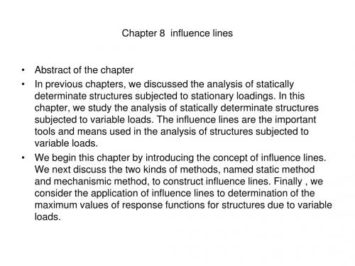
• It is important to realize that the ordinate of the influence line at any position x is equal to the magnitude of RB due to a unit load acting at the position x on the beam. • Generally, a graph indicating the variation of a response function such as one of reactions or internal forces of a structure, across which a downward unit load is moving, is termed as an influence line. For the graph, the position of the unit load, x, is abscissa, the value of the response function is ordinate. When constructing an influence line, the base line represents the possible moving range of the unit concentrated load, and the positive value of the influence line is depicted on the upper side of the base line and vice versa. The dimension of the ordinate is equal to the dimension of the response function divide by the dimension of the unit load.
- 1、下载文档前请自行甄别文档内容的完整性,平台不提供额外的编辑、内容补充、找答案等附加服务。
- 2、"仅部分预览"的文档,不可在线预览部分如存在完整性等问题,可反馈申请退款(可完整预览的文档不适用该条件!)。
- 3、如文档侵犯您的权益,请联系客服反馈,我们会尽快为您处理(人工客服工作时间:9:00-18:30)。
4 EI 2 EI 6 EI M AB A B 2 D AB M AB F l l l 2 EI 4 EI 6 EI M BA A B 2 D AB M BA F l l l
Slope-Deflection Equations: General (2) 线刚度 i EI
A rigid joint provides unknown reactive couple, which may be incurred by given angular displacement of that joint. (angular displacement → reactive couple) A hinged joint undergoes unknown angular displacement, which may be incurred by applied couple at that joint. (applied couple→ angular displacement)
One end of a member is supported by a pin or roller at its far end The angular displacement at the pin-supported end is not primary unknown, and does not have to be determined ΔA A’ l EI is constant A
M AB Pab
2 2
M BA
P A
l Pa 2b
VAB
l2
VBA
Pb 2 3 (l 2a) l Pa 2 3 (l 2b) l
A V
(A: Near end B: Far end) (B: Near end A: Far end)
B
B
P A MAB<0
M
P B MBA>0 A VAB>0
An Example
Assume an angular displacement q Fixed end moments given q
D EI A EI,l l E
EI M EA 4 q l EI M EB M ED 4 q l EI Pl M EC 4 q l 8
P
பைடு நூலகம்
Slope-deflection equation is the most general relation, which is independent of end supports A member with independent disp. at both ends is the most general (fundamental) working element in the disp. method For convenience of manual computation, three other specific elements are developed as our working elements
Neglecting axial deformation P X1 X2
Primary Structure
l/2
l/2
Fixed End Moment of Bending Members (2)
Pab2 l
2
Pa 2b l2
Pb2 l
3
( l 2a )
A a l b
B
A
Pa 2 l3
B
( l 2b )
P 1
2
3
The added link implies the existing of linear displacement
Identification of Unknown Displacements (3)
Slope-Deflection Equations: General (1)
The displacement method is also called slope-deflection method since it relates the unknown slopes and deflections to the applied load on a structure
Example 1:
Unknowns: θ B Disassemble into members Fixed-end moments
F M BA 4iq B M BA 4iq B 15
20kN A B
2kN/m C
3m 3m
6m
M BC ?
Pin-Supported End Span
M
V
Sign Convention:
FEM: Positive when it acts clockwise on the span FES: Positive when it causes the span rotate clockwise
Fixed End Moment of Bending Members (3)
Chapter 8
the Displacement Method
1
Fixed End Moment of Bending Members (1)
Under concentrated forces
a A
P
b B l
a
P
b
EI
SI to the 2nd degree
SI to the 3rd degree
A EI, l
A
B φB
DAB
M
B
M AB M BA
4 EI 2 EI 6 EI A B 2 D AB l l l 2 EI 4 EI 6 EI A B 2 D AB l l l
Difference between a rigid joint and a hinge connection
EI,l
C
EI l 4iq 4iq E 4iq Pl/8 4iq B
Joint Equilibrium
q=
Pl2
/ (128EI)
A
MEA
E
8
An Example-continued
Fixed end moments
D
EI Pl M EA M EB M ED 4 q l 32 EI Pl 3Pl M EC 4 q l 8 32 EI Pl M AE M BE M DE 2 q l 64 EI Pl 9 Pl M CE 2 q l 8 64
ql 2 12
M AB
Pab2 l2
ql 2 12
A
ql 2 8
B
M
Refer to 《结构力学》page 281~283 for FEMs for other loadings
Fixed End Moment of Bending Members (5)
Under support movements
A A
B
D
D1C R1i C1i B A , D 2C
C
lA lB R2i C2i D AB 2 2
B
Fixed End Moment of Bending Members (6)
φA
To produce a unit slope at joint B, how large a couple should be applied?
Identification of Unknown Displacements (1)
Kinematically indeterminate degree The number of unknown displacements occurring at the nodes (joints) of the structure is referred to as the degree in which the structure is kinmatically indeterminate
q = Pl2 / (128EI)
A E P C
B
9
The Displacement Method
When analyzing any indeterminate structures, it is necessary to satisfy equilibrium, compatibility, and force-displacement requirements.
P 1
2
3
θ1
1
θ2
2
θ3
3
Δ3
Neglecting axial deformation
Nodal Disp.:θ1 ,θ2 ,θ3 ,Δ3
Identification of Unknown Displacements (2)
The unknown nodal displacement is classified into angular displacement and linear displacement Each rigid joint has a angular displacement (2 dimensions) Neglecting axial deformation, the linear displacement can be recognized by replacing all rigid joint by hinge connections
l
ΔA A’ A φA φB l