XRNP1熔断器说明书
2021年3月版1 4英寸x1-1 4英寸(6mm x 32mm)高压熔断器块说明说明书
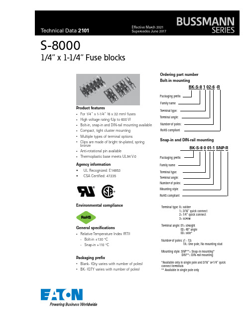
Product features• For 1/4” x 1-1/4” (6 x 32 mm) fuses • High voltage rating (Up to 600 V)• Bolt-in, snap-in and DIN-rail mounting available • Compact, tight cluster mounting • Multiple types of terminal options •Clips are made of bright tin-plated, spring bronze• Anti-rotational pin available•Thermoplastic base meets UL94 V-0S-80001/4” x 1-1/4” Fuse blocksBK-S-8 1 02-6 -RPackaging prefix Family nameTerminal type:Ordering part number Environmental compliancePackaging prefix• Blank- (Qty varies with number of poles)•BK- (QTY varies with number of poles)Terminal angle: Number of poles: RoHS compliantAgency information• UL Recognized: E14853•CSA Certified: 47235BK-S-8 0 01-1 SNP-RTerminal type: 0= solder1= 3/16” quick connect 2= 1/4” quick connect 3= screw Terminal angle: 01= straight 02= 40° angle 03= side*Number of poles: (1 - 12)1X= One pole, No mounting stud Mounting style: SNP**= Snap-in mounting* DIN**= DIN-rail mounting*Available only in single pole and 3/16” or 1/4” quick connect terminals** Available in single pole onlyFamily name Terminal type: Number of poles: RoHS compliantBolt-in mountingSnap-in and DIN-rail mountingPackaging prefix Terminal angle: Mounting style:General specifications•Relative Temperature Index (RTI)• Bolt-in +130 °C•Snap-in +110 °C2Technical Data 2101Effective March 2021S-80001/4” x 1-1/4” Fuse blocks/electronicsSpecificationsFamilyUL voltage rating (V)UL current rating (A)CSA voltage rating (V)CSA current rating (A)S-80006003030021S-81006002030013S-82006003030016S-83006003030025Straight 40°Angle terminalterminal Side Mountingterminal Straight 40°Angle terminalterminalScrew terminal Side MountingterminalS-8000 Single pole bolt-in mountingDimensions- mm/inchesS-8000 Single pole snap-in mountingMultiple poleoleNumber of polesA (inches)B (inches)A (mm)B (mm)1----2 1 1/8”5/8”28.615.93 1 3/4” 1 1/4”44.431.84 2 3/8” 1 7/8”60.347.653” 2 1/2”76.263.56 3 5/8” 3 1/8”92.179.47 4 1/4” 3 3/4”10895.28 4 7/8” 4 3/8”123.8111.19 5 1/2”5”139.712710 6 1/8” 5 5/8”155.6142.911 6 3/4” 6 1/4”171.4158.8127 3/8”6 7/8”187.3174.6Mounting dimensionsEatonElectronics Division 1000 Eaton Boulevard Cleveland, OH 44122United States/electronics © 2021 EatonAll Rights Reserved Printed in USAPublication No. 2101 March 2021Technical Data 2101Effective March 2021S-80001/4” x 1-1/4” Fuse blocks Life Support Policy: Eaton does not authorize the use of any of its products for use in life support devices or systems without the express writtenapproval of an officer of the Company. Life support systems are devices which support or sustain life, and whose failure to perform, when properly used in accordance with instructions for use provided in the labeling, can be reasonably expected to result in significant injury to the user.Eaton reserves the right, without notice, to change design or construction of any products and to discontinue or limit distribution of any products. Eaton also reserves the right to change or update, without notice, any technical information contained in this bulletin.Eaton is a registered trademark.All other trademarks are property of their respective owners.Follow us on social media to get thelatest product and support information.BPart number A (inches) B (inches) C (inches) A (mm) B (mm) C (mm)BK-S-8002-1X-DIN 20.5 1.3150.812.733.3BK-S-8102-1X-DIN 20.5 1.3150.812.733.7BK-S-8202-1X-DIN 20.5 1.3150.812.733.3BK-S-8301-1X-DIN 2.1890.5 1.3155.612.733.3BK-S-8103-1X-DIN 1.6930.953 1.314324.233.3BK-S-8203-1X-DIN1.6930.9531.314324.233.3DIN-rail mounting。
柯尼拜熔断器类型X和KS熔断器熔链电流等级说明说明书

Kearney Types X and KS Fuse Link RatingsAll fuse ratings 5.5 A and less are type X fuse links. All fuse ratings 7, 10, and 15 A are type X or type KS fuse links. All fuse ratings 20 A and larger are type KS fuse links.Fuse link ratings recommended in these tables will carry the full load of thetransformer continuously and will open in five minutes when the transformer load is approximately three times full load. Smaller or larger fuse link ratings may be used to give the desired correlation of protection and continuity of service. These tables are to be used as a guide until a more detailed study can be made by the user.Example for Chart 1This is the voltage supplied to the primary of the transformer. For example, if a 75 kVA transformer is connected between one-phase and neutral of a 13.2/22.9 kV three-phase system, the single-phase voltage is 13.2 kV . For an open Delta system where the voltage between phases is 22.9 kV , the single-phase voltage is 22.9 kV .Example for Chart 2If a 75 kVA three-phase transformer is made up of three 25 kVA single-phase transformers connected in closed delta to a 22.9 kV three-phase system, the three-phase voltage on the card would be 22.9 kV .Cooper Type D Fuse LinksType D Fuse Links are available in ratings of 1 through 20 A. Fuse link ratings r ec -ommended in these tables will carry the full load of the transformer continuously and will open within five minutes when the transformer load is approximately three times the full load current. Smaller or larger fuse link ratings may be used to give the desired correlation of protection and continuity of service. These tables are meant to be used as a guide until a more detailed study can be made by the user.Single-Phase TableThe Single-Phase Table is used for all single-phase, three-phase “WYE”, and outside legs of open delta connected transformers. Do not fuse the neutral on “WYE” and open Delta connected transformers.Three-Phase TableThe Three-Phase Table is used for closed delta and common legs of open Delta connected transformers. Use the fuse size recommended for the largest transformer connected to the lead under consideration. Refer to the single-phase table for “WYE” and open Delta connected transformers.Cooper Type D Fuse Link Ratings for Three-PhaseIndividual Transformer SizesKva SINGLE-PHASE VOLTAGE (Kv)2.4 4.87.27.627.971213.213.814.416.319.922.9553 1.5 1.5 1.511-----101054443 1.5 1.5 1.5 1.5111515755544333 1.5 1.525-151077555544437.5-20151515777755550--2015151010101077575-----1515151515107100-----20202020151515167----------2020250------------333------------500------------Transformer fusing tables for power line construction and maintenance© 2017 EatonAll Rights Reserved Printed in USAPublication No. MZ132005ENSupersedes July 2010 (B100-02022)November 2017Eaton1000 Eaton Boulevard Cleveland, OH 44122United States Eaton’s Power Systems Division2300 Badger Drive Waukesha, WI 53188United States/cooperpowerseriesEaton is a registered trademark.All other trademarks are property of their respective owners.COOPER POWERSERIESType K, T, 200, & QA Fuse LinksFuse link ratings recommended in these tables will carry the full load of thetransformer continuously and will open in five minutes when the transformer load is approximately three times full load. Smaller or larger fuse link ratings may be used to give the desired correlation of protection and continuity of service, These tables are to be used as a guide until a more detailed study can be made by the user.Single-Phase Table The single-phase table is used for all single-phase, three-phase “WYE” and outside legs of open delta connected transformers. Do not fuse the neutral.Three-Phase TableThe three-phase table is used for closed Delta and common legs of open Delta connected transformers. Use the fuse size recommended for the largesttransformer connected to lead under consideration. Refer to the single-phase table for “WYE” and open Delta connected transformers.Kearney Type K or T Fuse Link Ratings for Single-Phase Transformer Installations Three-Phase “WYE” and Outside Legs of Open DeltaKearney Type K or T Fuse Link Ratings for Three-Phase Individual Transformer Sizes In Closed Delta and Common Legs of Open DeltaKearney Type 200 Fuse Link Ratings for Single-Phase TransformerInstallations Three-Phase “WYE” and Outside Legs of Open DeltaKearney Type 200 Fuse Link Ratings for Three-Phase Individual Transformer Sizes In Closed Delta and Common Legs of Open DeltaType QA Fuse Link Ratings for Single-Phase TransformerInstallation, Three-Phase “WYE” and Outside Legs of Open DeltaType QA Fuse Link Ratings for Three-Phase Individual TransformerSizes In Closed Delta and Common Legs of Open DeltaKva RA TED LINE VOLTAGE (kV)2.4 4.16 4.87.27.621213.213.814.422.932111111111532211111117.56322111111106332211111158663322221251588663333237.5251210886333350301515101066663755025251515888861006530302020121010106150100505030302015151510167100655030302020201510200140656540402520202012250140808050503025252515333140100100656540404030205002001401401001006550505030Kva RA TED LINE VOLTAGE (kV)2.4 4.16 4.87.28.321212.4713.213.814.422.93322111111115633221111117.5863322211111010663322222115158866333332252515128666633337.5402520121018106663505030251515101010886758050402525151515121281001006550303020202015151015014010080505030303025251516714010080655030303030302020020010010065654040403030202502001401008080505050404025333200140140100100656565656540500-200200140140100100100808050Kva RA TED LINE VOLTAGE (kV)2.4 4.16 4.87.27.621213.213.814.422.932111111111532211111117.553221111111073322111111510553322221251577553333237.52515107755553503015151010755537550252515151077751006530302020151010107150100505030302015151510167100655030302020201510200125656540402520202015250150808050503025252515333175125100656540404030205002001751501001006550505030Kva RA TED LINE VOLTAGE (kV)2.4 4.16 4.87.28.321212.4713.213.814.422.93322111111115533221111117.57553222111110107533222221151510755333332252515157755555337.54025201510777775505030251515101010775758050402525151515151571001006550303020202015151015015010080505030303025251516717510080655030303030302020020012510065654040403030202502001501258080505050404025333-175175125100656565656540500-200200175150100100100808050Kva SINGLE-PHASE VOLTAGE (Kv)2.4 4.87.27.627.971213.213.814.416.319.922.934.45321111111111110103222111111111557333222211112525107773333222137.54020101010775533325050251515151077775327575402525251510101010773100100503030302020151515101071671507550505030302525252020102502001257575755040404030302520333-1501001001006060505050403025500-20015015015010075757575605030Kva*RA TED LINE VOLTAGE (kV)2.4 4.16 4.87.21213.213.822.934.4573321111110151075222111525151073332125402520107773237.560403020101010735075504025151515757512575604025252510710015010075503030302010167-1501251005050503020250-2001751257575754030333---1751001001006040500----1501501507560* Single-phase kVA of three-phase bank。
电能中高压熔断器说明书

18Medium Voltage FusesMedium Voltage Fuses18 Medium Voltage FusesProduct Description . . . . . . . . . . . . . . . . . . . . . . . . . . . . . . . . . . . . . . V12-T18-2Product History . . . . . . . . . . . . . . . . . . . . . . . . . . . . . . . . . . . . . . . . . . V12-T18-2Product History Time Line. . . . . . . . . . . . . . . . . . . . . . . . . . . . . . . . . . V12-T18-2Product Application and Naming. . . . . . . . . . . . . . . . . . . . . . . . . . . . . V12-T18-3Current-Limiting Fuses . . . . . . . . . . . . . . . . . . . . . . . . . . . . . . . . . . . . V12-T18-4Expulsion Fuses. . . . . . . . . . . . . . . . . . . . . . . . . . . . . . . . . . . . . . . . . . V12-T18-5Product Selection . . . . . . . . . . . . . . . . . . . . . . . . . . . . . . . . . . . . . . . . V12-T18-6Further Information . . . . . . . . . . . . . . . . . . . . . . . . . . . . . . . . . . . . . . . V12-T18-8Pricing Information . . . . . . . . . . . . . . . . . . . . . . . . . . . . . . . . . . . . . . .V12-T18-81818Medium Voltage FusesCurrent-Limiting and Expulsion FusesCurrent-Limiting andExpulsion FusesOriginally aWestinghouse ProductMedium Voltage FusesProduct DescriptionEaton medium voltagefuses offer such a range ofcharacteristics that almostany fuse application, withinthe practical range of suchinterrupting devices, maybe satisfied. This range ofcharacteristics is offeredin part by the production ofboth expulsion and current-limiting power fuses.Expulsion and current-limitingfuses provide such diversecharacteristics by employingdifferent areas of fusetechnology. These differencesin technology, along with thediverse characteristics, requirethat different questions beanswered when applyingexpulsion and current-limiting fuses.Product HistoryThe Eaton power fuse productline was introduced in the1930s by WestinghouseElectric Corporation. As powersystems grew in size, the needto sectionalize utility feedersand to protect equipmentbecame apparent. The initialfuse development effortsresulted in the creation ofnon-current-limiting, expulsiontype fuses. As the availablefault currents grew, the needfor a current-limiting fuse wasapparent and this resulted innew interruption techniques.While basic fuse technologyhas not changed greatlyover the years, gradualimprovements have beenmade to make the fusesmore current-limiting andeasier to manufacture andinstall. Because standardsfor fuses (ANSI C37) detailonly test methods and basicperformance requirements,many different varieties offuses (length, diameter, short-circuit interruption curves)have been introduced overthe years.Eaton presently manufacturesmedium voltage fuses inHaina, DR.Product History Time LineFuses in PerspectiveAdvantagesMedium Voltage Fuse ComparisonNotes1BAL superseded by CLE.2BAL-R superseded by CLS.3BA—Refills and holders only, new installations use RBA.4DBA—Refills only.5DBS—Superseded by DBU.VoltageTypeClassApplicationAmp RatingExpulsion Current-LimitingVented SealedElectromechanical StaticExpels gases/noise No gases/noiseInterrupts at natural current zero Limits fault currentGenerally higher voltage/current applications Generally higher interrupting ratingsDifferences in time/current characteristics Differences in time/current characteristics1818Medium Voltage FusesCurrent-Limiting and Expulsion FusesApplication GuideGuide to NamesBCLS—Bolt-in version of CLS fuse .BHLE—Bolt-in version of HLE fuse.CLE —Current-limiting E-rated.HLE/HCL —Current-limiting E-rated, interchangeable with General Electric and Gould Shawmut.CX/CXN —Current-limiting interchangeable with McGraw-Edison’s NX brand fuses, C-rated.CLT —Current-limiting transformer fuse.CLPT —Current-limiting E-rated for potential transformers.CLS —Current-limiting for motor starters, R-rated.RBA —Refillable boric acid expulsion fuse (indoor use).RDB —Refillable dropout boric acid expulsion fuse (outdoor use).DBU —Dropout boric acid fuse interchangeable with S&C’s SMU-20 refill.Guide to Ampere Ratings“E” DesignationFuse rated 100E or below will melt in 300 seconds at a current value between 2.0 and 2.4 times the E number.Fuse rated above 100E will melt in 600 seconds at a current value between 2.2 and 2.64 times the E number.If the current is higher than 2.4 or 2.64 times the E number, the user must consult the time-currentcurves for that particular fuse.“R” DesignationThe fuse will melt in 15 to 35 seconds when the current equals 100 times the R number.If the current is higher than 100 times the R number, the user must consult the time-current curves for that fuse.“C” DesignationThe fuse will melt in1000 seconds at a current value, between 1.7 and 2.4 times the C number.If the current is higher than 2.4 times the C number, the user must consult the time-current curves for that particular fuse.“A” DesignationFuses that do not comply with “E,” “R” or “C” designations.Expulsion fuses can also be E-rated, K-rated and T-rated, and are also covered in the ANSI standards. The K and T ratings refer, respectively, to relatively “fast” and “slow” melting expulsion fuses. Detailed time-current tables adequately define these ratings.Selection GuideRatingsFeeder Circuit Section-alizing Fused Switches Power Trans-formersSubstationService Trans-formers DIP Pole Underground DistributionTransformersPole-MountedTrans-formers Pad-Mounted Distribution Transformers Motor Starters Potential Trans-formers Sub-stationCapacitorBanksType Class UseBrand kV,Ampere,kACurrent limitingGeneral purposePower BHLE/CLE/HLE/HCL 2.4–15.5 kV 10E–1350A to 85 kA ■■■■■Dist.CX/CXN 4.3–15.5 kV 3.5C–300C 50 kA ■■CLT2.4–15.5 kV 4A–150A 25 kA ■Backup Power CLPT2.4–38 kV 0.25E–10E to 80 kA ■Power BCLS/CLS2.4–8.3 kV 2R–36R 50 kA ■ExpulsionBoric acidPower RBA4.8–34.5 kV 0.5E–720E ■■■■RDB 4.8–34.5 kV 0.5E–720E ■■■■■■DBU14.4–38 kV 5E–200E 15SE–200SE 3K–200K■■■■■■1818Medium Voltage FusesCurrent-Limiting FusesCurrent-Limiting FusesCLE and HLE Current-Limiting—E-RatedCLPT Current-Limiting E-Rated forPotential Transformer ProtectionCLS Current-Limiting for Motor StarterCX Current-Limiting—Interchangeablewith McGraw Edison’s NX TypeCLT Current-Limitingfor Transformer ProtectionProduct DescriptionCurrent-limiting fuses areconstructed with pure silverfuse elements, a high-puritysilica sand filler, a speciallydesigned core and a glassresin outer casing.A high fault current melts thesilver element almost instantlyand loses energy to thesurrounding sand. The sandmelts and forms fulgurite,a glass-like substance.The arc voltage rapidlyincreases to nearly threetimes the fuse voltage ratingand forces the current tozero. Low fault current meltsa solder drop on the silverfuse element that, in turn,melts the silver.The element burns back untilthere is a sufficient internalgap to interrupt the current.This is known as the M-effect.Eaton current-limiting fusesare offered in two basictypes: backup and generalpurpose. Backup fuseshave a published minimuminterrupting current andrequire a series device forbreaking the circuit forcurrents below this minimumlevel. General purpose fuseshave improved low currentinterruption capability and aredesigned to interrupt low faultcurrents that cause the fuse tomelt in one hour or less.General InformationApplicationsCurrent-limiting technologiescan be used to meet almostevery fuse application. Typicalapplications for utility,industrial, construction andOEM customers include:●Feeder circuitsectionalizing●Power transformers●Substation servicetransformers●Underground distributiontransformers●Pole-mountedtransformers●Pad-mounted distributiontransformers●Fused switches●DIP poles●Motor starters●Potential transformers●Substation capacitor banksAccessoriesA wide assortment ofmountings, live parts andend fittings are availableto facilitate power fuseinstallation.Mountings include a base,porcelain or glass polyesterinsulators and live parts. Theyhelp enable the fuse to besafely attached to the gear.Mountings can be eitherdisconnect or nondisconnect.Live Parts attach the fuseto the mountings and areconsidered part of themounting. All parts abovethe insulators are live parts.Live PartsEnd Fittings are metal partsthat attach to each end ofthe fuse at the ferrules.They are used only ondisconnect fuses or whenconverting a nondisconnectto a disconnect fuse.1818Medium Voltage FusesExpulsion FusesExpulsion FusesRBA—Refillable Boric AcidRDB—Refillable Dropout Boric AcidDBU—Dropout Boric Acid—Interchangeable with S&C’s SMU-20Product DescriptionEaton expulsion fuses use boric acid as theinterrupting medium. Under a fault condition, arc heat decomposes the boric acid, which produces gases and boric anhydride. The water vapor blast extinguishes the arc in a deionizing action and exits from the bottom of the fuse.Type RBA indoor expulsion fuses are fitted with a filter or condenser that moderates the discharge exhaust. The discharge filter limits the exhaust to a small and relatively inert amount of gas and lowers the noise level without affecting the fuse interrupting rating. Steam discharge, that can affect the interrupting, is fully restricted by the condenser.Each type RDB outdoor dropout fuse includes an ejector pin that is forced through the top of the fuse. The ejector pin releases a latch on the mounting and the fuseholder is kicked outward and swings into the dropout position, through 180° with a vertical mounting, or 90° with an underslug mounting.Refill units can be fieldinstalled into RBA and RDB expulsion fuses. Once the old unit has been removed, the separately purchased unit can be easily installed into the fuse holder.General InformationApplicationsExpulsion technologies can be used to meet a number of fuse applications. Typical applications for utility, industrial construction and OEM customers include:●Feeder circuit sectionalizing ●Fused switches ●Power transformers ●Substation service transformers ●DIP poles●Potential transformers●Substation capacitor banksAccessoriesThe following accessories are available for expulsion fuses:Mountings include a base, porcelain or glass polyester insulators and live parts. They help enable the fuse to be safely attached to the gear. Mountings can be either disconnect, nondisconnect or dropout. Fuses may be vertical or underhung.Live Parts attach the fuse to the mountings and are considered part of the mounting. All parts above the insulators are live parts.End Fittings must bemounted on DBU fuse units to enable them to be fitted into the mounting.Filters and Condensers are for indoor applications of RBA expulsion fuses. They confine the arc within the fuse and substantially reduce the noise and exhaust when the fuse interrupts.Mufflers are used with DBU fuses in indoor applications to virtually eliminate offensive noise and exhaust gases when the fuse interrupts.18Medium Voltage FusesCurrent-Limiting and Expulsion FusesProduct SelectionEasy to Use, Easy to Order! Eaton’s fuse catalog numbering system makesit easy to order the right fuse. The catalog numbers are easy to remember, unique to each fuse, andare broken down in three descriptive segments: fuse type, voltage rating and current rating.These catalog numberscan be entered directlyand easily:●No change in orderprocessing will occur if you use either a style numberor its correspondingcatalog number. Y ouwill get the same fuse●In the back of this orderingguide is a style numberto catalog number cross-reference chartCurrent-Limiting Fuse Examples●5CLE-30E5.5 max. kV, CLE fuse unit,30E amperes●15CXN-45C15.5 max. kV, CXN fuseunit, 45C amperes●5CLS-GDM-E5.5 max. kV, CLS fuseunit, glass polyesternondisconnect mounting ●CLE-DL-DCLE, disconnect liveparts, size D Catalog Numbering SystemCurrent-Limiting FusesCurrent-Limiting Fuse AccessoriesAmperes0.5–1350SizeABDClassERCXMaximum kV2 =(2.4, 2.5, 2.75)4 =(4.3, 4.8)5 =(5.08, 5.5)7=(7.2)8=(8.3)15 =(15.5)25 =(25.5)38 =(38.0)TypeCLEHLEBHLECLPTNCLPTCLSBCLSCLS70CLS75HCLSLCLSCXCXNCLTAHLEACLS15CLE–100E–(D)InsulatorG=Glass polyesterP=PorcelainH=High BILDiameter SizeA=1-5/8 inches (41.3 mm)0.5E–1.5E single barrelB=1-5/8 inches (41.3 mm)3E–10E single barrelC=2.00-inch (50.8 mm)single barrelD=3.00-inch (76.2 mm)single barrelE=3.00-inch (76.2 mm)double barrelF=4.00-inch (101.6 mm)double barrelG=5/8-inch (15.9 mm)ferrule (CX/CXN only)HardwareDM=Disconnect mountingNM=Nondisconnect mountingDL=Disconnect live partsNL=Nondisconnect live partsDF=Disconnect end fittingsTypeCLEHLECLPTNCLPTCLSHCLSLCLSCXCXNCLTMaximum kV2 =(2.4, 2.5, 2.75)4 =(4.3, 4.8)5 =(5.08, 5.5)7=(7.2)8=(8.3)15 =(15.5)25 =(25.5)38 =(38.0)15CLE–P NM–(C)1818 Medium Voltage FusesCurrent-Limiting and Expulsion FusesProduct Selection Expulsion Fuse Examples●8RBA2-10E8.3 max. kV, RBA-200 refill,10E amperes●DBU17-30K17.1 max. kV, DBU fuseunit, 30 amperes●15RBA8-INH15.5 max. kV,RBA-800, indicatingnondisconnect holder●RBA4-FLTRRBA-400 filter Catalog Numbering SystemExpulsion Fuse UnitsExpulsion Fuse AccessoriesNote1Maximum kV occurs after DBU or before BA, DBA, RBA, RBT or RDB.DBU17–100EAmperes0.53567810121520253040506580100125140150175200250300400SpeedEKSETypeRBADBUDBARBTBAMaximum kV 181517252738487292121145InsulatorG=GlasspolyesterP=PorcelainHP=High LIWLporcelainBolt-InB=1-5/8 inches (41.3 mm),3E–10E, single barrelHardwareUM=Underhung mountingDL=Disconnect live partsNL=Nondisconnectlive partsDH=Disconnect holderNH=Nondisconnect holderNM=NondisconnectmountingUL=Underhung live partsVL=Vertical live partsI=IndicatingFLTR=FilterCOND=CondenserMFLR=MufflerSHNT=Shunt and springassemblyTypeRBADBURDBBAMaximum kV 18151725273815RBA2–P NM–(B)181818Medium Voltage FusesCurrent-Limiting and Expulsion FusesFurther InformationPricing InformationPrice and Availability Digest (PAD)Vista/VISTALINE™ Discount Symbols Y1-F, Y1-FE, Y1-FHPublication NumberDescriptionCurrent-Limiting Fuses CA08100016EFuse Catalog, Volume 14, Tab 3Expulsion Fuses CA08100016EFuse Catalog, Volume 14, Tab 2General Information CA08100016EFuse Catalog, Volume 14。
欧普斯莫尔恩熔断器启动切断开关操作和维护手册说明书

O p e r at i O n a n dM a i n t e n a n c e M a n ua lf u s i b l es h u n t t r i p sw i tc h2 • Fusible Shunt Trip SwitchENCLOSED INDUSTRIAL CONTROL PANELFusible Shunt Trip SwitchDevice Overview . . . . . . . . . . . . . . . . . . . . . . . . . . . . . . . . . . . . . . . . . . . . . . . . . . . . . . . . . . . . . . . . . . . . . . . . . . . . . .2Installation Instructions . . . . . . . . . . . . . . . . . . . . . . . . . . . . . . . . . . . . . . . . . . . . . . . . . . . . . . . . . . . . . . . . . . . . . . . .3Catalog Number Selection T able . . . . . . . . . . . . . . . . . . . . . . . . . . . . . . . . . . . . . . . . . . . . . . . . . . . . . . . . . . . . . . . .4Motor Fuse Selection T able . . . . . . . . . . . . . . . . . . . . . . . . . . . . . . . . . . . . . . . . . . . . . . . . . . . . . . . . . . . . . . . . . . . . .5Wiring Diagram – 120VAC Control Interface . . . . . . . . . . . . . . . . . . . . . . . . . . . . . . . . . . . . . . . . . . . . . . . . . . . . . .6Wiring Diagram – 24V (AC or DC) Control Interface . . . . . . . . . . . . . . . . . . . . . . . . . . . . . . . . . . . . . . . . . . . . . .7T orque Specifications . . . . . . . . . . . . . . . . . . . . . . . . . . . . . . . . . . . . . . . . . . . . . . . . . . . . . . . . . . . . . . . . . . . . . . . . . .8Maintenance . . . . . . . . . . . . . . . . . . . . . . . . . . . . . . . . . . . . . . . . . . . . . . . . . . . . . . . . . . . . . . . . . . . . . . . . . . . . . . . . . .9Warranty . . . . . . . . . . . . . . . . . . . . . . . . . . . . . . . . . . . . . . . . . . . . . . . . . . . . . . . . . . . . . . . . . . . . . . . . . . . . . . . . . . . . .9FAQs (Frequently Asked Questions) . . . . . . . . . . . . . . . . . . . . . . . . . . . . . . . . . . . . . . . . . . . . . . . . . . . . . . . . . . . .9Spare Parts List . . . . . . . . . . . . . . . . . . . . . . . . . . . . . . . . . . . . . . . . . . . . . . . . . . . . . . . . . . . . . . . . . . . . . . . . . . . . . . .10D e V I C e O V e r V I e WFusible shunt trip disconnect switches are a required safety feature in many industrial and commercial applications. Main branch-circuit fuses provide overcurrent protection in the event of short-circuits, power surges, damage to electrical wiring, etc…by interrupting faulty circuitry and removing it from the electrical system. In addition, the molded case switch can disconnect power from the source prior to known electrical disturbances, before the fuse is required to operate. Integrated into the molded case switch is an electromagnet (shunt trip coil), controlling a spring-loaded conductivestrip which maintains continuity between the line side and load side terminals of the switch. The electromagnetic coil is normally connected to a safety system, such as a fire alarm or smoke detector housed in the surrounding building. Should there be an electrical emergency, a signal is sent to the coil (via the safety system, alarm, sprinkler, etc…) and the electromagnet would be engaged, throwing the switch and disconnecting power. Power can only then be reenergized by manually operating the molded case switch. • Fusible Shunt Trip Switch 3D A N g e r A N D WA r N I N g L A b e L SU L L I S T I N g I N F O r M AT I O NStep 1: Disconnect power from the circuit where the fusible shunt trip switch will be installed. Mount the panel. Wire up the line side three phase conductors into the three line side terminals of the molded case switch (L1, L2 and L3). Wire the load side to the three load side terminals of the class J fuseholder (T1, T2 and T3).Step 2: Wire the remote control elements to the specified terminal blocks shown in the wiring diagrams on page 6 and 7 (120VAC and 24VAC/DC respectively) of this manual. For 120VAC, safety system controls must supply a set of dry (no voltage) contacts. For 24VAC/DC, safety system controls must provide the voltage source.Step 3: Connect power to the circuit on which the fusible shunt trip disconnect switch is installed. T est the shunt trip operation. Close the molded case switch manually; the pilot light (if installed) indicating that the switch is closed will indicate. engage the key switch (if installed) to activate the shunt trip and trip the molded case switch. The switch will trip and the pilot lightwill turn off.e S S e r I e S–F U S I b L e S h U N T T r I P D I S C O N N e C T S W I T C hFire Alarm Voltage Monitoring relay included in all Mersen offerings. No additional part suffixes required. (Competitor Options F1 and F3)*Neutral lug rating should be greater than or equal to the switch ampere rating. For 200% lug over sizing, select next higher rating. N4 is suitable for 200% over sizing at 400A. • Fusible Shunt Trip Switch • Fusible Shunt Trip Switch 5Minimum – This sizing is recommended if motor acceleration time does not exceed 2 seconds. Minimum sizing with class J fuses will provide overload relay back up protection but may not coordinate with some NeMA Class 20 overload relays. Minimum sizing is generally not heavy enough for motors with code letter g or higher.Typical – Suggested for most applications. Will coordinate with NeMA Class 20 overload relays. Suitable for motor acceleration times up to 5 secondsHeavy – Maximum allowable fuse size when an overload relay or motor thermal protector is included in the branch circuit. If this fuse size is not sufficient to start the load, class J time-delay fuses may be increased to a maximum of 225% of full load amperes. Suggested for Design e and high efficiency Design b motors.Notes:1. Tb-5 and Tb-9 must be dry (no voltage) normally open contacts from safety system2 . If a surge protection option is selected, it will be corrected line to ground between the STS and fuses F1-F3 • Fusible Shunt Trip Switch • Fusible Shunt Trip Switch 7Notes: 1.For 24VAC control systems, 24VAC must be connected between Tb-5 and Tb-3. For 24VDC control systems, 24VDC must be connected between Tb-5 and Tb-3. Do not source AC voltage into a DC control system or vice versa.2 .If a surge protection option is selected, it will be connected line to ground, between the STS and fuses F1-F3. • Fusible Shunt Trip Switch • Fusible Shunt Trip Switch 9M A I N T e N A N C eThe following preventative maintenance measures should be considered in order to maintain product integrity •Periodically clean product exterior and interior to remove any dust, particles, tools or other. Follow proper safety precautions when performing maintenance.•Periodically check lug torque values in order to maintain product specifications. recommended torque values for all parts are shown on page 8 of this manual. Follow proper safety precautions when performing maintenance.•Preventative maintenance may include thermal-scan imaging in order to identify any “hot-spots” or generation of excessive heat. Any temperature increase, not related to load variations or ambient temperature could signal a problem with lug torque.•Maximum temperature at any lug should never exceed 75ºC under any conditions.WA r r A N T yMersen warrants to the buyer that products and any services furnished hereunder will be free of from defects in material, workmanship and will be of the kind and quality specified in Mersen standard terms and conditions. The foregoing shall apply only to failure to meet said warranties (excluding any defects in title), which appear within 1 year from the date of delivery to the customers site. All other non-Mersen manufactured components used in the fabrication of Mersen equipment shall be covered by their respective manufacturers’ warranties.10 • Fusible Shunt Trip SwitchQ: If I accidentally order the Fusible Shunt Trip Switch with a wrong component or my job parameters have changed, can the component be changed in the field?A:Unfortunately the answer is NO. T o comply with UL guidelines, product modifications can only be completed by authorized factory personnel. Other modifications will void the Mersen warranty and UL listing.Q:Are the units tested before they leave the factory?A: yeS. Mersen tests and documents every unit that leaves the factory floor. A shunt trip switch inspection report is included within every unit.Q: What is the shipping method and typical weights of a unit?A:All units are shipped on pallets via truck. Unit weight varies depending upon ampere rating from approximately 70 pounds up to 200 pounds each.Q:Why do the fuses on the control transformer keep opening?A: The safety system normally open contacts (connection between Tb-5 and Tb-9) are likely supplying voltage. Check to ensure that there is no voltage present.Q: Is there a technical support number I can call for assistance?A:yeS. Mersen offers live technical support from 8:00AM to 6:30PM eST. Call (978) 465-4853 for assistance, or email ********************************. • Fusible Shunt Trip Switch11。
XRNT熔断器使用说明书

基本参数
额定电压(KV)
熔断器额定电流(A)
熔断器额定电流(A)
额定熔断电流(KA)
12Байду номын сангаас
63
10、16、20、25、31.5、40、50、63
50
技术数据
型号
额定电压(KV)
额定电流(A)
直径(mm)
国外参考型号
XRNT□
12
12
76
FFLAJ
16
20
31.5
40
50
63
80
88
100
XRNT熔断器产品用途
XRNT熔断器适用于户内交流50Hz,额定电压12KV系统,它能够可靠地切断最小开段电流至额定开端电流之间的任何故障电流,产品不仅具备限流熔断器具有的较高分断能力,并且具备非限流式熔断器具有的较好的小电流保护特点,可获得全范围开断的良好保护特性。
XRNT熔断器产品型号
国际型号
等同的国外型号
XRNT-40.5KV熔断器使用说明书

丁字帽
XRNT
SFM.J
7.2
100 200 125 160
φ76×442
丁字帽
XRNT
SDL.J
12
6.3 10 12.5 16 20 25 31.5 40
φ51×292பைடு நூலகம்
丁字帽
XRNT
SFL.J
12
50 63 71 75 80 100 125
φ76×292
丁字帽
XRNT
SXL.J
12
XRNT-40.5KV熔断器参数
型号
额定电压(KV)
熔体额定电流(A)
熔管尺寸φ×C(mm)
备注
XRNT
SDL.J
7.2
6.3 10 16 20 25 31.5 40 50
φ51×292
丁字帽
XRNT
SFL.J
7.2
63 71 75 80 100 125
φ76×292
丁字帽
XRNT
SXL.J
7.2
160 200 250 315
φ51×442
丁字帽
XRNT
SFM.J
24
40-125
φ76×442
丁字帽
XRNT
SDQ.J
40.5
2 3.15 6.3 10 16
φ51×537
丁字帽
XRNT
SFQ.J
40.5
20 31.5 40
φ76×537
丁字帽
XRNT
SXQ.J
40.5
50 63
φ88×537
丁字帽
XRNT
SKY.J
40.5
产品用途
本产品适用于户内交流50Hz,额定电压3.6KV、7.2KV、12KV、24KV、40.5KV系统,可与其它开关电器如负荷开关,真空接触器配合使用,作为电力变压器及其它设备短路、过载的保护元件,又是高压开关框、环网框、高/低压预装式变电站必备的配套产品。
熔断器产品说明书
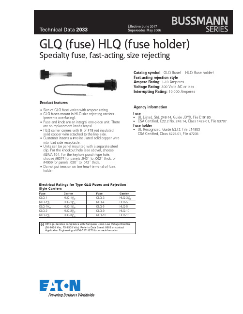
Product featuresAgency informationFuse•UL Listed, Std. 248-14, Guide JDYX, File E19180•CSA Certified, C22.2 No. 248.14, Class 1422-01, File 53787Fuse holder•UL Recognized, Guide IZLT2, File E14853CSA Certified, Class 6225-01, File 47235GLQ (fuse) HLQ (fuse holder)Specialty fuse, fast-acting, size rejecting•Size of GLQ fuse varies with ampere rating.•GLQ fuses mount in HLQ size rejecting carriers (prevents overfusing).•Fuse and knob are an integral one-piece unit. There are no replacement knobs (caps).•HLQ carrier comes with 6· of #18 red insulated solid copper wire attached to the line side.•Customer inserts a #18 insulated solid copper wire into load side receptacle.•Units can be panel mounted with a separate steel clip. For the knockout hole (see above), choose #BK/A-104. For the keyhole punch type hole,choose #6374 for panels .043” to .062” thick, or #4909 for panels .030” to .042” thick.•Do not put tension on line (rear) terminal of fuse-holder.Catalog symbol: GLQ (fuse) HLQ (fuse holder)Fast-acting rejection style Ampere Rating: 1-10 Amperes Voltage Rating: 300 Volts AC or less Interrupting Rating: 10,000 AmperesEatonElectronics Division 1000 Eaton Boulevard Cleveland, OH 44122United States/electronics © 2017 EatonAll Rights Reserved Printed in USAPublication No. 2033 SB02233 June 2017Eaton is a registered trademark.All other trademarks are property of their respective owners.Life Support Policy: Eaton does not authorize the use of any of its products for use in life support devices or systems without the express written approval of an officer of the Company. Life support systems are devices which support or sustain life, and whose failure to perform, when properly used in accordance with instructions for use provided in the labeling, can be reasonably expected to result in significant injury to the user.Eaton reserves the right, without notice, to change design or construction of any products and to discontinue or limit distribution of any products. Eaton also reserves the right to change or update, without notice, any technical information contained in this bulletin.GLQ (fuse) HLQ (fuse holder)Specialty fuse, fast-acting, size rejectingTechnical Data 2033Effective June 2017Dimensional DataFUSEKeyhole PunchKnockout Hole(15.9mm).1110100200CURRENT IN AMPERESAMPERE RATING51.5100101.1.01T I M E I N S E C O N D S151210Time-Current Characteristic Curves–Average Melt。
西熔户内熔断器技术说明
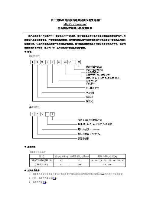
以下资料来自西安西电集团高压电瓷电器厂/全范围保护用高压限流熔断器本产品适用于户内交流50Hz,额定电压12kV的系统,作为变压器及其它电力设备过载或短路等保护元件,全范围保护用高压熔断器是一种新型的限流熔断器,它能够可靠的开断引起熔体熔化的电流至额定开断电流之间的任保故障电流,它是利用限流式熔断件具有较高分断能力,而非限流式熔断件却具有较好的小电流保护特点,结合两种熔断件的不同特点,组合为一体,获得全范围开断的良好保护特性。
◆型号:(1)国标型号(2)英国型号◆基本参数:熔断器的基本参数◆主要技术数据:1、熔断器在规定的使用条件下能可靠的分断使熔体熔化电流至额定开断电流为50kA之间的任何故障电流。
2、时间—电流特性曲线如图1。
3、限流特性如图2。
4、t特性如表:弧前t最小值(S)弧前t最大值(S)2.2× 4.7×3.4× 6.1×7.7× 1.1×1.3× 1.5×2.5× 2.5×3.8× 3.8×5.1× 5.4×6.8× 5.6×◆外型及安装尺寸:◇外型及安装尺寸图◆选用导则:用于保护12kV变压器的熔断件一般选用导则如表:变压器保护用高压限流熔断器——符合德国DIN标准外型尺寸的熔断器本产品适用于户内交流50Hz,额定电压12kV系统,并可与其它保护电器(如:负荷开关,真空接触器)配合使用,作为电力变压器及其它电力设备过载或短路等保护元件。
◆型号:(1)国标型号(2)英国型号◆基本参数:熔断器的基本参数注:(1) *号由是否安装撞击器确定(2) ()为英国型号◆主要技术数据:1、熔断器在规定的使用条件下,能可靠的分断最小开断电流为(2.5-3)倍熔断件额定电流Ie至额定开断电流为50kV之间的任何故障电流。
2、时间—电流特性曲线如图1,最小开断电流以上部分用虚线表示。
XRNT-24KV熔断器说明书

XRNT-24KV熔断器产品用途
XRNT-24KV熔断器适用于户内交流50Hz,额定电压3.6KV、7.2KV、12KV、24KV、40.5KV系统,可与其它开关电器如负荷开关,真空接触器配合使用,作为电力变压器及其它设备短路、过载的保护元件,又是高压开关框、环网框、高/低压预装式变电站必备的配套产品。
XRNT-24KV熔断器产品型号
国内型号
等同的国外型号
XRNT-24KV熔断器外型及安装尺寸
XRNT-24KV熔断器参数
1、10KV最大短路开断电流(开断能力)50KA(I1);40.5KV最大短路开断电流31.5KA(I2)
2、最小开断电流:
熔断器额定电流的4位(100A以下)含100A (I3)
熔断器额定电流的7位(125A以上)含125A (I3)
上海昌开电器有限公司。
XRG3-50 5-3P-SP 开关切断熔断器说明书

Certificates and Declarations (Document Number)
Declaration of Conformity - CE Instructions and Manria (BG)
1SEC313002D0201 9AKK107492A8857 9AKK107680A0402
600 mm
XRG3-50/5-3P-SP
Product Net Height Product Net Depth / Length Product Net Weight
PRODUCT-DETAILS
XRG3-50/5-3P-SP XRG3-50/5-3P-SP Switch disconnector fuse
General Information
Extended Product Type Product ID EAN Catalog Description Long Description
3 acc. to IEC 60529 Front IP41
Bolt NH No
Switching of motor loads or other highly inductive loads - frequent actuation (AC-23A)
Switching of mixed resistive and inductive loads, including moderate overloads - occasional actuation (AC-22B)
Environmental
RoHS Status
2
200 mm 335 mm
3.6-40.5kv高压限流熔断器

3.6-40.5kv高压限流熔断器
本产品适用于户内交流50Hz,额定
电压3.6-40.5kV系统作为电压互感器的
过载或短路保护之用,(通过国家高压电器
质量监督检测中心试验,产品符合
GB/T15166.2和IEC60282-1)。
1.型号
2.基本参数
熔断器的基本参数如表
3.主要技术数据
(1)熔断器在规定的使用条件下,能可靠的分断使熔体熔化的电流至额定开断电流50kA之间的仍何故障电流。
(3)时间--电流特性曲线如(图1)所示,最小开断电流以上部分为虚线。
(4)限流特性如(图2)。
4.外型及安装尺寸
熔断器的外型及安装尺寸如(图3)和表2所示
表2
订购该产品
RN系列高压交流熔断器
本系列高压交流熔断器适用于户内交流50Hz,额定电压3kV-35kV
电力系统,用于对电力线路、变压器、电压互感器及其它电器的过载及短
路保护,亦可用以保护电力系统分出的支路,当线路短路电流达到最大值
之前熔断器就将线路切断。
1.型号
2.基本参数
熔断器的基本参数如表
表一
-6
-10
-3
-6
-10
注:*号为双拼管
表二
-35
-35
-35
注:*号为双拼管
3.外型及安装尺寸
、型户内高压熔断器外形尺寸如(图1)、(图2)和表3所示
表三
、-10/2
、-10/75*
、-35/2
( )为RN,-6外形尺寸
型户内高压熔断器外形尺寸如(图3)、(图4)及表4
表四
-10
-35
订购该产品。
高压熔断器产品参考手册说明书

Product featuresUL® Recognized, Guide JDYX2, File E19180Fuse holder•UL Recognized, Guide IZLT2, File E14853 HLR-2A andG MW (fuse) HWA (fuse holder)Specialty fuse fast-acting and fuse holder•Can be soldered direct into circuit or can be mounted in HWA holder which can be soldered into circuit.•Transparent window in fuse for visual determination of open fuse element•Fuseholder body and knob material is diallyl phthalate •Holder includes “O”-ring, gasket, and nut•Type HWA-AF holder includes waterproof cap (knob) AF •Sub-miniature pin-base fuses for limited space applicationsCatalog symbol: GMW (fuse) H WA (fuse holder) Ampere Rating: 1/100 - 5 AVoltage Rating: 125 Volts AC or less Interrupting Rating: 35 A Agency informationFuseLoad Opening time 100% 4 hrs. (min.)200%10 sec. (max.)Catalog numbers125 V olts GMW-1/100GMW-1/4GMW-1-1/2GMW-1/64GMW-3/10GMW-2GMW-1/32GMW-4/10GMW-3GMW-1/16GMW-1/2GMW-4GMW-1/10GMW-6/10GMW-5GMW-1/8GMW-3/4—GMW-2/10GMW-1—Carton quantityAmp ratings Carton qty.GMW 1/100–5100HWAfuse holder 100AF knob100•Sub-miniature pin-base fuses for limited space applicationsElectrical characteristicsEatonElectronics Division 1000 Eaton Boulevard Cleveland, OH 44122United States/electronics © 2017 EatonAll Rights Reserved Printed in USAPublication No. 2058 BU-SB98107 August 2017Eaton is a registered trademark.All other trademarks are property of their respective owners.Life Support Policy: Eaton does not authorize the use of any of its products for use in life support devices or systems without the express written approval of an officer of the Company. Life support systems are devices which support or sustain life, and whose failure to perform, when properly used in accordance with instructions for use provided in the labeling, can be reasonably expected to result in significant injury to the user.Eaton reserves the right, without notice, to change design or construction of any products and to discontinue or limit distribution of any products. Eaton also reserves the right to change or update, without notice, any technical information contained in this bulletin.GMW (fuse) HWA (fuse holder)Specialty fuse fast-acting and fuse holderTechnical Data 2058Effective August 2017Dimensions - in (mm):0.379"Mounting hole ±0.002"(0.5mm)Time-current curves – average meltCurrent in amps0.0050.010.1/4/21/41030。
开关柜技术规范书DOC
10kV高压开关柜技术规范书(通用部分)总则1.1 本技术规范书的使用范围,仅限于河南省电力公司10kV高压开关柜的订货招标。
1.2 本技术规范书提出的是最低限度的技术要求,并未对一切技术细节做出规定,也未充分引述有关标准和规范的条文,卖方应保证提供符合国家有关最新工业标准的优质产品,并符合本技术规范书。
1.3 如投标方未以书面形式对本技术规范书的条文明确提出异议,则卖方提供的产品应完全满足本技术规范书的要求。
1.4 在签订合同之后,招标方有权提出因规范标准和规程发生变化而产生的一些补充要求,具体项目由招标方、投标方双方共同商定。
1.5 本技术规范书所使用的标准如遇与投标方所执行的标准发生矛盾时,按其中要求较高标准执行。
1.6 本技术规范书的条款为订货合同的附件,与合同正文具有同等效力。
1 供电系统特征(1)系统标称电压:10kV(2)最高工作电压:12kV(3)额定频率:50Hz(4)系统中性点接地方式:10kV中性点为不接地系统,并且10kV系统单相接地时,允许连续运行2h。
2 使用条件:(1)周围空气温度:-15℃—+40℃(2)日温差:25K(3)相对湿度:日平均不大于95%,月平均不大于90%。
(4)海拔高度:≤1000m(5)安装地点:户内(6)抗震能力:按8度设防3 开关柜及组件技术条件:厂家应在满足下列技术条件下,提供产品的相关型式试验报告。
(1)技术标准及说明GB/T11022-1999高压开关设备通用技术条件。
GB1984-89交流高压断路器GB1985-89交流高压隔离开关和接地开关GB311.1-1997高压输变电设备的绝缘配合DL/T620-1997交流电器装置的过电压保护和绝缘配合DL/T 404-1997户内交流开关柜定货技术条件GB3906-91 3-35kV交流金属封闭开关设备本技术要求中所列的规范和技术,要求相互有不一致之处,均按较高标准执行。
(2)开关柜柜体:开关柜体采用敷铝锌钢板,并进行表面喷粉,外观平整圆滑,柜体严实。