Insight-60激光测距传感器用户手册
激光测距仪操作文档

激光测距仪操作说明书一.激光测距仪硬件介绍HUDLCD显示器RS232数据串口扳机LCD显示器二.测距仪的技术指标a)罗盘(抗磁性传感器,Post-Fluxgate 技术)i."0.5 º 精确度b)磁倾仪i."0.1 º 倾斜精度ii."40 º 倾斜范围c)测距i.精度–测85米外的白目标精度为0.1米ii.最大距离–1850米(反射目标)iii.最小距离–3米iv.高压输电线175米v.杆状标志400米vi.树(无叶)400米vii.建筑物,树(有叶)800米三.激光测距仪的基本操作3.1 如何校对激光测距仪●开启电源●按“MENU” 健●用>?键来进行功能选择●选择“COMP” 并按下“Enter” 键●选择“CAL” 并按下“Enter” 键●LCD显示窗显示“Initializing Please Wait!” &“Rotate Unit for Calibration” 信息●以射击的姿势扣住扳机. LCD显示窗显示“Data PointCount” 信息●慢慢转动Contour枪1-2圈. 每圈用45-60秒钟完成●慢慢转动Contour枪1-2圈. 每圈用45-60秒钟完成●在转动中,慢慢地从上到下,从左到右移动(±40º的范围)●虽着 Contour 的移动, 你将看到数据点(Data PointCount) 在增加。
当其值增加到275时,罗盘校对操作就完成了。
松开板机,系统恢复原来的设置●每次系统上电都必须要重复以上操做3.2 开机自检自检信息:仪器开机后将进行自检,自检信息将显示在LCD 显示屏上:Selft TestControur XLRic当自检信息结束后回到以前的测量界面时,说明自检成功,否则会出现以下错误信息:End Of Self Test*** Fall3.3 标准测量模式下的测量标准模式是仪器在开机后默认的模式,在这种模式下,仪器将显示所测目标的距离、方位和倾斜值。
USN60使用说明书4

4. 运用测试菜单本章解释了如何运用测试菜单中的特征,如何冻结A扫描显示,如何进入USN60的帮助屏幕,以及如何运用增益调节的全范围。
在本章,你将了解以下内容:●进入测试菜单(4.1)●运用增益旋钮及dB STEP特征调节A扫描增益(4.2)●运用dB参考特征(4.3)●改变显示视图(4.4)●通过当前数据库文件和相关注释导向到厚度测量(4.5)●放大所选门的内容(4.6)●重新设置门闩报警(4.7)●在大显示框查看选择的值(4.8)●冻结和解冻A扫描及在冻结模式下工作(4.9)●进入USN60帮助屏幕(4.10)4.1进入测试菜单测试菜单包括七种特征,由显示屏下方的七个菜单键直接控制。
要从菜单系统中任何地方进入到测试菜单,按键。
如果探头连接到试块,屏幕显示将如图4-1所示无一例外的显示出来。
按下键,功能栏将与测试菜单一起继续被显示。
当测试菜单被显示后,再按键将把菜单栏改变成屏幕坐标标记;再一次按下将在A扫描下显示延迟及范围值;第四次按键返回初始菜单。
4.2设置增益如图4-2所示,调节仪器上的增益旋钮,增加和减少显示的A扫描高度。
除了dB STEP特征被锁定时,在其他任何菜单位置仪器的增益都能被调节。
需要注意的是启动主锁功能,会出现在图标栏中,但不影响增益的调节。
测试菜单操作图4-1测试菜单包括用菜单键进行调节的7个特征,按下键时4个功能激活1——按压开关dB参考模式。
dB参考打开时,门A的回波定义参考增益值和回波高度。
所有的增益值和回波高度(当振幅设置在dB门阈时)在参考水平被显示直至dB参考关闭。
(4.3)2——按压改变增益步进。
当增益旋钮被旋转时,增益步进定义增益值变化的增量。
增益步进可以锁定增益值,防止触碰功能键和增益旋钮时设置改变。
(4.2)3——按压改变显示视屏,从全屏A-扫描显示到1/2屏幕A-扫描显示或1/2屏幕数据库文件导航或文件/存储状态。
(4.4)4——按压放大A-扫描门的内容。
LH(InSight)系列激光测距测高测角仪中文说明书

LH(InSight)系列激光测距/测高/测角仪中文说明书100LHA/400LH/800LH/1000LH(InSight)型Opti-Logic的LH系列激光测距仪/测高仪的高度测量系统结合了激光测距装置和垂直传感器,使其轻巧便携,操作简单。
依靠目标尺寸和反射率,此手持测距仪测量的目标可能会达到914米远(1000LH型)。
利用内置的电子倾斜传感器,激光测距仪/测高仪可以对远处目标的倾斜角度进行误差小于1度的测量,从而可以得出目标物体的高度值。
这种高度测量系统在树高测量、建筑施工、地质勘测、地产评估等多种领域被广泛应用。
此系列产品适合于对精度要求不高,而对仪器成本有所限制的测量应用。
此产品是在美国经过多年潜心设计而成,充分体现了很高的技术水平。
1.0)产品的描述和特点探物镜:通过探物镜的窗口可以将指示用的红光斑指向目标物体。
“Range”按钮:利用“Range”按钮可以进行测距操作或者选择工作模式。
显示单位:Opti-Logic激光测距仪以米(字母M在显示屏的右边)为显示单位。
电量过低指示:用于提示使用者及时更换电池。
自动雨天模式:自动适用于在小雨天气进行的测量。
自动关机:为降低能耗,测距仪会在测量完成后7秒钟自动关机。
2.0)基本操作A. 保持测距仪位于眼睛前1-2厘米处,通过探物镜来瞄准物体。
B. 按住“Range”按钮,在探物镜中会出现一个红色亮点。
将红色亮点对准目标物体。
C. 保持测距仪指向目标物体,松开“Range”键。
需要注意的是,在松开按键之前,测量光束是不会射出的。
D. 当指示红点消失后便可读取距离值。
2.1)距离测量过程Opti-Logic系列激光测距仪发出不可见、对人眼无害的脉冲红外激光束。
通过目标物体对激光束反射,测量光束往返的时间来得到待测的距离值。
激光测距仪发出的激光束是不可见的带状垂直光束,这使得它测量细小的垂直物体的能力大大提高。
LH型激光测距仪具有一种特有的锁定目标功能以降低光束偏离与背景环境相近的待测物体的可能,只需按住“Range”按钮并在探物镜中保证红色指示光点对准待测物体即可。
全功能激光测距设备说明书
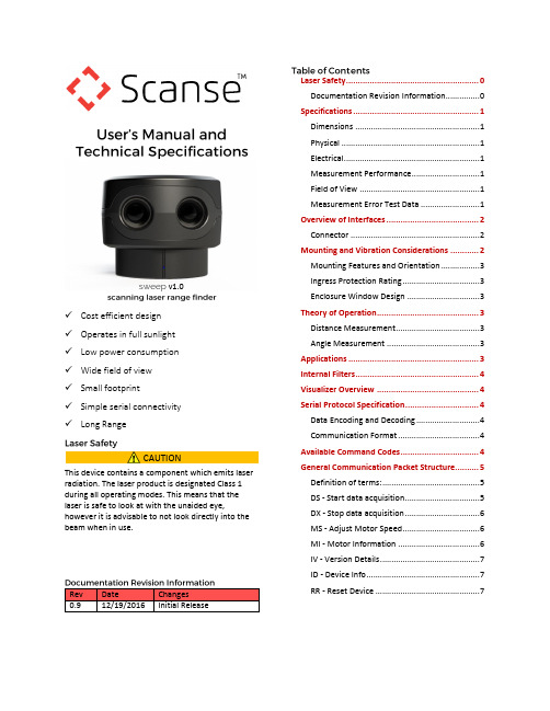
✓Cost efficient design✓Operates in full sunlight✓Low power consumption✓Wide field of view✓Small footprint✓Simple serial connectivity✓Long RangeThis device contains a component which emits laser radiation. The laser product is designated Class 1 during all operating modes. This means that the laser is safe to look at with the unaided eye, however it is advisable to not look directly into the beam when in use.Rev Date Changes0.9 12/19/2016 Initial Release Laser Safety 0Documentation Revision Information 0Specifications (1)Dimensions (1)Physical (1)Electrical (1)Measurement Performance (1)Field of View (1)Measurement Error Test Data (1)Overview of Interfaces (2)Connector (2)Mounting and Vibration Considerations (2)Mounting Features and Orientation (3)Ingress Protection Rating (3)Enclosure Window Design (3)Theory of Operation (3)Distance Measurement (3)Angle Measurement (3)Applications (3)Internal Filters (4)Visualizer Overview (4)Serial Protocol Specification (4)Data Encoding and Decoding (4)Communication Format (4)Available Command Codes (4)General Communication Packet Structure (5)Definition of terms: (5)DS - Start data acquisition (5)DX - Stop data acquisition (6)MS - Adjust Motor Speed (6)MI - Motor Information (6)IV - Version Details (7)ID - Device Info (7)RR - Reset Device (7)CAUTION sweep v1.0ALL DIMENSIONS ARE IN MM, DRAWINGS ARE NOT TO SCALE Figure 1, Sweep Dimension Drawing Specification ValueWeight 120 g (4.23 oz.) Operating Temperature -20 to 60° C (-4 to 140°F) Storage Temperature -40 to 80° C (-40 to 176°F) Specification ValuePower 5VDC ±0.5VdcCurrent Consumption Up to 650mA450mA nominal Specification ValueRange(75% reflective target)40 m (131ft) Resolution 1 cm (0.4 in)Update Rate(75% reflective target) Up to 1075Hz (see“Theory of Operation”)Sweep is a single plane scanner. This means that asits head rotates counterclockwise, it records data ina single plane. The beam starts out at approximately12.7mm in diameter and expands by approximately0.5 degrees as show in Figure 2.Figure 2, Sweep Field of View1020300%5%10%15%20%25%30%01000200030004000±cmMeasurementVariability%ErrorRange in CentimetersLong Range Error With 75% Reflective Target1020300%5%10%15%20%25%30%0100200300400500±cmMeasurementVariability%ErrorRange in CentimetersClose Range Error With 75% Reflective TargetSpecification ValueHorizontal Field of View 360 degreesVertical Field of View 0.5 degreesSweep can be connected to low level micro controllers directly using its serial port, or to a PC using the provided USB to serial converter.Figure 4, Sweep Cable DiagramSweep has two serial port connectors with identicalsignals. This allows for more mounting options.Figure 5, Sweep Pigtail Cable Connector DetailPin Color Function1 Red 5 Vdc (+) (minimum 0.5A capable)2 Orange Power enable (internal pull-up)3 Yellow Sync/Device Ready4 Green UART RX 3.3V (5V compatible)5 Blue UART TX 3.3V (5V compatible)6 Black Ground (-)You can create your own cable if needed for yourapplication. These components are readily available.Part Description Mfg. Part No.ConnectorHousing6-Position,rectangularhousing, latch-lock connectorreceptacle with1.25 mm(0.049 in.) pitch.JST GHR-06V-SConnectorterminal26-30 AWG crimpsocket connectorJST SSHL-002T-P0.2Wire UL 1061 26 AWGstranded copperN/A N/ASweep can be mounted in any orientation. Sweep’srotating head is dynamically balanced, which meansit is immune to linear vibration, but it can beaffected by rotational vibration. Sudden rotationalshocks can cause the head to either slow down orspeed up, which can affect data accuracy. If Sweep isrotationally jerked hard enough, it can cause themotor to lose sync, which will trigger a momentarymotor pause, and then restart.DRAWINGS ARE NOT TO SCALEFigure 6, Sweep Connector DiagramSweep has four brass threaded inserts designed to fitM2.5X0.45 screws in its base. These are the bestfeatures for mounting Sweep to an application. Thescrew holes are aligned with the scanner’smeasurement angles. The scanner’s zero degreestarting angle is aligned with the status LED, asshown in Figure 7.Sweep is rated as IP51, which is to say, it is not dustor water tight. It is recommended that Sweep beplaced inside a protective transparent enclosure if itwill be used in dusty or wet environments.Figure 7, Sweep Mounting Features (all dimensions in mm) Sweep uses 905nm laser light, which passes through several kinds of clear glass and plastic very well. Based on our testing, clear Polycarbonate plastic is one of the best choices, as it can be molded to fit the profile of the application’s enclosure, is very inexpensive, and in most cases, is more than 95% translucent to Sweep’s light beam. Factors that can affect the performance of a window are:∙Thickness of the window. Thicker windows will block more light, as well as bend the light more if the beam is not hitting the window normal to the surface.∙Scratches and dust. The presence of scratches and dust on the window will scatter the laser light, and may reflect some of the light back into the sensor’s detector, causing measurement errors.∙Surface coatings. There are a variety of coatings that can help with the performance of windows. One is an anti-reflective (AR) coating, which can help reduce the amount of laser light that is reflected as it passes through the window’s surface.Sweep employs a time of flight ranging method. This technique involves transmitting a packet of micro pulses of light in a unique pattern. When this light bounces off an object and returns to the receiving detector, a correlation algorithm is used to identify the unique light pattern from ambient noise. Each light packet is different from the last, which allows multiple Sweep sensors to operate adjacent to each other without interference.The light packets that Sweep uses can vary, which can affect accuracy of range measurements, as well as the maximum range and update rate. Under normal operation, Sweep limits the maximum time per measurement to around 1ms. Sometimes if not enough light is returned from the environment, the measurement fails, and a 1 is returned as the range value. On the other hand, if allot of light is returned from the environment, the correlation algorithm can reach its maximum accuracy early, and can return a range value in less than 1ms. This is what makes the update rate of Sweep variable.Sweep uses an optical encoder to measure the angle of the rotating sensor head. The angle that is recorded for a range data point is the angle the sensor is at when the measurement is completed.Sweep can be used for a variety of applications, including robot guidance/obstacle avoidance, 3D scanning, surveying, people tracking and many more.Sweep has the ability to perform some simple data filtering within the sensor itself. These filters are still in development, and are being made for specific customer segments. Examples include having Sweep split up its field of view into eight sections, then transmit only the closest objects within each of those sectors. Another example is to have Sweep only output data from a range of angles. If you have an application that requires a specific filter, please contact us.You can download the Sweep visualizer at www.scanse.io/downloadsThe purpose of the Scanse visualizer is to provide a way to quickly evaluate Sweep’s performance in your application/environment. For some applications, like surveying, our visualizer can be used to take quick measurements between range data points within a scan. It contains a programming tool for updating Sweep’s firmware.A full tutorial for using the visualizer can be found in software support section at support.scanse.io. Specification ValueBit Rate 115.2 KbpsParity NoneData Bit 8Stop Bit 1Flow Control NoneAll characters used for commands and responses are ASCII code in addition to CR and LF, except for the measurement packet.Responses with float values are sent as 16bit integer values.Example conversion:angle_f = 1.0f * ((float)(angle_i >> 4) + ((angle_i & 15) / 16.0f));All communication packets between the host computer and the sensor begin with ASCII letter command codes. ASCII Code (2 bytes) FunctionDS Start data acquisitionDX Stop data acquisitionMS Adjust Motor SpeedMI Motor InformationIV Version InfoID Device InfoRR Reset Device(HOST -> SENSOR) Command with no parameterCommand Symbol (2 bytes) Line Feed (LF)Example: DS, DX, MS, MI, IV…Line Feed (LF) or Carriage Return (CR) orCommand with parameterCommand Symbol (2 bytes) Parameter(2 bytes)Line Feed(LF)(SENSOR -> HOST)Response with no parameter echoedCommand Symbol (2 bytes) Status(2 bytes)Sum of Status Line Feed(LF)orCommand with parameter echoedCommand Symbol (2 bytes) Parameter(2 bytes)Line Feed(LF)Status(2 bytes)Sum of Status Line Feed(LF)Command Symbol: 2 byte code at the beginning of every command.Parameter: Information that is needed to change sensor settings.Line Feed (LF) or Carriage Return (CR): Terminating code. Command can have LF or CR or both as termination code but reply will always have LF as its termination code.Status: 2 bytes of data in reply that informs normal processing if command is authenticated or errors if undefined, invalid or incomplete command is received by sensor. Status other than 00 and 99 are error codes.Sum of Status: 1 byte of data used in authentication. Calculated by adding status bytes, taking lower 6 byte of this sum and adding 30H to this sum.Sum = 111111 = 3fH+30H = 6fH = oExample: [LF] 0 0 [LF] = PResponses to Invalid Commands: 11 -- Invalid parameter∙Initiates scanning∙Responds with header containing status.∙Next responds with measurement packets indefinitely until commanded to stop.(HOST -> SENSOR)D S LF(SENSOR -> HOST)Header responseD S Status(2 bytes) SUM(2 bytes)LFData Block (7 bytes) Data BlockSync/Error (1 byte) Azimuth - degrees(float)(2 bytes)Distance - cm(int)(2 bytes)Signal Strength (1byte)Checksum(1 byte)sync / error: 0 bit indicates the sync value, a value of 1 indicates the packet is the beginning of a new scan, a value of 0 indicates all other measurement packets. Bits 1-6 are reserved for error codes.azimuth: Angle that ranging was recorded at. Azimuth is a float value - needs to be converted from 16bit int to float, use instructions at the topdistance: Distance of range measurement.signal strength: Signal strength of current ranging measurement. Larger is better. Range: 0-255checksum: Calculated by adding the 6 bytes of data then dividing by 255 and keeping the remainder. (Sum of bytes 0-6) % 255Status00 -- Command received without any Error22 -- Stopped to verify error55 -- Hardware trouble99 -- Resuming operationStops outputting measurement data.(HOST -> SENSOR)D X LF(SENSOR -> HOST)D X Status SUM LFDefault Speed: Sensor stores last speed command in non-volatile memory, and will return to that speed after a power cycle, except if the last state was speed 00 (stopped).(HOST -> SENSOR)M S Speed Parameter (2 bytes)LFSpeed Parameter: 00 - 10 : 10 different speed levels according to revolutions per second (Hz), increments of 1. Example: 01,02,..00 = Motor stopped(SENSOR -> HOST)M S Speed(Hz)(2 bytes)LF Status Sum LFReturns current rotation frequency in Hz in ASCII 00 - 10 (increments of 1) (HOST -> SENSOR)M I LF(SENSOR -> HOST)M I Speed(Hz)(2 bytes)LF Status Sum LF∙Model∙Protocol Version ∙Firmware Version ∙Hardware Version ∙Serial Number (HOST -> SENSOR)I V LF (SENSOR -> HOST)I V Model(5 bytes)Protocol(2 bytes)Firmware Version(2 bytes)Hardware Version(1 byte)Serial Number(8 bytes)LFExample: IVSWEEP01011100000001I V SWEEP 01 01 1 00000001 LF ∙Bit Rate∙Laser State∙Mode∙Diagnostic∙Motor Speed∙Sample Rate(HOST -> SENSOR)I D LF(SENSOR -> HOST)I D Bit Rate(6 bytes)Laser state Mode DiagnosticMotor Speed(2 bytes)Sample Rate(4 bytes)LFExample: IV115200110050500I D 115200 1 1 0 05 0500 LF ∙Reset Scanner(HOST -> SENSOR)R R LF(SENSOR -> HOST)R R Status Sum LF。
激光传感器使用说明书
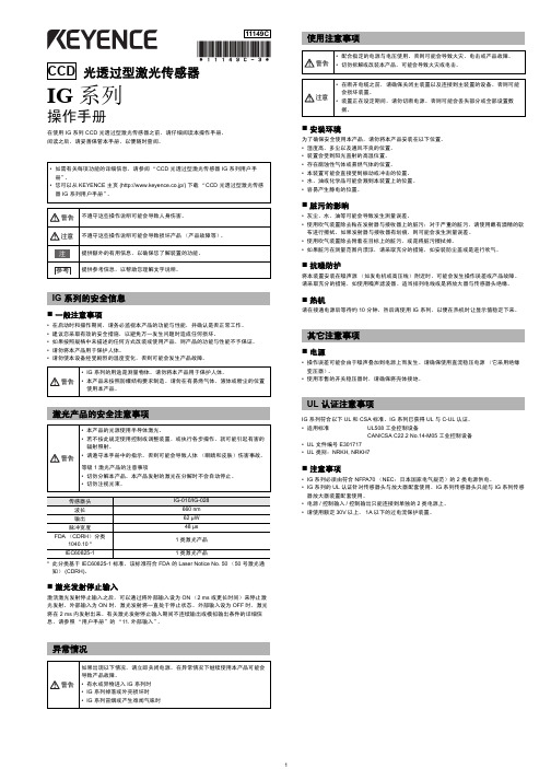
光透过型激光传感器IG 系列操作手册在使用 IG 系列 CCD 光透过型激光传感器之前,请仔细阅读本操作手册。
阅读之后,请妥善保管本手册,以便随时查阅。
IG系列的安全信息⏹一般注意事项•在启动时和操作期间,请务必监视本产品的功能与性能,并确认是否正常工作。
•建议您采取有效的安全措施,以避免万一发生问题时造成任何损坏。
•如果按照规格中未描述的任何方式改装或使用产品,则产品的功能与性能不予保证。
•请勿将本产品用于保护人体。
•请勿使本设备经受剧烈的温度变化,否则可能会发生产品故障。
*此分类基于 IEC60825-1 标准,该标准符合 FDA 的 Laser Notice No. 50(50 号激光通知)(CDRH)。
⏹激光发射停止输入激活激光发射停止输入之后,可以通过将外部输入设为 ON(2 ms 或更长时间)来停止激光发射。
外部输入为 ON 时,激光发射将一直处于停止状态。
外部输入设为 OFF 时,激光将在 2 ms 内发射出来。
有关激光发射停止输入期间不连续输出或模拟输出条件的详细信息,请参照“用户手册”的“11. 外部输入”。
异常情况使用注意事项⏹安装环境为了确保安全使用本产品,请勿将本产品安装在以下位置。
•湿度高、多尘以及通风不良的位置。
•装置会受到阳光直射的高温位置。
•存在腐蚀性气体或易燃气体的位置。
•本装置可能会直接受到振动或冲击的位置。
•水、油或化学品可能会溅到本装置上的位置。
•容易产生静电的位置。
⏹脏污的影响•灰尘、水、油等可能会导致发生测量误差。
•使用吹气装置除去粘在发射器与接收器上的脏污;对于严重的脏污,请使用蘸有酒精的软布进行擦拭。
如果发射器与接收器有划痕,则可能会发生测量误差。
•使用吹气装置除去附着在目标上的脏污,或是将脏污擦拭掉。
•如果脏污在测量范围内漂浮,请采取充分的措施,如安装防尘盖或是进行吹气。
⏹抗噪防护将本装置安装在噪声源(如发电机或高压线)附近时,可能会发生操作误差或产品故障。
激光测距传感使用手册

激光测距传感使用手册前言尊敬的客户:衷心的感谢您选择了深圳市南方测控技术有限公司的激光测距传感器!为了让您更好的使用本激光测距传感器与防止意外事故的发生,请您在使用本激光测距传感器前仔细的阅读本说明书。
本说明书的版权归属深圳市南方测控技术有限公司所有,如在不影响本激光测距传感器整体性能的前提下所作的修改或更新,恕不另行通知。
激光测距传感器系统说明术语解释➢激光测距:利用激光对目标的距离进行准确测定。
激光测距一般采用两种方式来测量距离:脉冲法和相位法。
➢脉冲激光测距:基于激光脉冲反射时差法原理,测距仪器发射出的激光经被测量目标反射后,激光束被测距仪器接收,测距仪器记录激光往返的时间。
光速和往返时间的乘积的一半,就是测距仪器和被测量物体之间的距离。
➢激光测距传感器:为工业测量之产品,采用工业标准设计、生产和检测,可在线24小时连续实施测量,有的可以多台组网测试。
➢激光安全等级:国际上对激光有统一的分类,激光器分为四类(Class1、Class2、Class3、Class4)。
Class1激光器对人是安全的,Class2激光器对人有较轻的伤害,Class3以上的激光器对人有严重伤害,使用时需特别注意,避免对人眼直射。
➢Class2激光器:指激光器的出口光功率小于1mw,一般认为对人的眼睛是安全的,正常暴露在这种激光器的光束下不会对眼睛的视网膜造成永久性的伤害。
尽管此种激光器是安全的,但也不能长时间的直视激光光束。
如偶尔照射到人眼还不至于引起伤害,但连续观察激光束时能损伤眼睛。
此是对第二级激光器的最重要控制措施。
➢系统概述LPS系列激光测距传感器是一种功能强大的测量精确、无接触式的工业用距离测量设备,它可广泛地被集成用于各种工业用途的控制和监测系统上。
使用图例如下:LPS系列激光测距传感器是一款使用方便的工业应用激光测距仪表,特别为交通、炼钢、仓储、建筑、码头等需要自动进行距离和位置控制的应用而设计研发,具有很高地实用性。
KEYENCE CCD激光测量仪中文说明书

配套使用具有相同序列号的发射器和接收器。如果配套使用具有不同序列号 的装置,则操作与精度不予保证。序列号位于发射器与接收器的顶部。
发射器
IG-028 (28 mm 宽)
SERIAL No.
接收器
No.
12345678
12345678
发射器 (T) x 1
接收器 (R) x 1
安装放大器
DIN 导轨安装型,主装置 (IG-1000)
• 如需有关每项功能的详细信息,请参阅 “CCD 光透过型激光传感器 IG 系列用户手 册” 。 • 您可以从 KEYENCE 主页 (http://www.keyence.co.jp/) 下载 “CCD 光透过型激光传感 器 IG 系列用户手册” 。
脏污的影响
警告 注意 注 参考
不遵守这些操作说明可能会导致人身伤害。 不遵守这些操作说明可能会导致损坏产品 (产品故障等) 。 提供额外的有用信息,以确保您了解装置的功能。 提供参考信息,以帮助您理解文字说明。 • 灰尘、水、油等可能会导致发生测量误差。 • 使用吹气装置除去粘在发射器与接收器上的脏污;对于严重的脏污,请使用蘸有酒精的软 布进行擦拭。 如果发射器与接收器有划痕,则可能会发生测量误差。 • 使用吹气装置除去附着在目标上的脏污,或是将脏污擦拭掉。 • 如果脏污在测量范围内漂浮,请采取充分的措施,如安装防尘盖或是进行吹气。
面板安装型 (IG-1500/IG-1550)
(1)
面板安装型
IG-1500 (主装置)
(16) (15) (14)
(2) (3)
面板安装工具 x1
(4) (5) (13)
放大器 x 1
前保护盖 x1
电源线 / 输入 输出电缆 (2 m) x 1 (电缆芯数 : 12)
镭神激光传感器产品手册说明书

目录镭神LS10A系列激光传感器 (3)镭神LS10B系列高速高精度激光传感器 (5)镭神LS11A系列激光位移传感器 (7)镭神LS11B系列高速激光位移传感器 (9)镭神LS50系列TOF激光测距传感器 (11)镭神相位法激光传感器 (12)镭神三维激光扫描仪 (13)镭神LS10A系列激光传感器LS10A基本概况LS10A系列激光传感器是深圳市镭神智能系统有限公司研发的近距离高精度的非旋转扫描测距产品。
该传感器运用激光三角法测量物体三维尺寸,可完成物体检查、定位、测量等多种工作任务,帮助客户提高生产力,实现生产控制和质量控制。
LS10A系列激光传感器的扫描频率30Hz,采用USB接口输出数据,根据测量尺寸的不同,可划分为不同的产品型号,具体参数如下表所示。
产品参数LS10A-050 LS10A-095 LS10A-245 LS10A-350 量程起点50mm 70mm 170mm 200mm量程中点55mm 95mm 245mm 350mm量程终点60mm 120mm 320mm 500mm 高度方向测量范围10mm 50mm 150mm 300mm±0.17%FSO ±0.10%FSO ±0.13%FSO ±0.40%FSO5μm 20μm 50μm 1200μm 量程起点10mm 14mm 34mm 40mm量程中点11mm 19mm 49mm 70mm量程终点12mm 24mm 64mm 100mm360测量点/扫描线标准655nm 655nm 655nm 655nm可选405nm 405nm 405nm 405nm2M5mW 8 mW 10 mW 15 mW30° 30° 30° 30°10000lx 10000lx 5000lx 5000lx30Hz 30Hz 30Hz 30HzUSBUSB不锈钢5VDC,±10%IP65阳极氧化铝/不锈钢PMMA/安全玻璃15g2g/20~500Hz0℃~40℃-20℃~+70℃产品应用物体检查形状测量镭神LS10B系列高速高精度激光传感器LS10B基本概况LS10B系列激光传感器是深圳市镭神智能系统有限公司研发的高速高精度的扫描测距产品。
E+L-KRS60探边系统说明书
1.安全操作事项1.1文档材料要时刻保持文件材料要放在安全和易拿到的地方。
文件材料是交付的一部分且必须在安装,操作生产和日常维修之前仔细阅读。
我们的文档本质上由高级系统描述(A),个别部件的描述(B,C,…W),备用件清单(X)和电路图(Z)组成。
进程要与系统描述里的说明相一致。
所有重要的进程都在系统描述中有说明。
如果有需要,个别部件的描述可以用来参考。
在方框图中可以找到你们系统的原理图解。
由于数码组件也是由我们公司配置,也可以在方框图中找到地址设置。
1.2准备使用布边导正器只能被用来横向导正材料。
它定位进布摆臂到材料的真实位置确保将材料的边缘正确导到针上。
布边导正器只能允许被安装到E+L确认的客户机台上。
布边导正器不允许被修改。
布边导正器是由最先进技术制造。
然而,操作过程中—对用户的健康危害或者—财产损失有可能发生。
只有在下列情况下使用我们的纠偏器—在正确的工作引导下,—在观察现场的生产情况,规定或习惯性的安全守则还有防止意外事故的规章,都要给予安全和危险足够的重视。
1.3用户提供的安全设备有几个点包括来回运动的摆臂,马达,排齿或者极限开关,都需要用户包装保护。
1.4使用群体在这个文档中所描述的活动只允许以下表格中的特定用户才能有资格操作。
2.功能2.1目的布边导正器的目的是定位摆臂到正确的位置以确保布边能正确地上到针板上。
2.2 设计图2-1:布边导正器设计图KRS60布边导正器包括:1)两个FR 55电眼2)两个马达(带控制板RK 4080)3)两个排齿4)两双排齿限位开关NT 80-045)两个急停开关ATL 01016)两个控制盒NT 53037)一个控制盒NT 51122.2.1附件每一个纠偏器都能装备一下的附件:—机械展边装置LS,电动展边LA 8或者气动展边LP 03,—漏针防护FM 05012.2.2马达设计图表2-2:马达设计马达包括:1)一个带RK 4080的支架臂2)一个排齿锁3)一个齿轮电机(无刷)4)一个带锁环和防尘罩的中柱5)一个带齿条固定座的排齿(可选)2.3工作原理图表2-3:布边导正器的工作原理,举例展边设备(1)展开卷曲的边缘使布边能被扫描和准确上针。
USN60使用说明书1-2

1.了解键盘、菜单系统和显示USN60是超声波探伤仪和测厚仪。
它能够在数据库里存储A-扫描,操作参数和各种各样的测厚数据。
在本章中你将了解USN60的菜单和功能。
仔细阅读本章的内容将帮助你更好的使用本手册在阅读完这一章后,你将能够: 1. 在仪器上安装电池(1.1节) 2. 开启仪器(1.2节)3. 了解键盘上每一个键的功能(1.3节)4. 使用内置菜单系统进入USN60的所有功能(1.4节)5. 解释显示中最常出现的符号(1.5节)6. 列出USN6的特性(1.6节)7. 找出本手册中所包含内容的章节(1.7节)8. 确定哪一种可选特性被安装在你的仪器中(1.8节)1.1 电池的安装USN60通过安装在防护外壳后部的六个D 型电池或可选的交流电源适配器工作(见图1-1)。
要打开电池盒盖首先应松开四颗螺钉。
建议使用9.0安的镍氢充电电池,也可用碱性或镍镉充电电池。
如果使用碱性或镍镉电池,一定要按照本手册第二章第一节所讲述的步骤正确安装。
无论你使用哪一种电池,一定要按照电池盒中标明的电极方向并参照图1-1所示正确的安装。
图1-1在如图所示位置装入电池,注意交流电源适配器接口的位置电池电量的多少通过图标显示(见图1-2)。
安装新电池后,图标将显示电量充足;随着电量的消耗,图标逐渐显示出电量不足。
需要注意的是此图标只正确的显示本手册第2章第1节中所要求使用的电池的电量情况。
当图标显示电池电量仅剩四分之一时,应尽快更换新电池。
若因电池电量太弱导致仪器不能正1.2 仪器的电源开关按下三秒钟即可开或关仪器。
1.3 键盘和旋钮的特性USN60的设计方便操作者快速进入仪器的所有功能。
通过易于操作的菜单系统,只需不超过3个键的按压即可进入任何一种功能(如图1-2)。
要进入任何一种功能你只需:●按下七个菜单键选择菜单,在显示底部的菜单将迅速被所选菜单中的子菜单所替代。
●再按下一个菜单键所需功能的子菜单。
●显示屏右边的功能栏中将显示四种功能,通过按压四个功能键你需要的功能。
Insight-60激光测距传感器用户手册
Insight-60激光测距传感器用户手册目录一前言 (3)二仪器特点 (3)三安全说明 (3)3.1 基本事项 (3)3.2 仪器的禁用范围 (3)3.3注意事项及保养 (4)3.4 激光等级 (4)四技术参数 (5)4.1 激光参数 (5)4.2 工作参数 (5)4.3 接口及指示灯 (5)4.3.1 DB9接口定义 (6)4.3.2 电源插座 (6)4.3.3 激光发射及接收口 (6)五通讯协议 (7)5.1 基本命令 (7)5.1.1 读设备地址 (7)5.1.2 读当前距离 (7)5.1.3 读最大距离 (7)5.2 扩展命令 (7)5.2.1命令格式 (7)5.2.2 开机信号 (7)5.2.3 测量 (8)5.2.4 查询设备地址 (8)5.2.5 设定设备地址 (8)5.2.6 设定偏移量 (8)5.2.7 查询偏移 (8)六、4-20mA电流环 (9)本手册里除了使用说明外,还包括了重要的安全说明。
在使用本仪器前,请务必仔细阅读本手册。
请您记住仪器型号和仪器编号,当您需要与销售商或授权的维修部联系时,会用到这些信息。
一、前言INSIGHT‐200 激光测距传感器是新一代的测距设备,功能强大、坚固耐用,专为工业测量场合设计。
该设备拥有许多卓越的性能.是一种当前最为先进的经济型在线位置检测系统,具有惊人的测试精度和极高的稳定性。
二、仪器特点✧无接触测量,保证测量人员人身安全。
✧基本不受天气条件影响,不论白天、夜晚、刮风、有雾天气都可进行测量。
✧体积小、重量轻、便于工作人员野外操作。
✧测量结果精度高,测量速度快,极大的提高了工作效率。
✧仪器测量操作简单直观,容易上手。
✧在隧道内可方便快速的测量。
✧测量结果无需换算,测量结果即为实际值。
三、安全说明3.1 基本事项本仪器为激光电气设备,非正常使用会造成危险。
仪器负责人必须保证按照《用户手册》来操作仪器,确保使用人员按照规程来使用仪器。
3.2 仪器的禁用范围✧在未阅读本说明书的情况下启动本仪器✧在仪器指定的使用范围之外使用。
激光传感器说明书
激光传感器说明书篇一:激光测距仪使用说明激光测距仪使用说明一、使用前的准备(一)电池的装入/更换打开仪器尾部的固定挡板。
向前推卡钮,向下将底座取下。
按住红色的卡钮推开电池盒盖。
安装或更换电池。
关闭电池盒盖,安装底座和卡扣。
当电池的电压过低时,显示屏上将持续闪烁显示电池的标志{B,21}。
此时应及时更换电池。
1、按照极性正确装入电池。
2、使用碱性电池(建议不要使用充电电池)。
3、当长时间不使用仪器时,请取出电池,以避免电池的腐蚀。
更换电池后,设置和储存的值都保持不变。
(二)多功能底底座固定挡板可以在下面的测量情况下使用:1、从边缘测量,将固定挡板拉出,直到听到卡入的声音。
2、从角落测量,将固定挡板拉出,直到听到卡入的声音,轻轻将固定挡板向右推,此时固定挡板完全展开。
仪器自带的传感器将辨认出固定挡板的位置,并将自动设置测量其准点。
(三)内置的望远镜瞄准器在仪器的右部有一个内置的望远镜瞄准器。
此望远镜瞄准器为远距离测量起到辅助的作用。
通过瞄准器上的十字丝可以精确地观察到测量目标。
在30米以上的测量距离,激光点会显示在十字线的正中。
而在30米以下的测量距离,激光点不在十字线中间。
(四)气泡一体化的水泡使仪器更容易调平。
(五)键盘1、开/测量键2、第二级菜单功能3、加+键4、计时(延迟测量)键5、等于[=]键6、面积/体积键7、储存键8、测量基准边键9、清除/关键10、菜单键11、照明键12、间接测量(勾股定律)键13、减-键14、BLUETOOTH(六)显示屏1、关于错误测量的信息2、激光启动3、周长4、最大跟踪测量值5、最小跟踪测量值6、测量基准边7、调出储存值8、储存常数9、主显示10、单位,包括乘方立方(2/3)11、顶的面积12、墙面积13、3个额外显示(如:测量中间值)14、BLUETOOTH蓝牙开/关15、第二级菜单功能开16、硬件故障17、间接测量-利用勾股定律18、间接测量-利用勾股定律-部分高度19、面积/体积20、带常数的测量21、电池充电量显示二、菜单功能(一)设置在菜单中可以改变设置,并将其长久保存,并在关机和更换电池后不改变。
激光式边缘检测传感器˙检测头LD-60
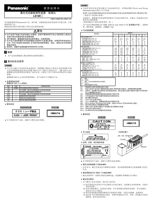
●● 激光照射指示灯(绿色)(只有LD-601) • 激光在照射中,检测头的绿色LED亮起。此LED灯带眼镜也可以确认。
●● 警告标签
日语/英语记载
中文记载
●● 在中国使用本产品时,请贴中文警告标签(附属)。
LD-601
●● 为保护使用者免受使用激光产品造成的危害,在FDA规格(Food and Drug Administration)制定了以下标准。
PART 1040(PERFORMANCE STANDARDS FOR LIGHTEMITTING PRODUCTS) ―放射光产品的执行标准―
根据GB 7247.1-2012危害类别的规定,本产品相当于1类激光产品。
●● 危害类别的说明 根据GB 7247.1-2012附录C
类别
1类 1M类 2类 2M类 3R类 3B类 4类
机种 LD-600
- - - - - -
危害类别的说明 在可合理预见的情况下是安全的 与1类相同,通过光学仪器直接进行光束内视可能有害 低功率;由回避反应提供正常的眼保护 与2类相同,通过光学仪器直接进行光束内视可能有害 直接光束内视可能是有害的 直接光束内视通常是有害的 高功率;漫反射可能是有害的
性能(所有激光产品) 保护机箱[1040.10(f)(1)] 安全连锁[1040.10(f)(2)] 控制装置的位置[1040.10(f)(7)] 观察光学装置[1040.10(f)(8)] 扫描安全装置[1040.10(f)(9)]
性能(激光系统) 遥控控制连接器[1040.10(f)(3)] 主控制器[1040.10(f)(4)] 放射指示器[1040.10(f)(5)] 光束衰减器[1040.10(f)(6)] 复位[1040.10(f)(10)]
大有激光测距仪说明书(lm60)

到这个激光束的射出位置,使用时也要注意工作 场所附近一些人员,以免激光束直射到人眼引起 伤害。
激光辐射 不要直视激光束
2类激光产品 激光最大输出功率:P≤1mW 激光波长:λ=620-690nm 本产品符合标准 EN60825-1: 2007
6
液晶显示 指示电池满电量 指示电池低电量
指示测量基准是从激光测距仪的延伸杆为 起点 指示测量基准是从激光测距仪的尾端为起 点 指 示测量基准是从激光测距仪的三脚架连 接螺母位置为起点 指示测量基准是从激光测距仪的前端为起 点
激打开指示
指示当前在单段距离测量模式 指示当前在面积测量模式 指示当前在体积测量模式 指示当前在单勾股定理测量模式 指示当前在双勾股定理测量模式 指示当前在最小值测量模式 指示当前在最大值测量模式 指示当前在连续测量模式
了解数字激光测距仪 ( 图 1) 本激光测距仪外形轻巧、握持舒适、操作携带方 便,测距精确、快速。 ●● 本仪器的测量量程为 0.1-60 米,精度高达
±2 毫米。 ●● 该仪器适用于:
●●测量长度、宽度、高度及间隙 ●●很难直接测量的场合,可以通过勾股定理进
行间接测量 ●●计算面积和体积 ●● 本仪器有自动关机功能。连续 5 分钟不使用
LM60 Manual 12-0921
8
安装电池 ( 图 3)
该激光测距仪使用 4 节“AAA”碱性电池工作。 1. 推动锁钩取下电池盖。 2. 装入 4 节新的“AAA”碱性电池,注意电池
盒内的电池极性标记,以保证装入电池极性 (+/-)正确。 3. 合上电池盖并卡到位。
图3
注意 : 当屏幕电量符号变空时请更换新电池。 长期不使用本仪器,请取出电池。 电池的品牌和型号都应该相匹配。 不要新旧电池混合使用。 及时取出废旧电池,按照当地相关法令处理废旧 电池。勿将电池扔到火中。
Leica_MS60_TS60用户手册
警告信息是仪器安全的基本理念的必要部分。 当出现任何危害或危险的情况下时,仪器会 提示。
警告信息 ... • 使用户注意关于使用该产品有关的直接和间接的危害。 • 包含一般的行为规则。
所有的安全说明和安全信息,都是为用户的安全着想,应严格遵守并遵循! 因此,手册对 于任何执行任务的人都是必要的。
Service myProducts myService mySupport myTraining
myTrustedServices
描述
添加您购买的所有 Leica Geosystems 产品。 查看您的产品的详细信 息,购买附加选项或客户关怀包 (CCPs),升级最新的软件并获取最 新的文档。
产看产品在 Leica Geosystems 维修中心的维修历史,和维修细节。 对于正在 Leica Geosystems 维修中心的产品,您可以查看当前的维 修状态,和估计的维修完成日期。
使用限制
仪器对环境条件的要求与人所能适应的环境条件相似:不适合在有腐蚀,易燃易爆的场合 使用。
在危险地区、与电力装置接近的地区或类似地区工作时,产品负责人一定要预先与当地的 安全主管机构和安全专家取得联系。
职责
Leica Geosystems AG, CH-9435 Heerbrugg,在下文中称为 Leica Geosystems,对所提供 的产品,包括用户手册和原装附件,在安全的使用条件下承担责任。
提供提高的生产力,和最高的安全。 • myExchange
您在 myExchange 中可以发送电脑中的任何文件 / 对象给您的 Leica Exchange 联系人。 • mySecurity 如果仪器被盗窃,可以将仪器锁定,使仪器无法继续使用。
VisiSight 微型光电传感器用户指南说明书

Technical DataOriginal InstructionsVisiSight Miniature Photoelectric SensorsCatalog Numbers 42JS-P2MNB1-F4, 42JS-P2MPB1-F4, 42JS-P2MNA2-F4, 42JS-P2MPA2-F4, 42JT-P2LAT1-P4, 42JT-P8LAT1-P4, 42JT-C2LAT1-P4, 42JS-D2MNA2-F4, 42JS-D2MPA2-F4, 42JS-D2MNA1-F4, 42JS-D2MPA1-F4, 42JT-D2LAT1-P4, 42JT-D8LAT1-P4, 42JS-B2MNB1-F4, 42JS-B2MPB1-F4, 42JS-B2MNB2-F4, 42JS-B2MPB2-F4, 42JT-B2LAT1-P4, 42JT-B2LAT2-P4, 42JT-B8LAT1-P4, 42JT-F5LET1-P4, 42JS-E2EZB1-F4, 42JS-R9MNA1-F4, 42JS-R9MPA1-F4, 42JS-E1EZB1-F4, 42JS-R9MNA2-F4, 42JS-R9MPA2-F4, 42JT-E2EZB1-P4, 42JT-R9LAT1-P4, 42JT-E8EZB1-P4, 42JT-R8LAT1-P4Topic PageSummary of Changes242JS VisiSight Sensor3Features3Available Models3Optical Response Time Characteristics3Specifications3Product Selection4User Interface4Wiring Diagrams5Approximate Dimensions5Typical Response Curves542JT VisiSight Sensor7Features7Available Models7Optical Response Time Characteristics7Specifications7Product Selection8User Interface9Wiring Diagrams942JT Push Button Lock/Unlock942JT Remote Teach9Approximate Dimensions9Typical Response Curves10Accessories12VisiSight Miniature Photoelectric Sensors Technical DataSummary of ChangesThis publication contains the following new or updated information. This list includes substantive updates only and is not intended to reflect all changes.Topic PageAdd UKCA Marked certification to Specifications tables 3 and 7Updated sensing distance for 42JT-B2LAT2-P482Rockwell Automation Publication 42JSJT-TD001B-EN-P - August 2023Rockwell Automation Publication 42JSJT-TD001B-EN-P - August 2023342JS VisiSight SensorFeatures42JS VisiSight™ sensors include the following features:•Visible red light-emitting diode (LED) for ease of alignment•Complementary light and dark operate outputs•Linear sensitivity adjustment knob or no adjustment models •Optional snap-on adaptor enables 18 mm mount and facilitates easy sensor replacement •I P67 rated enclosureAvailable Models•Polarized retroreflective •Standard diffuse•Fixed background suppression •Transmitted beamSpecificationsOptical Response Time Characteristics42JS 42JSAdapterAttribute 42JS VisiSight SensorCertifications cULus Listed, CE Marked for all applicable directives, and UKCA Marked for all applicable regulationsShock 30 g with 1 ms pulse duration, meets or exceeds IEC 60947-5-2Vibration 10…55 Hz, 1 mm (0.04 in.) amplitude, meets or exceeds IEC 60947-5-2Environmental Enclosure type rating IP67Operating temperature -20…+60 °C (-4…+140 °F)Relative humidity 5…95% (noncondensing)Ambient light immunity Incandescent light 5000 lux User Interface Status Indicator See User Interface on page 4Sensitivity adjustment No adjustment or adjustment knob by cat. no.Electrical Operating voltage 10…30V DC Current consumption 25 mA maxProtection type Short circuit, reverse polarity, false pulse, overload Outputs Output type See Product Selection on page 4.Output function Complementary light and dark operate Load current 100 mA max Mechanical Material •Housing: Plastic — ABS•Lens: Plastic — PMMA Connection typeSee Product Selection on page 4.Attribute [mm (in.)]Polarized RetroreflectiveDiffuse Background Suppression Transmitted BeamField of view 2.8°5.5° for 250 (9.8)4° for 800 (31.5)14° for 55 (2.16)17° for 130 (5.12)4°Spot size (1)(1)For more information on spot size, see Typical Response Curves on page 5.175 (6.89) @ 3.5 m (11.5 ft)40 (1.57) @ 250 (9.8)60 (2.36) @ 800 (31.5)7.6 (0.3) @ 55 (2.16)11.5 (0.45) @ 130 (5.12)700 (27.56) @ 10 m (32.8 ft)Light source Visible redVisible red and infraredResponse time1 ms4Rockwell Automation Publication 42JSJT-TD001B-EN-P - August 202342JS VisiSight SensorProduct SelectionUser Interfaceconnection (for example, 42JS-P2MPB1-A2), or -Y4 for a 4-pin DC pico (M8) QD connection on a 150 mm (6 in.) pigtail (for example, 42JS-P2MPB1-Y4).(2)Sensing distance with 92-124 reflector.Table 1 - Sensor IndicatorsRockwell Automation Publication 42JSJT-TD001B-EN-P - August 2023542JS VisiSight SensorWiring Diagrams(1)For normal operation, black wire (pin 4) needs no connection. To disable the lightsource, connect the black wire (pin 4) to +V.Approximate DimensionsTypical Response Curves+––Transmitted beam emitter+–PNP models withcomplementary outputsNPN models withcomplementary outputsM8PlugM12 Plug(1)M18X-40-30-20-10010203040B e a m D i a m e t e r (m m )(3.9)(7.87)(11.8)(15.7)(27.5)(31.5)(19.6)(23.6)(35.4)Distance [mm (in.)]Standard Diffuse—Beam Patternwithout 18 mm snoutwith 18 mm snout Distance [mm (in.)](0.39)(3.9)(39.4)1101001000O p e r a t i n g M a r g i nStandard Diffuse6Rockwell Automation Publication 42JSJT-TD001B-EN-P - August 202342JS VisiSight SensorBackground Suppression (55 mm)—Beam PatternDistance [mm (in.)](0.39)(0.78)(1.18)(1.57)(1.96)(2.36)B e a m D i a m e t e r (m m )-5-4-3-2-1023451Background Suppression (130 mm)—Beam PatternDistance [mm (in.)](0.79)(1.57)(3.15)(3.93)(4.72)(2.36)(5.51)B e a m D i a m e t e r (m m )-6-4-8-2-100210468Background Suppression (55 mm)Distance [mm (in.)](0.004)(0.04)(0.39)(3.9)O p e r a t i n g M a r g i n110100100001000Background Suppression (130 mm)Distance [mm (in.)](0.004)(0.04)(0.39)(3.9)(39.3)O p e r a t i n g M a r g i n1101001000010000-80-60-40-2020406080100B e a m d i a m e t e r [m m ](1.3)(2.6)(39.4)(5.2)(9.2)(10.4)(6.6)(7.9)(11.8)Distance [m (ft)]Polarized Retroreflective—Beam PatternPolarized Retroreflective110100O p e r a t i n g M a r g i n(0.33)(3.28)(32.8)(0.03)Distance [m (ft)]0-250-200-150-100-5050100150200250B e a m D i a m e t e r [m m ](6.56)(13.1)(19.7)(26.2)(32.8)Distance [m (ft)]Transmitted Beam—Beam PatternTransmitted Beam—Visible Red and Infrared1101001000O p e r a t i n g M a r g i n(0.33)(3.28)(32.8)(328)Distance [m (ft)]Rockwell Automation Publication 42JSJT-TD001B-EN-P - August 2023742JT VisiSight SensorFeatures42JT VisiSight™ sensors include the following features:•Class 1 eye-safe red laser beam (for small object and contrast detection) and visible light-emitting diode (LED) models•Unique auto PNP/NPN output reduces stocking cost and simplifies selection, installation, and maintenance •Teach push button for sensitivity and L.O./D.O. selection •IP69K enclosure rating and ECOLAB tested to withstand food industry cleaning chemicals•Laser etched markings for durabilityAvailable Models•Polarized retroreflective •Standard diffuse•Adjustable background suppression •Transmitted beam •Clear object •Color markSpecificationsOptical Response Time CharacteristicsAttribute 42JT VisiSight SensorCertifications cULus Listed, CE Marked for all applicable directives, and UKCA Marked for all applicable regulations Shock 30 g with 1 ms pulse duration, meets or exceeds IEC 60947-5-2Vibration 10…55 Hz, 1 mm (0.04 in.) amplitude, meets or exceeds IEC 60947-5-2Environmental Enclosure type rating IP67 and IP69K Operating temperature -20…+60 °C (-4…+140 °F)Relative humidity 5…95% (noncondensing)Ambient light immunity Incandescent light 5000 lux User Interface Status indicators See User Interface on page 9Sensitivity adjustment Teach button Electrical Operating voltage 10…30V DC Current consumption 30 mA maxProtection type Short circuit, reverse polarity, false pulse, overload Outputs Output type See Product Selection on page 8.Output function Teachable light or dark operate Load current 100 mA max Mechanical Material •Housing: Plastic — ABS •Lens: Plastic — PMMA Connection typeSee Product Selection on page 8.Attribute[mm (in.)]Polarized Retroreflective Clear Object Detection DiffuseBackgroundSuppressionColor Mark Transmitted Beam Visible Red 660 nm (except for Color Mark Models)Spot size (1)(1)For more information on spot size, refer to Figure on page 10.500 (19.7) @6 m (236.22 ft)40 (1.57) @ 1 m (3.28 ft)70 (2.75) @ 800 (31.5)15 (0.59) @ 180 (7.09)27 (1.06) @ 400 (15.75)1 x 4 (0.16) @ 12 (0.47)(white LED) 1.1 m (3.61 ft) @13 m (42.65 ft)Response time 0.5 ms 0.5 ms 0.5 ms 0.5 ms 50 µs0.5 ms Class 1 Laser 650 nmSpot size (1)14 (0.55) @13 m (42.65 ft)—0.6 (0.02) @ 250 (9.84) 1.3 (0.05) @ 120 (4.72)—13 (0.51) @ 18 m (59.05 ft)Response time 0.25 ms —0.333 ms 0.5 ms—0.25 ms42JT VisiSight SensorProduct Selectionexample, 42JT-P2LAT1-A2) or -F4 for a 4-pin DC micro (M12) QD connection on a 150 mm (6 in.) pigtail (for example, 42JT-P2LAT1-F4).(2)Sensing distance with 92-125 reflector.(3)Sensing distance with 92-118 reflector.8Rockwell Automation Publication 42JSJT-TD001B-EN-P - August 2023Rockwell Automation Publication 42JSJT-TD001B-EN-P - August 2023942JT VisiSight SensorUser InterfaceWiring Diagrams42JT Push Button Lock/UnlockThe push button or remote teach can be used to help prevent unauthorized users from changing teach settings.To lock the push button, press and release the button three times within 3 seconds. Both status indicators flash synchronously for 3seconds, which indicates that the push button is now locked.To unlock the push button, press and release the button three times within 3 seconds. Both status indicators flash asynchronously for 3seconds, which indicates that the push button is now unlocked.To lock the push button permanently, connect the white wire (pin 2) to -V.42JT Remote TeachThe sensor can be taught remotely via the white wire (pin 2).Connection to +V acts the same as the button being pressed and no connection is the same as the button not being pressed. The sensor can be taught by following the same teach/timing sequence as used in the push button teach (for example, connect to the +V for more than 3 seconds to teach the target, disconnect from the +V; remove the target and connect to the +V for less than 1 second to teach the no target condition). All push button functions can also be conducted via remote teach.Approximate DimensionsThe 42JT mounting holes are located toward the rear end of the sensor while the 42JS mounting holes are located toward the front. Both sensors are compatible with the industry standard 25.4 mm (1in.) mounting. The 42JT flexible mounting hole space range of 22.9…25.4 mm (0.9…1 in.) makes it compatible with the 24.1 mm (0.95 in.) hole space sensors.See rok.auto/systemtools for two-dimensional and three-dimensional CAD drawings.yellow status indicator is ON when the output is deactivated and OFF when it is activated.Transmitted beam emitterOutput wiring1212Normal operation: no connection.Remote teach: See 42JT Remote Teach section.Push button lock: connect to a -V. See the 42JT Push Button Lock/Unlock section.For Normal operation, white wire (pin 2) needs no connection. To disable lightsource, connect white wire (pin 2) to +V.3Output is PNP or NPN (push-pull) for color mark sensors.M12 PlugM8 Plug12M8 x 1(1.34)12(1.34)2.8(0.11)10Rockwell Automation Publication 42JSJT-TD001B-EN-P - August 202342JT VisiSight SensorTypical Response CurvesS i z e [m m ]Polarized Retroreflective Spot Size (6 m)Diffuse Spot Size (800 mm)Distance [mm (in.)]E x c e s s G a i nStandard Diffuse (800 mm)Distance [mm (in.)]Red Polarized Retroreflective (6 m)(6.6)(3.3)(13.1)(23)(16.4)(19.7)(9.9)101100E x c e s s G a i nDistance [m (ft)]1(3.3)2(6.6)3(9.9)4(13.1)5(16.4)6(19.7)7(23)10020030040050060003(9.9)6(19.7)9(29.5)12(39.4)15(49.2)10203092-1185(16.4)10(32.8)15(49.2)5101520S i z e [m m ]Laser Polarized Retroreflective Spot Size (13 m)Laser Polarized Retroreflective — Margin Curve (13 m)E x c e s s G a i nDistance [m (ft)]Distance [m (ft)]Distance [m (ft)]100010011010(0.4)800(31.5)600(23.6)400(15.75)200(7.87)0010203040506070800(31.5)600(23.6)400(15.75)200(7.87)S i z e [m m ]0510152025300200(7.87)150(5.91)100(3.94)50(1.96)250(9.84)Laser Diffuse Spot Size (250 mm)Laser Diffuse (250 mm)0.00.51.01.52.00200(7.87)150(5.91)100(3.94)50(1.96)250(9.84)Distance [mm (in.)] E x c e s s G a i nDistance [mm (in.)]S i z e [m m ]Rockwell Automation Publication 42JSJT-TD001B-EN-P - August 20231142JT VisiSight Sensor(1)The spot is square in shape with one side dimension per graph.Background Suppression (180 mm) — Spot SizeLaser Background Suppression (120 mm) — Spot SizeDistance [mm (in.)]E x c e s s G a i nLaser Background Suppression (120 mm)Distance [mm (in.)]Background Suppression (180 mm)E x c e s s G a i nDistance [m (ft)]Background Suppression (400 mm) — Spot SizeBackground Suppression (400 mm)E x c e s s G a i nDistance [m (ft)]Distance [m (ft)]Distance [m (ft)]5101520(7.87)(5.91)(3.94)(1.96)051015200(7.87)150(5.91)100(3.94)50(1.96)(0.79)(1.57)(2.36)(3.15)(3.94)(4.72)051015200.00.51.01.52.02.53.0020(0.79)40(1.57)60(2.36)80(3.15)100(3.94)120(4.72)0510152025300200(7.87)400(15.7)100(3.94)300(11.8)05101520(7.87)(15.7)(3.94)(11.8)S i z e [m m ]Distance [mm (in.)]789101112130608010012014151617E x c e s s G a i n [%] Color Mark(1)S i z e [m m ](1)S i z e [m m ](1)12Rockwell Automation Publication 42JSJT-TD001B-EN-P - August 202342JT VisiSight SensorAccessoriesRed Transmitted Beam (13 m) — Spot SizeRed Transmitted Beam (13 m)E x c e s s G a i nDistance [m (ft)] Laser Transmitted Beam (18 m) — Spot SizeLaser Transmitted Beam (18 m)E x c e s s G a i nDistance [m (ft)]Distance [m (ft)]Distance [m (ft)]S i z e [m m ]S i z e [m m ]100010010107.5(24.6)10(32.8)12.5(41)15(49.2)2.5(8.2)5(16.4)3(9.9)6(19.7)9(29.5)12(39.4)15(49.2)2004006008001000120005(16.4)10(32.8)15(65.6)20(65.6)51015510155(16.4)10(32.8)15(65.6)20(65.6)0.2(0.66)0.4(1.31)0.6(1.97)0.8(2.62) 1.0(3.28)10203040S i z e [m m ]*Distance [m (ft)]Clear Object Spot SizeDescription Cat. No.DC micro (M12) QD cordset, straight, 4-pin, 2 m (6.6 ft)889D-F4AC-2DC pico (M8) QD cordset, straight, 4-pin, 2 m (6.6 ft)889P-F4AB-2DC pico (M8) QD cordset, right angle, 4-pin, 2 m (6.6 ft)889P-R4AB-2Mounting bracketStainless steel, L-shaped for 42JT and 42JS60-BJS-L1Stainless steel, L-shaped for 42JS VisiSight 60-BJS-L2Stainless steel60-BKTL-SS Stainless steel, L-shaped for 42JT and 42JS VisiSight60-BJT-L2Plastic, swivel/tilt for 42JS VisiSight 60-2619Replacement, stainless steel, for replacing larger (50 x 50 mm) sensors60-BJT-RCS Protective, stainless steel, U-shaped for 42JT and 42JS60-BJT-U1Protective, stainless steel, horizontal and verticalfor 42JT and 42JS VisiSight 60-BJT-H1ReflectorCorner cube, 76 mm (3 in.) diameter 92-124Corner cube, 84 mm (3.3 in.) diameter 92-125Corner cube, 32 mm (1.5 in.) diameter 92-47Corner cube, 100 x 100 mm (4 x 4 in.)92-108Corner cube, 51 x 61 mm (2 x 2.5 in.)92-109Micro cube, 51 x 61 mm (2 x 2.5 in.) for laser and clear object models92-118DescriptionCat. No.VisiSight Miniature Photoelectric Sensors Technical Data Additional ResourcesThese documents contain additional information concerning related products from Rockwell Automation. You can view or download publications at rok.auto/literature.Resource DescriptionVisiSight Photoelectric Sensors Installation Instructions,publication 42JS-IN001Provides information to install and operate 42JS VisiSight photoelectric sensors.Series 7000 to 42JS VisiSight Replacement Kit Installation Instructions, publication 42JS-IN002Provides information on the kits that are designed to facilitate the transition of the Series 7000 photoelectric sensors to the 42JS VisiSight product family.42JS VisiSight Photoelectric Sensors Installation Instructions,publication 42JS-IN003Provides information to install and operate 42JS VisiSight photoelectric sensors.42JT VisiSight Photoelectric Diffuse Sensors with IO-Link InstallationInstructions, publication 42JT-IN001Provides information to install and operate 42JT VisiSight diffuse photoelectric sensors.42JT VisiSight Photoelectric Polarized Retroreflective Sensors with IO-Link Installation Instructions, publication 42JT-IN002Provides information to install and operate 42JT VisiSight polarized retroreflective photoelectric sensors.42JT VisiSight Photoelectric Transmitted Beam Sensors with IO-Link Installation Instructions, publication 42JT-IN003Provides information to install and operate 42JT VisiSight transmitted beam photoelectric sensors.VisiSight Photoelectric Background Suppression Sensors with IO-Link Installation Instructions, publication 42JT-IN004Provides information to install and operate VisiSight background suppression photoelectric sensors with IO-Link.42JT VisiSight Photoelectric Color Mark Sensors with IO-Link InstallationInstructions, publication 42JT-IN005Provides information to install and operate 42JT VisiSight color mark photoelectric sensors.42JT VisiSight Photoelectric Clear Object Sensors with IO-Link Installation Instructions, publication 42JT-IN006Provides information to install and operate 42JT VisiSight clear object photoelectric sensors.Industrial Automation Wiring and Grounding Guidelines, publication 1770-4.1Provides general guidelines for installing a Rockwell Automation industrial system. ProposalWorks™ configuration software, rok.auto/systemtools Helps configure complete, valid catalog numbers and build complete quotes based ondetailed product information.Product Certifications website, rok.auto/certifications Provides declarations of conformity, certificates, and other certification details.Rockwell Automation Publication 42JSJT-TD001B-EN-P - August 202313Publication 42JSJT-TD001B-EN-P - August 2023Supersedes Publication 42JSJT-TD001A-EN-P - July 2018Copyright © 2023 Rockwell Automation, Inc. All rights reserved. Printed in the U.S.A.Rockwell Automation SupportUse these resources to access support information.Documentation FeedbackYour comments help us serve your documentation needs better. If you have any suggestions on how to improve our content, complete the form at rok.auto/docfeedback .Technical Support CenterFind help with how-to videos, FAQs, chat, user forums, Knowledgebase, and product notification updates.rok.auto/support Local Technical Support Phone Numbers Locate the telephone number for your country.rok.auto/phonesupport Technical Documentation CenterQuickly access and download technical specifications, installation instructions, and user manuals.rok.auto/techdocs Literature LibraryFind installation instructions, manuals, brochures, and technical data publications.rok.auto/literature Product Compatibility and Download Center (PCDC)Download firmware, associated files (such as AOP, EDS, and DTM), and access product release notes.rok.auto/pcdcRockwell Automation maintains current product environmental compliance information on its website at rok.auto/pec .Allen-Bradley, expanding human possibility, ProposalWorks, Rockwell Automation, and VisiSight are trademarks of Rockwell Automation, Inc.Trademarks not belonging to Rockwell Automation are property of their respective companies.Rockwell Otomasyon Ticaret A.Ş. Kar Plaza İş Merkezi E Blok Kat:6 34752, İçerenköy, İstanbul, Tel: +90 (216) 5698400 EEE Yönetmeliğine Uygundur。
In-Sight说明书
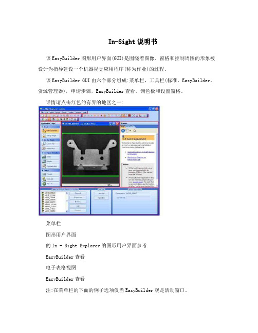
In-Sight说明书该EasyBuilder图形用户界面(GUI)是围绕着图像。
窗格和控制周围的形象被设计为指导建设一个机器视觉应用程序(称为作业)的过程。
该EasyBuilder GUI由六个部分组成:菜单栏,工具栏(标准,EasyBuilder,资源管理器),申请步骤,EasyBuilder查看,调色板和设置窗格。
详情请点击红色的有界的地区之一:菜单栏图形用户界面的In - Sight Explorer的图形用户界面参考EasyBuilder查看电子表格视图EasyBuilder查看注:在菜单栏的下面的例子选项仅当EasyBuilder观是活动窗口。
菜单栏包括以下分支:文件菜单:开始新的就业机会,打开和保存工作或图像。
在打印前预览工作的结果表,打印结果表并退出EasyBuilder硬拷贝。
编辑菜单:撤消和重做操作,请执行选定的工具的图形编辑操作和最大化的地区。
查看菜单:显示或隐藏自定义的图形用户界面后EasyBuilder:在视距网络设置面板,在视线文件窗格中,调色板,工具栏和电影一样。
此外导航到任何可用的EasyBuilder应用步骤或切换到电子表格视图。
图像菜单:购买一个新的形象,显示现场视频图像,记录和回放图像,调整当前图像放大系数,旋转图像,使能/禁用图像中的像素饱和突出。
传感器菜单:拨动了积极的In - Sight传感器联机状态。
配置设置为活动的In - Sight传感器,包括网络设置,日期和时间设置,主机表设置,FTP设置,用户访问和显示的图像设置。
系统菜单:登录(或开来)EasyBuilder。
在一个或更多的视线传感器执行文件操作,包括报表生成,文件备份,文件恢复,克隆和固件更新。
配置新的或现有的In - Sight传感器或设备上进行通信的TCP / IP网络或直接到PC使用添加传感器/设备到网络对话框。
设置安全级别,与其他设备通信子网,保存当前工作的布局和设置EasyBuilder图形用户界面选项。
Insight数维测控系统使用说明书

Public(公开) 电力线路测量系统使用说明书2013.05All Rights Reserved目录一、LM300硬件使用 (3)1.1.LM300硬件介绍 (3)1.2.LM300整体外观及按键 (4)1.3.标准配件及可选配件 (5)1.4.LM300使用说明 (6)1.4.1.安放电池 (6)1.4.2.LM300充电 (6)1.4.3.插入SIM卡、SD卡 (6)1.4.4.LM300开关机 (7)1.4.5.LM300重启 (7)1.4.6.手持机连接到电脑 (8)1.4.7.标题栏状态指示器 (8)1.5.使用注意事项 (8)二、软件的安装与卸载 (9)2.1.软件的安装 (9)2.2.软件的卸载 (9)三、概述 (10)四、激光测距仪设备的连接 (11)五、设置 (12)六、项目 (12)七、线路测量 (13)7.1.单点测量 (13)7.2.两点采集 (14)7.3.三点测高 (14)7.4.线路层距 (15)7.5.线路净空 (15)7.6.弧垂测量 (16)7.7.坡度测量 (17)7.8.面积测量 (17)7.9.平分角 (18)7.10.线路对地安全距离 (18)7.11.点到线路最短距离 (19)7.12.交叉线路最短距离 (19)八、GPS坐标采集与导航 (20)8.1.GPS坐标采集 (20)8.2.GPS面积测量 (21)8.3.GPS导航 (21)8.4.偏移测量 (22)一、LM300硬件使用1.1.LM300硬件介绍LM300手持终端是一款专为外业恶劣工作环境所设计的新一代高性能坚固耐用的手持终端产品。
其集众多一流功能于一身,设计小巧,坚固耐用,价格适宜,适合配备整个工作团队。
LM300手持终端拥有抵抗恶劣工作环境的性能,防尘防水等级达到IP65, 能够适应用户在各种环境中工作,并提高您在户外的使用体验感受。
柏锐S300 集成了多种实用功能。
具备500 万像素数码相机、手机通讯、数据传输、电子罗盘、气压测高和1-3 米精度快速GPS 定位等功能,大容量锂电池可以满足一天的外业工作,提高外业团队的生产力。
- 1、下载文档前请自行甄别文档内容的完整性,平台不提供额外的编辑、内容补充、找答案等附加服务。
- 2、"仅部分预览"的文档,不可在线预览部分如存在完整性等问题,可反馈申请退款(可完整预览的文档不适用该条件!)。
- 3、如文档侵犯您的权益,请联系客服反馈,我们会尽快为您处理(人工客服工作时间:9:00-18:30)。
Insight-60激光测距传感器用户手册
目录
一前言 (3)
二仪器特点 (3)
三安全说明 (3)
3.1 基本事项 (3)
3.2 仪器的禁用范围 (3)
3.3注意事项及保养 (4)
3.4 激光等级 (4)
四技术参数 (5)
4.1 激光参数 (5)
4.2 工作参数 (5)
4.3 接口及指示灯 (5)
4.3.1 DB9接口定义 (6)
4.3.2 电源插座 (6)
4.3.3 激光发射及接收口 (6)
五通讯协议 (7)
5.1 基本命令 (7)
5.1.1 读设备地址 (7)
5.1.2 读当前距离 (7)
5.1.3 读最大距离 (7)
5.2 扩展命令 (7)
5.2.1命令格式 (7)
5.2.2 开机信号 (7)
5.2.3 测量 (8)
5.2.4 查询设备地址 (8)
5.2.5 设定设备地址 (8)
5.2.6 设定偏移量 (8)
5.2.7 查询偏移 (8)
六、4-20mA电流环 (9)
本手册里除了使用说明外,还包括了重要的安全说明。
在使用本仪器前,请务必仔细阅读本手册。
请您记住仪器型号和仪器编号,当您需要与销售商或授权的维修部联系时,会用到这些信息。
一、前言
INSIGHT‐200 激光测距传感器是新一代的测距设备,功能强大、坚固耐用,专为工业测量场合设计。
该设备拥有许多卓越的性能.是一种当前最为先进的经济型在线位置检测系统,具有惊人的测试精度和极高的稳定性。
二、仪器特点
✧无接触测量,保证测量人员人身安全。
✧基本不受天气条件影响,不论白天、夜晚、刮风、有雾天气都可进行测量。
✧体积小、重量轻、便于工作人员野外操作。
✧测量结果精度高,测量速度快,极大的提高了工作效率。
✧仪器测量操作简单直观,容易上手。
✧在隧道内可方便快速的测量。
✧测量结果无需换算,测量结果即为实际值。
三、安全说明
3.1 基本事项
本仪器为激光电气设备,非正常使用会造成危险。
仪器负责人必须保证按照《用户手册》来操作仪器,确保使用人员按照规程来使用仪器。
3.2 仪器的禁用范围
✧在未阅读本说明书的情况下启动本仪器
✧在仪器指定的使用范围之外使用。
✧破坏安全系统,取掉说明或危险标志
✧在未经授权的情况下,用工具(如螺丝刀)打开本仪器。
✧在未经授权的情况下,更新或改造本仪器。
✧直接瞄准太阳。
✧故意指向其它耀眼的物体。
✧未采取安全措施的测量现场
3.3 注意事项及保养
本产品系精密测量仪器,在使用过程中应注意轻拿轻放,并注意如下一些问题:
✧瞄准物镜、激光发生器为精密光学器件,严禁用手或硬物触碰。
✧未经许可,切勿擅自打开或拆卸仪器。
✧主机严禁碰摔。
✧避免在雨天使用仪器,若作业中途遇雨天,作业后应用干棉布将仪器擦干。
✧尽量避免测量面被强光照射,强光会影响测量精度,甚至无法测量。
太阳光
强烈或直射的情况下,如遇仪器无法正常测量,请考虑使用遮阳伞或罩等。
✧在干燥环境下存储仪器,避免暴露于高温、高潮湿、高腐蚀环境。
✧测量面应尽量和激光照射方向垂直,角度倾斜较大会产生测量误差。
✧仪器测量时,可看到激光射出的红点,切勿直视激光源。
3.4 激光等级
本设备使用激光为2类激光。
属于低输出的可视激光(功率0.4mW-1mW),不要直接在光束内观察,也不要用激光直接照射别人的眼睛,避免用远望设备观察Class II激光。
四 、技术参数
4.1 激光参数
波 长 635nm
等 级
Class 2 (IEC 825-1), Class II (FDA 21 CFR)
4.2 技术参数
额定电压
12V 最大电压 36V 工作电流 <1000mA
量 程 0.05 m - 60 m 精 度 ±1mm
频率 5Hz 工作温度 -10~70℃ 贮存温度 -25~75℃
外形尺寸
130mm ×89mm ×42mm
4.3 接口及指示灯
蓝牙天线
运行指示灯。
绿色LED 闪烁,表示仪器运行正常。
DB9接口,定义
参阅下文。
电源内孔插座
4.3.1 DB9接口定义
1.未定义
2.RS232 TXD
3.RS232 RXD
4.未定义
5.GND
6.4-20mA
7.RS485A
8.RS485B
9.DC 12V
请使用出厂配置的RS232/RS485接口线。
4.3.2 电源插座
✧
¢ 6 DC 内孔插座: 7-36V ,中心为正极。
✧ 请使用出厂配置的电源适配器,。
4.3.3 激光发射及接收口
激光接收口
激光发射口。
仪器开启使用时,请勿直视。
五、通讯协议
5.1 基本命令
5.1.1 读设备地址
向设备发送:‘A’或‘a’(ascii字符)
设备回复:"addr:80H<CR><LF>"(<CR><LF>为换行回车符0DH、0AH,下同)80为设备的十六进制地址,范围为00~FE。
5.1.2 读当前距离
向设备发送:‘80’(设备地址的ascii格式)
设备回复:"H80L12.345<CR><LF>"
其中12.345为测量结果,单位为米。
5.1.3 读最大距离
向设备发送:‘L’或‘l’(ascii字符)
设备回复:"Lmax:12.345m<CR><LF>"
12.345为最大距离,单位为米。
5.2 扩展命令
5.2.1命令格式
起始符
1字节ASCII ID标识
2字节ASCII
命令
ASCII字符串
结束符
1字节ASCII
换行符(非必须)
2字节
'<' "FF" ":ID=80" '>' <CR><LF> 5.2.2 开机信号
测量机上电时候发出:<80:INSIGHT>
5.2.3 测量
上位机发送:<80?>
测量机回复:<80=1.123m> 、<80=123.456m> (单位为米)
错误则回复:<80:ERROR>
5.2.4 查询设备地址
上位机发送:<FF:ID=?> (FF为广播地址。
)
测量机回复:<80>
5.2.5 设定设备地址
上位机发送:<80:ID=81>
测量机回复:<81>
5.2.6 设定偏移量
上位机发送:<80:OFFSET=1234> 、<80:OFFSET=-100> (毫米,-9999~9999)
测量机回复:<80:OK>
5.2.7 查询偏移
上位机发送<80:OFFSET=?>
测量机回复<80:OFFSET =1234>
六、4-20mA电流环
使用电流环时,需要预先设置测量门限,仪器会将测量结果和设定的门限比较,按比例输出相应电流。
低于或等于下限值时,输出4mA,等于或大于上限,输出20mA。
设置上限命令:<80:MAX=2000>
设置下限命令:<80:MIN=1000>
查询上限命令:<80:MAX=?>
查询下限命令:<80:MIN=?>
-其中80为设备地址。
-2000,1000为数值,单位为毫米。
电流环在上位机端通过在4-20mA引脚对地接一0~100欧电阻来测量。
