复合材料ANSYSACP仿真教程
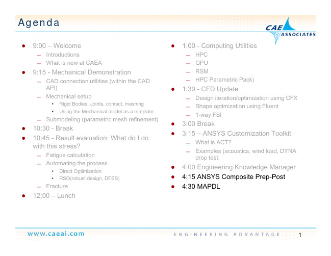
使用Ansys进行工程仿真分析

使用Ansys进行工程仿真分析第一章:Ansys软件的介绍1.1 Ansys软件的背景和起源1.2 Ansys软件的版本和功能特点1.3 Ansys软件的应用范围和行业地位第二章:Ansys工程仿真分析的基本原理2.1 有限元法的基本概念和原理2.2 Ansys软件的有限元分析流程2.3 Ansys软件中的材料模型和加载条件第三章:结构力学仿真分析3.1 结构静力学分析3.1.1 静力学基本方程和边界条件3.1.2 结构应力和应变分析3.1.3 结构变形和位移分析3.2 结构动力学分析3.2.1 结构模态分析3.2.2 结构响应分析3.2.3 结构疲劳分析第四章:流体力学仿真分析4.1 流体静力学分析4.1.1 流体压力和速度场分析4.1.2 流体力学基本方程和边界条件4.1.3 流体流动和压力分析4.2 流体动力学分析4.2.1 流体的稳态和非稳态流动分析4.2.2 流体的湍流模拟和分析4.2.3 流体的热力学和传热分析第五章:热力学仿真分析5.1 热传导分析5.1.1 热传导基本方程和边界条件5.1.2 热传导的定常状态和非定常状态分析5.1.3 热传导的温度场和热通量分析5.2 热辐射分析5.2.1 热辐射的辐射传输方程和边界条件5.2.2 热辐射的辐射通量和辐射能流分析5.2.3 热辐射的温度分布和热辐射热量分析第六章:电磁场仿真分析6.1 静电场分析6.1.1 静电场的基本方程和边界条件6.1.2 静电场的电场强度和电势分布分析6.1.3 静电场的电场力和电场能量分析6.2 磁场分析6.2.1 磁场的基本方程和边界条件6.2.2 磁场的磁感应强度和磁通量密度分析6.2.3 磁场的磁场力和磁场能量分析第七章:Ansys的优势和应用案例7.1 Ansys与传统仿真方法的对比7.2 Ansys在工程领域的应用案例(如航空航天、汽车、电子等)第八章:Ansys的使用技巧和注意事项8.1 Ansys的建模技巧和模型优化方法8.2 Ansys的参数化设计和模型自动化方法8.3 Ansys的结果分析和后处理技巧第九章:Ansys的研发方向和未来发展趋势9.1 Ansys的新功能和技术路线9.2 Ansys的人工智能和大数据分析应用9.3 Ansys在云计算和物联网领域的进展结语:经过对Ansys软件的介绍,结构力学仿真分析、流体力学仿真分析、热力学仿真分析和电磁场仿真分析的详细阐述,以及Ansys 的优势和应用案例、使用技巧和注意事项以及研发方向和未来发展趋势的探讨,我们可以看到Ansys作为一款强大的工程仿真分析软件,在各个领域的工程设计和优化中起到了重要作用,并且具有广阔的市场前景和发展潜力。
复合材料ANSYS ACP仿真教程
— Use internal ACP draping simulation to compute orientation changes due to geometry curvature, develop flat pattern.
— One of ACP(Pre) strengths is that the 2D shell mesh can be extruded into a 3D solid model.
— CAD support: STEP and IGES geometries can be imported to define thick cores or use as guides for 3D extrusions.
Set-up composite material fabric definitions, element orientations, ply layup, etc
Generate Shell Mesh
5
Composite Materials
In Engineering Data, there is now a composite materials library.
with this stress?
— Fatigue calculation — Automating the process
• Direct Optimization • RSO(robust design, DFSS)
— Fracture
12:00 – Lunch
1:00 - Computing Utilities
6
Starting ACP from WB
学会使用ANSYS进行工程仿真分析
学会使用ANSYS进行工程仿真分析第一章:ANSYS工程仿真分析的基础知识ANSYS是目前世界上广泛使用的一种工程仿真分析软件,它可以用于各种不同领域的工程分析和设计。
熟练掌握ANSYS的使用方法对于工程师来说至关重要。
本章将介绍ANSYS的基础知识,包括软件的安装和启动、用户界面的介绍以及基本操作方法等。
首先,安装ANSYS软件是使用它的前提。
用户可以从ANSYS 官方网站上下载安装文件,并按照安装向导的步骤进行安装。
安装完成后,可以通过点击桌面上的图标来启动ANSYS。
启动后,会出现ANSYS的用户界面。
用户界面通常由菜单栏、工具栏、主窗口和命令窗口等组成。
菜单栏上包含了各种功能的菜单,用户可以通过点击菜单来选择所需的功能。
工具栏上则包含了一些常用的工具按钮,可以方便地进行操作。
主窗口用于显示分析结果和编辑模型等。
命令窗口则用于输入命令进行操作,这在一些高级功能中会用到。
在进行工程仿真分析之前,需要先创建一个模型。
ANSYS提供了多种建模工具,例如几何建模工具和计算网格生成工具等。
可以根据需要选择合适的建模工具,并按照提示进行操作。
在建模完成后,可以对模型进行网格生成,即将模型划分为小块,并计算各个小块上的分析参数。
第二章:结构分析结构分析是ANSYS中的一个重要模块,用于对各种结构件进行强度、刚度和模态等分析。
本章将介绍ANSYS中常用的结构分析方法和技巧。
在进行结构分析之前,需要先定义结构的边界条件和加载条件。
边界条件包括约束条件和支撑条件等,而加载条件则包括外力和内力等。
用户可以通过ANSYS提供的工具来定义这些条件,并将其应用于模型中。
在进行结构分析时,可以选择合适的分析方法。
ANSYS提供了多种分析方法,例如静力分析、动力分析和模态分析等。
用户可以根据具体的分析要求选择合适的方法,并设置相应的分析参数。
在进行结构分析时,还可以使用ANSYS的后处理功能来查看分析结果。
后处理功能可以用于绘制应力云图、位移云图和动力响应曲线等。
基于ANSYS ACP的风电机组复合材料机舱罩轻量化设计

收稿日期:2019-09-08 基金项目:国家自然科学基金(51975066);中央高校基本科研业务(106112015CDJXY110006) 作者简介:杜静(1964 -),女,教授,博士,主要从事风力发电方面的研究工作。
第43卷 第3期 2021-03 【105】
式中:[Cij]为刚度矩阵,i,j=1,2,…,6。 假设单层板主轴位于xy平面内,并受到轴向内力, 则上式可以简化为:
目前国内对于复合材料机舱罩的研究多为对现 有设计进行校核,邓树斌等对机舱罩的稳定性进行了 分析[4];宋加佳等利用ABAQUS软件构建了一种基于 ABAQUS的兆瓦级风电机组机舱罩非线性有限元分析仿 真方法[5];李超等从经典层合板理论出发,利用ANSYS 对某兆瓦级风力发电机机舱罩的极限强度进行了计算分
加强筋壁厚/m
12
6
7.5
0.01
0.015
【106】 第43卷 第3期 2021-03
机舱罩为大型壳体结构,采用2D单元进行建模, Ansys中SHELL181是一种具有线性位移特性的有限应 变壳单元,每个单元由4个6自由度节点定义,该单元适 用于复合材料壳体结构分析,且具有良好的收敛性[12]。 CONTACT174与TARGET170单元适用于模拟柔性体-柔 性体之间、刚性体-柔性体的接触,因此用来定义不同 罩体之间、罩体与钢结构之间的接触对,接触状态均设 为绑定接触(bonded always)[13,14]。机舱罩模型如图3 所示。
表3 机舱罩铺层细节
铺层位置 铺层材料顺序 层数 厚度 铺层方向
短切毡300
1
0.4
0/90°
机舱罩
多轴向缝编毡 1250
2
2.4
0/90°
ANSYS ACP复合材料前后处理软件
ANSYS Composite PrepPost Modeling Composites the Simple Way安世亚太科技股份有限公司演讲人:刘程伟复合材料简介ANSYS复合材料分析技术 ACP介绍ACP特色功能ACP新功能复合材料简介ANSYS复合材料分析技术 ACP介绍ACP特色功能ACP新功能•复合材料(Composite materials),是由两种或两种以上不同性质的材料,通过物理或化学的方法,在宏观上组成具有新性能的材料。
•各种材料在性能上取长补短复合材料的分类A.颗粒增强复合材料B.纤维增强复合材料•短纤维增强•长纤维增强复合材料薄片- 由基体和增强体组成的单层结构。
材料属性采用等效的方式。
基体- 一般采用各向同性材料,起到包裹增强体的作用。
纤维增强体- 被基体材料包裹,是复合材料各向异性力学行为的主要原因。
LT叠层组合- 多组复合材料薄片组成,纤维的方向一般不同应用领域•航空航天•风能•运动和娱乐•建筑行业•汽车行业•船舶行业•国防领域•……目录复合材料简介ANSYS复合材料分析技术 ACP介绍ACP特色功能ACP新功能ANSYS 复合材料分析技术•复合材料单元:•Mechanical APDL包含多种复合单元•不同截面属性的3D 梁单元–BEAM188, BEAM189, ELBOW290 elements•2D 轴对称壳单元–SHELL208, SHELL209 elements•3D 铺层壳单元–SHELL181, SHELL281 elements (SHELL131 and SHELL132 are thermal shells)•3D 铺层实体单元–SOLID185, SOLID186, SOLSH190,SOLID278,SOLID279 elementsANSYS 复合材料分析技术•厚度方向仅采用一个单元,模拟复合材料的铺层力学性能–不需要单独的对每层划分网格•可以采用多种失效准则,对复合材料的强度进行评估–最大应变准则–最大应力准则–Tsai-Wu 准则–用户自定义准则•更多的内容参看ANSYS–“Mechanical APDL (formerly ANSYS) > Structural Analysis Guide > Ch. 13 Composites”–“Mechanical APDL (formerly ANSYS) > Structural Analysis Guide > Ch. 16 Beam Analysis and Cross Sections”–“Mechanical APDL (formerly ANSYS) > Structural Analysis Guide > Ch. 17 Shell Analysis and Cross Sections”ET,1,SHELL181! LAYERS PROPERTIESSECTYPE,1,SHELL,,MON_STRATIFIE SECDATA,0.025,1, 0SECDATA,0.500,1, 45SECDATA,0.500,1, -45 SECDATA,0.025,1, 0! ORTHOTROPIC MATERIAL PROPERTIES MP,EX,1,25E6MP,EY,1,1E6MP,EZ,1,1E6MP,GXY,1,5E5MP,GYZ,1,2E5MP,GXZ,1,5E5MP,PRXY,1,0.25MP,PRYZ,1,0.01 SECPLOT,1 (or LAYPLOT command)/PSYMB,ESYS,1THETA = Angle (in degrees) withrespect to element coordinatesystem (ESYS)/ESHAPE,1/EFACET,2EPLOTANSYS 复合材料分析技术目录复合材料简介ANSYS复合材料分析技术 ACP介绍ACP特色功能ACP新功能ANSYS Composite PrepPost介绍ANSYS ACP的主要功能•创建各种形式的复合材料模型•定义复合材料的铺层设置•定义复合材料的纤维方向•对复合材料结构进行评估•评估每层的应力情况•计算复合材料的失效ANSYS ACP分析流程建立几何模型施加边界条件ACP复合材料前处理:铺层信息定义(每层材料属性、厚度、铺层方向角等)ANSYS求解ACP后处理为复合材料加工制作提供必要数据ACP与ANSYS数据传递ANSYS WorkbenchSOLVER定义几何以及边界条件定义铺层信息Write an acp.cdbFileRead the acp.cdbFileImport the results (rstfiles) for postprocessingWrite a *.cdb file withdefined lay-upsLaunch solver其他方式后处理ANSYS Mechanical APDL前处理后处理求解定义材料属性•材料属性的定义同样在ANSYS材料库中进行•定义材料属性的过程中需要考虑纤维的影响•必须的材料属性设置•x, y, z三个方向的杨氏模型•xy, yz, xz三个方向的剪切模量•xy, yz, xz三个方向的泊松比1, x 2, y3, z•失效准则需要定义应力极限值和应变极限值•应力极限值和应变极限值在拉伸和压缩方向一般是不同的应力极限应变极限拉伸X, Y 和 Z 拉伸X, Y 和 Z压缩X, Y 和 Z 压缩X, Y 和 Z剪切XY, YZ 和 XZ 剪切XY, YZ 和 XZ定义材料属性•网格划分过程与普通静力学通用•Mesh中所有的尺寸和选项控制都可以使用•复合材料的建模分析,以面体的网格为起点•ACP同样能够进行实体复合材料的分析•单元集通过Named Selections进行定义•基于Named Selections定义复合材料的铺层•更改几何模型时候需要检查Named Selections的定义单元集Named SelectionsANSYS Composite PrepPost 分析过程•开始复合材料的分析ANSYS Composite PrepPost 界面标准视图模式和视图设置模型树后处理显示设置铺层设置•复合材料铺层设置•采用的纤维层(fabric)•确定需要铺层的位置•铺层的参考方向•增强纤维的方向Static Structural 分析求解ACP (Post) 后处理•失效准则•Max. Strain & Max. Stress •Tsai-Wu•Tsai-Hill•Hashin•Puck•LaRC•Cuntze•Face Sheet Wrinkling•Core Failure•可以在后处理中查看•失效准则•失效模式•关键层•临界载荷步s2t(5) s2t(5)s2t(5)s2t(5)ACP基本功能总结•完全集成于WorkBench平台•直观的创建复合材料铺层•依据制造的过程创建模型•简单高效的修改铺层设置•包含目前通用的失效准则•高效的后处理过程目录复合材料简介ANSYS复合材料分析技术 ACP介绍ACP特色功能ACP新功能Oriented Element Sets利用“方向化单元集”来定义复杂的铺层方向(OES :Oriented Element Sets) the OES normal the OES reference direction the ply angle直观的铺层定义(Build the laminate lay-up)铺层材料铺层方向角铺层数量查看铺层截面,确认铺层正确无误提供复合材料“Draping”功能Draping coefficients提供多种失效模式定义复合材料失效通常有以下两种:●层间失效(由于剪切或拉伸力作用引起)●层内的纤维或基体破坏失效failure patternout-of-phase micro buckling in-phasemicro bucklingshear failurefiber tensionfiber compression fiber ruptureεm > εfmatrix failureεf > εmtransverse crack interfacial failureshear failure with fiber rupture shear w/o fiber rupturematrix tension matrix compressionACP 强大的后处理功能 Agarwal/Broutman (1990) Agarwal/Broutman (1990) delaminationmatrix crack fiber rupturedebondingmicro-buckling / shear failure实体模型•复合材料模型通常是薄壳类结构•壳体厚度方向应力为零实体模型•壳体厚度方向应力不为零•厚度方向应力产生的效果与垂直于纤维方向应力效果相同,很小的应力会造成复合材料的失效•以下情况建议采用实体复合材料模型•多层复合材料•大变形•厚度方向存在载荷•实体模型的分析流程•实体复合材料模型创建过程类似于制造过程。
ANSYS_ACP_Tutorial_ex1复合材料分析官方实例

ACP Tutorial
Define a unidirectional material in ANSYS Workbench Engineering Data with the following properties:
6
© 2013 ANSYS, Inc.
ANSYS, Inc. Proprietary
ACP Tutorial
• Return to ANSYS Project Schematic.
– Update the ACP (Pre) Setup. – Refresh the Section Data. – Update the whole project
1
2
•
19
Updating directly the whole project is also possible.
3
© 2013 ANSYS, Inc.
ANSYS, Inc. Proprietary
ACP Tutorial
• Add the ACP (Pre) component to the existing analysis.
4
© 2013 ANSYS, Inc.
ANSYS, Inc. Proprietary
ACP Tutorial
1. Configure the first ply:
1 2 : select in the tree 3: select ply from the list 4: Angle 0° (default) 5
2. 3.
Define a second ply in the “Sandwich_Core” Ply Group with the Fabric Core and a Ply angle of 0°. Define a third ply in the “Sandwich_Top” Ply Group with the Fabric Carbon T700_UD and a Ply angle of 90°. Set Number of Layers to 3.
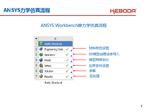
ANSYS力学仿真流程
冲击分析变形最大/最小位置及相应值
20
ANSYS力学仿真流程
冲击分析后处理—应力(Stress)
冲击分析应力最大/最小位置及相应值
21
ANSYS力学仿真流程
随机振动—边界条件设置
随机振动仿真分析需要设置阻尼比Damping Ratio
22
ANSYS力学仿真流程
随机振动—振动曲线Profile输入
随机振动仿真曲线及方向输入
23
ANSYS力学仿真流程
随机振动后处理—变形(Deformation)
随机振动分析变形最大/最小位置及相应值
24
ANSYபைடு நூலகம்力学仿真流程
随机振动后处理—应力(Stress)
随机振动分析应力最大/最小位置及相应值
25
ANSYS力学仿真流程
34
ANSYS力学仿真流程
谐响应谱振动后处理—频域响应(Frequency Response)
谐响应谱振动分析监测点频率-加速度响应曲线及响应值
35
31
ANSYS力学仿真流程
谐响应谱振动—外加激励输入
谐响应谱振动仿真可以增加外力/位移等外加激励输入
32
ANSYS力学仿真流程
谐响应谱振动后处理—变形(Deformation)
谐响应谱振动分析变形最大/最小位置及相应值
33
ANSYS力学仿真流程
谐响应谱振动后处理—应力(Stress)
谐响应谱振动分析应力最大/最小位置及相应值
16
ANSYS力学仿真流程
边界条件设置—模态分析固有频率求解
根据模态分析求解振动曲线范围内的所有固有频率
17
ansys仿真分析演示版.ppt
.,
21
定义属性
为实体模型指定属性
1. 定义所有需要的单元类型,材料, 和实常数.
2. 然后使用 网格工具的“单元属 性” 菜单条 (Preprocessor > MeshTool):
对所有体 (或所有面)一次划分网格, 将优越于 一个一个地划分网格.
通过指定所有线上的份数决定单元的尺寸, 它可以考虑线的曲率, 孔洞的接近程度和其 它特征, 以及单元阶次.
智能网格划分的缺省设置是关闭, 在自由网 格划分时建议采用智能网格划分。 它对映射 网格划分没有影响
.,
28
网格划分
线尺寸
.,
26
网格控制
如图所示为采用不同的 SmartSize尺寸级别进行四 面体网格划分的例子.
高级的 SmartSize 控制, 如 网格扩张和过渡系数在 SMRT 命令 (或
Preprocessor > -Meshing-
Size Cntrls > -SmartSizeAdv Opts...)中提供.
4、梁单元建模时应当注意 截面方位 节点偏移 自由度的
释放
合
5、板单元:不同厚度的板单元连接时注意网格的结点是否重
定义单元属性
在实体模型上直接指定属性将不考虑缺省属性
模型中有多种单元类型, 实常数 和 材料 , 就必须确保给每一
种单元指定了合适的属性
划分网格前对每一个类型的实体分配正确的单元属性
部分常用单元
选择实体类型后按 SET键.
Ansys复合材料结构分析操作指导书---副本

第四章复合材料计算实例在有了前几章知识做铺垫,这一章我们来学习两个复合材料分析的例子,加深复合材料分析的理解,也希望读者能从中收获一些经验。
在这里将第二章的流程图再次拿出来,进一步熟悉ANSYS有限元分析的基本过程。
图7 Ansys 结构分析流程图4.1 层合板受压分析4.1.1 问题描述层合板指的是仅仅由FRP层叠而成的复合板材,中间不包含芯材,板材的性能不仅与纤维的弹性模量、剪切模量有关,还与纤维的铺层方向有着密切关系。
本例中的板材有4层厚度为0.025m的单元板复合而成,单元板的铺层方向为0°、90°、90°、0°,见图13所示。
单元板的材料属性见表4.1。
表 4.1 单元板材料属性EX/MP EY/MP EZ/MP GXY/MP GYZ/MP GXZ/MP PRXY PRYZ PRXZ12.5 300 300 50 20 50 0.25 0.25 0.01图13 复合材料板4.1.2 求解步骤根据问题描述,所要分析的问题为壳体结构的复合材料板,可以采用SOLID46单元建立3D有限元模型进行分析。
结合图7的一般步骤进行分析。
步骤一:选取单元类型,设置单元实常数⑴、在开始一个新分析前,需要指定文件保存路径和文件名。
文件保存路径GUI:【Utility Menu】|【File】|【Change Directory】见图14指定新的文件名GUI:【Utility Menu】|【File】|【Change Jobname】见图15所示图14 指定文件保存路径图15 修改文件名⑵、选取单元类型1)选取单元类型的GUI操作:【Main Menu】|【Preprocessor】|【Element Type】|【Add/Edit/Delete】,执行后弹出Element Types对话框。
2)在Element Types对话框点击Add定义新的单元类型,弹出“Library of Element Types”对话框,见图16所示,按图中所示选择,单元类型参考号输入框中输入数字1。
一步步教你学会使用ANSYS进行工程仿真
一步步教你学会使用ANSYS进行工程仿真Chapter 1: Introduction to ANSYSANSYS is a widely used software in the field of engineering simulation. It offers a comprehensive range of tools for simulation and analysis, allowing engineers to model and solve complex engineering problems. In this chapter, we will provide an overview of ANSYS and its capabilities.1.1 What is ANSYS?ANSYS is a finite element analysis (FEA) software that allows engineers to simulate and analyze the behavior of structures, components, and systems under various conditions. It can be used to predict the response of a design to different loads, temperatures, and other environmental factors. ANSYS is widely used in industries such as aerospace, automotive, civil engineering, and electronics.1.2 ANSYS WorkbenchANSYS Workbench is the platform on which all the solutions provided by ANSYS are built. It provides a user-friendly interface for setting up, solving, and post-processing simulations. ANSYS Workbench integrates various modules and tools, allowing engineers to easily switch between different analysis types and workflows.Chapter 2: Getting Started with ANSYSIn this chapter, we will guide you through the process of installing ANSYS and setting up your first simulation.2.1 InstallationTo get started with ANSYS, you need to download the software from the official ANSYS website. Follow the installation instructions provided by ANSYS to install the software on your computer. Make sure you meet the system requirements specified by ANSYS.2.2 Workflow SetupOnce ANSYS is installed, launch ANSYS Workbench and create a new project. The project is where you will perform all the simulations related to a specific engineering problem. Set up the project by adding the required analysis systems and selecting the appropriate analysis type.Chapter 3: Geometry and MeshingBefore performing an analysis, you need to create the geometry of the system you want to simulate and generate a mesh. In this chapter, we will discuss the tools and techniques available in ANSYS for geometry creation and meshing.3.1 Geometry CreationANSYS provides various tools for creating 3D geometry. You can use the built-in parametric modeling capabilities to create complexshapes or import CAD models from other software. ANSYS also offers a range of tools for modifying and repairing imported CAD models.3.2 Mesh GenerationMeshing is the process of dividing the geometry into a finite number of small elements. ANSYS provides a variety of meshing methods, such as tetrahedral, hexahedral, and polyhedral meshing. The choice of meshing method depends on the type of analysis you are performing and the complexity of the geometry.Chapter 4: Applying Boundary Conditions and Solving the ModelIn this chapter, we will discuss how to apply boundary conditions to your model and solve it using ANSYS.4.1 Applying Loads and ConstraintsANSYS allows you to apply different types of loads and constraints to your model. These can include forces, moments, pressure, temperature, and displacements. You can specify the magnitude, direction, and location of the loads and constraints using the graphical user interface.4.2 Solving the ModelOnce the boundary conditions have been applied, you can solve the model using ANSYS. The solver calculates the response of the system based on the applied loads and constraints. ANSYS offers various solvers, such as the direct solver, iterative solver, and parallel solver.The choice of solver depends on the size of the model and the computational resources available.Chapter 5: Post-Processing and Result AnalysisAfter solving the model, you can analyze and interpret the results using the post-processing tools provided by ANSYS.5.1 Post-ProcessingANSYS offers a wide range of post-processing tools for visualizing and analyzing simulation results. You can generate contour plots, vector plots, animations, and graphs to study the behavior of the model under different conditions. ANSYS also provides tools for calculating derived quantities, such as stresses, strains, displacements, and temperatures.5.2 Result AnalysisOnce you have obtained the simulation results, you can analyze and interpret them to gain insights into the behavior of the system. ANSYS allows you to compare different designs, perform sensitivity analysis, and optimize the performance of your model.Chapter 6: Advanced Topics in ANSYSIn this chapter, we will cover some advanced topics in ANSYS, such as parametric analysis, optimization, and multiphysics simulations.6.1 Parametric AnalysisParametric analysis allows you to study the behavior of a design under different input parameters. ANSYS provides tools for creating design tables and performing automated parametric simulations. This can help you optimize your design and understand its robustness to variation in input parameters.6.2 OptimizationANSYS offers optimization tools that allow you to automatically search for the best design based on predefined objectives and constraints. You can define design variables, objective functions, and constraints, and let ANSYS explore the design space to find the optimal solution.6.3 Multiphysics SimulationsANSYS supports simulations involving multiple physical phenomena, such as fluid-structure interaction, thermal-structural coupling, and electromagnetic-thermal coupling. You can couple different analysis modules together to simulate complex engineering problems that involve multiple physics.ConclusionIn this article, we have provided a step-by-step guide on how to use ANSYS for engineering simulation. We covered various aspects of ANSYS, such as its capabilities, installation, geometry, meshing, boundary conditions, solving, post-processing, and advanced topics. Byfollowing this guide, you should be able to get started with ANSYS and perform simulations for a wide range of engineering applications.。
ANSYS-Composite-acp-16.0-Release

Enhanced Unit System Handling for Composite WB Projects
• User can now freely choose unit system in ACP • ACP remembers the last unit system used (same logic as Mechanical)
Elasticity and Strength properties interpolated based on local shear, temperature, and degradation factor → make use of wide materials characterization!
Look-up Table Plots
Unit System
Solution Selection
3D Interaction
Shared Licencing
Integration in ANSYS Installer
Conversion of Legacy Models
Progressive Damage Postprocessing
14 © 2013 ANSYS, Inc. June 26, 2015
A Simple Example – Inverse Reserve Factor
Load Case: 14’000RPM, Δp = 10kPa
No fields applied
Degradation and draping active
• Material handling for drop-offs:
• Global (default) • Custom per fabric/stackup
ANSYS Composite PrepPost
The OES 参照方向
● ACP提供了丰富的复合材料失效准则: - 失效模式无关的失效准则 最大应力准则 最大应变准则 - 多项式失效模式准则 Tsai-Hill准则 Tsai-Wu准则 - 失效模式相关的失效准则 Hashin准则 Puck准则 LaRC准则
铺层方向角 失效准则定义
ANSYS Composite PrepPost
ANSYS Composite PrepPost
——复合材料专用前/后处理工具
机械分析
ANSYS Composite PrepPost
产品概述
复合材料是由两种或两种以上具有不同性质的材料粘合而成具有新性能的一 种材料。在工程应用中,由于复合材料具有很高的比刚度(刚度与重量之比)和柔 韧性而广受制造业的亲睐。
重庆分公司 电话:86-23-63106775 传真:86-23-63106773
济南分公司 电话:86-31-86072996 传真:86-31-85180808
广州分公司
电话: 86-20-38102018 传真: 86-20-38102010
武汉分公司
电话: 86-27-87259015/6/7 传真:86-27-87259015/6/7-168
西安分公司
电话: 86-29-88348317 传真: 86-29-88348275
香港分公司
电话:00852-31139711 传真:00852-31139710
模型的整体结果
失效准则结果显示
● ACP还提供了“Draping and flat-wrap”功能,针对分析结果可以对复合材料进行“覆盖-展开”操作,这将非常有 利于复合材料的加工制造。
Draping and flat-wrap
ANSYS和ADAMS柔性仿真详细步骤

ANSYS和ADAMS柔性仿真详细步骤ANSLY柔性仿真步骤:1.确定仿真目标:首先要确定柔性仿真的目标,例如想要分析材料的应力应变分布、模拟结构在不同环境下的响应等。
2.创建模型:根据仿真目标,使用ANSYS中的建模工具创建模型。
可以通过几何建模、导入CAD文件等方式创建模型。
模型应包括几何形状、材料属性和约束条件等。
3.定义材料属性:根据实际情况,可以通过ANSYS中的材料库选择合适的材料属性,或者根据具体材料的性质自定义材料属性。
材料属性包括材料的弹性模量、泊松比、密度等。
4.定义约束条件:确定模型中哪些部分是固定的或者受到限制的。
通过在模型上设置约束条件,可以模拟实际物体的固定边界条件。
5.定义加载条件:根据仿真目标,在模型上定义加载条件,即施加在模型上的外部力或者压力。
可以通过指定点载荷、面载荷等方式定义加载条件。
6.网格划分:在模型上进行网格划分,将模型离散为有限个较小的单元。
较精细的网格划分可以提高仿真的精确性,但同时也会增加计算量。
7.选择求解器和求解参数:ANSYS中有多种求解器可以选择,不同的求解器适用于不同类型的仿真问题。
根据自己的仿真目标选择合适的求解器,并设置求解参数,如收敛准则、时间步长等。
8.进行仿真计算:根据以上步骤的设置,启动计算。
ANLSYS会根据模型、材料属性、加载条件等信息进行计算,并生成仿真结果。
对仿真结果进行处理和分析。
如可以分析材料的应力应变分布、变形情况、模态分析等。
ADAMS柔性仿真步骤:1.确定仿真目标:和ANSYS一样,首先要确定柔性仿真的目标,例如想要分析柔性结构的变形、模拟柔性机构的运动等。
2.创建模型:使用ADAMS中的建模工具创建模型。
ADAMS提供了丰富的建模功能,可以创建刚体和柔性体,并定义它们之间的关系和约束。
3.定义材料属性:在ADAMS中,柔性体的材料属性可以通过定义材料的弹性模量、泊松比、密度等参数来实现。
4.确定刚体和柔性体之间的连接关系:根据模型的实际情况,在模型中定义刚体和柔性体之间的连接关系。
ANSYS复合材料仿真分析
在ANSYS 中可以定义多种材料属性:主菜单-> preprocesser -> Material Prop -> Material Models -> 打开Define Material Model Behavior 对话框-> 顶部菜单中:Material -> New Model ... -> 弹出Define Material ID 对话框-> 定义更多的材料ANSYS复合材料仿真分析2009-05-23 23:31复合材料,是由两种或两种以上性质不同的材料组成。
主要组分是增强材料和基体材料。
复合材料不仅保持了增强材料和基体材料本身的优点,而且通过各相组分性能的互补和关联,获得优异的性能。
复合材料具有比强度大、比刚度高、抗疲劳性能好、各向异性、以及材料性能可设计的特点,应用于航空领域中,可以获得显著的减重效益,并改善结构性能。
目前,复合材料技术已成为影响飞机发展的关键技术之一,逐渐应用于飞机等结构的主承力构件中,西方先进战斗机上复合材料使用量已达结构总重量的25%以上。
飞机结构中,复合材料最常见的结构形式有板壳、实体、夹层、杆梁等结构。
板壳结构如机翼蒙皮,实体结构如结构连接件,夹层结构如某些薄翼型和楔型结构,杆梁结构如梁、肋、壁板。
此外,采用缠绕工艺制造的筒身结构也可视为层合结构的一种形式。
一.复合材料设计分析与有限元方法复合材料层合结构的设计,就是对铺层层数、铺层厚度及铺层角的设计。
采用传统的等代设计(等刚度、等强度)、准网络设计等设计方法,复合材料的优异性能难以充分发挥。
在复合材料结构分析中,已经广泛采用有限元数值仿真分析,其基本原理在本质上与各向同性材料相同,只是离散方法和本构矩阵不同。
复合材料有限元法中的离散化是双重的,包括了对结构的离散和每一铺层的离散。
这样的离散可以使铺层的力学性能、铺层方向、铺层形式直接体现在刚度矩阵中。
有限元分析软件,均把增强材料和基体复合在一起,讨论结构的宏观力学行为,因此可以忽略复合材料的多相性导致的微观力学行为,以每一铺层为分析单元。
ANSYS命令流学习笔记14-shell单元的铺层复合材料分析

!ANSYS命令流学习笔记 14-shell 单元的铺层复合材料分析!学习重点:!1、熟悉复合材料的材料特点工程应用中典型的复合材料为纤维增强复合材料。
玻璃纤维增强塑料(玻璃钢)、碳纤维、石墨纤维、硼纤维等高强度和高模量纤维。
复合材料各层为正交各向异性材料(O rthotropic )或者横向各向异性材料( Transversal Isotropic),材料的性能与材料主轴的取向有关。
各向异性 Anisotropic,一般的各项同性材料需要两个材料参数弹性模量而各向异性在 XYZ有着不同的材料属性,而且拉伸行为和剪切行为互相关联。
程需要 21 个参数。
E 和泊松比v。
定义其几何方正交各向异性 orthotropic,在XYZ有着不同的材料属性,而且拉伸行为和剪切行为无关,定义材料需要 9 个参数: Ex, Ey, Ez, Vxy, Vyz,Vxz, Gxy, Gyz, Gxz。
横向各向异性 Transversal Isotropic,属于各向异性材料,但是在某个平面上表现出二维上的各向同性。
!2、熟悉复合材料分析所用的ANSYS单元复合材料单元关键在于能够实现铺层。
不同截面属性的梁单元(beam188, beam189, elbow290 ),2D 对称壳单元( shell208, shell209 ),3D 铺层壳单元( shell181, shell281, shell131, shell132),3D 铺层实体单元( solid185, solid186, solsh190, solid278, solid279 ),均能实现复合材料的搭建。
其中Beam 单元和2D 对称壳单元很少使用。
SHELL91、 SHELL99、 SOLID46、SOLID191 用于一些以前的分析教程中,但是现在这些单元已经被淘汰,最好选择下列单元区替代他们。
用越来越少的单元做越来越多的事情也是趋势。
Shell208 和 shell209, 2D 对称壳单元前者为 2 节点 3 自由度单元,后者为 3 节点 3 自由度单元,均能用于薄板和中厚板结构(L/h > 5-8 )。
Ansys ACP_Tutorial_Ex2实例2
2
© 2013 ANSYS, Inc.
ANSYS, Inc. Proprietary
A: Modify mesh and lay-up
• At the end of the Tutorial 1, the critical failure mode was matrix failure in one layer of the top face sheet which consists of three UD plies with equal orientation.
15
© 2013 ANSYS, Inc.
ANSYS, Inc. Proprietary
End of Tutorial 2 Thank you
16
© 2013 ANSYS, Inc.
ANSYS, Inc. Proprietary
6
© 2013 ANSYS, Inc.
ANSYS, Inc. Proprietary
B: Create Edge Set and a Tube Selection Rule for a new ply
• Create an Edge Set derived from an Element Set:
• Add a new ply to reinforce the edge:
9
© 2013 ANSYS, Inc.
ANSYS, Inc. Proprietary
C: Taper Edge for Core
• Modify the core:
• Thickness distribution of this ply:
• The goal is to optimize the layup to increase the strength of the composite structure. First, the 3 UD plies will be replaced and a refined mesh will provide more accurate results.
航空用复合材料层合结构ANSYS有限元分析

复合材料的优势
层合结构的特点
层合结构是复合材料的一种重要形式, 通过将不同材料层层叠加形成,具有 各向异性的特点,对其进行分析需要 采用有限元方法。
复合材料具有高强度、轻质、抗疲劳 等优点,能够显著提高航空器的性能 和安全性。
目的和意义
目的
通过对航空用复合材料层合结构进行 ANSYS有限元分析,探究其力学性 能和损伤演化规律,为优化设计和安 全评估提供依据。
意义
有限元分析能够准确模拟层合结构的 复杂应力分布和变形行为,有助于提 高航空器的结构效率和安全性,对于 推动航空工业的发展具有重要意义。
02
航空复合材料层合结构概述
复合材料的定义和分类
定义
复合材料是由两种或两种以上材 料组成的一种材料,其性能取决 于各个组成材料的性质以及它们 的组合方式。
分类
软件概述
01
全球知名的工程仿真软件
02
提供多物理场仿真能力
支持多种操作系统平台
03
功能模块
前处理模块
支持复杂模型的建立和网 格划分
求解模块
进行各种物理场的仿真计 算
后处理模块
提供丰富的可视化功能和 结果分析工具
在复合材料分析中的应用
高效模拟复合材料的力学 行为
预测复合材料的损伤和破 坏行为
考虑材料的非均匀性和各 向异性
优化设计和改进建议
要点一
总结词
基于有限元分析结果,可以提出优化设计和改进建议。
要点二
详细描述
根据应力和应变分布以及损伤和破坏模式的分析结果,我 们可以提出一系列优化设计和改进建议。例如,可以调整 复合材料的层合顺序、改变连接方式或增加加强筋等措施 来改善结构的力学性能。同时,还可以通过优化工艺参数 和选择合适的材料来提高复合材料的质量和可靠性。这些 建议有助于提高航空用复合材料层合结构的安全性和可靠 性。
- 1、下载文档前请自行甄别文档内容的完整性,平台不提供额外的编辑、内容补充、找答案等附加服务。
- 2、"仅部分预览"的文档,不可在线预览部分如存在完整性等问题,可反馈申请退款(可完整预览的文档不适用该条件!)。
- 3、如文档侵犯您的权益,请联系客服反馈,我们会尽快为您处理(人工客服工作时间:9:00-18:30)。
Thru‐Thickness ILS & ILN Stress Plots – Shells
12
Post-processing of Composite Results
Sandwich Construction Post-processing.
— Wrinkling
• Local buckling of a face sheet under compression • Failure indicator available using shell modeling of sandwich
Example below shows parametric changes of doubler width shown in red.
10
Post-processing of Composite Results
Efficient post-processing of composite-specific results quantities. New Sampling Element post-processing.
— One of ACP(Pre) strengths is that the 2D shell mesh can be extruded into a 3D solid model.
— CAD support: STEP and IGES geometries can be imported to define thick cores or use as guides for 3D extrusions.
6
Starting ACP from WB
Once shell mesh is generated and materials defined, ACP can be started by right cg and Post-processing
Once the model is setup in APC(Pre) it can be linked to whatever type of analyses you need to solve:
— ANSYS Composite PrepPost can predict these base on the work of Roos, Kress, & Ermanni
Critical Stresses in Bend
Thru‐Thickness ILS & ILN Stress Plots – Solids
orientations)
— Define the element orientation (so as to properly orient materials)
— Define the ply sequence for groups of elements (usually corresponding to faces of the geometry)
— Interface with Vistagy’s FiberSim. — Modify the fiber orientation to something that is actually observed on the
manufacturing floor through alignment with local rosettes.
— Core Failure
• Local failure of core in shear or tensile loading • Failure indicator available using shell modeling of sandwich
13
Advanced ACP Capabilities
Set-up composite material fabric definitions, element orientations, ply layup, etc
Generate Shell Mesh
5
Composite Materials
In Engineering Data, there is now a composite materials library.
9
Parametric Modeling of Composites
Since ACP is integrated into Workbench, the composite data from ACP will be updated with any parameter changes in WB.
— Plot worst case failure criteria over all layers. — Pick element and see stress/strain and failure through the thickness
11
Post-processing of Composite Results
Agenda
9:00 – Welcome
— Introductions — What is new at CAEA
9:15 - Mechanical Demonstration
— CAD connection utilities (within the CAD API)
— Mechanical setup
ANSYS v14.5 Update Seminar
CAE Associates Inc. and ANSYS Inc. Proprietary © 2013 CAE Associates Inc. and ANSYS Inc. All rights reserved.
ACP Background
Show Libraries
Material does not need to be assigned to bodies in Mechanical. Material assignment is done in ACP.
All materials in Engineering Data are brought into ACP.
— Meshing shell geometry, applying loads and boundary conditions.
— Can be in ANSYS Mechanical or Mechanical APDL — Define materials (Engineering Data, or APDL)
Solve the model - computed by the standard ANSYS solver, in batch mode.
Post-process the results in ACP: deformations, thicknesses and failure criteria.
• Rigid Bodies, Joints, contact, meshing • Using the Mechanical model as a template.
— Submodeling (parametric mesh refinement)
10:30 - Break 10:45 - Result evaluation: What do I do
— R14 Improved solid model extrusion, transitioning, and drop-off capabilities
Make thru-thickness stress plots and account for interlaminar normal stresses with shells.
— Traditional shell approaches can not account for interlaminar normal stress (shown in blue curve)
Fiber orientation prediction and modification.
— Use internal ACP draping simulation to compute orientation changes due to geometry curvature, develop flat pattern.
14
Advanced ACP Capabilities
3D Solid Modeling:
— If a composite part is thick and bulky a shell mesh may not be sufficient to predict accurate results.
— HPC — GPU — RSM — HPC Parametric Pack)
1:30 - CFD Update
— Design iteration/optimization using CFX — Shape optimization using Fluent — 1-way FSI
3:00 Break 3:15 – ANSYS Customization Toolkit
Then connect ACP(Post) to the Solution of that analysis.
8
ACP Modeling Capabilities
Multiple oriented element sets allow for multi-laminate build-up.
4
Incorporation into WB Architecture
Starting with v14.0 ACP is incorporated directly into the WB architecture.
Define composite material properties
