TCL TCM 三轴气缸
真空用气缸 ZCUK
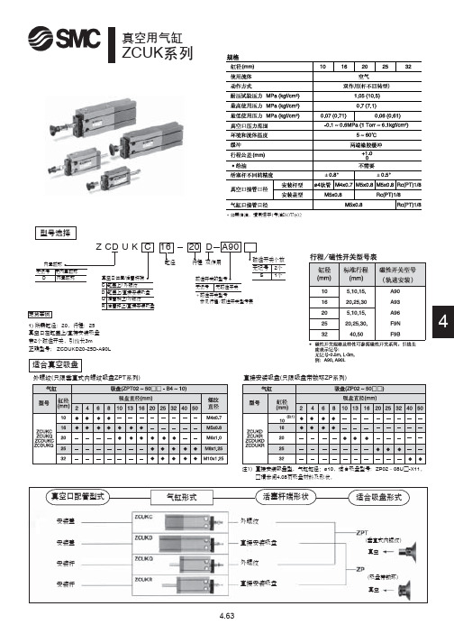
ZCUK系列
*如需给油,请用透平1号油ISOVG32
型号选择
Z CD U K C 16 20 D A90
内置磁环 无记号 无内置磁环
D 内置磁环
定货举例
真空口位置/活塞杆端 C 缸盖上/ 外螺纹 D 缸盖上/直接安装吸盘 Q 活塞杆上/外螺纹 R 活塞杆上/直接安装吸盘
1) 所需缸径:20,行程:25 真空口在缸盖上/直接安装吸盘 带2个磁性开关,引线长3m 正确型号; ZCDUKD20-25D-A90L
行程
真空口径
通孔 ø1.5
气缸口径 行程
通孔 深5 沉孔
行程 行程
磁性开关 行程
通孔 深5 沉孔
行程 行程
磁性开关 行程
外螺纹/ZC□UKC16~32
密封垫
通孔
气缸口径
直接安装吸盘/ZC □UKD16~32
通孔
气缸口径
4
行程
行程真空口径Leabharlann 通孔 通孔通孔 沉孔
行程 行程
磁性开关 行程
通孔 沉孔
行程 行程
密封垫
通孔
磁性开关
ød通孔
真空口径
通孔 深5 沉孔
行程 行程
磁性开关 行程
ø1.5通孔
磁性开关
通孔 深5 沉孔 行程
行程
行程
直接安装吸盘/ZC□UKR16~32
通孔
气缸口径
4
ød通孔
真空口径 接管座(只限ø16)
通孔 深5沉孔
行程 行程
磁性开关 行程
六角对边宽8
4.65
缸径
行程 双作用
磁性开关个数 无记号 2个
磁性开关的型号
S 1个
Universal NC9系列中等功率预加润neumatic气缸说明书
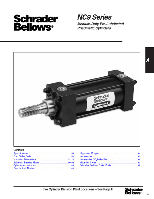
For Cylinder Division Plant Locations – See Page II.ANC9 SeriesMedium-Duty Pre-LubricatedPneumatic CylindersContentsSpecifications (52)Ford Order Code (53)Mounting Dimensions.................................................54-79 Spherical Bearing Mount............................................80-81 Cylinder Accessories. (82)Double Rod Models.........................................................83Alignment Coupler.. (84)Accessories (85)Accessories / Cylinder Kits (86)Mounting Styles (87)Schrader Bellows Order Code (88)51NC9 Series Pneumatic Cylinders52For additional information – call your localSchrader Bellows Distributor.General SpecificationsNC9 SeriesPneumatic Cylinders53For Cylinder Division Plant Locations – See Page II.AOrdering InformationNC9 Series Pneumatic Cylinders54For additional information – call your localSchrader Bellows Distributor.Side Lug Mount1-1/2" to 6" Bore SizesNC9 SeriesPneumatic Cylinders55For Cylinder Division Plant Locations – See Page II.ASide Lug Mount1-1/2" to 6" Bore SizesNC9 Series Pneumatic Cylinders56For additional information – call your localSchrader Bellows Distributor.Side Tap Mount1-1/2" to 6" Bore SizesNC9 SeriesPneumatic Cylinders57For Cylinder Division Plant Locations – See Page II.47/851/4415/1659/1655/1651/16515/1657/16511/16665/861/461/2667/861/461/265/865/1673/1669/16613/16615/1673/1673/1671/16711/1675/1677/16711/16711/16711/16Rod Style Style +.000Dia. 4 & 5 2 & 3-.002Bore MMLL KKAACB C D NA V VA VB W WF XT Y NDZB5/815/813/815/813/4113/81213/813/4121/213/813/42131/213/813/4221/2313/8413/4221/2331/2115/1625/16115/1629/1625/16115/16213/1625/1629/1627/1631/16211/16215/1627/1635/16211/16215/1631/1627/1635/16211/16215/1631/1635/1635/16213/1637/1631/1633/1637/1637/1637/165/87/811/411/221/16211/1631/44441/847/847/851/853/4Side Tap Mount1-1/2" to 6" Bore SizesBore E NPTF SAEFG J KNTTNLB LG P SN 11/2221/231/4456221/2333/441/251/261/23/8†3/8†3/8†1/21/21/23/43/83/83/85/85/85/83/411/211/211/213/413/413/4211111/411/411/411/21/45/165/163/83/87/167/16†On 11/2", 2" and 21/2" bore sizes, the head-end (only) pipe thread is not full depth on cylinders with maximum oversize rods. Minimum of three full threads available.**Port adapter fitting furnished at head end only.Table 1—Envelope and Mounting DimensionsTable 2—Rod Dimensions and Envelope Dimensions Affected by Rod Size1.1241.4991.1241.9991.4991.1242.3741.4991.9991.4992.6241.9992.3741.4993.1241.9992.3742.6241.4994.2491.9992.3742.6243.1243.7491.9994.7492.3742.6243.1243.7494.2493/411/83/415/811/83/4211/815/811/821/415/8211/8315/8221/411/831/215/8221/4331/215/84221/4331/231/23/81/23/85/81/23/83/41/25/81/27/85/83/41/215/83/47/81/215/83/47/8115/813/47/81111/27/81/211/87/81/211/27/811/87/8111/1611/811/27/821/1611/811/2111/167/8311/811/2111/1621/1625/811/833/811/2111/1621/1625/837/16-203/4-167/16-201-143/4-167/16-2011/4-123/4-161-143/4-1611/2-121-1411/4-123/4-1617/8-121-1411/4-1211/2-123/4-1621/2-121-1411/4-1211/2-1217/8-1221/4-121-143-1211/4-1211/2-1217/8-1221/4-1221/2-129/1615/169/1615/1615/169/16111/1615/1615/1615/16115/1615/16111/1615/1623/815/16111/16115/1615/1633/815/16111/16115/1623/827/815/1637/8111/16115/1623/827/833/81/2-207/8-141/2-2011/4-127/8-141/2-2011/2-127/8-1411/4-127/8-1413/4-1211/4-1211/2-127/8-1421/4-1211/4-1211/2-1213/4-127/8-1431/4-1211/4-1211/2-1213/4-1221/4-1223/4-1211/4-1233/4-1211/2-1213/4-1221/4-1223/4-1231/4-12Thread Rod Extensions and Envelope Dimensions Affected By Rod Size 115/1625/16113/1629/1625/16115/16213/1625/1629/1627/1631/16211/16215/1627/1635/16211/16215/1631/1627/1635/16211/16215/1631/1635/1635/16213/1637/1631/1633/1637/1637/1637/16–1/2–5/8––3/4–5/8––––––––––5/8––––5/8–1/2–––1/21/21/4–1/4–1/41/4–1/4–1/41/41/41/41/41/41/41/41/41/4–1/41/41/41/4–1/4–1/41/41/4––3/16–3/16–3/83/16–3/8–3/89/161/29/163/811/161/29/169/163/8–1/29/169/1611/16–7/16–9/169/1611/16–––1–11/4––11/2–11/4––––––––––15/8––––15/8–11/2–––11/211/21–1–13/81–13/8–13/8215/817/813/821/415/817/8213/8–15/817/8221/4–15/8–17/8221/4––11/2221/231/44563/83/811/3211/3211/327/167/167/167/161/21/21/21/25/85/85/85/85/83/43/43/43/43/43/43/47/87/87/87/87/87/87/835/835/833/441/441/441/2521/421/423/825/825/827/831/821/421/423/825/825/827/831/81/4-205/16-183/8-161/2-131/2-135/8-113/4-10Add StrokeAdd Stroke#6**#6#6#10#10#10#1211/817/811/821/217/811/8317/821/217/831/221/2317/841/221/2331/217/8–21/2331/241/2–21/2–331/241/2––EENC9 Series Pneumatic Cylinders58For additional information – call your localSchrader Bellows Distributor.Head Rectangular Flange Mountand Cap Rectangular Flange Mount1-1/2" to 6" Bore SizesNC9 SeriesPneumatic Cylinders59For Cylinder Division Plant Locations – See Page II.5/815/813/815/813/4113/81213/813/4121/213/813/42131/213/813/4221/2313/8413/4221/2331/211/2221/231/445645/8545/851/4543/455/851/853/855/861/457/861/855/861/257/861/861/457/863/461/863/861/263/463/465/871/467/8771/471/471/4Rod Style Style +.000Dia. 4 & 5 2 & 3-.002Bore MMLL KKAAC B C D NA V VA VB W WF Y XF ZB ZF23/433/837/8411/1657/1665/875/8Bore E NPTF SAEFFBG J KR TF UF LB LG P11/2221/231/4456Table 1—Envelope and Mounting Dimensions†On 11/2", 2" and 21/2" bore sizes, the head-end (only) pipe thread is not full depth on cylinderswith maximum oversize rods. Minimum of three full threads available.**Port adapter fitting furnished at head end only.221/2333/441/251/261/23/8†3/8†3/8†1/21/21/23/43/83/83/85/85/85/83/411111/411/411/411/21/45/165/163/83/87/167/1611/211/211/213/413/413/425/163/83/87/167/169/169/164441/8––51/853/4Table 2—Rod Dimensions and Envelope Dimensions Affected by Rod Size1.1241.4991.1241.9991.4991.1242.3741.4991.9991.4992.6241.9992.3741.4993.1241.9992.3742.6241.4994.2491.9992.3742.6243.1243.7491.9994.7492.3742.6243.1243.7494.2493/411/83/415/811/83/4211/815/811/821/415/8211/8315/8221/411/831/215/8221/4331/215/84221/4331/231/23/81/23/85/81/23/83/41/25/81/27/85/83/41/215/83/47/81/215/83/47/8115/813/47/81111/27/81/211/87/81/211/27/811/87/8111/1611/811/27/821/1611/811/2111/167/8311/811/2111/1621/1625/811/833/811/2111/1621/1625/837/16-203/4-167/16-201-143/4-167/16-2011/4-123/4-161-143/4-1611/2-121-1411/4-123/4-1617/8-121-1411/4-1211/2-123/4-1621/2-121-1411/4-1211/2-1217/8-1221/4-121-143-1211/4-1211/2-1217/8-1221/4-1221/2-129/1615/169/1615/1615/169/16111/1615/1615/1615/16115/1615/16111/1615/1623/815/16111/16115/1615/1633/815/16111/16115/1623/827/815/1637/8111/16115/1623/827/833/81/2-207/8-141/2-2011/4-127/8-141/2-2011/2-127/8-1411/4-127/8-1413/4-1211/4-1211/2-127/8-1421/4-1211/4-1211/2-1213/4-127/8-1431/4-1211/4-1211/2-1213/4-1221/4-1223/4-1211/4-1233/4-1211/2-1213/4-1221/4-1223/4-1231/4-12Thread Rod Extensions and Envelope Dimensions Affected By Rod Size–1/2–5/8––3/4–5/8––––––––––5/8––––5/8–1/2–––1/21/21/4–1/4–1/41/4–1/4–1/41/41/41/41/41/41/41/41/41/4–1/41/41/41/4–1/4–1/41/41/4––3/16–3/16–3/83/16–3/8–3/89/161/29/163/811/161/29/169/163/8–1/29/169/1611/16–7/16–9/169/1611/16–––1–11/4––11/2–11/4––––––––––15/8––––15/8–11/2–––11/211/21–1–13/81–13/8–13/8215/817/813/821/415/817/8213/8–15/817/8221/4–15/8–17/8221/4––1.431.842.192.763.324.104.8821/421/423/825/825/827/831/833/841/845/851/261/475/885/835/835/833/441/441/441/25115/1625/16115/1629/1625/16115/16213/1625/1629/1627/1631/16211/16215/1627/1635/16211/16215/1631/1627/1635/16211/16215/1631/1635/1635/16213/1637/1631/1633/1637/1637/1637/16553/8555/853/851/8651/253/461/467/861/263/461/471/861/263/467/861/273/863/4771/873/873/873/8875/873/4888Add StrokeAdd Stroke 47/851/4415/1659/1659/1651/16515/1657/16511/1655/8665/861/461/2661/461/265/865/1673/1669/16613/16615/1673/1673/1671/16711/1675/1677/16711/16711/16711/16#6**#6#6#10#10#10#1211/817/811/821/217/811/8317/821/217/831/221/2317/841/221/2331/217/8–21/2331/241/2–21/2–331/241/2––Head Rectangular Flange Mountand Cap Rectangular Flange Mount 1-1/2" to 6" Bore SizesEENC9 Series Pneumatic Cylinders60For additional information – call your localSchrader Bellows Distributor.Head Square Flange Mount andCap Square Flange Mount1-1/2" to 6" Bore SizesNC9 SeriesPneumatic Cylinders61For Cylinder Division Plant Locations – See Page II.5/815/813/815/813/4113/81213/813/4121/213/813/42131/213/813/4221/2313/8413/4221/2331/247/851/4415/1659/1655/1651/16515/1657/16511/16665/861/461/2667/861/461/265/865/1673/1669/16613/16615/1673/1673/1671/16711/1675/1677/16711/16711/16711/16Rod Style Style +.000Dia. 4 & 5 2 & 3-.002Bore MMLL KKAACBCDNAVVAVBWWFYZBZF115/1625/16115/1629/1625/16115/16213/1625/1629/1627/1631/16211/16215/1627/1635/16211/16215/1631/1627/1635/16211/16215/1631/1635/1635/16213/1637/1631/1633/1637/1637/1637/1633/841/845/851/261/475/885/8 Bore E NPTF SAEFFBG J KR TF UF LB LG P Head Square Flange Mount andCap Square Flange Mount 1-1/2" to 6" Bore SizesTable 1—Envelope and Mounting Dimensions1.1241.4991.1241.9991.4991.1242.3741.4991.9991.4992.6241.9992.3741.4993.1241.9992.3742.6241.4994.2491.9992.3742.6243.1243.7491.9994.7492.3742.6243.1243.7494.2493/411/83/415/811/83/4211/815/811/821/415/8211/8315/8221/411/831/215/8221/4331/215/84221/4331/231/23/81/23/85/81/23/83/41/25/81/27/85/83/41/215/83/47/81/215/83/47/8115/813/47/81111/27/81/211/87/81/211/27/811/87/8111/1611/811/27/821/1611/811/2111/167/8311/811/2111/1621/1625/811/833/811/2111/1621/1625/837/16-203/4-167/16-201-143/4-167/16-2011/4-123/4-161-143/4-1611/2-121-1411/4-123/4-1617/8-121-1411/4-1211/2-123/4-1621/2-121-1411/4-1211/2-1217/8-1221/4-121-143-1211/4-1211/2-1217/8-1221/4-1221/2-129/1615/169/1615/1615/169/16111/1615/1615/1615/16115/1615/16111/1615/1623/815/16111/16115/1615/1633/815/16111/16115/1623/827/815/1637/8111/16115/1623/827/833/81/2-207/8-141/2-2011/4-127/8-141/2-2011/2-127/8-1411/4-127/8-1413/4-1211/4-1211/2-127/8-1421/4-1211/4-1211/2-1213/4-127/8-1431/4-1211/4-1211/2-1213/4-1221/4-1223/4-1211/4-1233/4-1211/2-1213/4-1221/4-1223/4-1231/4-12Thread Rod Extensions and Envelope Dimensions Affected By Rod Size1/4**1/21/4**5/81/2**1/4**3/41/2**5/81/4**1/2**3/8**1/2**1/4**5/8**3/8**1/2**1/2**1/4**5/83/8**1/2**1/2**5/8**5/81/43/83/8**1/2**1/2**1/21/21/4–1/4–1/41/4–1/4–1/41/41/41/41/41/41/41/41/41/4–1/41/41/41/4–1/4–1/41/41/4––3/16–3/16–3/83/16–3/8–3/89/161/29/163/811/161/29/169/163/8–1/29/169/1611/16–7/16–9/169/1611/16––1/415/811/415/811/2111/43/413/8111/43/415/8111/413/83/415/8111/413/815/815/87/811/211/811/411/211/211/21–1–13/81–13/8–13/8215/817/813/821/415/817/8213/8–15/817/8221/4–15/8–17/8221/4––11/2221/231/4456553/8555/853/851/8651/253/461/467/861/263/461/471/861/263/467/861/273/863/4771/873/873/873/8875/873/488823/433/837/8411/1657/1665/875/811/2221/231/4456221/2333/441/251/261/23/8†3/8†3/8†1/21/21/23/43/83/83/85/85/85/83/411111/411/411/411/21/45/165/163/83/87/167/1611/211/211/213/413/413/425/163/83/87/167/169/169/164441/847/847/851/853/41.431.842.192.763.324.104.8821/421/423/825/825/827/831/835/835/833/441/441/441/25†On 11/2", 2" and 21/2" bore sizes, the head-end (only) pipe thread is not full depth on cylinders with maximum oversize rods. Minimum of three full threads available.**Port adapter fitting furnished at head end only.Table 2—Rod End Dimensions and Envelope Dimensions Affected By Rod Size**For all MF5 mounts and MF6 mounts with maximum oversized rods.Add StrokeAdd Stroke#6**#6#6#10#10#10#1211/817/811/821/217/811/8317/821/217/831/221/2317/841/221/2331/217/8–21/2331/241/2–21/2–331/241/2––EENC9 Series Pneumatic Cylinders62For additional information – call your localSchrader Bellows Distributor.Tie Rods Extended Mountings1-1/2" to 6" Bore SizesNC9 SeriesPneumatic Cylinders63For Cylinder Division Plant Locations – See Page II.5/815/813/815/813/4113/81213/813/4121/213/813/42131/213/813/4221/2313/8413/4221/2331/21.968–1.968–2.4681.968–2.468–2.4683.7352.9683.7352.4684.3122.9683.7353.7352.468–2.9683.7353.7355.000–2.968–3.6253.7354.312––47/851/4415/1659/1655/1651/16515/1657/16511/16665/861/461/2667/861/461/265/865/1673/1669/16613/16615/1673/1673/1671/16711/1675/1677/16711/16711/16711/1621/421/423/825/825/827/831/8Tie Rods Extended Mountings1-1/2" to 6" Bore SizesRod Style Style +.000Dia. 4 & 5 2 & 3-.002Bore MMLL KKAAC B BF C D NA V VA VB W WF YZBTable 1—Envelope and Mounting DimensionsTable 2—Rod End Dimensions and Envelope Dimensions Affected By Rod Size1.1241.4991.1241.9991.4991.1242.3741.4991.9991.4992.6241.9992.3741.4993.1241.9992.3742.6241.4994.2491.9992.3742.6243.1243.7491.9994.7492.3742.6243.1243.7494.2493/411/83/415/811/83/4211/815/811/821/415/8211/8315/8221/411/831/215/8221/4331/215/84221/4331/231/27/16-203/4-167/16-201-143/4-167/16-2011/4-123/4-161-143/4-1611/2-121-1411/4-123/4-1617/8-121-1411/4-1211/2-123/4-1621/2-121-1411/4-1211/2-1217/8-1221/4-121-143-1211/4-1211/2-1217/8-1221/4-1221/2-121/2-207/8-141/2-2011/4-127/8-141/2-2011/2-127/8-1411/4-127/8-1413/4-1211/4-1211/2-127/8-1421/4-1211/4-1211/2-1213/4-127/8-1431/4-1211/4-1211/2-1213/4-1221/4-1223/4-1211/4-1233/4-1211/2-1213/4-1221/4-1223/4-1231/4-12Thread Rod Extensions and Envelope Dimensions Affected By Rod Size11/2221/231/4456Bore AA BB DD E NPTF SAEFG J KR LG P 11/2221/231/44561/45/165/163/83/87/167/161.431.842.192.763.324.104.8835/835/833/441/441/441/2511111/411/411/411/211/211/211/213/413/413/423/83/83/8––5/83/43/8†3/8†3/8†1/21/21/23/4221/2333/441/251/261/22.022.63.13.94.75.86.9111/811/813/813/8113/16113/161/4-285/16-245/16-243/8-243/8-241/2-201/2-203/81/23/85/81/23/83/41/25/81/27/85/83/41/215/83/47/81/215/83/47/8115/813/47/81111/27/81/211/87/81/211/27/811/87/8111/1611/811/27/821/1611/811/2111/167/8311/811/2111/1621/1625/811/833/811/2111/1621/1625/839/1615/169/1615/1615/169/16111/1615/1615/1615/16115/1615/16111/1615/1623/815/16111/16115/1615/1633/815/16111/16115/1623/827/815/1637/8111/16115/1623/827/833/81/4–1/4–1/41/4–1/4–1/41/41/41/41/41/41/41/41/41/4–1/41/41/41/4–1/4–1/41/41/4––3/16–3/16–3/83/16–3/8–3/89/161/29/163/811/161/29/169/163/8–1/29/169/1611/16–7/16–9/169/1611/16–––1–11/4––11/2–11/4––––––––––15/8––––15/8–11/2–––11/211/21–1–13/81–13/8–13/8215/817/813/821/415/817/8213/8–15/817/8221/4–15/8–17/8221/4–––1/2–5/8––3/4–5/8––––––––––5/8––––5/8–1/2–––1/21/2115/1625/16115/1629/1625/16115/16213/1625/1629/1627/1631/16211/16215/1627/1635/16211/16215/1631/1627/1635/16211/16215/1631/1635/1635/16213/1637/1631/1633/1637/1637/1637/16†On 11/2", 2" and 21/2" bore sizes, the head-end (only) pipe thread is not full depth on cylinders with maximum oversize rods. Minimum of three full threads available.**Port adapter fitting furnished at head end only.Add StrokeAdd Stroke#6**#6#6#10#10#10#1211/817/811/821/217/811/8317/821/217/831/221/2317/841/221/2331/217/8–21/2331/241/2–21/2–331/241/2––EENC9 Series Pneumatic Cylinders64For additional information – call your localSchrader Bellows Distributor.Head Trunnion Mount1-1/2" to 6" Bore SizesNC9 SeriesPneumatic Cylinders65For Cylinder Division Plant Locations – See Page II.5/815/813/815/813/4113/81213/813/4121/213/813/42131/213/813/4221/2313/8413/4221/2331/247/851/4415/1659/1655/1651/16515/1657/16511/16665/861/461/2667/861/461/265/865/1673/1669/16613/16615/1673/1673/1671/16711/1675/1677/16711/16711/16711/1611111113/8Head Trunnion Mount 1-1/2" to 6" Bore SizesTDBore E NPTF SAE FGJ K-.001 TL UT LGP 11/2221/231/4456Table 1—Envelope and Mounting DimensionsTable 2—Rod End Dimensions and Envelope Dimensions Affected By Rod SizeRod Style Style +.000Dia. 4 & 5 2 & 3-.002Bore MMLL KKAACB C D NA V VA VB W WF XG Y ZB1.1241.4991.1241.9991.4991.1242.3741.4991.9991.4992.6241.9992.3741.4993.1241.9992.3742.6241.4994.2491.9992.3742.6243.1243.7491.9994.7492.3742.6243.1243.7494.2493/411/83/415/811/83/4211/815/811/821/415/8211/8315/8221/411/831/215/8221/4331/215/84221/4331/231/23/81/23/85/81/23/83/41/25/81/27/85/83/41/215/83/47/81/215/83/47/8115/813/47/81111/27/81/211/87/81/211/27/811/87/8111/1611/811/27/821/1611/811/2111/167/8311/811/2111/1621/1625/811/833/811/2111/1621/1625/837/16-203/4-167/16-201-143/4-167/16-2011/4-123/4-161-143/4-1611/2-121-1411/4-123/4-1617/8-121-1411/4-1211/2-123/4-1621/2-121-1411/4-1211/2-1217/8-1221/4-121-143-1211/4-1211/2-1217/8-1221/4-1221/2-129/1615/169/1615/1615/169/16111/1615/1615/1615/16115/1615/16111/1615/1623/815/16111/16115/1615/1633/815/16111/16115/1623/827/815/1637/8111/16115/1623/827/833/81/2-207/8-141/2-2011/4-127/8-141/2-2011/2-127/8-1411/4-127/8-1413/4-1211/4-1211/2-127/8-1421/4-1211/4-1211/2-1213/4-127/8-1431/4-1211/4-1211/2-1213/4-1221/4-1223/4-1211/4-1233/4-1211/2-1213/4-1221/4-1223/4-1231/4-12Thread Rod Extensions and Envelope Dimensions Affected By Rod Size –1/2–5/8––3/4–5/8––––––––––5/8––––5/8–1/2–––1/21/21/4–1/4–1/41/4–1/4–1/41/41/41/41/41/41/41/41/41/4–1/41/41/41/4–1/4–1/41/41/4––3/16–3/16–3/83/16–3/8–3/89/161/29/163/811/161/29/169/163/8–1/29/169/1611/16–7/16–9/169/1611/16–––1–11/4––11/2–11/4––––––––––15/8––––15/8–11/2–––11/211/21–1–13/81–13/8–13/8215/817/813/821/415/817/8213/8–15/817/8221/4–15/8–17/8221/4––11/2221/231/4456115/1625/16115/1629/1625/16115/16213/1625/1629/1627/1631/16211/16215/1627/1635/16211/16215/1631/1627/1635/16211/16215/1631/1635/1635/16213/1637/1631/1633/1637/1637/1637/1613/421/813/423/821/813/425/821/823/821/427/821/223/421/431/821/223/427/821/431/821/223/427/831/831/825/831/427/8331/431/431/4221/2333/441/251/261/23/8†3/8†3/8†1/21/21/23/43/83/83/8––5/83/411/211/211/213/413/413/421/45/165/163/83/87/167/1611111/411/411/411/221/421/423/825/825/827/831/81.0001.0001.0001.0001.0001.0001.375+.000441/2553/461/271/291/435/835/833/441/441/441/25 †On 11/2", 2" and 21/2" bore sizes, the head-end (only) pipe thread is not full depth on cylinders with maximum oversize rods. Minimum of three full threads available.**Port adapter fitting furnished at head end only.Add StrokeAdd Stroke #6**#6#6#10#10#10#1211/817/811/821/217/811/8317/821/217/831/221/2317/841/221/2331/217/8–21/2331/241/2–21/2–331/241/2––EENC9 Series Pneumatic Cylinders66For additional information – call your localSchrader Bellows Distributor.Cap Trunnion Mount1-1/2" to 6" Bore SizesNC9 SeriesPneumatic Cylinders67For Cylinder Division Plant Locations – See Page II.5/815/813/815/813/4113/81213/813/4121/213/813/42131/213/813/4221/2313/8413/4221/2331/2115/1625/16115/1629/1625/16115/16213/1625/1629/1627/1631/16211/16215/1627/1635/16211/16215/1631/1627/1635/16211/16215/1631/1635/1635/16213/1637/1631/1633/1637/1637/1637/1611111113/8Cap Trunnion Mount1-1/2" to 6" Bore SizesTable 1—Envelope and Mounting DimensionsTable 2—Rod End Dimensions and Envelope Dimensions Affected By Rod SizeRod Style Style +.000Dia. 4 & 5 2 & 3-.002Bore MMLL KKAAC B C D NA V VA VB W WF Y XJ ZB1.1241.4991.1241.9991.4991.1242.3741.4991.9991.4992.6241.9992.3741.4993.1241.9992.3742.6241.4994.2491.9992.3742.6243.1243.7491.9994.7492.3742.6243.1243.7494.2493/411/83/415/811/83/4211/815/811/821/415/8211/8315/8221/411/831/215/8221/4331/215/84221/4331/231/23/81/23/85/81/23/83/41/25/81/27/85/83/41/215/83/47/81/215/83/47/8115/813/47/81111/27/81/211/87/81/211/27/811/87/8111/1611/811/27/821/1611/811/2111/167/8311/811/2111/1621/1625/811/833/811/2111/1621/1625/837/16-203/4-167/16-201-143/4-167/16-2011/4-123/4-161-143/4-1611/2-121-1411/4-123/4-1617/8-121-1411/4-1211/2-123/4-1621/2-121-1411/4-1211/2-1217/8-1221/4-121-143-1211/4-1211/2-1217/8-1221/4-1221/2-129/1615/169/1615/1615/169/16111/1615/1615/1615/16115/1615/16111/1615/1623/815/16111/16115/1615/1633/815/16111/16115/1623/827/815/1637/8111/16115/1623/827/833/81/2-207/8-141/2-2011/4-127/8-141/2-2011/2-127/8-1411/4-127/8-1413/4-1211/4-1211/2-127/8-1421/4-1211/4-1211/2-1213/4-127/8-1431/4-1211/4-1211/2-1213/4-1221/4-1223/4-1211/4-1233/4-1211/2-1213/4-1221/4-1223/4-1231/4-12Thread Rod Extensions and Envelope Dimensions Affected By Rod Size–1/2–5/8––3/4–5/8––––––––––5/8––––5/8–1/2–––1/21/21/4–1/4–1/41/4–1/4–1/41/41/41/41/41/41/41/41/41/4–1/41/41/41/4–1/4–1/41/41/4––3/16–3/16–3/83/16–3/8–3/89/161/29/163/811/161/29/169/163/8–1/29/169/1611/16–7/16–9/169/1611/16–––1–11/4––11/2–11/4––––––––––15/8––––15/8–11/2–––11/211/21–1–13/81–13/815/813/8215/817/813/821/415/817/8213/8–15/817/8221/4–15/8–17/8221/4––11/2221/231/445647/851/4415/1659/1655/1651/16515/1657/16511/16665/861/461/2667/861/461/265/865/1673/1669/16613/16615/1673/1673/1671/16711/1675/1677/16711/16711/16711/1641/841/241/843/441/241/451/845/847/8555/851/451/2557/851/451/255/851/461/851/253/457/861/861/857/861/261/861/461/261/261/2 TDBore E NPTF SAEFG J K -.001 TL UTLG P 11/2221/231/4456221/2333/441/251/261/23/8†3/8†3/8†1/21/21/23/43/83/83/8––5/83/411/211/211/213/413/413/421/45/165/163/83/87/167/1611111/411/411/411/221/421/423/825/825/827/831/81.0001.0001.0001.0001.0001.0001.375+.000441/2553/461/271/291/435/835/833/441/441/441/25 †On 11/2", 2" and 21/2" bore sizes, the head-end (only) pipe thread is not full depth on cylinders with maximum oversize rods. Minimum of three full threads available.**Port adapter fitting furnished at head end only.Add StrokeAdd Stroke #6**#6#6#10#10#10#1211/817/811/821/217/811/8317/821/217/831/221/2317/841/221/2331/217/8–21/2331/241/2–21/2–331/241/2––EENC9 Series Pneumatic Cylinders68For additional information – call your localSchrader Bellows Distributor. Intermediate Fixed Trunnion Mount1-1/2" to 6" Bore SizesNC9 SeriesPneumatic Cylinders69For Cylinder Division Plant Locations – See Page II.47/851/4415/1659/1655/1651/16515/1657/16511/16665/861/461/2667/861/461/265/865/1673/1669/16613/16615/1673/1673/1671/16711/1675/1677/16711/16711/16711/16Rod Style Style +.000Dia. 4 & 5 2 & 3-.002 Min.◆◆Bore MMLL KKAACB C D NA V VA VB W WF XI YZB21/2331/241/4567115/1625/16115/1629/1625/16115/16213/1625/1629/1627/1631/16211/16215/1627/1635/16211/16215/1631/1627/1635/16211/16215/1631/1635/1635/16213/1637/1631/1633/1637/1637/1637/16Intermediate Fixed Trunnion Mount 1-1/2" to 6" Bore SizesTD Bore BD E NPTF SAEFG J K-.001TL TM UM UV LG P11/2221/231/4456221/2333/441/251/261/23/8†3/8†3/8†1/21/21/23/43/83/83/85/8––3/411/211/211/213/413/413/4211111/411/411/411/21/45/165/163/83/87/167/1611/411/211/222221/2Table 1—Envelope and Mounting DimensionsTable 2—Rod End Dimensions and Envelope Dimensions Affected By Rod SizeMinimumStroke+.00021/421/423/825/825/827/831/81.0001.0001.0001.0001.0001.0001.37511111113/821/2331/241/251/461/475/841/2551/261/271/481/4103/81/41/23/87/87/85/811/835/835/833/441/441/441/25†On 11/2", 2" and 21/2" bore sizes, the head-end (only) pipe thread is not full depth on cylinders with maximum oversize rods. Minimum of three full threads available.**Port adapter fitting furnished at head end only.7/16-203/4-167/16-201-143/4-167/16-2011/4-123/4-161-143/4-1611/2-121-1411/4-123/4-1617/8-121-1411/4-1211/2-123/4-1621/2-121-1411/4-1211/2-1217/8-1221/4-121-143-1211/4-1211/2-1217/8-1221/4-1221/2-121/2-207/8-141/2-2011/4-127/8-141/2-2011/2-127/8-1411/4-127/8-1413/4-1211/4-1211/2-127/8-1421/4-1211/4-1211/2-1213/4-127/8-1431/4-1211/4-1211/2-1213/4-1221/4-1223/4-1211/4-1233/4-1211/2-1213/4-1221/4-1223/4-1231/4-125/815/813/815/813/4113/81213/813/4121/213/813/42131/213/813/4221/2313/8413/4221/2331/2◆◆Dimension XI to be specified by customer.11/2221/231/4456Thread Rod Extensions and Envelope Dimensions Affected By Rod Size 1.1241.4991.1241.9991.4991.1242.3741.4991.9991.4992.6241.9992.3741.4993.1241.9992.3742.6241.4994.2491.9992.3742.6243.1243.7491.9994.7492.3742.6243.1243.7494.2493/411/83/415/811/83/4211/815/811/821/415/8211/8315/8221/411/831/215/8221/4331/215/84221/4331/231/23/81/23/85/81/23/83/41/25/81/27/85/83/41/215/83/47/81/215/83/47/8115/813/47/81111/27/81/211/87/81/211/27/811/87/8111/1611/811/27/821/1611/811/2111/167/8311/811/2111/1621/1625/811/833/811/2111/1621/1625/839/1615/169/1615/1615/169/16111/1615/1615/1615/16115/1615/16111/1615/1623/815/16111/16115/1615/1633/815/16111/16115/1623/827/815/1637/8111/16115/1623/827/833/8–1/2–5/8––3/4–5/8––––––––––5/8––––5/8–1/2–––1/21/21/4–1/4–1/41/4–1/4–1/41/41/41/41/41/41/41/41/41/4–1/41/41/41/4–1/4–1/41/41/4––3/16–3/16–3/83/16–3/8–3/89/161/29/163/811/161/29/169/163/8–1/29/169/1611/16–7/16–9/169/1611/16–––1–11/4––11/2–11/4––––––––––15/8––––15/8–11/2–––11/211/21–1–13/81–13/8–13/8215/817/813/821/415/817/8213/8–15/817/8221/4–15/8–17/8221/4––33/1639/1635/16315/16311/1635/1643/16311/16315/1643/16413/1647/16411/1643/1651/1647/16411/16413/1645/1651/1647/16411/16413/1651/1651/16415/1659/1653/1655/1659/1659/1659/16Add StrokeAdd Stroke#6**#6#6#10#10#10#1211/817/811/821/217/811/8317/821/217/831/221/2317/841/221/2331/217/8–21/2331/241/2–21/2–331/241/2––EENC9 Series Pneumatic Cylinders70For additional information – call your localSchrader Bellows Distributor.Cap Fixed Clevis Mount1-1/2" to 6" Bore SizesNC9 SeriesPneumatic Cylinders71For Cylinder Division Plant Locations – See Page II.5/815/813/815/813/4113/81213/813/4121/213/813/42131/213/813/4221/2313/8413/4221/2331/211/2221/231/4456115/1625/16115/1629/1625/16115/16213/1625/1629/1627/1631/16211/16215/1627/1635/16211/16215/1631/1627/1635/16211/16215/1631/1635/1635/16213/1637/1631/1633/1637/1637/1637/1657/861/457/861/261/4667/863/865/875/881/477/881/875/881/277/881/881/477/883/481/883/881/283/483/491/893/493/891/293/493/493/45/85/85/83/43/43/41Cap Fixed Clevis Mount 1-1/2" to 6" Bore SizesCDBore CB-.002 CW E NPTF SAEFG J KLLRMMR LG P11/2221/231/44563/43/43/411/411/411/411/221/421/423/825/825/827/831/8221/2333/441/251/261/23/8†3/8†3/8†1/21/21/23/43/83/83/8––5/83/411/211/211/213/413/413/4211111/411/411/411/21/45/165/163/83/87/167/16 +.000.501.501.501.751.751.7511.0011/21/21/25/85/85/83/43/43/43/411/411/411/411/2Table 1—Envelope and Mounting DimensionsTable 2—Rod End Dimensions and Envelope Dimensions Affected By Rod Size†On 11/2", 2" and 21/2" bore sizes, the head-end (only) pipe thread is not full depth on cylinders with maximum oversize rods. Minimum of three full threads available.**Port adapter fitting furnished at head end only.Rod Style Style +.000Dia. 4 & 5 2 & 3-.002 Bore MMLL KKAAC B C D NA V VA VB W WF Y XC ZC1.1241.4991.1241.9991.4991.1242.3741.4991.9991.4992.6241.9992.3741.4993.1241.9992.3742.6241.4994.2491.9992.3742.6243.1243.7491.9994.7492.3742.6243.1243.7494.2493/411/83/415/811/83/4211/815/811/821/415/8211/8315/8221/411/831/215/8221/4331/215/84221/4331/231/23/81/23/85/81/23/83/41/25/81/27/85/83/41/215/83/47/81/215/83/47/8115/813/47/81111/27/81/211/87/81/211/27/811/87/8111/1611/811/27/821/1611/811/2111/167/8311/811/2111/1621/1625/811/833/811/2111/1621/1625/837/16-203/4-167/16-201-143/4-167/16-2011/4-123/4-161-143/4-1611/2-121-1411/4-123/4-1617/8-121-1411/4-1211/2-123/4-1621/2-121-1411/4-1211/2-1217/8-1221/4-121-143-1211/4-1211/2-1217/8-1221/4-1221/2-129/1615/169/1615/1615/169/16111/1615/1615/1615/16115/1615/16111/1615/1623/815/16111/16115/1615/1633/815/16111/16115/1623/827/815/1637/8111/16115/1623/827/833/81/2-207/8-141/2-2011/4-127/8-141/2-2011/2-127/8-1411/4-127/8-1413/4-1211/4-1211/2-127/8-1421/4-1211/4-1211/2-1213/4-127/8-1431/4-1211/4-1211/2-1213/4-1221/4-1223/4-1211/4-1233/4-1211/2-1213/4-1221/4-1223/4-1231/4-12Thread Rod Extensions and Envelope Dimensions Affected By Rod Size–1/2–5/8––3/4–5/8––––––––––5/8––––5/8–1/2–––1/21/21/4–1/4–1/41/4–1/4–1/41/41/41/41/41/41/41/41/41/4–1/41/41/41/4–1/4–1/41/41/4––3/16–3/16–3/83/16–3/8–3/89/161/29/163/811/161/29/169/163/8–1/29/169/1611/16–7/16–9/169/1611/16–––1–11/4––11/2–11/4––––––––––15/8––––15/8–11/2–––11/211/21–1–13/81–13/815/813/8215/817/813/821/415/817/8213/8–15/817/8221/4–15/8–17/8221/4––53/853/453/8653/451/263/857/861/867/871/271/873/867/873/471/873/871/271/8873/875/873/48881/883/483/881/283/483/483/43/43/43/411111/41/21/21/23/43/43/4135/835/833/441/441/441/25#6**#6#6#10#10#10#1211/817/811/821/217/811/8317/821/217/831/221/2317/841/221/2331/217/8–21/2331/241/2–21/2–331/241/2––EE Add StrokeAdd Stroke。
SMC气缸选型手册

配管通口
行程 行程
行程
配管通口
CJ2B10,16
行程 行程
行程
*
*
18.3
*( )内置磁环型尺寸。 双耳环型:弹簧压出 CJ2D ¥CDJ2D 行程 配管通口 行程 耳环用销子
T形座 详细请参见1.06 页
行程
18.3
18.3
*脚座,法兰,肘节接头,T形座,销子,螺母尺寸,请参阅第1.06页。
1.8 1.08
无记号 无磁性开关
*磁性开关型号参见行 程/磁性开关型号表 *无内置磁环 *气缸无此项
安装形式 记号 安装形式 标准型 带磁性开关 ● 基本型 B ● ● 法兰型 F ● ● 脚座型 L ● ● 耳环型 D - ● 耳轴型 T -
行程/磁性开关型号表
磁性开关安装件
97 93A
BP-1
*磁性开关的规格及特性可参阅磁性开关系列。 导线长度表示记号:无记号-0.5m, L-3m, Z-5m 例: 93A, 93AL
无铜离子型
20-CJ2 B 缸径 - 行程
*以上各种气缸规格及尺寸,可与SMC营业员联络。
1.9 1.09
!" (
)
!
CM2
(ø20
ø40)
标准规格
缸径 (mm) 使用流体 动作方式 最高使用压力 最低使用压力 环境和流体温度 活塞速度 缓冲 行程长度公差 mm 接管口径 (Rc)
1/ 8 1/ 8
记号
行程 缸径(mm)
S 5 10 15 20
5
Z 10 15 20
4
18 23 28 33 51 56 61 66
CJ1B2-□SU4
使用ø4/ø2.5聚氨酯管(TU0425)或 软尼龙管(TS0425)
机床z轴平衡缸
机床z轴平衡缸
机床Z轴平衡缸是一种用于平衡Z轴运动的装置,通常用于数控机床、加工中心等机床设备中。
它的主要作用是平衡Z轴的重量,减小Z轴的振动,提高Z轴运动的平稳性和精度。
机床Z轴平衡缸通常由缸体、活塞、密封圈等组成,通过压缩空气或液压油等介质来产生推力或拉力,以平衡Z轴的重量。
它的工作原理是利用气缸或油缸的伸缩运动来抵消Z轴的重量,使Z轴在运动过程中更加平稳和准确。
机床Z轴平衡缸在安装时需要特别注意,必须根据机床的具体结构和要求进行合理布局,确保平衡缸的位置和角度正确,以实现最佳的平衡效果。
同时,为了确保机床的加工精度和使用寿命,需要定期检查和维护平衡缸,确保其正常工作和保持良好的工作状态。
磁性开关SMC

缸径
D-H7型
D-H7C型
D-H7BA型
D-H7NF型
D-H7□W型
D-G5/K5型
D-G5BA型
D-G59F型
D-G5NT型
D-G5□W/K59W型
D-G39/K39型
D-G39A/K39A型
D-F7/J7型
D-J79C型
D-F79F型
D-F7BA型
D-F7BAV型
D-F7□V型
D-F7NT型
无 D-F7□W(V)型
耐热型·2色显示…………………………………………………………………P.1618 宽范围检出型 ……………………………………………………………………P.1619
南
微调电容器磁性开关 ……………………………………………………………P.1620
订制规格 …………………………………………………………………………P.1626
◆有触点磁性开关………………………………………………P.1629
一般(通用)型………………………………………………………………………P.1630 2色显示式…………………………………………………………………………P.1643 耐强磁场·2色显示式……………………………………………………………P.1646 耐热型 ……………………………………………………………………………P.1649
磁 D-A7□H/A80H型
性 D-A73C/A80C型
开 D-A79W型
关 D-A5/A6型
D-A59W型
D-A9型
D-A9□V型
D-E7□A/E80A型
D-Z7/Z8型
D-P7型
D-B3型
执行元件页码索引 (圆型数字为Best No.。)
Eu romec 168型号双向气缸说明书

Technical DataStandard(32–100 mm dia.) ISO 6431, VDMA 24562CNOMO / NFE 49-003-1Working pressure, max.10 bar (145 psi)Ambient temperature range-25 °C to +70 °C (-13 °F to +158 °F)Medium Compressed air, lubricated or non-lubricatedMaterials Piston rod Stainless steel (BS 303 S 31)Piston rod bushing Steel with a PVDF + PTFE bearing surfaceCylinder body Anodized aluminumEnd covers AluminiumEnd cover screws Surface treated steelWiper PolyurethanePiston25–63 mm dia. polyamide,80–100 mm dia. AluminumCushioning screws BrassSeals Nitrile rubberNut Zinc plated steelApplication areaThis cylinder series is suitable for use where large masses are to be moved or where the impactfrequency is high: the automobile industry for welding, painting, handling sheet steel, pressingetc., the food industry where the shape of the cylinder assists in meeting hygiene regulations, thepackaging industry where high frequency and long service life are required.Technical Information (for further information see chapter 15)Piston diameter[mm]253240506380100 Theoretical piston force push stroke[N]2954827561176186030004676(lbf)(66.3)(108)(170)(264)(418)(674)(1050) at 6 bar (87 psi)pull stroke[N]227415636990168027184229(lbf)(51)(93.3)(143)(223)(378)(611)(951) Cushioning length[mm]11,011,515,017,016,519,519,5 Cushioning energy¹)[Nm]1,04,89,015,027,054,088,0(in.lbs)(8.85)(42.48)(79.66)(132.76)(238.97)(477.94)(788.86) Cylinder weight0 mm stroke[kg]0,270,450,761,101,702,503,70(lbs)(0.595)(0.992)(1.68)(2.43)(3.75)(5.51)(8.16) add. per 100 mm[kg]0,180,200,290,450,490,781,00(lbs)(0.397)(0.441)(0.639)(0.992)(1.08)(1.72)(2.2) For cushioning diagram, see general technical information of this cataloguePart no.Piston Ø2532405063 Piston rod thread M 10 x 1,25M 10 x 1,25M 12 x 1,25M 16 x 1,5M 16 x 1,5Connection port G1/8G1/8G 1/4G 1/4G 3/8 Stroke2516802020001680302000168040200016805020001680602000501680205000168030500016804050001680505000168060500080168020800016803080001680408000168050800016806080001001680210000168031000016804100001680510000168061000012516802120001680312000168041200016805120001680612000160168021600016803160001680416000168051600016806160002001680220000168032000016804200001680520000168062000025016802250001680325000168042500016805250001680625000320–1680332000168043200016805320001680632000400–1680340000168044000016805400001680640000500–1680350000168045000016805500001680650000Optional Stroke ²)16802000001680300000168040000016805000001680600000Rec. max. stroke³)15001500160016001600 Piston Ø80100Piston rod thread M 20 x 1,5M 20 x 1,5Connection port G 3/8G 1/2Stroke2516808020101681002020501680805010168100502080168080801016810080201001680810010168101002012516808120101681012020160168081601016810160202001680820010168102002025016808250101681025020320168083201016810320204001680840010168104002050016808500101681050020Optional Stroke ²)16808000101681000020Rec. max. stroke³)17001700²) When ordering optional stroke the length of the stroke must always be given in mm, for example 1680300000, stroke 185 mm.³) Longer strokes on request.Accessories (to be ordered separately)Accesssory TypePiston dia.25324050Flange front or rear3682002000523000601252310060125232006012Angle brackets3682202000523000050252310005025232000502 Male trunnion mounting3682802000368280300036828040003682805000 Pivoted mounting3683802000523081690252318169025232816902 Rear clevis3682902590368290359036829045903682905590 Rear eye for "Bearing blockwith rod end bearing"–523000343252310034325232003432 Rear eye with PTFE sinteredbushings–523000340252310034025232003402 Rear eye with rubber bushing3683202000368320300036832040003683205000 Hinge with PTFE sintered bushing andmounting screws–523000341252310034125232003412 Rear eye with ball joint3683602000368360300036836040003683605000Foot mounting3682302001368230300136823040013682305001Piston dia.6380100Flange front or rear523300601252340060125235006012Angle brackets523300050252340005025235000502Male trunnion mounting368280600036828080003682810000Pivoted mounting523381690252348169025235816902Rear clevis368290659036829085903682910590Rear eye for "Bearing blockwith rod end bearing"523300343252340034325235003432Rear eye with PTFE sinteredbushings523300340252340034025235003402Rear eye with rubber bushing368320600036832080003683210000Hinge with PTFE sintered bushing andmounting screws523300341252340034125235003412Rear eye with ball joint368360600036836080003683610000Foot mounting––Piston dia.25324050Rod clevis1822122024182212202418221220251822122005 Rod clevis corrosion proof3590502000359050200035905040003590505000 Mounting plate3670803000367080300036708040003670805000Ball eye rod end8958207602182212400318221240041822124005 Compensating coupling1826409002182640900218264090031826409004 Coupling piece5230816002523081600252318160025232816002Piston dia.6380100Rod clevis182212200518221220041822122004Rod clevis corrosion proof359050500035905080003590508000Mounting plate3670805000––Ball eye rod end182212400518221240061822124006Compensating coupling182640900418264090051826409005Coupling piece523281600252348160025234816002Piston dia.25 - 100Sensor with 2,5 m cable, Reed2750132310Sensor with 2,5 m cable, PNP2750131110Sensor mounting for sensors 2752752111000Seal kitPiston dia.253240506380100Part no.0490351302049039430304903944000490394508049039460504903947020490394818S* = StrokeTolerance 25–50 mm dia. = +2/-063–100 mm dia. = +2,5/-0Piston ØB¹)e 11E P V AM BG EA EE KK MM g 82525³)37516227,52040G 1/8M 10x1,251232304551522162849G 1/8M 10x1,251240355071924163358G 1/4M12x1,251650406272432163169G 1/4M16x1,52063457382432163884G 3/8M16x1,5208045921230401638104G 3/8M 20x1,525100551091035401642126G 1/2M 20x1,525Piston ØNV1NV2²)PL RT TG VA VD VF WH ZB ZD 2510179M 527 ±0,2–462498 74 ±0,432101714M632,5 ±0,23,54626120 94 ±0,440131915M638 ±0,23,546,530135105 ±0,450172414M846,5 ±0,244837143106 ±0,463172418M856,5 ±0,244837158121±0,480223017M 1072 ±0,2441046174128 ±0,8100223021M 1089 ±0,2441051189138 ±0,8¹) There is no guide on the rear end cover of the 25 mm diameter cylinder.²) The cylinder is supplied fitted with a nut as per ISO 4035, DIN 439.³) This dimension does not correspond with 25 mm dia. cylinders, series 167. Other external dimensions are the same.。
一种变速器用增压式中间位置气缸
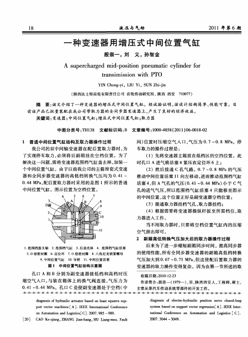
Y N C o gy, I i S N Z ii I h n -i LU Y , U h-n j
( 西 法 士 特 齿 轮有 限责 任 公 司 齿 轮 传 动 研 究 所 。 西 西 安 陕 陕 707 ) 10 7
o u m t nadLgsc[ .0 7 95—99 nA t a o n oiisC]20 .8 o i t 8.
[0 C O K —in , H N i —ag H il m u F ut 2 ] A eq g Z A G J bn . U Lmg o . al a n a -
1 8
一
液压 与 气动
21 0 1年 第 6期
种 变 速 器 用 增 压 式 中 间 位 置 气 缸
殷 崇一 ,刘 义, 孙智金
A u e c a g d mi — o i o n u t y i d r fr s p r h r e d p st n p e mai c l e o i c n
作 者 简 介 : 崇 一 ( 99 ) 男 , 西 西 安 人 , 程 师 , 士 , 殷 17 一 , 陕 工 硕
图 1 中 间位 置气 缸结 构 示 意 图
孔 口 A和 B分 别 为 副变 速 器 接低 档 和 高 档 时压 缩空 气人 口, 与装 在箱 体 上 的换 气 阀连 接 , 压 力 为 气 04 一 .4M a . l 04 P 。孔 口 c是 使副 变速 器处 于 空档 ( 中
中图分类 号 : H 3 文献标 识码 : 文章 编号 :0 04 5 (0 1 0 - 1 -2 T 18 B 10 -8 8 2 1 ) 60 80 0
1 普通 中间位置气 缸结构 及取 力器操作 过程 我公 司的双 中间轴 变 速器 在 配 后置 取 力 器 时 , 为 了实 现停车 取力 , 必须 将 后 副箱 挂 在 空档 位 置 。为 了 解决 这一 问题 , 需将 变速器 范 围档气缸 盖去掉 , 加装一 个 中间位置气 缸 。 由于 以前 我公 司 的主箱滑套 式变速
亚德客气动元件概述1556

亚德客气动元件概述气动执行元件气动控制元件气源处理元件气动辅助元件客制化产品气动执行元件SE、SI、SGC/SG系列属ISO15552标准,SC、SU、执行AIRTAC标准(125以上执行ISO6430标准)气缸基本构造与工作原理1234568910111213141 缓冲密封圈2 磁石3 缓冲头4 气缸本体5 滑动轴承6 防尘密封圈7 前端盖8 前气口9 感应开关10 活塞杆11 活塞密封件12 导向环13 后端盖14 缓冲节流阀3、缓冲结束1、活塞即将进入缓冲区2、缓冲开始6、活塞快速前进4、活塞开始前进5、活塞慢速前进缓冲节流气缸的缓冲气缸的密封:气缸密封性能的好坏,是影响气缸性能的重要因素。
按密封原理,可将密封圈分成压缩密封圈和气压密封圈两大类。
压缩密封是依靠安装时的预压缩力使密封圈产生弹性变形而达到密封作用的;气压密封是靠工作气压使密封圈的唇部变形来达到密封作用的。
无气压力时有气压力时压缩空气活塞密封圈(a)(b)材质中文名称使用温度使用场合TPU聚氨酯-40~80°C普通场合(较硬,耐磨)NBR丁腈橡胶-20~80°C普通场合(较软,耐油)FPM(VITON)氟橡胶-20~150°C耐高温序号名称1鱼眼接头2连接板(无)3Y/i 接头4浮动接头5LB轴向固定架6FA/FB法兰固定板7导向装置(无)8TC固定架系列9CB双耳固定架10CR单耳固定架11CA单耳固定架12磁感应开关气缸的安装附件MI/MIC系列MF/MFC系列MG/MGC系列PB/PBR系列MA/MAC/MAR系列MAL系列迷你圆筒气缸产品特点:气缸体积小,结构紧凑,重量轻,缸径小,反应快,可适用于较高频率的工作环境;除MAL系列缸体采用铝合金作硬质阳极氧化外,其它系列缸体均用高精度不锈钢管,强度高,抗腐蚀;前后盖与缸体连接采用铆合滚包结构(MAL采用螺纹及加厌氧胶连接),连接可靠多种后盖形式使气缸安装更方便产品特点简介型号缸径(mm)行程(mm)主要特点SMC替换MI 8~40600ISO6432,螺纹外径粗且外伸较长,不锈钢缸体和活塞杆C85MF20~40600JIS,螺纹外径粗且外伸较短,不锈钢缸体和S45C活塞杆CM2MG 20~63800JIS,不锈钢缸体和S45C活塞杆(SMC为铝合金缸体)CG1PB 4,6,10,12,16300JIS,螺纹外径粗且外伸较短,不锈钢缸体和活塞杆,4为黄铜PBR为316L缸体,PB4/6只可前盖安装,PBR自带安装孔PB:CJ2/CJ1(4)PBR:CJ2RMA 16~63500企标,不锈钢缸体和S45C活塞杆CM2RA2MAL20~401200企标,螺纹外径粗且外伸较短,铝合金缸体和S45C活塞杆,细螺纹连接MI/MIC系列MF/MFC系列MG/MGC系列PB/PBR系列MA/MAC/MAR系列MAL系列型号缸径(mm)行程(mm)可调行程(mm)主要特点SMC替换ACE 12~10030010~100ISO21287,结构紧凑,螺纹连接C55ACP 12~100400DIN,TPU防撞垫,螺纹连接-ACQ 12~100100JIS,TPU防撞垫,扣环固定CQ2SDA12~100130企标,NBR防撞垫,扣环固定-ACQ 系列SDA 系列ACP 系列薄型气缸ACE系列采用进口润滑脂,降低了低温低速时的爬行现象一旦加油润滑,中途不可停止可选用耐高温密封材料可保证气缸在150℃条件下正常工作缸筒与前端盖采用机械弹力扣环连接,组装拆卸容易,便于维修;后盖与本体均采用铆合式连接,更加可靠活塞上增加了耐磨环结构,使其导向精度和支撑能力大为提高气缸本体作硬质氧化、滚压处理运动阻力小,缸体更耐磨复动3000KM,单动300万次结构特点衍生产品大缸径系列(125,140,160 mm)行程10~300mm,防撞垫和密封O令均为NBR 长行程系列(32~100 mm)行程125~300 mm前盖导向套加长,32无带导杆系列TACQ(12~100 mm)不回转精度高12,16为±0.2°,20~100为±0.1°SDAT复动多位置型SDAW双轴复动多位置型多位置气缸多位置气缸SDAW(四位置)多位置气缸SDAT(三位置)薄型治具气缸MD 系列MK 系列型号缸径(mm)行程(mm)可调行程(mm)主要特点SMC替换MD 6~326010,20,30企业标准,后端盖扣环固定-MK 6~326010,20,30JIS,带导向杆防旋转CU MU6,8,1030-JIS,带导向凸台,定位准确CUJMU 系列多位置自由安装气缸HLH 系列型号缸径(mm)行程(mm)主要特点SMC替换HLH 6,10,16,2060侧滑轨,循环滚珠+直线导轨,高精度,中载荷MXH HLQ 6,8,12,16,20,25150循环滚珠+直线导轨,高精度,中载荷MXQ HLS150交叉滚柱+直线导轨,高精度,重载荷MXSHLS 系列进出气口(3面,默认底部)HLQ 系列定位销孔(滑块+本体)定位销孔(滑块+本体)滑台固定板循环滚珠式导轨组合缸体固定板循环滚珠式导轨组合缸体HLQ单轨(6/8) HLQ双轨(12/16/20/25)HLS(6/8/12/16/20/25)导轨安装结构外部挡块型式安装与使用说明气缸固定治具固定HFY 系列型号缸径(mm)使用频率主要特点SMC替换HFZ 6~40180 c.p.m 线性导轨设计,高精度,高刚性MHZ2HFY 6~32180 c.p.m 角度开闭使用范围广,自带节流阀MHC2HFP 6~32180 c.p.m(60)夹紧力大,夹持精度高-HFR10~3260 c.p.m180°开闭型,防尘设计MHY2HFZ 系列HFP 系列HFR 系列专利结构HFZ HFY安装与使用说明HRQ 系列型号缸径(mm)回转角度(°)重复精度主要特点SMC替换HRQ2,3,7,10,20,30,50,70,100,2000~190°0~200°(>70)调整螺丝:±0.2°油压缓冲器:±0.05°双活塞齿轮齿条式,运转平稳固定防撞垫+油压缓冲器MSQ本体采用铝挤型模具,表面喷细砂后硬阳处理前盖压铸成型,表面喷砂-烤漆处理。
费斯托无杆气缸 DGC-K-18- - 订货号1312500工作原理介绍

费斯托无杆气缸 DGC-K-18- - 订货号1312500工作原理介绍费斯托无杆气缸 DGC-K-18- - 订货号1312500工作原理介绍无杆气缸简介:无杆气缸是指利用活塞直接或间接方式连接外界执行机构,并使其跟随活塞实现往复运动的气缸。
这种气缸的优点是节省安装空间,分为磁偶无杆气缸(磁性气缸)与机械式无杆气缸。
技术参数行程1 mm ... 3000 mm活塞直径18 mm缓冲气动缓冲,两端可调安装位置可选位置检测通过接近开关派生型双端进气口标准活塞加长活塞工作压力0.2 MPa ... 0.8 MPa工作压力2 bar ... 8 bar工作模式双作用CE 认证(见合格声明)符合欧盟防爆指令 (ATEX) CE 标记(见合格声明)根据 UK EX 指令防爆区 1 (ATEX) 区 2 (ATEX) 区 22 (ATEX) ATEX 气体类别II 2GATEX 防尘类别II 3D气体防爆阻燃类型Ex h IIC T4 Gb X防尘防爆阻燃类型Ex h IIIC T120°C Dc X防爆环境温度-10°C <= Ta <= +60°C工作介质压缩空气,符合 ISO 8573-1:2010 [7:-:-]工作和先导介质说明可用润滑介质工作(之后须一直润滑介质工作)耐腐蚀等级 CRC1 - 低耐腐蚀能力油漆湿润缺陷物质(PWIS)符合性VDMA24364-B1/B2-L适合食品行业使用见补充材料说明环境温度-10 °C ... 60 °C缓冲长度16 mm6 bar 时的理论力值,返回行程153 N6 bar 时的理论力值,前进行程153 N备用接口查看产品图纸安装方式带附件材料说明RoHS 合规盖子材料压铸铝密封件材料NBR TPE-U(PU)无杆气缸原理无杆气缸和普通气缸的的工作原理一样,只是外部连接、密封形式不同。
气缸两边都是空心的,活塞杆内的永磁铁带动活塞杆外的另一个磁体(运动部件),它对清洁度要求蛮高的,磁耦无杆气缸经常要拆下来用汽油清洗,这与它的工作环境有关。
海尔55C四气缸汽机说明书
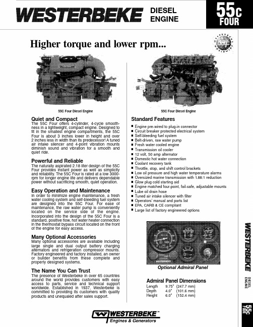
Performance Data Number of cylinders 4 Cylinder vertical in-line Cycles 4 CycleDisplacement 133.0 cu. in. (2.18 liter)Bore and stroke 3.35" x 3.78" (85 mm x 96 mm)Compression ratio 21.5:1Maximum angle of installation Not to exceed 14˚Maximum angle of rotation Not to exceed 30˚ for 30 min.Crankshaft, direction of rotation Counterclockwise as viewed fromflywheel endPropeller shaft, direction of rotation Right hand–std. trans.Dry weight 448 lbs (203.2 kilos)Combustion system Swirl typeAspiration Naturally aspiratedLubrication system Forced lubrication by gear pumpCooling system 7.25 quarts (6.86 liters)Starting aid 12 volt sheathed type glow plugEngine stop ElectricFuel injection pump Bosch typeGovernor Centrifugal typeInjectors Throttle typeFuel filter PrimaryLube oil filter Full flow,spin-on elementLubricant capacity 8quarts (7.6 liters)Lube oil cooler Fresh water cooledFuel transfer pump ElectricalFuel supply and return piping 1/4" ID (6.35 mm) minimum3/8" ID (9.53 mm) maximumStarting motor 12 volt, solenoid actuatedBattery charging alternator 50 ampere (12 volts)Cold cranking amps 284 amps at 77˚ FElectrical system 12 volts DC, negative ground Cylinder head Cast Iron Cylinder block Cast Iron Crankshaft Ductile cast iron, five main bearings Valves Overhead valves Fuel System Self bleeding Intake system Tuned intake silencer with air filter for maximum noise reduction Cooling system Fresh water-cooled with tube and shell type heat exchanger Exhaust manifoldCast aluminum, fresh water-cooled with built -in expansion tankAuthorized Dealer Standard gear ratio1.88:1Mounting centers16.0" & 18.5"Flexible mounts Engine matched adjustablefail safe neoprene type Domestic hot water connection Coolant recovery tank Battery charging alternator 50 amp, 12 volt Starting aid Control brackets Throttle and shift Prewired Engine Belt-driven raw water pump Lube oil drain hose Transmission oil cooler Oil fill Top and service side Circuit breaker protected electrical system Operator’s Manual and Parts List Construction–Engine ComponentsWesterbeke Corp., Myles Standish Industrial Park, 150 John Hancock Road, Taunton, MA 02780-7319, U.S.A. • Telephone: (508) 823-7677 • Fax: (508) 884-9688 • Website: Specifications Subject to Change without Notice.FC-3/09Captain panel with alarm (tachometer with lights)Admiral panel with alarms (tachometer with gauges)Dual station senders Other gear ratios Consult local Distributor Hydraulic transmissions Consult local Distributor Remote expansion tank Provision for refrigeration compressor Muffler and fittings “A” and “B” on board spare parts kits Alternator,72, 90 amp single output; 135, 160, 190 dual output Anti-siphon valve for overboard cooling discharge water Technical Manual Exhaust connection (water injected 70˚ elbow)Propeller shaft couplings (rigid/flexible)–available standard sizesOptional Equipment Dimensions Inches (millimeters)Specification Standard Equipment。
不锈钢气缸使用说明书
文件No.CG1*-OM0006N不锈钢气缸C*G5*N**SR/V-*C*G5*A**SR/V-*安全注意事项 P2 产品个别注意事项 P4 1.产品规格 P61-1.规格2.设置方法・使用方法 P7 2-1.使用空气2-2.设计注意事项2-3.安装・设置2-4.使用环境条件2-5.速度控制2-6.关于缓冲2-7.方向控制2-8.磁性开关3.维修保养 P163-1.点检3-2.密封圈的更换方法3-3.消耗品3-4.故障与对策4.气缸使用的基本回路 P245.构造 P25-1-安全注意事项此处所示的注意事项是为了确保您能安全正确地使用本产品,预先防止对您和他人造成危害和伤害而制定的。
这些注意事项,按照危害和损伤的大小及紧急程度分为「注意」「警告」「危险」三个等级。
无论哪个等级都是与安全相关的重要内容,所以除了遵守国际规格(ISO/IEC)、日本工业规格(JIS)*1) 以及其他安全法规*2)外,这些内容也请务必遵守。*1) ISO 4414: Pneumatic fluid power -- General rules relating to systemsISO 4413: Hydraulic fluid power -- General rules relating to systemsIEC 60204-1: Safety of machinery -- Electrical equipment of machines (Part 1: General requirements)ISO 10218: Manipulating industrial robots-SafetyJIS B 8370: 空气压系统通则JIS B 8361: 油压系统通则JIS B 9960-1: 机械类的安全性‐机械的电气装置(第1部: 一般要求事项)JIS B 8433: 产业用操作机器人-安全性等*2) 劳动安全卫生法 等①本产品的适合性由系统设计者或规格制定者来判断。
导向气缸-FESTO

速度 [m/s] 缸径 ∅ 缓冲 P 最大速度, 伸出 最大速度, 退回
力 [N] 缸径 ∅ 6 bar时,力的理论值, 伸出 6 bar时,力的理论值, 退回
12
16
20
25
32
40
50
63
80
100
0.8
0.8
0.8
0.8
0.8
0.8
0.6
0.6
0.4
0.4
0.8
0.8
0.8
0.8
0.8
0.8
0.6
5
导向气缸 DFM
外围元件一览
2 3
1 4
附件
1 快插接头 QS
2 接近开关 SME-/SMT-8
3 沟槽盖 ABP-5-S
4 单向节流阀 GRLA
– 定位套 ZBH
1 4
简要说明 用于连接标准外径气管 可以集成于缸筒内 保护传感器电缆,防止灰尘进入传感器槽 用于调节速度 供货范围包括4件
页码/Internet quick star 60 61 61 60
12, 16
活塞杆位于一 20, 25
端
32
40, 50, 63, 80, 100
[mm]
10, 20, 25, 30, 40, 50, 80, 100 20, 25, 30, 40, 50, 80, 100 20, 25, 30, 40, 50, 80, 100, 125, 160, 200 25, 50, 80, 100, 125, 160, 200
DFM-B带循环滚珠轴承导轨 DFM-B 活塞杆位于一 端
12, 16 20, 25, 32 40, 50, 63
10, 20, 25, 30, 40, 50, 80, 100, 125, 160, 200 20, 25, 30, 40, 50, 80, 100, 125, 160, 200, 250, 320, 400 25, 50, 80, 100, 125, 160, 200, 250, 320, 400
EMC产品型号对照表
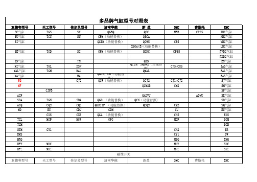
SR550-PN3D(功能替换) XQV5503(功能替换) SR550-EN3D(功能替换) XQV5403(功能替换) SR551-CN4D(功能替换) XQV5304(功能替换) SR551-PN4D(功能替换) XQV5504(功能替换) SR551-EN4D(功能替换) XBKK022-1.6 8W3410-06(功能替换) 8W3410-08(功能替换) 8W3510-10(功能替换) XQV5404(功能替换)
G321EB G321PPL G321PP G321PB S3HS-08-B S3L-08-B S3PL-08-R S3PP-08-G S3PF-08-R S3PM-08-R S3B-08 M3HS-210-08-B M3L-210-08-B M3PL-210-08-R M3PP-210-08-G M3PF-210-08-R M3PM-210-08-R M3B-210-08 M5HS-210-08-B M5L-210-08-B M5PL-210-08-R M5PP-210-08-G M5PF-210-08-R G322TB G322R G322EB G322PPL G322PP G322PB G322 G522TB G522R G522EB G522PPL G522PP
TG3532A-10C TG3542A-15C TG3512A-06E TG3522A-08E TG3532A-10E TG3542A-15E TG3512A-06P TG3522A-08P TG3532A-10P TG3542A-15P
4A330-10C 4A430-15C 4A130-06E 4A230-08E 4A330-10E 4A430-15E 4A130-06P 4A230-08P 4A330-10P 4A430-15P
CTM-中文说明书

Ra≤0.3um ≤0.1﹪ 450MM3/MIN(IP40 铜—钢)
7
DM-CUT CTM 系列三轴数控电火花成型机床
2.2 机床概况
电火花成型机加工是模具制造业及特种零件加工中广泛采用的一种特种加 工方法,它具有高精度、高效率、工作可靠、成本低等优点。
本 机 是 北 京 市 迪 蒙 卡 特 机 床 有 限 公 司 研 制 的 一 种 放 电 加 工 机 床 。它 具 有 操 作 简便、加工精度高、电极损耗小、效率高、高光洁度等特点。
● 机床操作人员必须事先接受本设备的使用培训,学习相关的安全运行知 识。 本机床严禁无人操作,不得离岗。
● 保养作业员须限定为有资格的人员。为保护作业人员及保养人员不受事故 伤害,有关电的维护作业须由电气专业维修人员或其监督下实施。
● 本机床依据如下安全标准实施: GB5226.1-2002 《机械安全 机械电器设备 第 1 部分 通用技术条件》 GB13567-1998 《电火花加工机床 安全防护技术要求》
2.1.2 主要技术指标
输入电源
三相 380V/50HZ
输入功率 控制轴数 最大指令值
6KVA 3 ±9999.999MM
最大电流输入值
加工电压 输入方式 位置指令
40(50A 控制柜) 80(100A 控制柜) 90V / 120V 键盘 绝对/增量
2.1.3 加工指标
最佳粗糙度 ห้องสมุดไป่ตู้小电极损耗 最高效率
到工作液面的最小距离)应与工作电流相适应。 工作电流≤50A 时,液面高度应≥50mm,工作电流每增大 10A,液面高度应 增加 10mm。 ● 在机床边必须配备灭火器等消防器材,灭火器容量为 2kg,用户应严格按 灭火器使用说明书之规定进行维护和保养,经常检查压力,定期更换药 剂,此类工作也可委托就近的专业厂家进行。
