风管施工说明书
直流变频风管机说明书

用户须知
1)使用本机前请仔细认真的阅读本手册,并按手册指导正确操作。 2)特别提醒您注意以下两个标识的意义:
警告!:表示如操作不当,有可能会造成人员伤亡或严重伤害的标志。 注意!:表示如操作不当,有可能会造成人员伤害或财物损坏的标志。
安装使用说明书
直流变频风管送风式空调机组
适用机型: FGR2.6Pd/E(S)Na,FGR2.6Pd/ENa FGR3.5Pd/E(S)Na ,FGR3.5Pd/ENa FGR5Pd/E(S)Na,FGR5Pd/ENa FGR7.2Pd/E(S)Na,FGR7.2Pd/ENa
珠海格力电器股份有限公司
二、线控器操作指南
1、外观介绍
XK1 0
2、线控器液晶图示
图 4 线控器外观
线控器液晶图示说明:
图标
显示名称
扫风
新风
睡眠
自动模式
制冷模式
除湿模式
送风模式
制热模式
图 5 线控器液晶图示 显示内容说明 扫风开关显示。
新风模式(模式 1 ~ 10)。 睡眠开关显示。
自动模式图标显示。 制冷模式图标显示。 除湿模式图标显示。 送风模式图标显示。 制热模式图标显示。
三、遥控器操作指南������������������������������������������������������������� 15 1、遥控器各按键的名称及作用������������������������������������������������� 15 2、运行操作指南—一般步骤(如图 21)���������������������������������������� 17 3、运行操作指南—可选步骤(如图 22)���������������������������������������� 17 4、特殊功能介绍������������������������������������������������������������� 17 5、遥控器电池更换及注意事项������������������������������������������������� 18
施工说明
施工说明一、一般规定1.空调通风工程的施工与验收应按本说明进行,所有设备应按照生产商的要求和说明进行安装,说明中未详之处均应遵照国家标准执行,设备及管道的安装应严格按照下列国家规范进行:《通风与空调工程施工规范》 GB50738-2011《通风与空调工程施工质量验收规范》 GB50243-2002《建筑给水排水及采暖工程施工质量验收规范》 GB 50242-2002《高层民用建筑设计防火规范》 GB 50045-95(2005年版)《建筑设计防火规范》 GB 50016-2006《建筑设计防火规范》 GB 50016-2014《建筑防排烟技术规程》 DGJ08-88-2006 J10035-2006 《机械设备安装工程施工及验收通用规范》 GB 50231-2009《风机、压缩机、泵安装工程施工及验收规范》 GB 50275-2010《制冷设备、空气分离设备安装工程施工及验收规范》 GB 50274-2010《工业金属管道工程施工及验收规范》 GB 50184-2011《工业设备及管道绝热工程施工质量及验收规范》 GB 50185-2010《建筑节能工程施工质量验收规范》 GB 50411-2007《通风管道技术规程》 JGJ141-2004《现场设备、工业管道焊接工程施工规范》 GB50236-2011《工业设备、管道防腐蚀工程施工及质量验收规范》 GB50727-2011《多联机空调系统工程技术规程》 JGJ174-2010/J1001-2010 《设备及管道绝热技术通则》GB/T 4727《设备及管道绝热设计导则》 GB/T 8175《建筑机电工程抗震设计规范》 GB50981-20142. 尺寸单位管道标高以米计,其余尺寸以毫米计。
3. 系统标高所注标高除特别注明以该层建筑楼面为起算标高外,其余均以建筑地坪为±0.000的相对标高。
水管、圆形风管的标高均表示管中心的高度位置;矩形风管的标高均表示该管底面(不包括保温层)的高度位置。
风管机安装篇
风管机安装篇一、安装前准备二、机组检查及吊装三、制冷剂管路安装四、冷凝水管安装五、系统管路真空处理六、电源线、通讯线安装一、安装前准备(一)施工材料准备1、铜管应采用脱磷无缝拉制紫铜管2、铜管和冷凝水管保温材料应采用橡塑发泡管3、冷凝水管应采用UPVC管、PP-R管、PP-C管和热镀锌钢管4、电源线应采用护套双绞铜芯线(RVV)(二)安装工具准备二、机组检查及吊装(一)室内机开箱检查1、室内机拆箱前应核对与发票单型号是否一致,室内机开箱后,检查附件是否齐全,内机外观是否完好无损,电机风叶转动是否顺畅;2、内机出厂时,管路内部都充入了约0.05兆帕的氮气,顶住机组配管接头处的顶针,若有气体排出,则证明机组无问题;若无气体排出,则需要检漏或作更换处理;3、确认内机没问题后,根据实际情况改变挡板位置,决定内机是采用后回风口还是下回风口安装;(二)室外机开箱检查1、室外机开箱后,检查外机外观是否完好无损,附件是否齐全,同时观察机组截止阀是否有油迹;2、室内外机检查完成后,用塑料袋进行封装,避免异物进入;(三)室内机吊装基本步骤:定位——钻孔及固定吊杆——室内机吊装——室内机水平调整——防尘处理1、定位:将定位纸板放在墙顶上做好标记,这样就完成了内机定位;注意:室内机定位时应考虑后续管路安装以及售后维修空间;同时应注意回风口200mm内不能有障碍物,预留检修口等;2、钻孔及固定吊杆:吊杆应根据机组的重量采用不同规格型号;3、室内机吊装:帆布固定完成后要进行风口保护,防止灰尘杂物进入内机;室内机吊装时,应多人配合,避免出现安全事故,同时安装过程中,应注意以下几点:(1)吊装时必须使用四根吊杆,吊杆在机组安装后不得有倾斜现象;(2)室内机必须单独固定,不得与其他设备或管件共用吊架;(3)吊杆固定在楼板时,必须用平垫片加螺母固定,每根吊杆必须要用配件中的两个螺母固定室内机,螺母与吊耳之间要加紧固垫,对于有特殊减震要求的,还必须追加减振垫;(4)室内机安装时必须保证机组距楼顶10mm以上;(5)当吊杆长度超过1.2m时,必须在对角线加两条斜撑以防晃动;4、室内机水平调整:室内机初安装完毕后,必须用水平尺对整机进行水平调整,完成机组水平调整后,调整机组往排水方向倾斜,两端吊耳高度相差6-8mm;5、防尘处理:利用机组自带的包装塑料袋,对机组出回风口和电器盒部分,进行封堵防尘处理,避免机组日后使用异常,室内机吊装完成;(四)室外机安装基本步骤:定位——室外机固定1、定位:外机安装和我们家用分体式空调是一样的;(支架不要安装在空心墙体上,否则容易产生振动噪音)主要考虑一下几个方面:(1)支架的固定和机组的固定都要十分牢靠避免机组脱落;(2)充分的散热空间,出风侧要保证200cm的距离,顶部和左侧要保证50cm的距离,这样才能保证机组充分的换热空间和维修空间;2、室外机固定:室外机固定时应用4个外径12mm的螺栓固定,与基础之间应紧密接触,否则会产生较大的振动和噪音;三、制冷剂管路安装安装步骤:支、吊、托架制作安装——管道清洗——配管和管道加工——穿保温套管——管道连接和固定——管道吹污(一)支、吊、托架制作安装1、支、吊、托架制作安装时应根据固定管道的大小选择相应的规格,过小会导致管路保温挤压而影响保温效果,过大不但会浪费,而且无法有效固定管路,容易引起管路振动;2、支、吊、托架的做法要符合国标T616《暖通空调设计选用手册》;3、制冷剂管道,支、吊、托架之间的最小间距(二)管道清洗(三)配管和管道加工1、制冷剂管道安装时应确保走向正确、分支合理、长度最短,尽量减少焊接头和拐弯;2、管道连接时,应严格按规范操作,有曲折的地方应尽量使用弯管器,遵循横平竖直的原则;3、铜管连接内外机都要进行扩口连接,扩口时预留的A值一定要合理,过大会导致边缘开裂,过小的话会导致连接时泄露,请参考以下数据:(四)穿保温套管穿保温套管时应选用与铜管管径相应的规格,同时不能将保温套管从中间剖开进行保温(五)管道连接和固定制冷剂管道对接喇叭口的时候,要保证铜管在一条直线上,不可以倾斜,然后用手旋紧螺母;打紧铜管时,必须用一个扳手对内机上的螺母进行固定,再用另一个扳手旋紧,旋紧的时候力度一定要适当,力度过大会导致喇叭口爆裂,过小会导致喇叭口泄露;四、冷凝水管安装(一)冷凝水管安装应注意以下几点:1、冷凝水管安装前,应确定其走向和标高,避免与其他管线交叉,以保证坡度顺直,管道吊架的固定卡子高度应当可以调节,并在保温外部固定;2、吊架间距要求3、冷凝水管保温层厚度应保证10mm以上,保温材料接缝处,必须用专用胶粘接,然后缠塑料胶带,胶带宽度不小于5cm,保证牢固,防止结露;3、冷凝水管坡度应在1%以上,主干管坡度不得少于0.3%,且不得出现倒坡;4、冷凝水管的三通管连接时,三通管的二通直管应该在同一坡度上,不允许二通管两端有两个坡度;5、排水管最高点应设通气孔,以保证冷凝水顺利排出;6、排水管与内机排水管用波纹管连接;7、管道连接完成后,应做通水试验和满水试验,一方面检查排水是否畅通,另一方面检查管道系统是否有漏水;注意:铜管和水管的保温连接处,一定要用专业的胶水进行粘合,否则的话会产生凝露,气管和液管的喇叭口以及冷凝水管的软连接处,要用机组配备的专用保温棉进行保温;注意:室外机冷暖机组一定要接配水管,将制热时产生的冷凝水排出;五、系统管路真空处理1、选择的真空泵排气量要达到2L/每秒以上,精确度要打0.02mmHg(毫米汞柱)以上;2、连接好管路后,接上压力表抽真空,当真空泵口无白烟冒出来后连续抽0.5个小时,检查真空泵是否达到-0.1兆帕或以上,如果真空泵达不到,说明可能存在泄漏,应再进行一次漏气检查,如仍无泄漏,应再抽1小时真空;如果两次抽真空都不能保持真空度时,确保无泄漏的条件下,就可以判断是管道内含有水分;这时,应该采取真空破坏的方式将水分排出,具体做法,向管道内充入0.05兆帕氮气,抽这空2小时,保真空1小时,如还达不到真空度-0.1兆帕,则重复此操作,直至把水分排完为止;3、抽完真空后,关闭调节阀的阀门,停止抽真空并保持2小时,确认调节阀的压力没有上升,说明真空合格,管路安装完成;注意:拆除压力表管前先打开小阀门,保持管道处于正压状态;六、电源线、通讯线安装分管机因机型不同,电源接线均不同,具体接线方式请参考说明书;电源线安装注意事项:1、空调机组为Ⅰ类电器,请务必采取可靠接地措施,空调机组内部的黄绿双色线为接地线,切不可移作他用,更不可将其剪断,不能用自攻螺钉固定;2、用户电源必须提供可靠接地端,请不要把接地线接到下列地方:自来水管、煤气管、排污管、专业人士认为不可靠的其他地方;3、电源线和通讯线不能交织在一起,必须分开走线,其间距应大于20cm,否则可能导致机组通讯不正常。
格力超薄风管机使用安装说明书
13
6 设定温度显示
14
7 化霜状态显示
15
8 定时时间显示
16
遥控接收头
模式键
设定温度增加键 设定温度减少键 风速键 睡眠键 定时键 开/关键
3
线控器操作指南
1) 开/关机(图 2) 按下开/关键,本机组将会启动。 再一次按下开/关键,本机组将停止。
2)风扇控制(图 3)(图中所示为有关显示区域,以下同) 每一次按下风扇控制键时,风扇速度按如下顺序变化:
送风、自动模式无睡眠功能。
图5
5)运行模式设置(图 6) 每一次按下本键,操作模式按如下顺序变化:
→制冷→除湿→送风→制热→自动
制冷模式时,制冷显示 将点亮,温度必须设定成比现
自动
在的环境温度低。如果设定成比现在环境温度高,本机将
不会进入制冷方式而将只会有风扇动作。
化霜
除湿模式时,除湿显示 将点亮。内风机在一定温度范
→低速→中速→高速→自动→
除湿模式中:风扇速度会自动设定为低速。
3)温度调节(图 4) 按下温度调节键,
▲:用以使设定温度增加; ▼:用以使设定温度减少。 (按下一次本键时,温度将以 1℃为单位增加或减少。)
各种模式下温度设定范围:
制热 -------- 16℃~30℃ 制冷 -------- 16℃~30℃ 除湿 -------- 16℃~30℃ 送风 -------- 不能进行温度的设定 自动 -------- 不能进行温度的设定
14
机
室内机组水平检验
15
安
冷凝水管的安装与测试
16
装
连接管选配及其保护层的安装
17
指
线控器的安装
模压镁板风管风管施工方案

中储西安东兴分公司家属楼及周边棚户区改造项目1#楼(车库楼)通风工程施工方案审批:审核:编制:模压镁板风管施工方案模压镁板风管是以纤维为增强材料,氯氧镁水泥为胶凝材料,通过机械加工生产风管板材,并将风管板材粘合的通风管道。
该风管具有保温性能好、漏风率低、重量轻、强度高、隔音、防潮防热等特点。
1 特点对模压镁板风管提出相应的施工工艺及要求,针对性较强。
对模压镁板风管的工艺流程和工艺要点进行了详细的说明,对施工的指导作用好。
2 适用范围本工艺适用于工业与民用建筑通风、空调工程中模压镁板风管的施工。
3 工艺原理模压镁板风管由两层高强度无机材料和一层保温材料复合而成,不需二次保温,保温性能好,且风管全部采用胶接结构制作而成,无法兰连接,大大提高了风管的密闭性,降低了风管漏风的能量损耗。
4 施工工艺流程及操作要点风管预制风管切割(1)切割矩形板材时应采用平台式切割机。
板材的切割线应平直;切割面和板面成90°角。
切割后的风管板对角线长度误差应小于3mm。
(2)异径风管板的切割,先在风管板上划出切割线,然后用手提切割机切割,小于或大于90°角的转角板,划线时应计算转角大小,确定角度后切割,以保证拼接质量。
专用胶粘剂(1)风管制作、安装必须使用专用胶粘剂,以保证风管的粘接质量。
(2)使用专用胶胶粘剂粘接前,应清除粘贴处的油渍、水渍、灰尘及杂物等。
(3)专用胶粘剂由粉剂A组和液剂B组二部份组成,在现场按制造厂家说明书配制。
为保证专用胶的均匀性,应采用电动搅拌机搅拌。
(4)专用胶粘剂在不同的环境温度下,具有不同的初凝时间,特别是当环境温度低于0°时,专用胶粘剂固化时间更为缓慢。
专用胶粘剂环境温度变化,其最少初凝时间以及粘结后的风管允许安装的最少时间应符合下表的规定:风管制作直管制作(1)在风管左右侧板的两边采用大小不同的刀片,在切割规格板时,同时切割组合用的梯阶线,用工具刀子将台阶线外的保温层刮去,梯阶位置应保证90°的直角,切割面应平整。
复合风管施工方法和技术措施

复合风管施工方法和技术措施第一节复合风管施工工艺和方法(一)、复合风管板的切割:1、切割线平直,风管板对角线长度误差应小于5mm。
梯阶线深度,25mm厚的保温板18-21mm,18mm厚的非保温板11-14mm。
切割线与板面必须成90°角,为风管黑心角拼接成90°角创造条件。
2、异径风管板材的切割:先在风管板上划出切割线,然后用手提切割机切割如小于或大于90°角的截面切割,其角度要正确,以保证拼接质量。
(二)、风管制作方法:1、专用胶的配制:专用胶由粉剂A组和液剂B组二部份组成。
为了运输方便,液剂是由片剂(粒剂)按说明书在现场配制。
A组与B组混合的重量比为10:6左右,搅拌后的专用胶不宜过稠有流动性为宜。
采用电动搅拌机拌和,不得采用棒、手拌和。
专用胶配制后要及时使用,如发现胶体过稠硬化,不能加液剂再稀释使用。
舌U去左右板余料形成台梯型粘接面B、在左右板台阶处敷上专用胶。
胶要均匀、饱满、不缺浆。
C、先将风管底面板放于组装架上。
再将左右侧板插在底面板边沿,左右侧板与上下板对口纵向粘接方向错位100mm,然后将上面板合入左右侧板间。
先用口型箍定位,再用捆扎带将组合的风管捆扎紧。
捆扎带间距600mm左右,捆扎带与风管四转角接合处应用90°护角保护。
■QIT-风管左右侧板□□冂型定位箍(角钢)捆扎带风管上下板将风管上面板合于左右侧板间,然后用冂型定位箍定位,并用捆扎带紧固D、捆扎好的风管周长小于2000mm时,对角线误差不大于3mm,周长大于200mm以上对角线误差不大于5mm。
必要时,在风管内角处临时支撑定位,保证风管四转角90°。
并清除挤压出来的余胶和填补空隙,风管内外壁无残胶。
E、风管上下板与左右板100mm错位处不得留残胶,否则影响风管与风管连接质量。
3、变径风管制作与直管制作方法相同,其中一面或三面风管板是斜面。
4、三通风管的制作(蝴蝶三通)A、相同截面的三通制作:按图纸尺寸切割风管板,顺风方向设置45°导流角,导流角的长度不得小于支风管宽度的二分之一。
建筑工程施工作业指导书_8册
第四节、风管及部件保温工艺标准1适用范围本工艺标准适用于通风与空调系统风管及部件的保温工程。
2施工准备2.1材料要求:2.1.1所用保温材料应具有出厂合格证,并附有相关管理部门的认证及有关法定检测单位的证明。
2.1.2使用的保温材料应符合空调设计参数要求和消防防火规范要求。
2.1.3常用保温材料一般有两大类:1)纤维状:岩棉板、铝箔岩棉板、超细玻璃棉毡、铝箔玻璃棉板等。
2)多孔状:自熄性聚苯乙烯泡沫塑料、聚氨酯泡沫塑料、矿物棉泡沫保温材料。
2.1.4保温附属材料:玻璃丝布、防火涂料,粘结胶、铁皮、保温钉,应符合设计要求及有关规定。
2.2主要机具:圆盘锯或平板锯、手锯、保温刀、钢板尺、圈尺、毛刷子、打包钳等。
2.3作业条件:2.3.1现埸土建结构已完工,无大量施工用水情况发生。
2.3.2风管、部件安装质量符合质量标准,需防腐部位已作好刷漆工作。
2.3.3保温工程冬季或户外施工应有防冻及防雨措施。
2.3.4风管、部件及空调设备绝热工程施工应在风管系统严密性检验合格后进行。
3操作工艺3.1工艺流程:隐检→领料→粘保温钉,保温材下料→铺覆保温材→内保温和检验,聚苯板类或岩棉类外保温→缠玻璃丝布→刷防火涂料→室外保温层外加铁皮壳→检验。
3.2保温材料下料要准确,切割面要平齐,在裁料时要使水平、垂直面搭接处以短面两头顶在大面上。
3.3粘接保温钉前要将风管壁上的尘土、油污擦拭净,将粘接剂分别涂抹在管壁和保温钉的粘接面上,稍后再将其粘上。
3.4矩形同风管及设备保温钉密度应均布,底面不少于每平方米16个,侧面不少于10个,顶面不少于6个。
首行保温钉距风管或保温材料边沿的距离应小于120mm。
3.5保温材料铺覆应使纵、横缝错开。
小块保温材料应尽量铺在水平面上。
3.6各类保温材料做法:3.6.1内保温。
保温材如采用岩棉类,铺覆后应在法兰处保温材断面上涂抹固定胶,防止纤维被吹起。
岩棉内表面应涂有固化涂层。
3.6.2聚苯板类外保温。
厨房排油烟不锈钢风管施工方案

盘锦水游城商业工程厨房排油烟不锈钢风管施工方案编制:审核:审批:中建安装盘锦水游城项目部2012年4月目录一、编制依据1二、工程概述1三、施工工艺1四、工期安排及保证措施6五、质量管理和保证措施8六、安全、环境管理和保证措施9厨房排油烟不锈钢风管施工方案一、编制依据1、本工程施工图纸;2、我国现行的施工验收规范和操作规程;3、我国现行的安全生产、文明施工、环保及消防等有关规定;4、我公司的管理手册;5、施工验收标准。
表1—1 现场采用的施工验收规范二、工程概述餐饮分布于步行街及水游城地下一层至四层,厨房排油烟系统即为步行街及水游城餐饮区域提供厨房排油烟.排油烟机及油烟净化器由小业主自行安装,我司只负责竖井内及水平甩口至服务店铺内一米的排油烟系统安装及水平不锈钢风管的保温工作。
工作内容包括不锈钢风管5000㎡,不锈钢防火阀40个,不锈钢静压箱10个,风管保温600㎡。
三、施工工艺1、主要设备、材料选用表1)风管材质选用表:2)保温材料材质及规格选用表:2、风管制作风管焊接制作工艺流程如下:2。
1≤1250mm 的风管于2500mm —3所示,法兰翻边尺寸为15mm ,风管长边尺寸>2500mm 时,采用对接焊接外加不锈钢槽钢法兰加固的方式,如图2。
1-4所示。
不锈钢风管的加固支架采用不锈钢角钢作为加固支架。
图2.1-1风管长边尺寸≤1250mm 图2.1-2风管长边尺寸>1250mm图2.1—3 风管横向翻边对接焊示意图 图2.1—4 风管横向对接焊外加加固框示意图不锈钢板不锈钢焊丝图2.1—5风管焊接及加固示意图2.2 钢板裁剪下料拟采用宽度为1250mm的不锈钢卷板进行下料,根据风管规格,将钢板分成两段下料。
如1000×400的风管,周长2800mm,长边尺寸小于1250mm,按图2。
1.1进行下料,即需要下两块尺寸为1400mm×1250mm的板材。
1500×600的风管,周长4200mm,长边尺寸大于1250mm,按图2.1.2进行下料,即需要下两块尺寸为(2100+15)mm×1250mm的板材。
风管施工规范
复合风管技术规范2007——01——16发布 2007——01——16实施前言现根据新型复合风管制作、安装实际要求,本公司特起草制定本企业标准,并报请杭州市技术监督局备案,作为科创新型复合风管制作、安装的技术依据,该工艺及技术已获国家专利,施工单位应该具有专利权人的许可,否则视为侵权。
本标准的技术内容是根据“新型复合风管”专利(专利号ZL200520031917.4)工艺及技术、JC/T646-2006《玻镁风管》行业标准、通风与排烟风管的需要和本公司技术进步而编制,其编定按GB/T1.1—2000《标准化工作导则第1部分:标准的结构和编号规则》和GB/T1.2—2002《标准化工作导测》第2部分:《标准中规范性技术要素内容的确定方法》的要求。
主要技术内容:1、总则;2、新型复合风管制作技术规范;3、新型复合风管安装技术规范;4、新型复合风管质量验收要求。
新型复合风管技术施工规程1、总则:为了规范新型复合通风管制作、安装施工,保证工程质量,节约能源,提高工效,特制定本标准。
本标准适用于新型复合风管的制作、安装。
1.1基本规定1.1.1新型复合风管的施工必须与建设单位进行图纸交底,根据图纸和相关技术文件的规定进行施工,并与土建及其他专业工程互相配合。
1.1.2新型复合风管必须选用系列复合风管板制作,并经质检部门检验合格。
1.1.3 风管制作、安装各环节必须逐一检验合格再进入下道工序,并做好相应的质量记录。
1.1.4 施工场地、人员、设备必须按有关规定执行,确保人员安全与产品质量。
1.2 引用标准1.2.1 GB50243-2002 通风与空调工程施工及验收规范。
1.2.2 JCJ141-2004 通风管道技术标准。
1.2.3 JC/T646-2006 玻镁风管。
2、复合风管的制作技术规范2.1 切割设备的要求:a 平台切割机:切割不同规格的风格板b 手提切割机:切割变径、三通,弯头管件板材。
c 固位装置:用于固定风管90°角和捆扎拼装好的风管。
空调施工方案说明(3篇)

第1篇一、项目背景随着我国经济的快速发展,空调已成为现代生活中不可或缺的设备。
为了提高我国空调行业的整体水平,确保空调安装施工的质量和效率,本方案旨在详细说明空调施工的各个环节,包括施工准备、施工工艺、质量控制、安全措施等,以确保空调系统的正常运行和用户满意度。
二、施工范围1. 空调主机安装与调试;2. 空调管道系统安装;3. 空调电气系统安装;4. 空调风管及风口安装;5. 空调系统试运行与验收。
三、施工准备1. 技术准备(1)熟悉空调系统的设计图纸、设备技术参数、施工规范等相关资料;(2)组织施工人员学习空调安装施工工艺和质量标准;(3)对施工人员进行安全教育和培训。
2. 材料准备(1)空调主机、管道、阀门、风机盘管等设备;(2)电气设备、电缆、接线端子等;(3)保温材料、密封材料、粘合剂等;(4)施工工具、检测仪器等。
3. 施工现场准备(1)清理施工现场,确保施工环境整洁;(2)搭建临时设施,如脚手架、防护栏杆等;(3)配备必要的安全防护用品,如安全帽、手套、防护眼镜等。
四、施工工艺1. 空调主机安装与调试(1)主机安装:按照设计图纸要求,将空调主机放置在指定位置,确保主机水平、垂直度符合要求;(2)连接管道:将主机进出水管、进出气管与管道系统连接,确保接口密封、牢固;(3)电气连接:将主机电气线路与电源连接,确保线路正确、安全;(4)调试:开启主机,检查系统运行是否正常,调节系统参数,确保空调系统运行稳定。
2. 空调管道系统安装(1)管道敷设:按照设计图纸要求,敷设管道,确保管道布局合理、美观;(2)管道连接:将管道与主机、风机盘管等设备连接,确保接口密封、牢固;(3)管道保温:对管道进行保温处理,防止热量损失;(4)管道试压:对管道系统进行试压,确保管道无泄漏。
3. 空调电气系统安装(1)电气设备安装:按照设计图纸要求,安装电气设备,确保设备安装牢固、水平;(2)电缆敷设:按照设计图纸要求,敷设电缆,确保电缆布局合理、美观;(3)接线端子连接:将电缆与设备接线端子连接,确保连接正确、牢固;(4)电气系统试运行:开启电气系统,检查设备运行是否正常,调节系统参数,确保电气系统运行稳定。
暖通空调工程施工组织安排及施工方法和程序说明
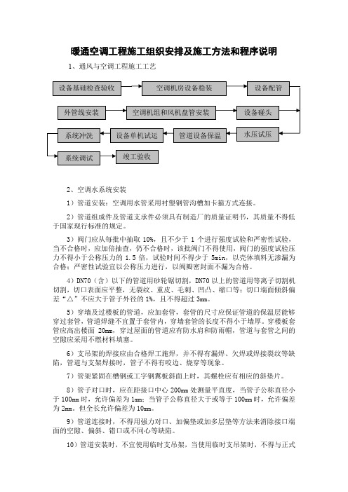
暖通空调工程施工组织安排及施工方法和程序说明1、通风与空调工程施工工艺2、空调水系统安装1)管道安装:空调用水管采用衬塑钢管沟槽加卡箍方式连接。
2)管道组成件及管道支承件必须具有制造厂的质量证明书,其质量不得低于国家现行标准的规定。
3)阀门应从每批中抽取10%,且不少于1个进行强度试验和严密性试验,当不合格时,应加倍抽查,仍不合格时,该批阀门不得使用,阀门的强度试验压力不得小于公称压力的1.5倍,试验时间不得少于5min ,以壳体填料无渗漏为合格;严密性试验宜以公称压力进行,以阀瓣密封面不漏为合格。
4)DN70(含)以下的管道用砂轮锯切割,DN70以上的管道用等离子切割机切割,切口表面应平整,无裂纹、重皮、毛刺、凹凸、缩口等;切口端面倾斜偏差“△”不应大于管子外径的1%,且不得超过3mm 。
5)穿墙及过楼板的管道,应加套管,套管的尺寸应保证管道的保温层能够穿过套管,管道焊缝不宜置于套管内,穿墙套管的长度不得小于墙厚。
穿楼板套管应高出楼面20mm ,穿过屋面的管道应有防水肩和防雨帽,管道与套管之间的空隙应采用不燃材料填塞。
6)支吊架的焊接应由合格焊工施焊,并不得有漏焊、欠焊或焊接裂纹等缺陷,管道与支架焊接时,管子不得有咬边、烧穿等现象。
7)管架紧固在槽钢或工字钢翼板斜面上时,其螺栓应有相应的斜垫片。
8)管子对口时,应在距接口中心200mm 处测量平直度,当管子公称直径小于100mm 时,允许偏差为1mm ;当管子公称直径大于或等于100mm 时,允许偏差为2mm 。
但全长允许偏差为10mm 。
9)管道连接时,不得用强力对口、加偏垫或加多层垫等方法来消除接口端面的空隙、偏斜、错口或不同心等缺陷。
10)管道安装时,不宜使用临时支吊架,当使用临时支吊架时,不得与正式设备基础检查验收空调机房设备稳装 设备配管 水压试压 管道设备保温设备单机试运系统调试 竣工验收 系统冲洗 外管线安装 空调机组和风机盘管安装 设备碰头支吊架冲突,并应有明显标记,在管道安装完后拆除。
风管及风阀、防火阀、散流器等附件技术规格书
通风管道及空气分送附件第一节总则1.1.1 说明本章说明有关通风管道及空气分送附件包括但不限于散流器、调风器、通风口等各种附件的制造和安装所需的各项技术规格要求。
1.1.2 一般要求A. 所有送至工地的通风管道及空气分送附件必须为全新制品,并有不能擦掉的印章标记,以识别不同的材料厚度等级、物料和制造商。
B. 所提供的通风管道及各种空气分送附件须符合招标图纸和本技术规格说明书的规定和建筑师的要求。
C. 所有采用的物料包括通风管道、密封剂、保温材料、粘合物、柔性接合垫圈、粘贴剂、玻璃纤维板等应完全符合当地消防部门的所有规定。
D. 在选取所有散流器及通风格栅口时,除须按各相关的送/回/排风设计要求外,还须同时能满足本技术规格说明书“消声措施”一章中所规定的噪音要求。
1.1.3 质量保证A. 所有散流器、通风格栅、百叶和其它空气分送附件必须是合格产品。
B. 风管须采用非燃材料制造。
而风管道之保温、消声及粘结剂须采用非燃或难燃材料。
C. 须参照和遵从的规范和标准:1. 当地有关部门所制定的规范和守则。
2. 国内验收规范GB 50243-2002 <通风与空调工程施工质量验收规范>。
3. 国家标准GB/T 2518-2004 <连续热镀锌钢板及钢带>。
D. 有关通风管道及相关的空气分送附件所采用的各类材料和施工工艺均须符合本章内所标注的规范/标准,或其它与该标准要求相符的中国或国际认可的规范/标准。
E. 除经特别批准外,所有空气分送系统之附件均须为同一厂家产品。
1.1.4 资料呈审A. 须提交详细显示所有调风阀、分风器、吊架、柔性接头、各类规格和类型风口、检修口和测试口的安装位置之施工图包括但不限于平面图、剖面图、立面图、示意图、清单及详图供审核。
B. 须提交有关调风阀、分风器、吊架、柔性接头、各类风口、检修口和测试口的生产和安装详图供审核。
C. 须提交各类规格和类型的送风格栅和吊顶散流器的认可功能测定数据,包括但不限于如下所述的各项参数:1. 表面风速;2. 静压阻力;3. 在2.5m/s,1.5m/s的送风速度下之送风距离及综合房间风速;4. 按ASHRAE STANDARD 36-72,在混响房间内测试所得的声功率级数据。
格力 2P 天花板内置薄型风管式多联式热泵空调 安装及保养说明书

P00490Q安装及保养说明书室内机本说明书为室内机专用说明书,请阅读本说明书的同时,阅读与之匹配的室外机说明书。
提 示感谢您购买热泵空调。
在使用前,请仔细阅读并理解本说明书。
阅读完毕后,请妥善保存以便日后使用。
多联式热泵空调MULTI-SPLIT AIR-CONDITIONER尊敬的用户:您好!感谢您选择和使用本公司产品。
为了您更好的了解和使用本产品,在使用之前,务必阅读并遵守以下相关事项。
本说明书应被视为空调设备的一部分,请妥善保管。
本说明书对热泵式空调机进行了统一的说明及介绍,因此,既可用于您的空调机也适用于其它空调。
本公司致力于不断地对产品进行改进,如有变更恕不另行通知。
本公司对于空调机因在特定环境中运转而发生的偶然性损坏事故,不负任何责任。
本空调只能作为普通空调使用,不能用于干燥服装、冷冻食品、冷却或加热等其他目的。
请勿将空调安装在以下场合。
否则可能导致火灾、机器变形或者故障。
*有油飞溅的地方(包括机油)。
有易燃气体存在的场所。
*带有硫化气体或硅元素存在的场所(如温泉等)。
*海岸地带多盐性或强酸、强碱的场所,会腐蚀机体。
●●● ●●●●在标明各种危害严重程度时会使用标志性词语(危险、警告和注意)。
关于各种危害等级的定义以及它们对应的标志性词语如下所示:●●本热泵式空调机的设计温度范围如下表所示。
请在此范围内使用。
温 度(℃)不要让机器的出风口直接面对动植物,这样对动植物有不利的影响。
安装和服务工程必须符合当地的标准、法律法规。
空调内机作为“公众不易接近的器具”,要求空调内机的安装高度不应低于2.5米。
本空调安装只能由经销商或专业人员进行,如用户自行安装,可能引起漏水、触电或火灾。
若您有不明之处,请与经销商或本公司指定的服务中心联系。
为了保护环境,请勿将产品随意丢弃,本公司按照国家相关规定可提供回收服务,并按国标要求可提供可更换的部件。
●*23WB 15WB -5DB*15DB 43DB* 27DB 15WB*室内室外室内室外制冷运行制热运行最高最 低*这个温度值可能随不同的室外机而改变。
三菱电机家用中央空调室内机风管机安装说明书

PART NO. 9373385066-02E n g l i s hINSTALLATION MANUALVRF SYSTEM INDOOR UNIT Duct TypeFor authorized service personnel only.Contents1. SAFETY PRECAUTIONS .............................................22. ABOUT THE UNIT2.1. Precautions for using the R410A refrigerant ..........22.2. Special tool for R410A ............................................22.3. Accessories ............................................................22.4. Optional parts .........................................................33. INSTALLATION WORK3.1. Selecting an installation location ............................33.2. Installation dimensions ...........................................43.3. Installing the unit ....................................................44. PIPE INSTALLATION4.1. Selecting the pipe material .....................................74.2. Pipe requirement ....................................................74.3. Flare connection (pipe connection) ........................74.4. Installing heat insulation .........................................85. INSTALLING DRAIN PIPES (8)6. ELECTRICAL WIRING6.1. Electrical requirement ..........................................106.2. Wiring method ......................................................116.3. Unit wiring ............................................................116.4. Connection of wiring .............................................136.5. Air fl ow changing ..................................................137. FIELD SETTING7.1. Setting the address ..............................................147.2. Custom code setting ............................................157.3. Function setting ....................................................168. TEST OPERATION8.1. Test operation using PCB (Outdoor unit) .............178.2. Test operation using Remote Controller ...............179. CHECK LIST ...............................................................1710. ERROR CODES (17)1. SAFETY PRECAUTIONS• Be sure to read this Manual thoroughly before installation.• The warnings and precautions indicated in this Manual contain important information pertaining to your safety. Be sure to observe them.• Hand this Manual, together with the Operating Manual to the customer.Request the customer to keep them on hand for future use, such as for relocating or repairing the unit.WARNING!This mark indicates procedures which, if improperly performed, might lead to the death or serious injury of the user.• Request your dealer or a professional installer to install the unit in accordance with this Manual.An improperly installed unit can cause serious accidents such as water leakage, electric shock, or fi re.If the unit is installed in disregard of the instructions in the Installation Manual, it will void the manufacturer’s warranty.• Do not turn ON the power until all work has been completed.Turning ON the power before the work is completed can cause serious accidents such as electric shock or fi re.• If refrigerant leaks while work is being carried out, ventilate the area.If the refrigerant comes in contact with a flame, it produces a toxic gas.• Installation work must be performed in accordance with national wiring standards by authorized personnel only.CAUTION!This mark indicates procedures which, if improperly performed, might possibly result in personal harm to the user, or damage to property.2. ABOUT THE UNIT2.1. Precautions for using the R410ArefrigerantWARNING• Do not introduce any substance other than the prescribed refrigerant into the refrigeration cycle.If air enters the refrigeration cycle, the pressure in the refrigeration cycle will become abnormally high and cause the piping to rupture.• If there is a refrigerant leakage, make sure that it does not exceed the concentration limit.If a refrigerant leakage exceeds the concentration limit, it can lead to accidents such as oxygen starvation.• Do not touch refrigerant that has leaked from the refrigerant pipe connections or other area. Touching the refrigerant directly can cause frostbite.• If a refrigerant leakage occurs during operation, immediately vacate the premises and thoroughly ventilate the area.If the refrigerant comes in contact with a flame, it produces a toxic gas.2.2. Special tool for R410AWARNING• To install a unit that uses the R410A refrigerant, use dedicated tools and piping materials that have been manufactured specifi cally for R410A use.Because the pressure of the R410A refrigerant is approximately 1.6 times higher than the R22, failure to use dedicated piping material or improper installation can cause rupture or injury.Furthermore, it can cause serious accidents such as water leakage, electric shock, or fi re.Tool name Contents of changeGauge manifold• Pressure is huge and cannot bemeasured with a conventional gauge.To prevent erroneous mixing of otherrefrigerants, the diameter of each porthas been changed.It is recommended to use a gaugemanifold with a high pressure displayrange –0.1 to 5.3 MPa and a lowpressure display range –0.1 to 3.8 MPa. Charging hose• To increase pressure resistance, thehose material and base size werechanged.Vacuum pump• A conventional vacuum pump can beused by installing a vacuum pumpadapter.Gas leakagedetector• Special gas leakage detector for HFCrefrigerant R410A.2.3. AccessoriesWARNING• For installation purposes, be sure to use the parts supplied by the manufacturer or other prescribed parts.The use of non-prescribed parts can cause serious accidents such as the unit to fall, water leakage, electric shock, or fi re.• The following installation parts are furnished. Use them as required.• Keep the Installation Manual in a safe place and do not discard any other accessories until the installation work has been completed.En-2Binder (Medium)Coupler heat insulation (Small)Coupler heat insulation (Large)Special nut A(Large flange)Special nut B(Small flange)HangerHose bandDrain hose insulationEn-4CAUTION• Do not use the unit for special purposes, such as storing food, raising animals, growing plants, or preserving precision devices or art objects.It can degrade the quality of the preserved or stored objects.• Do not install where there is the danger of combustible gas leakage.• Do not install the unit near a source of heat, steam, or fl ammable gas.• Install the unit where drainage does not cause any trouble.• Install the indoor unit, outdoor unit, power supply cable, transmission cable, and remote control cable at least 1 m away from a television or radio receivers. The purpose of this is to prevent TV reception interference or radio noise.(Even if they are installed more than 1 m apart, you could still receive noise under some signal conditions.)• If children under 10 years old may approach the unit, take preventive measures so that they cannot reach the unit.• Decide the mounting position with the customer as follows:(1) Install the indoor unit on a place having a suf fi cient strength so that it withstands against the weight of the indoor unit.(2) The inlet and outlet ports should not be obstructed; the air should be able to blow all over the room.(3) Leave the space required to service the air conditioner.(4) A place from where the air can be distributed evenly throughout the room by the unit.(5) Install the unit where connection to the outdoor unit is easy.(6) Install the unit where the connection pipe can be easily installed.(7) Install the unit where the drain pipe can be easily installed.(8) Install the unit where noise and vibrations are not ampli fi ed.(9) Take servicing, etc., into consideration and leave the spaces. Also install the unit where the fi lter can be removed.(10) Providing as much space as possible between the indoorunit and the ceiling will make work much easier.(11) If installing in a place where its humidity exceeds 80%, useheat insulation to prevent condensation.3.2. Installation dimensions• Provide the space around the unit as shown in the following fi gure.400 mm or more 150 mm or more ❈1❈1 400mm or more when drain from drain pipe.• Provide a service hole for inspection purposes.• Do not place any wiring or illumination in the service space, as they will impede service.• When an air fi lter is installed on the air inlet, provide enough service space to replace the fi lter.AirAirService holeControl box300 mmor more 500 mm or more500 m m o r m o r e100 m mAir AirService spaceControl box300 mm or more1,550 mm or more500 m m o r m o r e100 m mIntake panel3.3. Installing the unitWARNING• Install the air conditioner in a location which can withstand a load do at least fi ve times the weight of the main unit and which will not amplify sound or vibration. If the installation location is not strong enough, the indoor unit may fall and cause injuries.• If the job is done with the panel frame only, there is a risk that the unit will come loose. Please take care.3.3.1. Installing the hangersHanging bolt installation diagram.(Top side)(Right side)270 m mA i rA i rWARNING• When fastening the hangers, make the bolt positionsuniform.740 mm477 mmA i rA i r1,135 m m1,177 m mDuct installation pattern ( CUT PART)Cut Cut Cut Cut(2) Turn up the insulation around the points to be cut ac-cording to the outlet port shape working points so thatthe insulation does not stick out at the(3) Cut with nippers and remove the sheet metal.• The screw holes to install the flange are located behind the round cutouts in the insulation.Duct4.PIPE INSTALLATIONCAUTION• Be more careful that foreign matter (oil, water, etc.) does not enter the piping than with refrigerant R410A models. Also, when storing the piping, securely seal the openings by pinching, taping, etc.• While welding the pipes, be sure to blow dry nitrogen gas through them.4.1. Selecting the pipe materialCAUTION• Do not use existing pipes.• Use pipes that have clean external and internal sides without any contamination which may cause trouble during use, such as sulfur, oxide, dust, cutting waste, oil, or water.• It is necessary to use seamless copper pipes.Material : Phosphor deoxidized seamless copper pipesIt is desirable that the amount of residual oil is less than 40 mg/10 m.• Do not use copper pipes that have a collapsed, deformed, or discolored portion (especially on the interior surface). Otherwise, the expansion valve or capillary tube may become blocked with contaminants.• Improper pipe selection will degrade performance. As an air conditioner using R410A incurs pressure higher than when using conventional refrigerant, it is necessary to choose adequate materials.• Thicknesses of copper pipes used with R410A are as shown in the table.• Never use copper pipes thinner than those indicated in the table even if they are available on the market. Thicknesses of Annealed Copper Pipes (R410A)Pipe outside diameter [mm (in.)]Thickness [mm]6.35 (1/4)0.809.52 (3/8)0.8012.70 (1/2)0.8015.88 (5/8) 1.0019.05 (3/4) 1.204.2. Pipe requirementCAUTION• Refer to the Installation Manual of the outdoor unit for description of the length of connecting pipe or for difference of its elevation.• Use pipe with water-resistant heat insulation.CAUTION• Install heat insulation around both the gas and liquid pipes.Failure to do so may cause water leaks.Use heat insulation with heat resistance above 120 °C.(Reverse cycle model only)In addition, if the humidity level at the installation location of the refrigerant piping is expected to exceed 70 %, install heat insulation around the refrigerant piping. If the expected humidity level is 70-80 %, use heat insulation that is 15 mm or thicker and if the expected humidity exceeds 80 %, use heat insulation that is 20 mm or thicker. If heat insulation is used that is not as thick as specified, condensation may form on the surface of the insulation. In addition, use heat insulation with heat conductivity of 0.045 W/(m·K) or less (at20 °C).4.3. Flare connection (pipe connection)WARNING• Tighten the flare nuts with a torque wrench using the specified tightening method. Otherwise, the flare nuts could break after a prolonged period, causing refrigerant to leak and generate a hazardous gas if the refrigerant comes into contact with a fl ame.4.3.1. Flaring• Use special pipe cutter and fl are tool exclusive for R410A. (1) Cut the connection pipe to the necessary length with apipe cutter.(2) Hold the pipe downward so that cuttings will not enter thepipe and remove any burrs.(3) Insert the fl are nut (always use the fl are nut attached tothe indoor and outdoor units respectively) onto the pipeand perform the flare processing with a flare tool. Usethe special R410A flare tool, or the conventional flaretool. Leakage of refrigerant may result if other fl are nutsare used.(4) Protect the pipes by pinching them or with tape toprevent dust, dirt, or water from entering the pipes.BDieAPipeCheck if [L] is flared uniformlyand is not cracked or scratched.LEn-7Width across4.3.2. Bending pipesIf pipes are shaped by hand, be careful not to collapsethem.Do not bend the pipes in an angle more than 90°.When pipes are repeatedly bend or stretched, the material will harden, making it dif more.Do not bend or stretch the pipes more than three times.Connection pipeTorque wrenchIndoor unit pipe Flare nutHolding wrenchTighten with two wrenches.(Accessories)Binder (Large)(Accessories)Heat insulationheat insulation.CAUTION• After checking for gas leaks (refer to the Installation Manual of the outdoor unit), perform this section.• Install heat insulation around both the large (gas) and small (liquid) pipes. Failure to do so may cause water leaks.INSTALLING DRAIN PIPESUse general hard polyvinyl chloride pipe and connect it withadhesive (polyvinyl chloride) so that there is no leakage.Always heat insulate the indoor side of the drain e a drain hose that matches the size of the drain pipe.Do not perform a rise, trap and air bleeding.Provide a downward gradient (1/100 or more).Provide supporters when long pipes are installed.Use an insulation material as needed, to prevent the pipes from freezing.Install the pipes in a way that allows for the removal of the control box.Drain port Drain cap(Accessories)• Cover the drain cap with the drain hose insulation.Drain hose insulation (Accessories)Unit Unit Drain hose insulation (Accessories)Drain cap0 mmINSTALL THE DRAIN HOSEWorking procedure1) Install the attached drain hose to the drain port of the body.Install the hose band from the top of the hose within the graphic display area. Secure fi rmly with the hose brnd.2) Use vinyl adhesive agent to glue the drain piping (PVC pipe VP25) which is prepared on site or socket. (Apply color ad-hesive agent evenly until the gauge line and seal)3) Check the drainage.4) Install the heat insulation.5) Use the attached heat insulation to insulate the drain port and band parts of the body.DrainhoseArrange the drain hoselower than this portionTrapNO GOODOKRiseNO GOOD1.5 to2.0 mAir bleedingNO GOODCAUTION• Always check that the drain cap is installed to the unused drain port and is fastened with the binder.If the drain cap is not installed, or is not suffi ciently fastened by the binder, water may drip during the cooling operation.6.ELECTRICAL WIRING6. E L E C T R I C A L WWARNING• Electrical work must be performed in accordance with this Manual by a person certified under the national or regional regulations. Be sure to use a dedicated circuit for the unit.An insufficient power supply circuit or improperly performed electrical work can cause serious accidents such as electric shock or fi re.• Before starting work, check that power is not being supplied to the indoor unit and outdoor unit.• For wiring, use the prescribed type of wires, connect themEn-116.2. Wiring method(EXAMPLE)PR SUPPLY OUTDOOR UNIT TRANSMISSIONTRANSMISSION TRANSMISSION POWER SUPPLYPOWER SUPPLY POWER SUPPLYPOWER SUPPLYPOWER SUPPLYREMOTE CONTROL UNIT (MASTER)REMOTE CONTROL UNIT (SLAVE)REMOTE CONTROL UNITREMOTE CONTROLINDOOR UNITINDOOR UNIT INDOOR UNITBREAKERBREAKER POWER SUPPLY REMOTE CONTROLPOWER SUPPLY REMOTE CONTROLBREAKER BREAKERTRANSMISSION 6.3. Unit wiring• Before attaching the cable to terminal block.6.3.1. Power supply cablePower supply cable25 mm Earth cable30m m A. For solid core wiring(1) To connect the electrical terminal, follow the below diagram and connect after looping it around the end of the cable. (2) Use the speci fi ed cables, connect them securely, and fasten them so that there is no stress placed on the terminals.(3) Use an appropriate screwdriver to tighten the terminal screws. Do not use a screwdriver that is too small, otherwise, the screw heads may be damaged and prevent the screws from being properly tightened.(4) Do not tighten the terminal screws too much, otherwise, the screws may break.(5) See the table for the terminal screw tightening torques.(6) Please do not fi x two power supply cables with one screw.St ri p 25 mmLoop Screw with spe-cial washerScrew with special washer Cable end(Loop)Cable end (Loop)CableCableTerminal blockWARNING• When using solid core cables, do not use the ring terminal. If you use the solid core cables with the ring terminal, the ring terminal's pressure bonding may malfunction and cause the cables to abnormally heat up.B. For strand wiring(1) Use ring terminals with insulating sleeves as shown in the fi gure below to connect to the terminal block.(2) Securely clamp the ring terminals to the cables using an appropriate tool so that the cables do not come loose.(3) Use the speci fi ed cables, connect them securely, and fasten them so that there is no stress placed on the terminals.(4) Use an appropriate screwdriver to tighten the terminal screws. Do not use a screwdriver that is too small, otherwise, the screw heads may be damaged and prevent the screws from being properly tightened.(5) Do not tighten the terminal screws too much, otherwise, the screws may break.(6) See the table for the terminal screw tightening torques.(7) Please do not fi x two power supply cables with one screw.St r i p10 mmSleeveScrew with special washerScrew with special washerRing terminalCableCableTerminal blockRing terminalRing terminalWARNING• Use ring terminals and tighten the terminal screws to thespeci fi ed torques, otherwise, abnormal overheating may be produced and possibly cause heavy damage inside the unit.Tightening torqueM4 screw(Power supply /L, N, GND) 1.2 to 1.8 N·m (12 to 18 kgf·cm)En-126.3.2. Transmission and Remote control cableTransmission cableShielded cable (No fi lm)20 mm 45m mRemote control cable20 m m• Connect remote control and transmission cables as shown in Fig. A.Fig. AScrew Terminal blockCableCable of the same caliber: OKCable of the different caliber: NO GOODWARNING• Tighten the terminal screws to the specified torques, otherwise, abnormal overheating may be produced and possibly cause heavy damage inside the unit.Tightening torqueM3.5 screw(Transmission /X1, X2)(Remote control /Y1, Y2, Y3)0.8 to 1.0 N·m (8 to 10 kgf·cm)CAUTION• To peel the fi lm from the lead cable, use a dedicated tool that will not damage the conductor cable.• When installing a screw on the terminal block, do not cut the cable by overtightening the screw. On the other hand, an undertightened screw can cause faulty contact, which will lead to a communication failure.En-136.4. Connection of wiring(1) Remove the control box cover and install each connection cable.ScrewControl box cover(2) After wiring is complete, secure the remote control cable, connection cable, and power cable with the cable clamps.Power supply cable (Field supply)Binder (Medium) (Accessories)Binder (Medium) (Accessories)Remote control cable Transmission cable (Field supply)Binder (Medium) (Accessories)L, N:Power supply cableX1, X2:Transmission cableRemote control cable Y1:Red Y2:White Y3:Black6.5. Air fl ow changingWhen using the ARXB24/30/36/45L model with external Static Pressure under 40 Pa, the Wire (FAN MOTOR) must be replaced as explained below.Replacement method (1) Remove the cover.(2) Remove the Wire (TYPE A) connector from Wire (FAN MOTOR).(3) Remove the Wire (TYPE A) connector from CN4 of the PCB.(4) Insert the Wire (TYPE B) connector into CN4 of the PCB.(5) Insert the Wire (TYPE B) connector into Wire (FAN MOTOR).(6) Insert the cover.En-147.1. Setting the addressCAUTION• Use an insulated screwdriver to set the dip switches.Rotary switch Example: “0”Dip switch “SET 3”Rotary switch Example: “0”SW 1SW 2SW 3SW 4SettingSetting rangeType of switchIndoor unit address0–63Setting example2IU AD X 10 IU AD X 1Refrigerant circuit address0–99Setting example 63REF AD X 10 REF AD X 1(1) Indoor unit addressRotary switch (IU AD x 1)...Factory setting “0” Rotary switch (IU AD x 10)...Factory setting “0”When connecting multiple indoor units to one refrigerant system, set the address at IU AD SW as shown in the T able A.(2) Refrigerant circuit addressRotary switch (REF AD x 1)...Factory setting “0” Rotary switch (REF AD x 10)...Factory setting “0”In the case of multiple refrigerant systems, set REF AD SW as shown in the Table A for each refrigerant system.Set to the same refrigerant circuit address as the outdoor unit.• If working in an environment where the wireless remote controller can be used, the addresses can also be set using the remote controller.• If setting the addresses using the wireless remotecontroller, set the indoor unit address and refrigerant circuit address to “00”.(For information on setting using the wireless remote controller.)CoverWire (Fan motor)External Static Pressure and Required Connector TypeType ABExternal Static Pressure40 – 80 Pa0 – 40 PaWire123456123451 BLACK2 WHITE3 PINK4 PURPLE5 BLUEARXB24 ARXB30 ARXB361 BLACK 2 WHITE 3 RED 4 BLUE 5 PINK 6 PURPLEARXB451 BLACK2 WHITE3 RED4 PINK5 PURPLE6 BLUERemarkFactory setting (Standard static pressure)Accessories (Low static pres-sure)7. FIELD SETTING• Refer to the following three items for setting the FIELD SETTING address. The respective settings are included below.(1) IU AD, REF AD SW settings ............ T his section (2) Remote control settings ................... R efer to the wired orwireless remote control manual for detailed set-ting information. (Set IU AD, REF AD SW to 0)(3) Automatic address settings .............. R efer to the indoor unitmanual for detailed set-ting information. (Set IU AD, REF AD SW to 0)CAUTION• Be sure to turn OFF the power before performing the fi eld setting.Table AAddressRotarySwitch SettingAddressRotarySwitch SettingRefrigerant circuit REF AD SWIndoor unitIU AD SW x 10x 1x 10x 1000000 101101 202202 303303 404404 505505 606606 707707 808808 909909 10101010 11111111 12121212.. ................99996363 Do not set the indoor unit address (IU AD SW) at 64 to 99. It may result failure.RC AD SWRC AD SW1RC AD SW2RC AD SW3Indoor unitRemotecontrollerIndoor unit Indoor unit Indoor unitA B C DA B C D IndoorunitRemotecontrollerConfusionCode change(3) Remote controller addressRotary switch (RC AD SW)...Factory setting “0”When connecting multiple indoor units to one standard wired remote controller, set the address at RC AD SW in sequence from 0.SettingSettingrangeType of switchRemotecontrolleraddress0–15SettingexampleRC ADExample If 4 indoor units are connected.RC AD SW01234567 Address01234567RC AD SW89A B C D E F Address891011121314157.2. Custom code settingSelecting the custom code prevents the indoor unit mix-up.(Up to 4 codes can be set.)Perform the setting for both the indoor unit and the remote controller.En-15En-16Function detailsFunctionFunction numberSetting number DefaultDetailsFilter indicator interval1100Default ○Adjust the fi lter cleaning interval noti fi cation. If the noti fi cation is too early, change to setting 01. If the noti fi cation is too late, change to setting 02.01Longer 02Shorter Filter indicator action1300Enable ○Enable or disable the fi lter indicator. Setting 02 is for use with a central remote control.01Disable 02Display only on central remote control Horizontal swing air fl ow direction2400Default ○Adjust the horizontal swing air fl ow direction.(For horizontal swing equipped models)01Left half 02Right half Cool air temperature trigger3000Default ○Adjust the cool air trigger temperature. To lower the trigger temperature, use setting 01. To raise the trigger temperature, use setting 02.01Adjust (1)02Adjust (2)Hot air temperature trigger3100Default ○Adjust the hot air trigger temperature. To lower the trigger temperature by 6 degrees C, use setting 01. To lower the trigger temperature by 4 degrees C, use setting 02. To raise the trigger temperature, use setting 03.01Adjust (1)02Adjust (2)03Adjust (3)Auto restart4000Enable Enable or disable auto-matic system restart after a power outage.01Disable○External control4600Start/Stop○Allow an external control-ler to start or stop the system, or to perform an emergency shutdown.* I f an emergency shut-down is performed from an external controller, all refrigerant systems will be disabled.01Emergen-cy stopError report target4700All ○Change the target for reporting errors. Errors can either be reported in all locations, or only on the wired remote.01Display only on central remote control• Custom code setting for indoor unitSet the DIP SW SET 3 SW1, SW2, referring to the Table B.Dip switch “SET 3”SW 1SW 2SW 3SW 4OFFON Table BCustom codeA (Factory setting)BC D DIP SWSET 3 SW1OFF ON OFF ON DIP SW SET 3 SW2OFFOFFONON7.3. Function setting• FUNCTION SETTING can be performed with the wired or wireless remote control.(The remote control is optional equipment)• Refer to the wired or wireless remote control manual for detailed setting information. (Set IU AD, REF AD SW to 0)• Refer to “7.1. Setting the address” for indoor unit ad-dress and refrigerant circuit address settings.• T urn the power of the indoor unit ON before starting the setting.* Turning on the power indoor units initializes EEV , so make sure the piping air tight test and vacuuming have been conducted before turning on the power.* Also check again to make sure no wiring mis-takes were made before turning on the power.。
电气风管加热器规格和安装说明说明书

READ AND SAVE THESE INSTALLATION INSTRUCTIONSflow switch (PDN or PDA) or electronic air flow switch sensors (EAS) and automatic thermal cut-out. This may damage heating elements and controls.Important , direction of installation (refer to arrow on name plate) must be respected. Failure to do so will impair proper operation of thermal cut-out and/or cause overheating of solid state relay(s).Caution, Risk of malfunction , Do not proceed with modification or alteration to internal electric connection or component of the electric heater. Any non-authorized modification will void the warranty.!Features:∙ Zero clearance construction ∙ Horizontal or Vertical air flow∙ Standard control panel door with removable hinges ∙ Approved to CSA and UL standards1 Dimensions2 Installation Tips2.1 Air flow condition to avoid:2.2 Minimum clearance to access control panelCaution , Risk of electric shock and burns. A minimum distance of 39’’ (1m) must be maintained between heating section and any opening or access door in the duct. This applies to all types of heaters. If such distance cannot be maintained, a protective guard (C22.2 No.155 section 4.1.8) must be installed to protect personnel from contact to heating elements and bare live parts.3 HandlingWarning, Risk of failure or malfunction . Do not operate electric heater if heating elements have been damaged during transport or handling.✓ Protective packaging must be kept until installation.✓Electric heater must be handled with care, particularly for the Open Coil electric heater.4 Mechanical installationCaution, Risk of damage and malfunction, Do not block air flow to heating elements, insufficient airflow may damage heating elements and controls.Important , direction of installation (refer to arrow on name plate) must be respected. Failure to do so will impair proper operation of thermal cut-out and/or cause overheating of solid state relay(s),!!!5 Electrical InstallationDANGER: Risk of electric shock. Disconnect all supplies before working on any circuit.CAUTION: Risk of malfunction. Use only copper wires suitable for 221˚F (105˚C).CAUTION: Electric installation must be done by a qualified electrician and must conform to local electrical codes.CAUTION: If a disconnect switch and/or fuses have not been supplied on the control panel of the electric heater, disconnect switch and/or fuses must be installed on supply.CAUTION: Gauge of electric supply wires must be of appropriate section, function of line current, as per local electrical codes.5.1 Power supply wiringSee the name plate for information on voltage and current.✓Connect all wires to appropriate terminals as per the electrical diagram affixed inside the control panel door.✓Correct connection tightening must be verified before start up, and after a short period of operation (typically after 2 weeks).5.2 Typical electric diagram & legendThermal cut-outautomatic reset or Air flow switchor EAS**Single phase power supplyterminalsThermal cut-out Manual reset Disconnect switch3 phases power supplyterminalsNormally opencontactFuseGround terminal Normally closedcontactHeating element InterlockContactor coil TransformerControl circuit supply Back-up safetycontactor coilPneumatic electricswitch (ON/OFF)CommonPilot lightPneumatic electriccontroller(modulating)Solid State Relay inputterminalSolid State Relay outputterminal**Note: Electronic air flow sensor (EAS) is available/installed for heaters less than 50A and dimensions less than 48”x40”. Some restriction may apply.I5.3 Control signal selection and connection5.3.1 Electric ON/OFF signalConnect the contact demand wires to terminals com & 1, 2, 3, etc…of the electric heater.Information about mechanical Air flow switch (PDN or PDA)Upon application of 0.05’’w.c. (12Pa) minimum pressure, mechanical airflow switch will activate internal normally open and normally closed contact.Install pitot tube into the air duct up flow of electric heater. Make sure that the arrow is in the direction of air flow.5.3.2 Pneumatic ON/OFF signalConnect a ØInformation about Pneumatic electric switch (PSO or PSC)Upon application of demand pressure, pneumatic switchwill activate internal normally open (PSO) or normally closed (PSC) contact.Set point is adjustable from 2 to 20PSI (14 to 138kPa)5.3.3 Electrical modulating signal, 0-10 or 2-10Vdc or 4-20mAInformation about Neptronic ®electronic controller (HEC)Neptronic® electronic controller (HEC) is a universal controller accepting any input signal used in the HVAC industry and converting it to a modulating and/or ON/OFF control signal to solid state relay(s) and contactor(s).If the electric heater is equipped with only one modulating stage, part number is HEC0000; and if the electric heater is equippedPneumatic signal inlet port5.3.4 Electric digital signal, AC or DCInformation about Neptronic ®electronic controller (HEC)If the electric heater is equipped with only one modulating stage, part number is HEC0000; and if the electric heater is equipped5.3.5 Electric Neptronic ® signal, resistiveConnect the control signal demand wires to terminals A17 & A18 of the electric heater.Internal set point option:Temperature set point is adjustable directly on the electric heater, preventing over adjustment by user. If the electric heater is equipped with only one modulating stage, part number of electronic controller is HEC0000; and if the5.3.6 Pneumatic modulating signal, 0-15 PSIConnect the tube of the pneumatic signal to the port high pressure and leave the other port free.Information about pneumatic electric controller (PCD or PCR)Upon a pneumatic signal from 0-15 PSI (0 to 103kPa); and a minimum differential of 4 PSI (27kPa), pneumatic electric controller will send a 0 to 10Vdc electric signal to HEC. Direct (PCD) or reverse (PCR) acting preset at factory.Part number of the Neptronic® electronic controller when used with pneumatic electric controller is HEC1000.Pressure input (+)6 Operation conditionAir Flow :Air flow must not be lower than the minimum air flow indicated on name plate.Air flow going through the electric heater must be free of combustible particle, flammable vapour or gas.Open Coil: Air flow going through the electric heater must be free of dust.Zero clearance construction:Neptronic electric heaters are designed and approved for zero clearance to combustible material. Insulation material may be installed directly onto electric heater surfaces or onto air duct. However control panel must be accessible for maintenance.Warning, Risk of fire and/or malfunction, Do not install insulation directly on heating elements.7 MaintenanceNeptronic® electric heater does not require specific maintenance; however, we recommend a yearly inspection, typically before winter season or after a long term shut down.1)Visual inspectionRisk of electric shock. Disconnect all supplies before any visual inspection.✓Verify good condition of heating element.Heating element must be clean, free of dust or lint.✓Open Coil: Verify carefully that there is no dust accumulation. Any dust of lint accumulation can lead to fire hazard.✓Verify any indication of overheating condition (discoloration) as well as any trace of oxidation (rust).2)Electrical inspectionRisk of electric shock. Disconnect all supplies before any electrical inspection.✓Verify correct electrical connection tightening.✓Verify the good condition of fuses (if any).✓Verify resistance of each circuit against ground.✓Verify correct operation of contactor(s).If necessary, electrical component must be replaced only with identical original component.8 Quick Troubleshooting GuideRisk of electric shock. Disconnect all supplies before any electrical inspection and troubleshooting.Any service and troubleshooting must be done by a qualified electrician.Symptom: Electric heater does not react to heating demand.Troubleshooting stepsStep 3Control signal selection jumpersStep 6TPM GreenLEDOutput terminals to heatingstages contactorsStep 7Output terminals to SSR(s)Step 5Input terminals from electronic airflowsensors9 Technical SupportFor any questions or specific requests, please consult our website: Or call: 1 800 361-2308, and ask for the Electric Heater Department.or (514) 333-1433Fax : (514) 333-3163。
空调施工说明
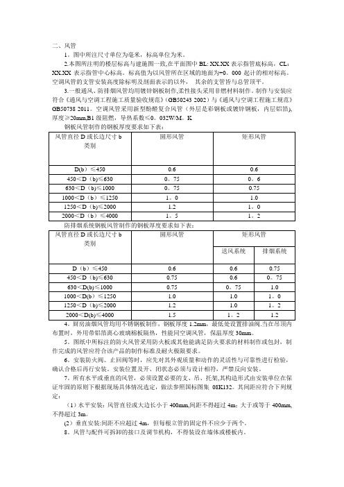
二、风管1。
图中所注尺寸单位为毫米,标高单位为米。
2.本图所注明的楼层标高与建施图一致,在平面图中BL: XX.XX表示指管底标高,CL:XX.XX表示指管中心标高。
标高值为以风管所在区域的地面为+0。
000起计的相对标高。
空调风管的支管安装高度除标明及剖面表示的以外,其余的支管皆与总管顶平。
3.一般通风、防排烟风管均用镀锌钢板制作,柔性接头采用非燃材料制作。
制作与安装应符合《通风与空调工程施工质量验收规范》(GB50243-2002)与《通风与空调工程施工规范》GB50738-2011。
空调风管采用新型酚醛复合风管(外层是彩钢板或镀锌钢板,内层铝箔),厚度≥20mm,B1级阻燃,导热系数≤0。
032W/M。
K4。
厨房油烟风管均用不锈钢板制作,钢板厚度1.2mm,最低处设置排油阀.当在吊顶内布置时,外用带铝箔离心玻璃棉板隔热,性能同空调风管,保温厚度30mm。
5。
图纸中所标注的防火风管采用防火板或其他能满足防火要求的材料制作或包封,制作完成的风管应符合该产品的制作标准及耐火极限要求。
6。
安装防火阀、止回阀等时,应先对其外观质量和动作的灵活性与可靠性进行检验,确认合格后再行安装。
安装位置及开、闭状态必须与设计相符,严禁反向安装。
7。
所有水平或垂直的风管,必须设置必要的支、吊、托架,其构造形式由安装单位在保证牢固的原则下根据现场具体情况选定,做法参照国标图集08K132。
其间距应符合下列规定:(1)水平安装:风管直径或大边长小于400mm,间距不得超过4m;大于或等于400mm,不得超过3m。
(2)垂直安装:间距不应超过4m,但每根立管的固定件不应少于两个。
8。
风管与配件可拆卸的接口及调节机构,不得装设在墙体或楼板内。
9.当设计图中未标出测量孔位置时,安装单位应根据调试要求在适当的部位配置测量孔。
10.安装调节阀等配件时,必须注意将操作手柄设置在便于操作的部位。
11.防火阀等处必须有单独的支、吊架和防止风管变形而影响关闭的措施.12。
- 1、下载文档前请自行甄别文档内容的完整性,平台不提供额外的编辑、内容补充、找答案等附加服务。
- 2、"仅部分预览"的文档,不可在线预览部分如存在完整性等问题,可反馈申请退款(可完整预览的文档不适用该条件!)。
- 3、如文档侵犯您的权益,请联系客服反馈,我们会尽快为您处理(人工客服工作时间:9:00-18:30)。
风管施工说明书
7.4风管施工要求
7.4.1所有风管应按设计图及详图所示尺寸制作,其外表须平整且不得漏气。
但为配
合现场,如交会冲突等必须更改时,承包人应绘详图并说明原因,请业主核定
后,始可施工。
除另有规定外,风管大小尺寸改变之处应小于15 度,
风管圆弯头中心线半径至少应为风管宽度之一倍,风管直角转弯处内部应设置
导风片,导风片迎风端应予卷边,上下端则应钉牢于风管上。
7.4.2风管分岐处均应装置分岐式开关或引风片以便调整及锁定,该开关之材料为镀锌
铁皮,迎风一端应予折边加强,以防震动。
7.4.3风管分支管上须附可调整风量之调节器,以利系统平衡用。
7.4.4风管所须之铆钉、螺栓等铁件均须经镀锌处理。
7.4.5角铁、吊杆等铁件应采用热浸镀锌处理。
7.4.6每只设备排风管均须预留一个风量测试孔。
7.4.7风管安装
(1) 所有风管,除另有规定外,均应安装紧贴梁下
(2) 主风管皆须固定吊装至最高点,若有与其它工程冲突到须协调再施工,若须更改
风管必须配合修改。
(3) 工程中需用到软质风管,须特别加强其两端之束缚,且若软管不够长需更换不得
有相接情形,以免脱落或断裂的现像。
(4) 过滤网集风箱接软质风管处,除了加强束缚外并在集风箱和风管接触面涂上硅
利康胶以防止脱管现象,若运转六个月内发现脱管现象,厂商应全部检查并改善。
(5) 软管勿有360°回转拉向出风口之现象。
且2M 以上软管皆须于中间部分以管束
加以悬吊,使其勿压于天花板上。
(6) 从主风管挖洞加装之出风口〔欲接软管者〕其与主风管相接之隙缝常过大而漏失
冷气甚多,另主风管各段相接处〔法兰〕亦常是冷气逸出之部位,要能完全杜绝此类的冷气漏失。
(7) 风管必须安装牢固,挠性风管应采最短距离
(8) 风管转弯处,其截面积不得减少或凹陷
(9) 风管的保温棉须与风管结合良好,勿有脱落现象,且保温棉衔接处不得有隙
缝。
法兰处之保温处亦需特别注意之。
(10) 从室外入室内之风管,须做止水环处理,勿让其将室外之水流带入室内。
(11) 风管弯头中心线其半径应保持二倍宽度,弯头内应装置导风片,其迎风一端应
于卷边,上下两边应铆牢于风管上。
(12) 凡风管贯穿有防火等级的墙壁、地板时,都必须安装防火风门。
(13) 风管制作期间,风管内部应以酒精调水擦拭干净,并以透明塑料布封住开口
处,以防灰尘进入。
(14) 挠性软管弯曲时,其弯曲半径不得小于直径。
(15) 挠性软管须与高温设备及高温风管保持30cm 距离。
(16) 风管厚度单位为寸:
风管宽度30 ”以下时为24#
风管宽度31” ~54”时为22#。
风管宽度55” ~84”时为20#。
风管宽度84”以上时为18# 。
风管固定角铁之规格为:
风管宽度54”以下用 1 1/2 ”*1 1/2 ”
风管宽度55”以上用2”*2 ”。
(17) 穿越防火墙,于穿墙前后2M 范围内之保温材料应采用耐燃材质施工。
(18) 所有风口安装前,须将样品、样式及颜色送请业主核定,经认可后始可安装。
(19) 风管系统完成后,各出风口应作风量、风速试验,并制成纪录 3 份附于竣
工资料中。
每一出风口不应有显着之乱流及杂音产生,如装置或制作不良,应立
即拆除重做,并再做试验至合格为止。
7.5风管附件
风管分岐处,应装分岐分风片,于调整风量后标示再固定之。
7.5.2手控风门(V.D.):
7.5.1 分风片(Splitter Damper):
风管厚度15cm以下者采用单叶片式调整器,16cm以上者采用多叶片式, 八字形对开之型式,叶片及框架需加以适当之补强,坚固而不得变形。
圆形风管则应采用蝶形风门(气密型)。
7.5.3百叶风门:
回风口或采风口(RG或EG)为侧吸式,单层固定百叶之形式。
7.5.4 防震接头: 凡风管与震动装备连接处,应依规定以核可之补强合成皮相接,以隔离震动。
7.5.5风管油漆:
未保温风管露明部份安装前,须依业主指示油EPOXY 面漆二道。
7.5.6风管保温:
保温前应清洁表面,保温厚度如标单,注意美观气密
7.5.7风管保护:
1) 建造期间,须保护风管、附件及开口,免于灰尘及外来物的进入,以及
危险物的损害。
2) 受损害的风管及其附件必须更换,不能向业主要求额外的金钱
7.5.8风管吊架:
采镀锌处理,所有铁件需倒角处理,并依国家标准安装
7.5.9风管收尾:
应注意开孔修补与法兰保温及工地清洁
---------------- 本章完------------。
